EP3633484B1 - Positionsregler - Google Patents
Positionsregler Download PDFInfo
- Publication number
- EP3633484B1 EP3633484B1 EP18808789.4A EP18808789A EP3633484B1 EP 3633484 B1 EP3633484 B1 EP 3633484B1 EP 18808789 A EP18808789 A EP 18808789A EP 3633484 B1 EP3633484 B1 EP 3633484B1
- Authority
- EP
- European Patent Office
- Prior art keywords
- gain
- unit
- oil temperature
- value
- control
- Prior art date
- Legal status (The legal status is an assumption and is not a legal conclusion. Google has not performed a legal analysis and makes no representation as to the accuracy of the status listed.)
- Active
Links
Images


Classifications
-
- F—MECHANICAL ENGINEERING; LIGHTING; HEATING; WEAPONS; BLASTING
- F16—ENGINEERING ELEMENTS AND UNITS; GENERAL MEASURES FOR PRODUCING AND MAINTAINING EFFECTIVE FUNCTIONING OF MACHINES OR INSTALLATIONS; THERMAL INSULATION IN GENERAL
- F16H—GEARING
- F16H61/00—Control functions within control units of change-speed- or reversing-gearings for conveying rotary motion ; Control of exclusively fluid gearing, friction gearing, gearings with endless flexible members or other particular types of gearing
- F16H61/02—Control functions within control units of change-speed- or reversing-gearings for conveying rotary motion ; Control of exclusively fluid gearing, friction gearing, gearings with endless flexible members or other particular types of gearing characterised by the signals used
- F16H61/0262—Control functions within control units of change-speed- or reversing-gearings for conveying rotary motion ; Control of exclusively fluid gearing, friction gearing, gearings with endless flexible members or other particular types of gearing characterised by the signals used the signals being hydraulic
- F16H61/0265—Control functions within control units of change-speed- or reversing-gearings for conveying rotary motion ; Control of exclusively fluid gearing, friction gearing, gearings with endless flexible members or other particular types of gearing characterised by the signals used the signals being hydraulic for gearshift control, e.g. control functions for performing shifting or generation of shift signals
-
- F—MECHANICAL ENGINEERING; LIGHTING; HEATING; WEAPONS; BLASTING
- F16—ENGINEERING ELEMENTS AND UNITS; GENERAL MEASURES FOR PRODUCING AND MAINTAINING EFFECTIVE FUNCTIONING OF MACHINES OR INSTALLATIONS; THERMAL INSULATION IN GENERAL
- F16H—GEARING
- F16H61/00—Control functions within control units of change-speed- or reversing-gearings for conveying rotary motion ; Control of exclusively fluid gearing, friction gearing, gearings with endless flexible members or other particular types of gearing
- F16H61/66—Control functions within control units of change-speed- or reversing-gearings for conveying rotary motion ; Control of exclusively fluid gearing, friction gearing, gearings with endless flexible members or other particular types of gearing specially adapted for continuously variable gearings
- F16H61/664—Friction gearings
-
- F—MECHANICAL ENGINEERING; LIGHTING; HEATING; WEAPONS; BLASTING
- F16—ENGINEERING ELEMENTS AND UNITS; GENERAL MEASURES FOR PRODUCING AND MAINTAINING EFFECTIVE FUNCTIONING OF MACHINES OR INSTALLATIONS; THERMAL INSULATION IN GENERAL
- F16H—GEARING
- F16H61/00—Control functions within control units of change-speed- or reversing-gearings for conveying rotary motion ; Control of exclusively fluid gearing, friction gearing, gearings with endless flexible members or other particular types of gearing
- F16H61/66—Control functions within control units of change-speed- or reversing-gearings for conveying rotary motion ; Control of exclusively fluid gearing, friction gearing, gearings with endless flexible members or other particular types of gearing specially adapted for continuously variable gearings
- F16H61/664—Friction gearings
- F16H61/6648—Friction gearings controlling of shifting being influenced by a signal derived from the engine and the main coupling
-
- F—MECHANICAL ENGINEERING; LIGHTING; HEATING; WEAPONS; BLASTING
- F16—ENGINEERING ELEMENTS AND UNITS; GENERAL MEASURES FOR PRODUCING AND MAINTAINING EFFECTIVE FUNCTIONING OF MACHINES OR INSTALLATIONS; THERMAL INSULATION IN GENERAL
- F16H—GEARING
- F16H63/00—Control outputs from the control unit to change-speed- or reversing-gearings for conveying rotary motion or to other devices than the final output mechanism
- F16H63/02—Final output mechanisms therefor; Actuating means for the final output mechanisms
- F16H63/04—Final output mechanisms therefor; Actuating means for the final output mechanisms a single final output mechanism being moved by a single final actuating mechanism
- F16H63/06—Final output mechanisms therefor; Actuating means for the final output mechanisms a single final output mechanism being moved by a single final actuating mechanism the final output mechanism having an indefinite number of positions
- F16H63/065—Final output mechanisms therefor; Actuating means for the final output mechanisms a single final output mechanism being moved by a single final actuating mechanism the final output mechanism having an indefinite number of positions hydraulic actuating means
-
- G—PHYSICS
- G05—CONTROLLING; REGULATING
- G05D—SYSTEMS FOR CONTROLLING OR REGULATING NON-ELECTRIC VARIABLES
- G05D3/00—Control of position or direction
- G05D3/12—Control of position or direction using feedback
- G05D3/20—Control of position or direction using feedback using a digital comparing device
-
- B—PERFORMING OPERATIONS; TRANSPORTING
- B60—VEHICLES IN GENERAL
- B60W—CONJOINT CONTROL OF VEHICLE SUB-UNITS OF DIFFERENT TYPE OR DIFFERENT FUNCTION; CONTROL SYSTEMS SPECIALLY ADAPTED FOR HYBRID VEHICLES; ROAD VEHICLE DRIVE CONTROL SYSTEMS FOR PURPOSES NOT RELATED TO THE CONTROL OF A PARTICULAR SUB-UNIT
- B60W10/00—Conjoint control of vehicle sub-units of different type or different function
- B60W10/10—Conjoint control of vehicle sub-units of different type or different function including control of change-speed gearings
- B60W10/101—Infinitely variable gearings
- B60W10/108—Friction gearings
- B60W10/109—Friction gearings of the toroïd type
-
- B—PERFORMING OPERATIONS; TRANSPORTING
- B60—VEHICLES IN GENERAL
- B60W—CONJOINT CONTROL OF VEHICLE SUB-UNITS OF DIFFERENT TYPE OR DIFFERENT FUNCTION; CONTROL SYSTEMS SPECIALLY ADAPTED FOR HYBRID VEHICLES; ROAD VEHICLE DRIVE CONTROL SYSTEMS FOR PURPOSES NOT RELATED TO THE CONTROL OF A PARTICULAR SUB-UNIT
- B60W2510/00—Input parameters relating to a particular sub-units
- B60W2510/10—Change speed gearings
- B60W2510/1005—Transmission ratio engaged
-
- B—PERFORMING OPERATIONS; TRANSPORTING
- B60—VEHICLES IN GENERAL
- B60W—CONJOINT CONTROL OF VEHICLE SUB-UNITS OF DIFFERENT TYPE OR DIFFERENT FUNCTION; CONTROL SYSTEMS SPECIALLY ADAPTED FOR HYBRID VEHICLES; ROAD VEHICLE DRIVE CONTROL SYSTEMS FOR PURPOSES NOT RELATED TO THE CONTROL OF A PARTICULAR SUB-UNIT
- B60W2510/00—Input parameters relating to a particular sub-units
- B60W2510/10—Change speed gearings
- B60W2510/107—Temperature
-
- F—MECHANICAL ENGINEERING; LIGHTING; HEATING; WEAPONS; BLASTING
- F16—ENGINEERING ELEMENTS AND UNITS; GENERAL MEASURES FOR PRODUCING AND MAINTAINING EFFECTIVE FUNCTIONING OF MACHINES OR INSTALLATIONS; THERMAL INSULATION IN GENERAL
- F16H—GEARING
- F16H15/00—Gearings for conveying rotary motion with variable gear ratio, or for reversing rotary motion, by friction between rotary members
- F16H15/02—Gearings for conveying rotary motion with variable gear ratio, or for reversing rotary motion, by friction between rotary members without members having orbital motion
- F16H15/04—Gearings providing a continuous range of gear ratios
- F16H15/06—Gearings providing a continuous range of gear ratios in which a member A of uniform effective diameter mounted on a shaft may co-operate with different parts of a member B
- F16H15/32—Gearings providing a continuous range of gear ratios in which a member A of uniform effective diameter mounted on a shaft may co-operate with different parts of a member B in which the member B has a curved friction surface formed as a surface of a body of revolution generated by a curve which is neither a circular arc centered on its axis of revolution nor a straight line
- F16H15/36—Gearings providing a continuous range of gear ratios in which a member A of uniform effective diameter mounted on a shaft may co-operate with different parts of a member B in which the member B has a curved friction surface formed as a surface of a body of revolution generated by a curve which is neither a circular arc centered on its axis of revolution nor a straight line with concave friction surface, e.g. a hollow toroid surface
- F16H15/38—Gearings providing a continuous range of gear ratios in which a member A of uniform effective diameter mounted on a shaft may co-operate with different parts of a member B in which the member B has a curved friction surface formed as a surface of a body of revolution generated by a curve which is neither a circular arc centered on its axis of revolution nor a straight line with concave friction surface, e.g. a hollow toroid surface with two members B having hollow toroid surfaces opposite to each other, the member or members A being adjustably mounted between the surfaces
-
- F—MECHANICAL ENGINEERING; LIGHTING; HEATING; WEAPONS; BLASTING
- F16—ENGINEERING ELEMENTS AND UNITS; GENERAL MEASURES FOR PRODUCING AND MAINTAINING EFFECTIVE FUNCTIONING OF MACHINES OR INSTALLATIONS; THERMAL INSULATION IN GENERAL
- F16H—GEARING
- F16H15/00—Gearings for conveying rotary motion with variable gear ratio, or for reversing rotary motion, by friction between rotary members
- F16H15/02—Gearings for conveying rotary motion with variable gear ratio, or for reversing rotary motion, by friction between rotary members without members having orbital motion
- F16H15/04—Gearings providing a continuous range of gear ratios
- F16H15/06—Gearings providing a continuous range of gear ratios in which a member A of uniform effective diameter mounted on a shaft may co-operate with different parts of a member B
- F16H15/32—Gearings providing a continuous range of gear ratios in which a member A of uniform effective diameter mounted on a shaft may co-operate with different parts of a member B in which the member B has a curved friction surface formed as a surface of a body of revolution generated by a curve which is neither a circular arc centered on its axis of revolution nor a straight line
- F16H15/36—Gearings providing a continuous range of gear ratios in which a member A of uniform effective diameter mounted on a shaft may co-operate with different parts of a member B in which the member B has a curved friction surface formed as a surface of a body of revolution generated by a curve which is neither a circular arc centered on its axis of revolution nor a straight line with concave friction surface, e.g. a hollow toroid surface
- F16H15/38—Gearings providing a continuous range of gear ratios in which a member A of uniform effective diameter mounted on a shaft may co-operate with different parts of a member B in which the member B has a curved friction surface formed as a surface of a body of revolution generated by a curve which is neither a circular arc centered on its axis of revolution nor a straight line with concave friction surface, e.g. a hollow toroid surface with two members B having hollow toroid surfaces opposite to each other, the member or members A being adjustably mounted between the surfaces
- F16H2015/383—Gearings providing a continuous range of gear ratios in which a member A of uniform effective diameter mounted on a shaft may co-operate with different parts of a member B in which the member B has a curved friction surface formed as a surface of a body of revolution generated by a curve which is neither a circular arc centered on its axis of revolution nor a straight line with concave friction surface, e.g. a hollow toroid surface with two members B having hollow toroid surfaces opposite to each other, the member or members A being adjustably mounted between the surfaces with two or more sets of toroid gearings arranged in parallel
-
- F—MECHANICAL ENGINEERING; LIGHTING; HEATING; WEAPONS; BLASTING
- F16—ENGINEERING ELEMENTS AND UNITS; GENERAL MEASURES FOR PRODUCING AND MAINTAINING EFFECTIVE FUNCTIONING OF MACHINES OR INSTALLATIONS; THERMAL INSULATION IN GENERAL
- F16H—GEARING
- F16H59/00—Control inputs to control units of change-speed- or reversing-gearings for conveying rotary motion
- F16H59/68—Inputs being a function of gearing status
- F16H59/70—Inputs being a function of gearing status dependent on the ratio established
- F16H2059/704—Monitoring gear ratio in CVT's
-
- F—MECHANICAL ENGINEERING; LIGHTING; HEATING; WEAPONS; BLASTING
- F16—ENGINEERING ELEMENTS AND UNITS; GENERAL MEASURES FOR PRODUCING AND MAINTAINING EFFECTIVE FUNCTIONING OF MACHINES OR INSTALLATIONS; THERMAL INSULATION IN GENERAL
- F16H—GEARING
- F16H61/00—Control functions within control units of change-speed- or reversing-gearings for conveying rotary motion ; Control of exclusively fluid gearing, friction gearing, gearings with endless flexible members or other particular types of gearing
- F16H2061/0075—Control functions within control units of change-speed- or reversing-gearings for conveying rotary motion ; Control of exclusively fluid gearing, friction gearing, gearings with endless flexible members or other particular types of gearing characterised by a particular control method
- F16H2061/0078—Linear control, e.g. PID, state feedback or Kalman
-
- F—MECHANICAL ENGINEERING; LIGHTING; HEATING; WEAPONS; BLASTING
- F16—ENGINEERING ELEMENTS AND UNITS; GENERAL MEASURES FOR PRODUCING AND MAINTAINING EFFECTIVE FUNCTIONING OF MACHINES OR INSTALLATIONS; THERMAL INSULATION IN GENERAL
- F16H—GEARING
- F16H59/00—Control inputs to control units of change-speed- or reversing-gearings for conveying rotary motion
- F16H59/68—Inputs being a function of gearing status
- F16H59/70—Inputs being a function of gearing status dependent on the ratio established
-
- F—MECHANICAL ENGINEERING; LIGHTING; HEATING; WEAPONS; BLASTING
- F16—ENGINEERING ELEMENTS AND UNITS; GENERAL MEASURES FOR PRODUCING AND MAINTAINING EFFECTIVE FUNCTIONING OF MACHINES OR INSTALLATIONS; THERMAL INSULATION IN GENERAL
- F16H—GEARING
- F16H59/00—Control inputs to control units of change-speed- or reversing-gearings for conveying rotary motion
- F16H59/68—Inputs being a function of gearing status
- F16H59/72—Inputs being a function of gearing status dependent on oil characteristics, e.g. temperature, viscosity
Definitions
- the present invention relates to a position controller that performs position control by outputting a drive signal to a control valve of a hydraulic actuator.
- JP S64 15508 A discloses an electronic controller which receives a target position signal and a piston position signal where a difference between both signals is obtained and multiplied by correction factors corresponding to an oil temperature and a line pressure so as to determine a predetermined control gain which is fed to a control means.
- a control valve can be controlled stably against fluctuation of line pressure and oil temperature.
- an object of the present invention is to prevent the instability of closed-loop control after switching from a warm-up operation to a normal operation while shortening the warm-up operation at the time of low-temperature startup.
- a position controller that performs position control by outputting a drive signal to a control valve of a hydraulic actuator that changes an operation position of an object
- the position controller comprising: an oil temperature acquisition unit that acquires information on an oil temperature of the hydraulic actuator; a position acquisition unit that acquires an actual value of an operation position of the object; a position control unit that calculates an operation command value for the control valve by closed-loop control so as to reduce a deviation between a target value of the operation position of the object and the actual value; and a gain setting unit that changes at least one gain of the closed-loop control so that sensitivity of the closed-loop control increases as the oil temperature decreases.
- the object may be a transmission element that changes a transmission ratio of a continuously variable transmission in accordance with a position change thereof.
- the gain of the closed-loop control for calculating the operation command value for the control valve so as to reduce the deviation between the target value and the actual value of the operation position of the object is adjusted to change so that the sensitivity of the closed-loop control increases as the oil temperature decreases. Therefore, it is possible to compensate a response delay due to a decrease in fluidity of oil at a low temperature. Therefore, it is possible to prevent the instability of the closed-loop control after switching from the warm-up operation to the normal operation while shortening the warm-up operation at the time of low-temperature startup.
- the at least one gain is a first gain used to obtain the operation command value from the deviation, and the gain setting unit increases the first gain as the oil temperature decreases.
- the first gain is a calculation gain of the position control unit.
- a second gain is used to obtain the actual value input to a position subtraction unit, and the gain setting unit decreases the second gain as the oil temperature decreases.
- the position acquisition unit may be a position estimation unit that estimates the actual value of the operation position of the object, and the second gain may include sensitivity of an internal model of the position estimation unit.
- the actual value input to the position subtraction unit is adjusted to increase the deviation, so that the sensitivity of the closed-loop control increases. Therefore, it is possible to compensate a response delay due to a decrease in fluidity of oil at a low temperature.
- the object may be a transmission element that changes a transmission ratio of a continuously variable transmission in accordance with a position change thereof.
- the closed-loop control of the transmission ratio using the hydraulic actuator can be started stably and quickly at the time of low-temperature startup of the transmission.
- correction may be performed so that an absolute value of a change rate of the gain with respect to a change in the oil temperature increases when an opening degree of the control valve is in a second opening-degree region smaller than a first opening-degree region as compared to that when the opening degree of the control valve is in the first opening-degree region.
- the present invention it is possible to prevent the instability of the closed-loop control after switching from the warm-up operation to the normal operation while shortening the warm-up operation at the time of low-temperature startup.
- Fig. 1 is a skeleton diagram of an integrated drive generator 1 according to Embodiment 1.
- the integrated drive generator (hereinafter referred to as "IDG") 1 is used as an AC power supply for an aircraft.
- IDG the integrated drive generator
- the IDG1 At the time of startup of the IDG1, even if rotational power of an engine rotary shaft of an aircraft starts to be transmitted to the IDG1, until the IDG1 can be stably operated, electrical components in the aircraft are driven by an auxiliary power supply that is different from the IDG1 (for example, an external generator or an auxiliary generator).
- the IDG1 can be stably operated, the power supply of the electrical components is switched from the auxiliary power supply to the IDG1. Since the IDG1 is used as a main power supply of the aircraft, the power supply is switched from the auxiliary power supply to the IDG1 before takeoff.
- the IDG 1 includes a casing 2 attached to an engine of an aircraft, and a generator 3 is accommodated in the casing 2 together with a constant speed drive (hereinafter, referred to as "CSD") 4.
- the CSD4 forms a power transmission path that transmits the rotational power of the engine rotary shaft (not shown) of the aircraft to the generator 3, and a toroidal continuously variable transmission 10 (hereinafter referred to as "toroidal CVT”) forms a part thereof.
- the rotational power of the engine rotary shaft is input to the toroidal CVT10 via an input path 5 of the CSD 4, is changed in gear by the toroidal CVT10, and is output to a generator shaft 7 via an output path 6 of the CSD4.
- the generator 3 When the generator shaft 7 rotates, the generator 3 generates AC power at a frequency which is proportional to the rotation speed of the generator shaft 7.
- the transmission ratio SR of the toroidal CVT10 is continuously changed so as to keep the rotation speed of the generator shaft 7 at an appropriate value (value corresponding to the frequency at which the electrical components in the aircraft are stably operated) regardless of fluctuations in the rotation speed of the engine rotary shaft. In this way, the frequency of the AC power generated by the generator 3 is maintained at an appropriate value, and the electrical components in the aircraft are stably operated.
- a CVT input shaft 11 and a CVT output shaft 12 are coaxially arranged on the CVT axis line A1.
- Input discs 13 are provided on the CVT input shaft 11 so as to be integrally rotatable
- output discs 14 are provided on the CVT output shaft 12 so as to be integrally rotatable.
- the input disc 13 and the output disc 14 face each other and form an annular cavity 15.
- the toroidal CVT10 is a double cavity type, and includes two sets of input discs 13A and 13B and output discs 14A and 14B having the same structure, and two cavities 15A and 15B are arranged in the direction of the CVT axis line A1.
- Each power roller 16 is supported by a trunnion 17 so as to be rotatable around the rolling axis line A3.
- the trunnions 17 correspond to the power rollers 16, respectively, in a one-to-one correspondence.
- the trunnions 17 are supported by the casing 2 so that each of the trunnions 17 is displaceable in the extension direction of the tilt axis line A2 and is rotatable around the tilt axis line A2.
- the power rollers 16 are supplied with traction oil, and pushed against the discs 13 and 14 by a clamping force generated by a clamping mechanism 18.
- the clamping mechanism 18 may be a cam type (sometimes referred to as a loading cam mechanism) or a hydraulic mechanism.
- a high-viscosity oil film is formed on the input side contact portion (contact interface between the power roller 16 and the input disc 13) and the output side contact portion (contact interface between the power roller 16 and the output disc 14).
- the CVT input shaft 11 is driven to rotate by the rotational power input from the input path 5.
- the input discs 13 rotate together with the CVT input shaft 11 and the power rollers 16 are driven to rotate around the rolling axis line A3 by a shear resistance of the oil film which is generated in the input side contact portion.
- the output discs 14 are driven to rotate by a shearing resistance of the oil film which is generated on the output side contact portion, and the CVT output shaft 12 rotates integrally therewith.
- the rotational power of the CVT output shaft 12 is output to the output path 6.
- the transmission ratio SR is continuously changed in accordance with the roller positions X (positions in the extending directions of the tilt axis lines A2 of the power rollers 16).
- the radius ratio is a ratio of the input side contact radius r in (distance from the CVT axis line A1 to the input side contact portion) to the output side contact radius r out (distance from the CVT axis line A1 to the output side contact portion).
- the power rollers 16 rotate around the tilt axis lines A2 until a side slip is ceased, and tilt angles ⁇ (rotation angles of the power rollers 16 around the tilt axis lines A2) are changed.
- tilt angles ⁇ rotation angles of the power rollers 16 around the tilt axis lines A2
- the input side contact portions and the output side contact portions are displaced, and hence the input side contact region radiuses r in and the output side contact region radiuses r out are continuously changed. Therefore, the radius ratio, that is, the transmission ratio SR is continuously changed.
- Fig. 2 is a hydraulic circuit diagram of the integrated drive generator 1 shown in Fig. 1 .
- the hydraulic actuator 20 includes a plurality of hydraulic cylinders 21.
- the hydraulic cylinders 21 correspond to the power rollers 16 and the trunnions 17, respectively, in a one-to-one correspondence.
- the hydraulic cylinders 21 each include a body 21a, a piston 21b, and a rod 21c.
- the hydraulic cylinder 21 is a double-acting type, and the inside of the body 21a is partitioned into a speed increase chamber 22 and a speed reduction chamber 23 by the piston 21b.
- the rod 21c is arranged coaxially with the tilt axis line A2, connects the piston 21b to the trunnion 17, and moves in the extending direction of the tilt axis line A2 together with the trunnion 17 and the power roller 16 supported by the trunnion 17.
- the roller positions X are changed to the speed increase side in the extending direction of the tilt axis lines A2.
- the roller positions X are changed to the speed reduction side that is the opposite side to the speed increase side in the extending direction of the tilt axis lines A2.
- the two power rollers 16 arranged in one cavity 15 are displaced in opposite directions in the extending direction of the tilt axis lines A2 in order to keep the radius ratio equal to each other when the roller positions X are changed.
- the tilt angles ⁇ increase and the transmission ratio SR increases.
- the tilt angles ⁇ decrease and the transmission ratio SR decreases.
- the roller positions X reaches the upper limit points X max , the tilt angles ⁇ become the maximum tilt angles ⁇ X max , and the transmission ratio SR exceeds the maximum transmission ratio SRX max which exceeds 1.
- the roller positions X reach the lower limit points X min , the tilt angles ⁇ become the minimum tilt angles ⁇ min , and the transmission ratio SR becomes the minimum transmission ratio SR min which is less than 1.
- the allowable tilt range of the power roller 16 is mechanically determined by a stopper (not shown) provided on the trunnion 17 to prevent excessive tilting. If the roller positions X are the neutral points X n , the tilt angles ⁇ become the neutral angles ⁇ n, and the transmission ratio SR becomes 1. The neutral angle ⁇ n is approximately equal to the median value of the allowable tilt range, and the minimum transmission ratio SR min is approximately equal to the reciprocal of the maximum transmission ratio SRX max .
- the hydraulic actuator 20 further includes a control valve 25.
- the hydraulic cylinders 21 correspond to the power rollers 16, respectively, in a one-to-one correspondence, whereas the control valve 25 is single for the plurality of power rollers 16, for example.
- the control valve 25 is a four-way switching valve, and has a supply port PS, a return port PT, a speed-increase control port CA, and a speed-reduction control port CB.
- a hydraulic pump 27 that sucks oil from the oil tank 26 is connected to the supply port PS, and the return port PT is connected to the oil tank 26.
- the speed-increase control port CA is connected to the speed increase chambers 22, and the speed reduction chambers 23 are connected to the speed-reduction control port CB.
- the control valve 25 is a spool valve, and the connection states of the ports are switched in accordance with the position of a spool 28.
- the control valve 25 is a three-position switching valve, and the spool 28 is positioned in the shut-off region (center position in Fig. 2 ), the speed increase region (left position in Fig. 2 ), or the speed reduction region (right position in Fig. 2 ).
- the control ports CA, CB are cut-off from the supply port PS and the return port PT. At this time, the supply/discharge of oil to/from the speed increase chamber 22 and the speed reduction chamber 23 is stopped, and the transmission ratio is maintained.
- the speed-increase control port CA is connected to the supply port PS and the speed-reduction control port CB is connected to the return port PT. At this time, oil is supplied to the speed increase chamber 22 and discharged from the speed reduction chamber 23, and the transmission ratio increases.
- the speed-increase control port CA is connected to the return port PT and the speed-reduction control port CB is connected to the supply port PS.
- the control valve 25 includes a drive unit 29 that drives the spool 28 to control the spool position and opening degrees.
- the flow rate and pressure of oil supplied/discharged to/from the speed increase chamber 22 and the speed reduction chamber 23 are adjusted by the drive unit 29.
- the control valve 25 is an electric valve, and the drive unit 29 receives a drive signal from a transmission controller 40 (position controller) and controls the spool position and opening degrees in accordance with the output value I (current value) of the drive signal.
- An IDG2 is provided with an oil temperature sensor 35 (oil temperature acquisition unit) that detects the temperature of the hydraulic oil in the hydraulic actuator 20.
- the oil temperature sensor 35 may be arranged anywhere as long as it can detect the temperature of the oil flowing through the hydraulic circuit of the hydraulic actuator 20, but as an example, the oil temperature sensor 35 is arranged at a position for detecting the temperature of the oil stored in the oil tank 26.
- Fig. 3 is a cross-sectional view of the control valve 25 shown in Fig. 2 .
- the control valve 25 is a nozzle flapper type servo valve.
- the drive unit 29 includes a motor unit 31 that generates torque when a drive signal is input, a nozzle flapper unit 32 that displaces the spool 28 in accordance with the torque generated by the motor unit 31, and a feedback unit 33 that operates the motor unit 31 and the nozzle flapper unit 32 in accordance with the displacement of the spool 28.
- a torque corresponding to the polarity and magnitude of the drive signal is generated in an armature 31d based on the magnetic force acting between upper and lower magnetic poles 31b and 31c and the armature 31d.
- the armature 31d is inclined with respect to the upper and lower magnetic poles 31b and 31c.
- a flapper 32a integrated with the armature 31d is displaced in conjunction with the inclination of the armature 31d.
- the feedback unit 33 is configured by, for example, a spring 33a supported by the spool 28 and the armature 31d.
- the hydraulic actuator 20 includes a bias mechanism (not shown) that forcibly holds the roller positions X at predetermined positions when the drive signal satisfies a predetermined condition.
- the bias mechanism forcibly returns the roller positions X to the lower limit points X min when the condition that the output value I is the zero value I z is satisfied, and maintains the transmission ratio SR at the minimum transmission ratio SR min on the safe side. Even when the condition that the output value I is a negative value is satisfied, the roller positions X are forcibly returned to the lower limit points X min .
- the bias mechanism is realized by mechanically giving the armature 31d a constant initial inclination with respect to its neutral position.
- the roller positions X, the tilt angles ⁇ , and the transmission ratio SR reach the lower limit points X min , the minimum tilt angles ⁇ min , and the minimum transmission ratio SR min , respectively, and are maintained thereat
- the output value I for obtaining the neutral position SP n is referred to as "neutral value I n ".
- Fig. 4 is a block diagram of the transmission controller 40 of the integrated drive generator 1 shown in Fig. 1 .
- the transmission controller 40 includes a tilt angle estimation unit 41 that obtains the estimated value ⁇ est which is a value obtained by estimating the actual value of the tilt angle, a position estimation unit 42 (position acquisition unit) that obtains estimated values X est which are values obtained by estimating actual values of the roller positions, and a position control unit 43 that obtains the operation command value I ref of the hydraulic actuator 20 so as to eliminate the deviation ⁇ X between target values X ref and the estimated values X est of the roller positions.
- the tilt angle estimation unit 41 obtains the estimated value ⁇ est of the tilt angle by calculation without using a sensor that directly detects the tilt angle.
- the operation command value I ref is, for example, an output value (current value) of a drive signal given to the control valve 25 of the hydraulic actuator 20.
- the tilt angle estimation unit 41 includes an actual transmission ratio calculation unit 44 (actual transmission ratio acquisition unit) that obtains the actual transmission ratio SR, and a converter 45 that converts the actual transmission ratio SR into the estimated value ⁇ est of the tilt angle.
- the actual transmission ratio calculation unit 44 obtains the actual transmission ratio SR in accordance with the ratio between the input rotation speed N1 of the toroidal CVT10 (rotation speed of the engine E) and the output rotation speed N2 of the toroidal CVT10.
- the input rotation speed N1 and the output rotation speed N2 are detected by an input rotation speed sensor and an output rotation speed sensor, respectively.
- the converter 45 may actually perform the arithmetic operation of the inverse function. Further, in order to reduce the calculation load, a table in accordance with the inverse function may be created in advance and stored in the transmission controller 40, and the estimated value ⁇ est may be obtained by table processing.
- the transmission controller 40 includes a target transmission ratio calculation unit 46 that obtains the command value SR ref of the transmission ratio.
- the target transmission ratio calculation unit 46 calculates the command value SR ref of the transmission ratio in accordance with the ratio between the input rotation speed N1 detected by the input rotation speed sensor and the command value N2 ref of the output rotation speed stored in advance.
- the command value N2 ref of the output rotation speed is set to a constant value corresponding to a frequency suitable for the operation of electrical components in the aircraft. For example, when the target frequency fref is 400 Hz, the number of poles of the generator 3 is 2, and the detection target of the output rotation speed sensor is the rotation speed of the generator shaft 7, the command value N2 ref is a constant value of 24,000 rpm.
- the minor closed-loop control LP2 returning to the position subtraction unit 49 is a loop included in the major closed-loop control LP1 returning to the transmission ratio subtraction unit 47.
- the control valve 25 of the hydraulic actuator 20 is given a drive signal indicated by the operation command value I ref .
- the actual roller positions are brought closer to the target values X ref .
- the actual transmission ratio SR is brought closer to the command value SR ref
- the output rotation speed N2 is brought closer to the command value N2 ref .
- the sensitivity of the minor closed-loop control LP2 (roller position control) is higher than the sensitivity of the major closed-loop control LP1 (transmission ratio control).
- the ratio ( ⁇ I ref / ⁇ X ref ) of the change rate of the output (operation command value I ref ) to the change rate of the input (target value X ref ) of the minor closed-loop control LP2 is higher than the ratio ( ⁇ X ref / ⁇ SR ref ) of the change rate of the output (target value X ref ) to the change rate of the input (command value SR ref ) of the major closed-loop control LP1.
- the position control unit 43 performs gain adjustment to increase the calculation gain G 2 of the operation command value I ref at a predetermined change rate as the oil temperature detected by the oil temperature sensor 35 becomes lower. Specifically, the position control unit 43 calculates the operation command value I ref based on the calculation gain G 2 determined by a gain setting unit 60 in accordance with the oil temperature T detected by the oil temperature sensor 35.
- the transmission controller 40 implements a feedback control function for normal control by the tilt angle estimation unit 41, the position estimation unit 42, the position control unit 43, the target transmission ratio calculation unit 46, the transmission ratio subtraction unit 47, the target position calculation unit 48, and the position subtraction unit 49, and the transmission controller 40 further includes a low-temperature control unit 38 that implements a feed-forward control function for low-temperature control at the time of startup.
- the control by the low-temperature control unit 38 and the control by the position control unit 43 are switched to each other in accordance with the oil temperature detected by the oil temperature sensor 35.
- Fig. 5 is a block diagram of an internal model of the position estimation unit 42 shown in Fig. 4 .
- the position estimation unit 42 is an observer created using the models of the tilt angles ⁇ and the model of the hydraulic actuator 20, and estimates the roller positions X.
- the models of the tilt angles ⁇ are expressed by Expression (1), and the model of the hydraulic actuator 20 is expressed by Expression (2).
- [Math. 1] ⁇ K 2 s 1 + T 2 s X
- X K 1 s Iref
- K1 is a first proportional gain
- K2 is a second proportional gain
- T2 is a time constant
- s is a Laplace operator
- K K 1 K 2 and T 2 ⁇ 0.
- the position estimation unit 42 obtains the estimated values X est of the roller positions (see Expression (15)) by performing calculations in accordance with Expressions (14) and (15).
- the estimated value ⁇ est of the tilt angle is given to the arithmetic circuit 51 having the matrix G from the tilt angle estimation unit 41, and G ⁇ est (see Expression (14)) is given to an addition unit 52 from the arithmetic circuit 51.
- the operation command value I ref of the hydraulic actuator 20 is given from the position control unit 43 to an arithmetic circuit 53 for the estimated matrix ⁇ B, and ⁇ BI ref (see Expression (14)) is given from the arithmetic circuit 53 to the addition unit 52.
- the output of the addition unit 52 is given to an integration circuit 54 having a transfer function 1/s, and the state ⁇ is output from the integration circuit 54.
- the state ⁇ is given to an arithmetic circuit 55 having the estimated matrix ⁇ A, and ⁇ A ⁇ (see Expression (14)) is given from the arithmetic circuit 55 to the addition unit 52.
- the addition unit 52 derives a differential value d ⁇ /dt of the state ⁇ by adding ⁇ A ⁇ , ⁇ BI ref , and G ⁇ est (see Expression (14)), and gives this to the integration circuit 54.
- the state ⁇ is also given to an arithmetic circuit 56 for the estimated matrix ⁇ C, and ⁇ C ⁇ (see Expression (15)) is given from the arithmetic circuit 56 to an addition unit 57.
- the estimated value ⁇ est of the tilt angle is also supplied from the tilt angle estimation unit 41 to an arithmetic circuit 58 for the estimated matrix ⁇ D, and ⁇ D ⁇ est (see Expression (15)) is supplied from the arithmetic circuit 58 to the addition unit 57.
- the addition unit 57 derives the estimated values X est of the roller positions by adding ⁇ C ⁇ and ⁇ D ⁇ est (see Expression (15)), and outputs this to the position subtraction unit 49.
- the arithmetic circuit 53 for the estimated matrix ⁇ B derives the matrix ⁇ B based on the estimation gain K B determined by the gain setting unit 61 in accordance with the oil temperature T detected by the oil temperature sensor 35. In this way, the position estimation unit 42 obtains the estimated values X est of the roller positions based on the estimated value ⁇ est of the tilt angle, the operation command value I ref of the hydraulic actuator 20, and the oil temperature T of the hydraulic actuator.
- Fig. 6 is a graph showing a test result of the relationship between the command value (drive current) of the control valve 25 and the oil flow rate.
- Fig. 6 shows the relationship between the command value of the control valve 25 and the oil flow rate at different oil temperatures T1 to T4 (T 1 > T2> T3> T4), and it is found that the oil flow rate decreases as the oil temperature decreases. That is, as the oil temperature decreases, the oil viscosity increases and the oil flow rate in the control valve 25 decreases.
- T1 to T4 T 1 > T2> T3> T4
- the oil flow rate decreases as the drive current of the control valve 25 approaches the value corresponding to zero valve opening degree, and the change rate of the oil flow rate accompanying the change in the valve opening degree has different nonlinearities between the low opening-degree region LD and the high opening-degree region HD. That is, the absolute value of the decrease rate of the oil flow rate accompanying the decrease in the valve opening degree is smaller in the low opening-degree region LD than in the high opening-degree region HD.
- the calculation gain G 2 of the position control unit 43 and its correction coefficient C G2 are set as follows.
- the calculation gain G 2 of the operation command value I ref increases as the oil temperature T decreases, so that the sensitivity ( ⁇ I ref / ⁇ X ref ) of the closed-loop control increases as the oil temperature T decreases. Therefore, a response delay due to a decrease in fluidity of oil at a low temperature is compensated by an increase in the calculation gain G 2 .
- the calculation gain G 2 of the position control unit 43 is multiplied by the correction coefficient C G2 that changes in accordance with the operation command value I ref (drive current) of the control valve 25.
- the correction coefficient C G2 is set so that the absolute value of the change rate of the calculation gain G 2 per unit temperature change increases when the opening degree of the control valve 25 is in the low opening-degree region LD (second opening-degree region) smaller than the high opening-degree region as compared to that when the opening degree of the control valve 25 is in the high opening-degree region HD (first opening-degree region).
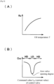
- Fig. 8(A) is a graph showing the relationship between the estimation gain K B and the oil temperature T of the position estimation unit 42 shown in Fig. 5 .
- Fig. 8(B) is a graph showing the relationship between the estimation gain K B of the position estimation unit 42 and the operation command value I ref (current value) of the control valve.
- the estimation gain K B of the arithmetic circuit 53 of the position estimation unit 42 is set in advance so that the gain K B decreases as the oil temperature T decreases.
- the relationship between the estimation gain K B and the oil temperature T is inversely correlated with the relationship between the viscosity of the oil used in the hydraulic actuator 20 and the oil temperature T.
- the position estimation unit 42 can perform accurate position estimation in consideration of the oil temperature, and the response delay due to the decrease in fluidity of the oil at a low temperature is further compensated.
- the estimation gain K B of the position estimation unit 42 is multiplied by the correction coefficient C KB that changes in accordance with the operation command value I ref (current value) of the control valve 25.
- the correction coefficient C KB is set so that the absolute value of the change rate of the estimation gain K B per unit temperature change decreases when the opening degree of the control valve 25 is in the low opening-degree region (first opening-degree region) smaller than the high-opening degree region as compared to that when the opening degree of the control valve 25 is in the high opening-degree region (first opening-degree region).
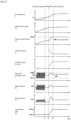
- Fig. 9 is a timing chart showing an example of the oil temperature T at the time of startup by the transmission controller 40 shown in Fig. 4 and other temporal changes.
- the reference temperature T1 is, for example, a value within a range of -20 to -10°C.
- the low-temperature control unit 38 outputs the operation command value I so as to reciprocate the spool 28.
- the waveform of the operation command value I is set, for example, such that the maximum value I high is a value larger than the neutral value In and the minimum value I low is a value smaller than the neutral value I n .
- the increase in the oil temperature T is promoted by forcibly causing the oil to flow by reciprocating the spool 28.
- the difference from the neutral value I n of the maximum value I high is smaller than the difference from the neutral value I n of the minimum value I low .
- the spool 28 cannot respond sensitively to the operation command value I. Therefore, the piston 21b reciprocates on the speed reduction side with respect to the neutral position PS n , and an excessive increase in the output rotation speed N2 is prevented.
- the position control unit 43 obtains the operation command value I ref by closed-loop control. That is, when the position control unit 43 outputs the operation command value I ref corresponding to the deviation ⁇ X, the roller position X is brought closer to the command value X ref , and the transmission ratio SR is brought closer to the command value SR ref .
- the control immediately after the start of the normal control may become unstable.
- the calculation gain G 2 of the position control unit 43 and the estimation gain K B of the position estimation unit 42 are adjusted in accordance with the oil temperature T and the valve opening degree (operation command value I ref ). Therefore, the control when the output rotation speed N2 approaches the command value N2 ref in the initial stage of the closed-loop control is stabilized.
- the command value N2 ref t3
- the calculation gain G 2 and the estimation gain K B of the position estimation unit 42 are adjusted in accordance with the oil temperature T and the valve opening degree (operation command value I ref ), so that the response delay due to the decrease in fluidity of oil at a low temperature is compensated by the gain adjustment. Therefore, it is possible to prevent the instability of the closed-loop control after switching from the warm-up operation to the normal operation while shortening the warm-up operation at the time of low-temperature startup.
- the time lag from the start of closed-loop control to the start of a power generation operation can also be stably reduced.
- the gain of the position control unit 43 may be indirectly adjusted by adding a gain to the signal between the position subtraction unit 49 and the position control unit 43.
- the sensitivity of the internal model of the position estimation unit 42 may be indirectly adjusted by adding a gain to the signal between the position estimation unit 42 and the position subtraction unit 49.
- the adjustment of the calculation gain G 2 by the gain setting unit 60and the adjustment of the estimation gain K B by the gain setting unit 61 may be selectively combined, and, for example, only one or all of them may be implemented.
- the oil temperature acquisition unit instead of the oil temperature sensor 35, a device that acquires information related to an oil temperature (for example, a temperature proportional to the oil temperature) (for example, a sensor that detects a piping temperature) may be used.
- a sensor that detects the roller positions instead of the position estimation unit 42, a sensor that detects the roller positions may be used. That is, as long as the position acquisition unit acquires the actual values of the roller positions, the position acquisition unit may estimate the actual values of the rollers, or may receive a sensor value detected by a roller position sensor.
- the control target of the hydraulic actuator 20 may be a continuously variable transmission of another form instead of the toroidal continuously variable transmission, or may be a device that requires position control other than the transmission. The continuously variable transmission may drive another one without driving the generator.
Landscapes
- Engineering & Computer Science (AREA)
- General Engineering & Computer Science (AREA)
- Mechanical Engineering (AREA)
- Physics & Mathematics (AREA)
- General Physics & Mathematics (AREA)
- Automation & Control Theory (AREA)
- Control Of Transmission Device (AREA)
- Control Of Position Or Direction (AREA)
Claims (4)
- Positionssteuerungsvorrichtung (40), die eine Positionssteuerung durch Ausgeben eines Antriebssignals an ein Steuerventil (25) eines Hydraulikantriebs (20) durchführt, die eine Betriebsposition eines Objekts (16) ändert, wobei die Positionssteuerungsvorrichtung (40) Folgendes umfasst:eine Öltemperaturerfassungseinheit (35), die Informationen über eine Öltemperatur des Hydraulikantriebs (20) erfasst;eine Positionserfassungseinheit (42), die einen Istwert einer Betriebsposition des Objekts (16) erfasst;eine Positionssteuerungseinheit (43), die einen Betriebsbefehlswert für das Steuerventil (25) durch eine Steuerung (LP2) mit geschlossenem Regelkreis berechnet, um eine Abweichung zwischen einem Sollwert der Betriebsposition des Objekts (16) und dem Istwert zu verringern; undeine Verstärkungseinstellungseinheit (60, 61), die mindestens eine Verstärkung (G2, KB) der Steuerung (LP2) mit geschlossenem Regelkreis ändert, sodass sich eine Empfindlichkeit der Steuerung (LP2) mit geschlossenem Regelkreis mit abnehmender Öltemperatur erhöht,wobei die mindestens eine Verstärkung (G2, KB) eine erste Verstärkung (G2) ist, die verwendet wird, um den Betriebsbefehlswert anhand der Abweichung zu erlangen,wobei die Verstärkungseinstellungseinheit (60) die erste Verstärkung (G2) mit abnehmender Öltemperatur erhöht undwobei die erste Verstärkung (G2) eine Berechnungsverstärkung der Positionssteuerungseinheit (43) ist,wobei die Positionssteuerungsvorrichtung (40) ferner eine Positionssubtraktionseinheit (49) umfasst, welche die Abweichung erlangt,dadurch gekennzeichnet, dass eine zweite Verstärkung (KB) verwendet wird, um den in die Positionssubtraktionseinheit (49) eingegebenen Istwert zu erlangen, undwobei die Verstärkungseinstellungseinheit (61) die zweite Verstärkung (KB) mit abnehmender Öltemperatur verringert.
- Positionssteuerungsvorrichtung (40) nach Anspruch 1,wobei die Positionserfassungseinheit (42) eine Positionsschätzeinheit (42) ist, die den Istwert der Betriebsposition des Objekts (16) schätzt, undwobei die zweite Verstärkung (KB) eine Empfindlichkeit eines internen Modells der Positionsschätzeinheit (42) beinhaltet.
- Positionssteuerungsvorrichtung (40) nach Anspruch 1 oder 2, wobei das Objekt (16) ein Getriebeelement (16) ist, das ein Übersetzungsverhältnis eines stufenlosen Getriebes (10) gemäß einer Positionsänderung davon ändert.
- Positionssteuerungsvorrichtung (40) nach einem der Ansprüche 1 bis 3, wobei die Verstärkungseinstellungseinheit (60) eine Korrektur durchführt, sodass sich ein Absolutwert einer Änderungsrate der Verstärkung (G2) in Bezug auf eine Änderung der Öltemperatur erhöht, wenn sich ein Öffnungsgrad des Steuerventils (25) in einem zweiten Öffnungsgradbereich (LD) befindet, der kleiner als ein erster Öffnungsgradbereich (HD) ist, im Vergleich dazu, wenn sich der Öffnungsgrad des Steuerventils (25) in dem ersten Öffnungsgradbereich (HD) befindet.
Priority Applications (1)
| Application Number | Priority Date | Filing Date | Title |
|---|---|---|---|
| EP22199058.3A EP4134775B1 (de) | 2017-05-31 | 2018-05-16 | Positionsregler eines stufenlosen getriebes |
Applications Claiming Priority (2)
| Application Number | Priority Date | Filing Date | Title |
|---|---|---|---|
| JP2017108177A JP6952498B2 (ja) | 2017-05-31 | 2017-05-31 | 位置制御装置 |
| PCT/JP2018/018953 WO2018221226A1 (ja) | 2017-05-31 | 2018-05-16 | 位置制御装置 |
Related Child Applications (2)
| Application Number | Title | Priority Date | Filing Date |
|---|---|---|---|
| EP22199058.3A Division EP4134775B1 (de) | 2017-05-31 | 2018-05-16 | Positionsregler eines stufenlosen getriebes |
| EP22199058.3A Division-Into EP4134775B1 (de) | 2017-05-31 | 2018-05-16 | Positionsregler eines stufenlosen getriebes |
Publications (3)
| Publication Number | Publication Date |
|---|---|
| EP3633484A1 EP3633484A1 (de) | 2020-04-08 |
| EP3633484A4 EP3633484A4 (de) | 2021-03-10 |
| EP3633484B1 true EP3633484B1 (de) | 2023-06-07 |
Family
ID=64455912
Family Applications (2)
| Application Number | Title | Priority Date | Filing Date |
|---|---|---|---|
| EP22199058.3A Active EP4134775B1 (de) | 2017-05-31 | 2018-05-16 | Positionsregler eines stufenlosen getriebes |
| EP18808789.4A Active EP3633484B1 (de) | 2017-05-31 | 2018-05-16 | Positionsregler |
Family Applications Before (1)
| Application Number | Title | Priority Date | Filing Date |
|---|---|---|---|
| EP22199058.3A Active EP4134775B1 (de) | 2017-05-31 | 2018-05-16 | Positionsregler eines stufenlosen getriebes |
Country Status (4)
| Country | Link |
|---|---|
| US (1) | US11131380B2 (de) |
| EP (2) | EP4134775B1 (de) |
| JP (1) | JP6952498B2 (de) |
| WO (1) | WO2018221226A1 (de) |
Families Citing this family (4)
| Publication number | Priority date | Publication date | Assignee | Title |
|---|---|---|---|---|
| JP6907073B2 (ja) * | 2017-08-31 | 2021-07-21 | 川崎重工業株式会社 | トロイダル無段変速機の変速制御装置 |
| CN115283745B (zh) * | 2022-06-15 | 2025-04-08 | 中冶南方工程技术有限公司 | 一种飞剪的剪刃速度控制方法及系统 |
| CN118502300B (zh) * | 2024-05-13 | 2025-01-03 | 北京和利时电机技术有限公司 | 一种简化的电子背压闭环控制方法 |
| CN120447376A (zh) * | 2025-04-30 | 2025-08-08 | 清华大学 | 飞行环境模拟系统的气流鲁棒性控制方法和装置 |
Family Cites Families (13)
| Publication number | Priority date | Publication date | Assignee | Title |
|---|---|---|---|---|
| JPS6415508A (en) * | 1987-07-07 | 1989-01-19 | Mitsubishi Electric Corp | Electronic controller for flow control valve |
| JP3374677B2 (ja) * | 1996-10-31 | 2003-02-10 | 日産自動車株式会社 | 無段変速機の変速制御装置 |
| JP3460547B2 (ja) * | 1997-11-13 | 2003-10-27 | 日産自動車株式会社 | 無段変速機の変速制御装置 |
| JP3301388B2 (ja) * | 1998-07-23 | 2002-07-15 | 日産自動車株式会社 | 無段変速機の変速制御装置 |
| US6142908A (en) | 1998-07-01 | 2000-11-07 | Nissan Motor Co., Ltd. | Speed ratio controller and control method of continuously variable transmission |
| US6312358B1 (en) * | 1999-05-21 | 2001-11-06 | Advanced Technology Institute Of Commuter-Helicopter, Ltd. | Constant speed drive apparatus for aircraft generator and traction speed change apparatus |
| JP2001164953A (ja) * | 1999-12-14 | 2001-06-19 | Honda Motor Co Ltd | 内燃機関の動弁装置 |
| JP3680739B2 (ja) * | 2001-02-06 | 2005-08-10 | 日産自動車株式会社 | 無段変速機の変速制御装置 |
| JP4198937B2 (ja) * | 2002-05-17 | 2008-12-17 | 株式会社豊田中央研究所 | トロイダル式cvtの変速制御装置 |
| JP4495117B2 (ja) * | 2006-06-30 | 2010-06-30 | 川崎重工業株式会社 | 無段変速機の制御方法および制御システム |
| JP2010036694A (ja) * | 2008-08-04 | 2010-02-18 | Toyota Motor Corp | 車両用駆動装置の制御装置 |
| JP6731042B2 (ja) * | 2016-03-08 | 2020-07-29 | 川崎重工業株式会社 | 変速制御装置 |
| JP6565841B2 (ja) * | 2016-09-09 | 2019-08-28 | 株式会社デンソー | シフトレンジ制御装置 |
-
2017
- 2017-05-31 JP JP2017108177A patent/JP6952498B2/ja active Active
-
2018
- 2018-05-16 EP EP22199058.3A patent/EP4134775B1/de active Active
- 2018-05-16 EP EP18808789.4A patent/EP3633484B1/de active Active
- 2018-05-16 WO PCT/JP2018/018953 patent/WO2018221226A1/ja not_active Ceased
- 2018-05-16 US US16/617,594 patent/US11131380B2/en active Active
Also Published As
| Publication number | Publication date |
|---|---|
| EP4134775B1 (de) | 2024-01-03 |
| EP3633484A1 (de) | 2020-04-08 |
| US20200182351A1 (en) | 2020-06-11 |
| US11131380B2 (en) | 2021-09-28 |
| WO2018221226A1 (ja) | 2018-12-06 |
| JP2018205902A (ja) | 2018-12-27 |
| EP4134775A1 (de) | 2023-02-15 |
| JP6952498B2 (ja) | 2021-10-20 |
| EP3633484A4 (de) | 2021-03-10 |
Similar Documents
| Publication | Publication Date | Title |
|---|---|---|
| EP3633484B1 (de) | Positionsregler | |
| EP4209686A1 (de) | Hydraulische druckausgleichspumpe, drehzahlsteuerungssystem und steuerungsverfahren sowie baumaschine | |
| CN111828622B (zh) | 静液式轴向活塞泵、静液式行驶驱动器以及控制方法 | |
| US20140060034A1 (en) | Electro-Hydraulic Control Design for Pump Discharge Pressure Control | |
| EP3633485B1 (de) | Positionssteuerungsvorrichtung | |
| US10508735B2 (en) | Controller of toroidal continuously variable transmission | |
| EP3677814B1 (de) | Getriebesteuerungsvorrichtung für stufenloses ringgetriebe | |
| US20190348937A1 (en) | Power generation system and method of controlling same | |
| JP3192054B2 (ja) | 油圧ポンプの傾転角制御装置 | |
| US20190032776A1 (en) | Transmission controller | |
| JPH07332247A (ja) | 可変容量油圧ポンプの制御装置 | |
| JP4720766B2 (ja) | バルブタイミング可変装置及び油圧アクチュエータ制御装置 | |
| JP3029778B2 (ja) | 建設機械の制御装置 | |
| JPH1150871A (ja) | 建設機械のエンジン制御装置 | |
| JP2002195164A (ja) | 吐出流量制御装置 | |
| CN115324758A (zh) | 一种挖掘机功率控制方法 | |
| JP2016151174A (ja) | 液圧駆動システム | |
| JP2009085062A (ja) | エンジンの電子ガバナ |
Legal Events
| Date | Code | Title | Description |
|---|---|---|---|
| STAA | Information on the status of an ep patent application or granted ep patent |
Free format text: STATUS: THE INTERNATIONAL PUBLICATION HAS BEEN MADE |
|
| PUAI | Public reference made under article 153(3) epc to a published international application that has entered the european phase |
Free format text: ORIGINAL CODE: 0009012 |
|
| STAA | Information on the status of an ep patent application or granted ep patent |
Free format text: STATUS: REQUEST FOR EXAMINATION WAS MADE |
|
| 17P | Request for examination filed |
Effective date: 20191213 |
|
| AK | Designated contracting states |
Kind code of ref document: A1 Designated state(s): AL AT BE BG CH CY CZ DE DK EE ES FI FR GB GR HR HU IE IS IT LI LT LU LV MC MK MT NL NO PL PT RO RS SE SI SK SM TR |
|
| AX | Request for extension of the european patent |
Extension state: BA ME |
|
| DAV | Request for validation of the european patent (deleted) | ||
| DAX | Request for extension of the european patent (deleted) | ||
| A4 | Supplementary search report drawn up and despatched |
Effective date: 20210210 |
|
| RIC1 | Information provided on ipc code assigned before grant |
Ipc: F16H 61/02 20060101ALI20210204BHEP Ipc: G05D 3/12 20060101AFI20210204BHEP Ipc: F16H 61/664 20060101ALI20210204BHEP |
|
| STAA | Information on the status of an ep patent application or granted ep patent |
Free format text: STATUS: EXAMINATION IS IN PROGRESS |
|
| 17Q | First examination report despatched |
Effective date: 20220323 |
|
| GRAP | Despatch of communication of intention to grant a patent |
Free format text: ORIGINAL CODE: EPIDOSNIGR1 |
|
| STAA | Information on the status of an ep patent application or granted ep patent |
Free format text: STATUS: GRANT OF PATENT IS INTENDED |
|
| INTG | Intention to grant announced |
Effective date: 20230123 |
|
| GRAS | Grant fee paid |
Free format text: ORIGINAL CODE: EPIDOSNIGR3 |
|
| GRAA | (expected) grant |
Free format text: ORIGINAL CODE: 0009210 |
|
| STAA | Information on the status of an ep patent application or granted ep patent |
Free format text: STATUS: THE PATENT HAS BEEN GRANTED |
|
| AK | Designated contracting states |
Kind code of ref document: B1 Designated state(s): AL AT BE BG CH CY CZ DE DK EE ES FI FR GB GR HR HU IE IS IT LI LT LU LV MC MK MT NL NO PL PT RO RS SE SI SK SM TR |
|
| REG | Reference to a national code |
Ref country code: GB Ref legal event code: FG4D |
|
| REG | Reference to a national code |
Ref country code: CH Ref legal event code: EP Ref country code: AT Ref legal event code: REF Ref document number: 1576990 Country of ref document: AT Kind code of ref document: T Effective date: 20230615 Ref country code: DE Ref legal event code: R096 Ref document number: 602018051347 Country of ref document: DE |
|
| REG | Reference to a national code |
Ref country code: LT Ref legal event code: MG9D |
|
| REG | Reference to a national code |
Ref country code: NL Ref legal event code: MP Effective date: 20230607 |
|
| PG25 | Lapsed in a contracting state [announced via postgrant information from national office to epo] |
Ref country code: SE Free format text: LAPSE BECAUSE OF FAILURE TO SUBMIT A TRANSLATION OF THE DESCRIPTION OR TO PAY THE FEE WITHIN THE PRESCRIBED TIME-LIMIT Effective date: 20230607 Ref country code: NO Free format text: LAPSE BECAUSE OF FAILURE TO SUBMIT A TRANSLATION OF THE DESCRIPTION OR TO PAY THE FEE WITHIN THE PRESCRIBED TIME-LIMIT Effective date: 20230907 Ref country code: ES Free format text: LAPSE BECAUSE OF FAILURE TO SUBMIT A TRANSLATION OF THE DESCRIPTION OR TO PAY THE FEE WITHIN THE PRESCRIBED TIME-LIMIT Effective date: 20230607 |
|
| REG | Reference to a national code |
Ref country code: AT Ref legal event code: MK05 Ref document number: 1576990 Country of ref document: AT Kind code of ref document: T Effective date: 20230607 |
|
| PG25 | Lapsed in a contracting state [announced via postgrant information from national office to epo] |
Ref country code: RS Free format text: LAPSE BECAUSE OF FAILURE TO SUBMIT A TRANSLATION OF THE DESCRIPTION OR TO PAY THE FEE WITHIN THE PRESCRIBED TIME-LIMIT Effective date: 20230607 Ref country code: NL Free format text: LAPSE BECAUSE OF FAILURE TO SUBMIT A TRANSLATION OF THE DESCRIPTION OR TO PAY THE FEE WITHIN THE PRESCRIBED TIME-LIMIT Effective date: 20230607 Ref country code: LV Free format text: LAPSE BECAUSE OF FAILURE TO SUBMIT A TRANSLATION OF THE DESCRIPTION OR TO PAY THE FEE WITHIN THE PRESCRIBED TIME-LIMIT Effective date: 20230607 Ref country code: LT Free format text: LAPSE BECAUSE OF FAILURE TO SUBMIT A TRANSLATION OF THE DESCRIPTION OR TO PAY THE FEE WITHIN THE PRESCRIBED TIME-LIMIT Effective date: 20230607 Ref country code: HR Free format text: LAPSE BECAUSE OF FAILURE TO SUBMIT A TRANSLATION OF THE DESCRIPTION OR TO PAY THE FEE WITHIN THE PRESCRIBED TIME-LIMIT Effective date: 20230607 Ref country code: GR Free format text: LAPSE BECAUSE OF FAILURE TO SUBMIT A TRANSLATION OF THE DESCRIPTION OR TO PAY THE FEE WITHIN THE PRESCRIBED TIME-LIMIT Effective date: 20230908 |
|
| PG25 | Lapsed in a contracting state [announced via postgrant information from national office to epo] |
Ref country code: FI Free format text: LAPSE BECAUSE OF FAILURE TO SUBMIT A TRANSLATION OF THE DESCRIPTION OR TO PAY THE FEE WITHIN THE PRESCRIBED TIME-LIMIT Effective date: 20230607 |
|
| PG25 | Lapsed in a contracting state [announced via postgrant information from national office to epo] |
Ref country code: SK Free format text: LAPSE BECAUSE OF FAILURE TO SUBMIT A TRANSLATION OF THE DESCRIPTION OR TO PAY THE FEE WITHIN THE PRESCRIBED TIME-LIMIT Effective date: 20230607 |
|
| PG25 | Lapsed in a contracting state [announced via postgrant information from national office to epo] |
Ref country code: IS Free format text: LAPSE BECAUSE OF FAILURE TO SUBMIT A TRANSLATION OF THE DESCRIPTION OR TO PAY THE FEE WITHIN THE PRESCRIBED TIME-LIMIT Effective date: 20231007 |
|
| PG25 | Lapsed in a contracting state [announced via postgrant information from national office to epo] |
Ref country code: SM Free format text: LAPSE BECAUSE OF FAILURE TO SUBMIT A TRANSLATION OF THE DESCRIPTION OR TO PAY THE FEE WITHIN THE PRESCRIBED TIME-LIMIT Effective date: 20230607 Ref country code: SK Free format text: LAPSE BECAUSE OF FAILURE TO SUBMIT A TRANSLATION OF THE DESCRIPTION OR TO PAY THE FEE WITHIN THE PRESCRIBED TIME-LIMIT Effective date: 20230607 Ref country code: RO Free format text: LAPSE BECAUSE OF FAILURE TO SUBMIT A TRANSLATION OF THE DESCRIPTION OR TO PAY THE FEE WITHIN THE PRESCRIBED TIME-LIMIT Effective date: 20230607 Ref country code: PT Free format text: LAPSE BECAUSE OF FAILURE TO SUBMIT A TRANSLATION OF THE DESCRIPTION OR TO PAY THE FEE WITHIN THE PRESCRIBED TIME-LIMIT Effective date: 20231009 Ref country code: IS Free format text: LAPSE BECAUSE OF FAILURE TO SUBMIT A TRANSLATION OF THE DESCRIPTION OR TO PAY THE FEE WITHIN THE PRESCRIBED TIME-LIMIT Effective date: 20231007 Ref country code: EE Free format text: LAPSE BECAUSE OF FAILURE TO SUBMIT A TRANSLATION OF THE DESCRIPTION OR TO PAY THE FEE WITHIN THE PRESCRIBED TIME-LIMIT Effective date: 20230607 Ref country code: CZ Free format text: LAPSE BECAUSE OF FAILURE TO SUBMIT A TRANSLATION OF THE DESCRIPTION OR TO PAY THE FEE WITHIN THE PRESCRIBED TIME-LIMIT Effective date: 20230607 Ref country code: AT Free format text: LAPSE BECAUSE OF FAILURE TO SUBMIT A TRANSLATION OF THE DESCRIPTION OR TO PAY THE FEE WITHIN THE PRESCRIBED TIME-LIMIT Effective date: 20230607 |
|
| PG25 | Lapsed in a contracting state [announced via postgrant information from national office to epo] |
Ref country code: PL Free format text: LAPSE BECAUSE OF FAILURE TO SUBMIT A TRANSLATION OF THE DESCRIPTION OR TO PAY THE FEE WITHIN THE PRESCRIBED TIME-LIMIT Effective date: 20230607 |
|
| REG | Reference to a national code |
Ref country code: DE Ref legal event code: R097 Ref document number: 602018051347 Country of ref document: DE |
|
| PLBE | No opposition filed within time limit |
Free format text: ORIGINAL CODE: 0009261 |
|
| STAA | Information on the status of an ep patent application or granted ep patent |
Free format text: STATUS: NO OPPOSITION FILED WITHIN TIME LIMIT |
|
| PG25 | Lapsed in a contracting state [announced via postgrant information from national office to epo] |
Ref country code: DK Free format text: LAPSE BECAUSE OF FAILURE TO SUBMIT A TRANSLATION OF THE DESCRIPTION OR TO PAY THE FEE WITHIN THE PRESCRIBED TIME-LIMIT Effective date: 20230607 |
|
| PG25 | Lapsed in a contracting state [announced via postgrant information from national office to epo] |
Ref country code: SI Free format text: LAPSE BECAUSE OF FAILURE TO SUBMIT A TRANSLATION OF THE DESCRIPTION OR TO PAY THE FEE WITHIN THE PRESCRIBED TIME-LIMIT Effective date: 20230607 |
|
| 26N | No opposition filed |
Effective date: 20240308 |
|
| PG25 | Lapsed in a contracting state [announced via postgrant information from national office to epo] |
Ref country code: SI Free format text: LAPSE BECAUSE OF FAILURE TO SUBMIT A TRANSLATION OF THE DESCRIPTION OR TO PAY THE FEE WITHIN THE PRESCRIBED TIME-LIMIT Effective date: 20230607 Ref country code: IT Free format text: LAPSE BECAUSE OF FAILURE TO SUBMIT A TRANSLATION OF THE DESCRIPTION OR TO PAY THE FEE WITHIN THE PRESCRIBED TIME-LIMIT Effective date: 20230607 |
|
| PG25 | Lapsed in a contracting state [announced via postgrant information from national office to epo] |
Ref country code: BG Free format text: LAPSE BECAUSE OF FAILURE TO SUBMIT A TRANSLATION OF THE DESCRIPTION OR TO PAY THE FEE WITHIN THE PRESCRIBED TIME-LIMIT Effective date: 20230607 |
|
| PG25 | Lapsed in a contracting state [announced via postgrant information from national office to epo] |
Ref country code: BG Free format text: LAPSE BECAUSE OF FAILURE TO SUBMIT A TRANSLATION OF THE DESCRIPTION OR TO PAY THE FEE WITHIN THE PRESCRIBED TIME-LIMIT Effective date: 20230607 |
|
| REG | Reference to a national code |
Ref country code: CH Ref legal event code: PL |
|
| PG25 | Lapsed in a contracting state [announced via postgrant information from national office to epo] |
Ref country code: MC Free format text: LAPSE BECAUSE OF FAILURE TO SUBMIT A TRANSLATION OF THE DESCRIPTION OR TO PAY THE FEE WITHIN THE PRESCRIBED TIME-LIMIT Effective date: 20230607 |
|
| PG25 | Lapsed in a contracting state [announced via postgrant information from national office to epo] |
Ref country code: LU Free format text: LAPSE BECAUSE OF NON-PAYMENT OF DUE FEES Effective date: 20240516 |
|
| PG25 | Lapsed in a contracting state [announced via postgrant information from national office to epo] |
Ref country code: MC Free format text: LAPSE BECAUSE OF FAILURE TO SUBMIT A TRANSLATION OF THE DESCRIPTION OR TO PAY THE FEE WITHIN THE PRESCRIBED TIME-LIMIT Effective date: 20230607 Ref country code: LU Free format text: LAPSE BECAUSE OF NON-PAYMENT OF DUE FEES Effective date: 20240516 Ref country code: CH Free format text: LAPSE BECAUSE OF NON-PAYMENT OF DUE FEES Effective date: 20240531 |
|
| REG | Reference to a national code |
Ref country code: BE Ref legal event code: MM Effective date: 20240531 |
|
| PG25 | Lapsed in a contracting state [announced via postgrant information from national office to epo] |
Ref country code: IE Free format text: LAPSE BECAUSE OF NON-PAYMENT OF DUE FEES Effective date: 20240516 |
|
| PG25 | Lapsed in a contracting state [announced via postgrant information from national office to epo] |
Ref country code: BE Free format text: LAPSE BECAUSE OF NON-PAYMENT OF DUE FEES Effective date: 20240531 |
|
| PGFP | Annual fee paid to national office [announced via postgrant information from national office to epo] |
Ref country code: DE Payment date: 20250402 Year of fee payment: 8 |
|
| PGFP | Annual fee paid to national office [announced via postgrant information from national office to epo] |
Ref country code: FR Payment date: 20250401 Year of fee payment: 8 |
|
| PG25 | Lapsed in a contracting state [announced via postgrant information from national office to epo] |
Ref country code: CY Free format text: LAPSE BECAUSE OF FAILURE TO SUBMIT A TRANSLATION OF THE DESCRIPTION OR TO PAY THE FEE WITHIN THE PRESCRIBED TIME-LIMIT; INVALID AB INITIO Effective date: 20180516 |
|
| PG25 | Lapsed in a contracting state [announced via postgrant information from national office to epo] |
Ref country code: HU Free format text: LAPSE BECAUSE OF FAILURE TO SUBMIT A TRANSLATION OF THE DESCRIPTION OR TO PAY THE FEE WITHIN THE PRESCRIBED TIME-LIMIT; INVALID AB INITIO Effective date: 20180516 |
|
| PGFP | Annual fee paid to national office [announced via postgrant information from national office to epo] |
Ref country code: GB Payment date: 20260323 Year of fee payment: 9 |