EP3633122B1 - Gerät für die unterstützung des auf- und abbaus von weidezäunen - Google Patents
Gerät für die unterstützung des auf- und abbaus von weidezäunen Download PDFInfo
- Publication number
- EP3633122B1 EP3633122B1 EP19000448.1A EP19000448A EP3633122B1 EP 3633122 B1 EP3633122 B1 EP 3633122B1 EP 19000448 A EP19000448 A EP 19000448A EP 3633122 B1 EP3633122 B1 EP 3633122B1
- Authority
- EP
- European Patent Office
- Prior art keywords
- reel
- drive
- shaft
- slip clutch
- fence
- Prior art date
- Legal status (The legal status is an assumption and is not a legal conclusion. Google has not performed a legal analysis and makes no representation as to the accuracy of the status listed.)
- Active
Links
- 238000010276 construction Methods 0.000 title description 7
- 239000000463 material Substances 0.000 claims description 30
- 238000004804 winding Methods 0.000 description 6
- 235000004443 Ricinus communis Nutrition 0.000 description 2
- 240000000528 Ricinus communis Species 0.000 description 2
- 229910000831 Steel Inorganic materials 0.000 description 2
- 238000005096 rolling process Methods 0.000 description 2
- 239000010959 steel Substances 0.000 description 2
- 241001465754 Metazoa Species 0.000 description 1
- 238000012423 maintenance Methods 0.000 description 1
- 230000007257 malfunction Effects 0.000 description 1
- 238000004806 packaging method and process Methods 0.000 description 1
- 238000009304 pastoral farming Methods 0.000 description 1
Images

Classifications
-
- E—FIXED CONSTRUCTIONS
- E04—BUILDING
- E04H—BUILDINGS OR LIKE STRUCTURES FOR PARTICULAR PURPOSES; SWIMMING OR SPLASH BATHS OR POOLS; MASTS; FENCING; TENTS OR CANOPIES, IN GENERAL
- E04H17/00—Fencing, e.g. fences, enclosures, corrals
- E04H17/26—Devices for erecting or removing fences
- E04H17/261—Devices for erecting or removing fences for post and wire handling
- E04H17/266—Devices for erecting or removing fences for post and wire handling for stretching or winding wire or wire mesh
-
- A—HUMAN NECESSITIES
- A01—AGRICULTURE; FORESTRY; ANIMAL HUSBANDRY; HUNTING; TRAPPING; FISHING
- A01K—ANIMAL HUSBANDRY; AVICULTURE; APICULTURE; PISCICULTURE; FISHING; REARING OR BREEDING ANIMALS, NOT OTHERWISE PROVIDED FOR; NEW BREEDS OF ANIMALS
- A01K3/00—Pasturing equipment, e.g. tethering devices; Grids for preventing cattle from straying; Electrified wire fencing
- A01K3/001—Portable, temporary, and collapsible fencing for pastures
-
- A—HUMAN NECESSITIES
- A01—AGRICULTURE; FORESTRY; ANIMAL HUSBANDRY; HUNTING; TRAPPING; FISHING
- A01K—ANIMAL HUSBANDRY; AVICULTURE; APICULTURE; PISCICULTURE; FISHING; REARING OR BREEDING ANIMALS, NOT OTHERWISE PROVIDED FOR; NEW BREEDS OF ANIMALS
- A01K3/00—Pasturing equipment, e.g. tethering devices; Grids for preventing cattle from straying; Electrified wire fencing
- A01K3/005—Electrified fencing for pastures
-
- B—PERFORMING OPERATIONS; TRANSPORTING
- B65—CONVEYING; PACKING; STORING; HANDLING THIN OR FILAMENTARY MATERIAL
- B65H—HANDLING THIN OR FILAMENTARY MATERIAL, e.g. SHEETS, WEBS, CABLES
- B65H75/00—Storing webs, tapes, or filamentary material, e.g. on reels
- B65H75/02—Cores, formers, supports, or holders for coiled, wound, or folded material, e.g. reels, spindles, bobbins, cop tubes, cans, mandrels or chucks
- B65H75/34—Cores, formers, supports, or holders for coiled, wound, or folded material, e.g. reels, spindles, bobbins, cop tubes, cans, mandrels or chucks specially adapted or mounted for storing and repeatedly paying-out and re-storing lengths of material provided for particular purposes, e.g. anchored hoses, power cables
- B65H75/38—Cores, formers, supports, or holders for coiled, wound, or folded material, e.g. reels, spindles, bobbins, cop tubes, cans, mandrels or chucks specially adapted or mounted for storing and repeatedly paying-out and re-storing lengths of material provided for particular purposes, e.g. anchored hoses, power cables involving the use of a core or former internal to, and supporting, a stored package of material
- B65H75/40—Cores, formers, supports, or holders for coiled, wound, or folded material, e.g. reels, spindles, bobbins, cop tubes, cans, mandrels or chucks specially adapted or mounted for storing and repeatedly paying-out and re-storing lengths of material provided for particular purposes, e.g. anchored hoses, power cables involving the use of a core or former internal to, and supporting, a stored package of material mobile or transportable
- B65H75/42—Cores, formers, supports, or holders for coiled, wound, or folded material, e.g. reels, spindles, bobbins, cop tubes, cans, mandrels or chucks specially adapted or mounted for storing and repeatedly paying-out and re-storing lengths of material provided for particular purposes, e.g. anchored hoses, power cables involving the use of a core or former internal to, and supporting, a stored package of material mobile or transportable attached to, or forming part of, mobile tools, machines or vehicles
- B65H75/425—Cores, formers, supports, or holders for coiled, wound, or folded material, e.g. reels, spindles, bobbins, cop tubes, cans, mandrels or chucks specially adapted or mounted for storing and repeatedly paying-out and re-storing lengths of material provided for particular purposes, e.g. anchored hoses, power cables involving the use of a core or former internal to, and supporting, a stored package of material mobile or transportable attached to, or forming part of, mobile tools, machines or vehicles attached to, or forming part of a vehicle, e.g. truck, trailer, vessel
-
- E—FIXED CONSTRUCTIONS
- E04—BUILDING
- E04H—BUILDINGS OR LIKE STRUCTURES FOR PARTICULAR PURPOSES; SWIMMING OR SPLASH BATHS OR POOLS; MASTS; FENCING; TENTS OR CANOPIES, IN GENERAL
- E04H17/00—Fencing, e.g. fences, enclosures, corrals
- E04H17/26—Devices for erecting or removing fences
-
- E—FIXED CONSTRUCTIONS
- E04—BUILDING
- E04H—BUILDINGS OR LIKE STRUCTURES FOR PARTICULAR PURPOSES; SWIMMING OR SPLASH BATHS OR POOLS; MASTS; FENCING; TENTS OR CANOPIES, IN GENERAL
- E04H17/00—Fencing, e.g. fences, enclosures, corrals
- E04H17/26—Devices for erecting or removing fences
- E04H17/261—Devices for erecting or removing fences for post and wire handling
Definitions
- the invention relates to a device according to claim 1 for supporting the construction and dismantling of pasture fences.
- the basic functions known per se and optional advantageous additional functions known per se of a device for supporting the construction and dismantling of pasture fences are shown in the WO 98/48135 A1 example device shown:
- the device according to the WO 98/48135 A1 is mounted on a vehicle. It comprises one or more reels each for a flexible longitudinal material (fence tape or fence wire), one or more guide eyes for guiding the longitudinal material between the reels and the fence, a rod made up of adjustable longitudinal parts, which carries the guide eye or eyes, and a Storage facility for fence posts to be carried.
- the rest of the drive train which acts on a reel, comprises a drive motor and a slip clutch.
- the reel can only be rotated by overcoming the torque limited by the slip clutch.
- the drive is running, the reel is driven to wind up longitudinal material on its outer surface, the torque which causes the tensile force on the longitudinal material being limited by the slip clutch.
- the absolutely necessary parts or functions of the device are a reel for winding and unwinding the longitudinal material, whereby a braking option and a motor drive option for the reel must be given, as well as a fastening device to be able to attach the device to a vehicle.
- the DE 3443972 A1 Figure 3 shows a device according to the closest prior art of claim 1, which is part of a mobile agricultural machine, and supports the winding and unwinding of flexible longitudinal material for pasture fences.
- the device comprises a reel on which the flexible longitudinal material is to be wound, as well as a drive motor which can drive the reel to rotate via a V-belt, which can also serve as a slip clutch.
- the reel is located between the two holding arms of a rocker arm of the mobile agricultural machine.
- the reel is non-rotatably connected to a shaft arranged coaxially with it.
- the shaft is on each of the two retaining arms Rocker held rotatably mounted, and it protrudes with both of its ends over the width of the rocker and the stub shafts are freely accessible.
- the device has no housing; all moving parts are freely accessible.
- the GB 2082221 A shows a device which can be fixed to the support arms of a mobile agricultural machine and supports the winding and unwinding of flexible longitudinal material for pasture fences and supports the driving of fence posts into the earth.
- the flexible longitudinal material To work with the flexible longitudinal material, it has a rectangular base frame on which several reel shafts and a drive shaft are rotatably mounted, the movement being transmitted between the drive shaft and the reel shafts via belt drives and slip clutches. None of these parts are in a housing.
- the GB 2048200 A shows one for the unwinding and winding up of wires for an electric fence.
- the device can be moved like a sliding chest in that it is partially lifted and pushed or pulled by two handles that are arranged at the end of protruding levers, while rolling with a wheel on the ground.
- Rotary movement of the shaft of the wheel rolling on the ground drives a shaft via a belt on which reels for the wires are arranged one behind the other.
- the rotary movement of the latter shaft is transmitted to the individual reels with the interposition of a slip clutch.
- the GB 2218687 A shows a mobile work machine for unwinding and winding up wires for a pasture fence. It has several reel shafts which can be driven to rotate by means of a belt drive, the drive wheel for the belt being a wheel with which the working machine rolls on the ground. A slip clutch for the reel drive can also be implemented by loosening the drive belt.
- the object on which the invention is based is to improve a device of the type discussed for the support of the construction and dismantling of pasture fences so that, while avoiding the problems mentioned in the previous paragraph, the rotational movement of a reel causing the winding of longitudinal material is optionally can be done by a higher drive torque and at a higher speed than is optimal for normal operation of the device.
- a reel shaft is provided, which is arranged coaxially to the reel and is non-rotatably connected to it against relative rotation about the common axis, and has a stub shaft, the end face and lateral surface of which are arranged freely accessible.
- a stub shaft in this sense is an end-side longitudinal area of a shaft).
- This measure ensures that the reel shaft at the freely accessible end area with the tool engagement part of a machine turning tool that does not belong to the device but is already available in every agricultural operation, such as a Hand drill or a cordless screwdriver, can be connected, and can be driven to rotary motion by the machine rotary tool, with which the reel can also be driven to rotary motion, bypassing its standard drive. Since this also bridges the slip clutch, the reel can be driven with a significantly higher torque and a significantly higher speed than would be possible with the standard drive.
- Outlined device 1 has a base frame 2, wheels 3, holding parts 4, a drive housing 5, reel shafts 6, reels 7 for flexible longitudinal material 8, a linkage 9, guide eyes 10 and a storage device 11 for fence posts 12.
- the device 1 can be moved on its own at least on firm, level ground, such as in a barn.
- the holding parts 4 are used to anchor and lift the device 1 for the intended use on the hydraulically movable holding arms of a mobile agricultural machine, such as typically a tractor, in order to be able to move it through them over meadows and uneven terrain.
- the drive housing 5 carries the reel shafts 6 and houses the essential parts for their rotating drive.
- the reel shafts 6 carry the reels 7 and are non-rotatably connected to them.
- the flexible longitudinal material 8 for the fence ie fence wire or fence tape
- the linkage 9 fastened to the base frame 2 typically consists of hollow steel profiles fastened to one another in adjustable plug connections; its function is to carry the guide eyes 10.
- the longitudinal material 8 is guided through the guide eyelets 10 in the course between the reels 7 and the fence posts 12 anchored in the terrain.
- the guide eyes 10 are strong, rigid bent wire parts, which are spirally shaped in a central longitudinal part to form a type of thread.
- the storage device 11 is designed in this case as a plate with a grid perforation, the fence posts 12 being able to be inserted into the holes of the grid perforation as intended and thus being kept in an orderly manner.
- the storage device 11 can be pivoted about its central axis with respect to the base frame 2 carrying it; This makes it particularly convenient to equip the storage device 11 and remove it.
- the essential special feature of the device 1 according to the invention lies in the rotary drive of the reels 7.
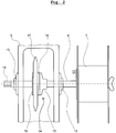
- An exemplary embodiment according to the invention is shown in FIG Fig. 2 illustrated.
- the reel 7 is non-rotatably connected to a coaxially arranged reel shaft 6, which is typically a round bar made of steel.
- the reel shaft 6 is passed through the drive housing 5 and held at the feed-through points through the walls of the drive housing 5 by bearings 13 so as to be rotatable about its axis.
- a slip clutch 14 is arranged on the reel shaft 6, the output-side part 15 of which is rigidly connected to the reel shaft 6 and the drive-side part 16 of which is rigidly connected to a sprocket 17.
- torque is transmitted by a friction lining 18, if necessary.
- the chain wheel 17 and thus the drive-side part 16 is possibly driven via a drive chain (not shown), which in turn is driven by a drive motor, typically an electric motor or a hydraulic motor.
- the individual sprockets 17 of all reel shafts 6 can be driven jointly by the one drive chain, so that all reels 7 can be made sufficient with a single drive motor.
- the torque that can be transmitted from the sprocket 17 to the reel 7 is limited by the slip clutch 14, ideally to a level at which the tensile force exerted by the reel 7 on the longitudinal material 8 during the erection and dismantling of pasture fences is sufficient to allow the Longitudinal material 8 can be stretched well but not so great that there is a risk of malfunctions such as the tearing of fence posts or even damage to parts.
- the drive motor for driving the sprocket 17 with regard to torque and speed to higher values than those that are required for the function during the usual dismantling of pasture fences sure enough.
- the drive motor for the chain can be designed so that it blocks by itself as soon as it is switched off, or a separate locking device of whatever type can be provided which blocks the movement of the drive chain.
- this can be a pawl which is pivotably mounted on the drive housing 5 and which can be brought into or out of engagement with the drive chain or with a toothed wheel which is in engagement therewith.
- the end of the reel shaft 6 facing away from the reel 7 forms a stub shaft 19 which protrudes freely accessible from the drive housing 5 on the side facing away from the reel 7.
- the stub shaft 19 is designed as a regular hexagonal profile at its end area, so that it offers an engagement geometry for the engagement of the machine turning tool.
- reel shafts 6 are aligned parallel to one another and overlap in their longitudinal areas, because this makes it easy to drive them with a common drive chain or a common V-belt that moves in a plane normal to the longitudinal direction of the reel shafts.
- the drive mode described by means of a sprocket and drive chain is an exemplary advantageous drive mode because it is extremely robust and durable at reasonable costs and can be easily maintained and repaired if necessary with the resources available in agricultural operations.
- other types of drive can also be used within the scope of the invention, for example pulleys and belts instead of chain wheels and drive chain, as well as individual electric or hydraulic motors for each individual reel shaft.
Landscapes
- Engineering & Computer Science (AREA)
- Architecture (AREA)
- Life Sciences & Earth Sciences (AREA)
- Environmental Sciences (AREA)
- Civil Engineering (AREA)
- Structural Engineering (AREA)
- Animal Husbandry (AREA)
- Biodiversity & Conservation Biology (AREA)
- Catching Or Destruction (AREA)
Description
- Die Erfindung betrifft ein Gerät gemäß Anspruch 1 für die Unterstützung des Auf- und Abbaus von Weidezäunen.
- Die an sich bekannten Grundfunktionen und an sich bekannte optionale vorteilhafte Zusatzfunktionen eines Gerät für die Unterstützung des Auf- und Abbaus von Weidezäunen werden an Hand des in der
WO 98/48135 A1
Das Gerät gemäß derWO 98/48135 A1 - Ein übrlicher Antriebsstrang, welcher auf eine Haspel wirkt umfasst einen Antriebsmotor und eine Rutschkupplung. Bei stillstehendem Antriebsmotor ist die Haspel nur unter Überwindung des durch die Rutschkupplung begrenzten Drehmomentes drehbar. Wenn der Antrieb läuft ist die Haspel dazu angetrieben, Längsmaterial an ihrer Mantelfläche aufzuwickeln, wobei das Drehmoment welches die Zugkraft auf das Längsmaterial bewirkt, durch die Rutschkupplung begrenzt ist.
- Die unbedingt notwendigen Teile bzw. Funktionen des Gerätes sind eine Haspel für das Auf- und Abwickeln des Längsmaterials, wobei eine Bremsmöglichkeit und eine motorische Antriebsmöglichkeit für die Haspel gegeben sein muss, sowie eine Befestigungseinrichtung um das Gerät an einem Fahrzeug befestigen zu können.
- Für den Aufbau eines Weidezaunes unter Zuhilfenahme des Gerätes gemäß der
WO 98/48135 A1 - Im ideal einfach Fall werden beim Abbau eines Weidezaunes unter Zuhilfenahme des Gerätes, erst an einem Ende des Weidezaunes die dort befindlichen Enden der Stränge von Längsmaterial vom Zaun gelöst und über die Führungsösen zu den Haspeln des wiederum an einem Fahrzeug montierten Gerätes geführt und dort verankert. Dann wird der Antrieb der Haspeln gestartet, und das Fahrzeug fährt langsam am noch bestehenden Zaun entlang. Die Haspeln wickeln dabei die Stränge von Längsmaterial auf soweit dieses durch das Entlangfahren weniger gespannt ist als dies durch die Rutschkupplungen in den Antriebssträngen der Haspeln vorgegeben ist. Wenn das Fahrzeug zu einem Zaunpfahl gelangt, werden von diesem die Stränge des Längsmaterials händisch abgelöst und der Zaunpfahl aus dem Untergrund gezogen und in die Aufbewahrungseinrichtung am Fahrzeug verladen.
- Abweichungen vom ideal einfachen Fall treten häufig auf, vor allem dann, wenn das Gelände viele Hindernisse aufweist, sodass sich das Fahrzeug welches das Gerät trägt nicht wirklich entlang des Weidezaunes bewegen kann, oder wenn sich ein Strang des Längsmaterials in der Landschaft verhängt hat, sodass er nicht so einfach abgezogen werden kann, beispielsweise weil er durch Gestrüpp umwuchert wurde, oder durch Weidetiere in sumpfigen Untergrund getreten wurde.
- In solchen Fällen ist es angebracht, doch erst am Zaun entlang zu gehen, das Längsmaterial von den Pflöcken und ggf. vom Gestrüpp etc. zu lösen und hinzulegen, und die einzelnen Pflöcke zur nächsten Stelle zu tragen zu welchen das Fahrzeug gut zufahren kann. Das Aufwickeln des Längsmaterials kann dann wiederum mit Hilfe des Gerätes erfolgen, wobei das Gerät selbst (und das Fahrzeug an dem es montiert ist) im Gelände nicht bewegt wird, wohl aber die Haspeln angetrieben werden um das Längsmaterial aufzuwickeln. Dabei ist allerdings oft das - zufolge Rutschkupplung begrenzte - Antriebsmoment an die Haspeln zu gering, um das Längsmaterial aufzuwickeln; oft wird dabei auch die Drehzahl des Haspelantriebes als ärgerlich niedrig empfunden.
- Zwecks Vermeidung der zuletzt genannten Probleme die Rutschkupplungen und den Haspelantrieb steuerbar auszubilden führt zu störend komplizierter Bedienbarkeit und damit zu Gefahr von Falschbenutzung, sowie zu höheren Anschaffungskosten, zu höherem Wartungsbedarf und zu höherer Schadensanfälligkeit.
- Die
DE 3443972 A1 zeigt ein Gerät gemäß dem nächsten Stand der Technik von Anspruch 1, welches Teil einer fahrbaren Landwirtschaftsmaschine ist, und das Auf- und Abwickeln von flexiblem Längsmaterial für Weidezäune zu unterstützt. Das Gerät umfasst eine Haspel auf welche das flexible Längsmaterial zu wickeln ist, sowie einen Antriebsmotor, welcher über einen Keilriemen, der auch als Rutschkupplung dienen kann, die Haspel zu Drehung antreiben kann. Die Haspel befindet sich zwischen den beiden Haltearmen einer Schwinge der fahrbaren Landwirtschaftsmaschine. Die Haspel ist drehfest mit einer koaxial zu ihr angeordneten Welle verbunden. Die Welle ist an jedem der beiden Haltearme der Schwinge drehbar gelagert gehalten, und sie ragt mit beiden ihrer Enden über die Breite der Schwinge hinaus und die Wellenstümpfe sind frei zugänglich. Das Gerät weist kein Gehäuse auf; alle bewegten Teile sind frei zugänglich. - Die
GB 2082221 A - Die
GB 2048200 A - Die
GB 2218687 A - Die der Erfindung zu Grunde liegende Aufgabe besteht darin, ein Gerät der besprochenen Art für die Unterstützung des Auf- und Abbaus von Weidezäunen so zu verbessern, dass unter Vermeidung der im vorigen Absatz genannten Probleme, die das Aufwickeln von Längsmaterial bewirkende Rotationsbewegung einer Haspel wahlweise auch durch größeres Antriebsmoment und mit größerer Drehzahl erfolgen kann, als dies für den üblichen Betrieb des Gerätes optimal ist.
- Die Aufgabe wird durch den Gegenstand von Anspruch 1 gelöst, wobei eine Haspelwelle vorgesehen ist, welche koaxial zur Haspel angeordnet ist und mit dieser gegen Relativdrehung um die gemeinsame Achse drehfest verbunden ist, und einen Wellenstumpf aufweist, dessen Stirnseite und Mantelfläche frei zugänglich angeordnet sind. (Ein Wellenstumpf in diesem Sinne ist ein endseitiger Längsbereich einer Welle).
- Durch diese Maßnahme, welche ohne Verminderung von Robustheit und weitgehend ohne Zusatzkosten realisierbar ist, wird erreicht, dass die Haspelwelle an dem frei zugänglichen Endbereich mit dem Werkzeugeingriffsteil eines an sich nicht zum Gerät gehörenden, aber ohnedies in jedem Landwirtschaftsbetrieb vorhandenen maschinellen Drehwerkzeuges, wie beispielsweise einer Handbohrmaschine oder eines Akkuschraubers, verbunden werden kann, und durch das maschinelle Drehwerkzeug zu Drehbewegung antreibbar ist, womit auch die Haspel - unter Umgehung von deren standardmäßigem Antrieb - zu Drehbewegung antreibbar ist. Da damit auch die Rutschkupplung überbrückt ist, kann die Haspel mit deutlich höherem Drehmoment und mit deutlich höherer Drehzahl angetrieben werden als dies mit dem standardmäßigen Antrieb möglich wäre.
- Die Erfindung wird an Hand von stilisierten Zeichnungen zu einer beispielhaften vorteilhaften Ausführung eines erfindungsgemäßen Gerätes veranschaulicht:
- Fig. 1
- zeigt ein beispielhaftes erfindungsgemäßes Gerät in Seitenansicht.
- Fig. 2
- zeigt den Antriebsstrang einer Haspel des Gerätes von
Fig. 1 in einer gegenüberFig. 1 detaillierteren Ansicht. - Das in
Fig. 1 skizzierte erfindungsgemäße Gerät 1 weist einen Grundrahmen 2, Räder 3, Halteteile 4, ein Antriebsgehäuse 5, Haspelwellen 6, Haspeln 7 für flexibles Längsmaterial 8, ein Gestänge 9, Führungsösen 10 und eine Aufbewahrungseinrichtung 11 für Zaunpfähle 12 auf. - Durch die Räder 3, welche typischerweise zwei Bockrollen und zwei Lenkrollen sind, ist das Gerät 1 für sich allein zumindest auf ebenem festem Grund wie beispielsweise in einer Scheune fahrbar. Die Halteteile 4 dienen dazu, das Gerät 1 für den bestimmungsgemäßen Einsatz an den hydraulisch bewegbaren Haltearmen einer fahrbaren Landwirtschaftsmaschine wie typischerweise einem Traktor verankern und anheben zu können, um es durch diese auch über Wiesen und unebenes Gelände bewegen zu können. Das Antriebsgehäuse 5 trägt die Haspelwellen 6 und beherbergt die wesentlichen Teile zu deren drehenden Antrieb. Die Haspelwellen 6 tragen die Haspeln 7 und sind drehfest mit diesen verbunden. Von den Haspeln 7 wird beim Bau eines Zaunes das flexible Längsmaterial 8 für den Zaun, also Zaundraht oder Zaunband abgewickelt, und beim Abbau eines Zaunes aufgewickelt. Das am Grundrahmen 2 befestigte Gestänge 9 besteht typischerweise aus in verstellbaren Steckverbindungen aneinander befestigten Stahlhohlprofilen; seine Funktion ist es, die Führungsösen 10 zu tragen. Durch die Führungsösen 10 wird das Längsmaterial 8 im Verlauf zwischen den Haspeln 7 und den im Gelände verankerten Zaunpfählen 12 geführt. Typischerweise sind die Führungsösen 10 starke starre Drahtbiegeteile, die in einem mittleren Längsteil zu einer Art Gewindegang spiralig geformt sind.
- Die Aufbewahrungseinrichtung 11 ist in diesem Fall als Platte mit einer Rasterlochung ausgebildet, wobei in die Löcher der Rasterlochung bestimmungsgemäß die Zaunpfähle 12 einsteckbar sind und damit geordnet gehalten werden. In einer besonders bevorzugten Ausführungsform ist die Aufbewahrungsvorrichtung 11 um ihre Mittenachse gegenüber dem sie tragenden Grundrahmen 2 schwenkbar; damit wird das Bestücken der Aufbewahrungsvorrichtung 11 und das Entnehmen von dieser besonders komfortabel durchführbar.
- Die wesentliche erfindungsgemäße Besonderheit des Gerätes 1 liegt im Drehantrieb der Haspeln 7. Eine beispielhafte erfindungsgemäße Ausführung dazu ist an Hand von
Fig. 2 veranschaulicht. - Die Haspel 7 ist drehfest mit einer koaxial zu ihr angeordneten Haspelwelle 6 verbunden, welche typischerweise ein Rundstab aus Stahl ist. Die Haspelwelle 6 ist durch das Antriebsgehäuse 5 hindurchgeführt, und an den Durchführungsstellen durch Wände des Antriebsgehäuses 5 durch Lager 13 um ihre Achse drehbar geführt gehalten. In dem im Innenraum des Antriebsgehäuses 5 liegenden Längsbereich ist auf der Haspelwelle 6 eine Rutschkupplung 14 angeordnet, deren abtriebsseitiger Teil 15 starr mit der Haspelwelle 6 verbunden ist und deren antriebsseitiger Teil 16 starr mit einem Kettenrad 17 verbunden ist. Zwischen dem antriebsseitigen Teil 16 und dem abtriebsseitigen Teil 15 der Rutschkupplung 14 wird ggf. Drehmoment durch einen Reibbelag 18 übertragen. Das Kettenrad 17 und damit der antriebsseitige Teil 16 wird ggf. über eine Antriebskette (nicht dargestellt) angetrieben, die ihrerseits durch einen Antriebsmotor, typischerweise einen Elektromotor oder einen Hydraulikmotor angetrieben wird.
- Sofern das Gerät 1 - wie in
Fig. 1 skizziert - mehre Haspeln 7 aufweist, können durch die eine Antriebskette die einzelnen Kettenräder 17 aller Haspelwellen 6 gemeinsam angetrieben werden, womit mit einem einzigen Antriebsmotor für alle Haspeln 7 das Auslangen gefunden wird. - Das Drehmoment welches vom Kettenrad 17 an die Haspel 7 übertragen werden kann, ist durch die Rutschkupplung 14 begrenzt, idealerweise auf ein Maß bei welchem beim Auf- und Abbau von Weidezäunen die von der Haspel 7 auf das Längsmaterial 8 ausgeübte Zugkraft ausreichend groß ist um das Längsmaterial 8 gut zu strecken aber nicht so groß, dass Gefahr für Fehlfunktionen wie dem Ausreißen von Zaunpfählen oder gar Beschädigungen von Teilen auftritt. Um teure Überdimensionierung und übermäßigen Verschleiß des Reibbelages 18 der Rutschkupplung 14 zu vermeiden ist es ratsam, den Antriebsmotor für den Antrieb des Kettenrades 17 bezüglich Drehmoment und Drehzahl nicht auf höhere Werte hin auszulegen, als jene, welche für die Funktion beim üblichen Abbau von Weidezäunen gerade sicher ausreichen.
- Der Aufbau von Weidezäunen mit Hilfe des Gerätes 1 ist auch dann komfortabel möglich, wenn die Haspel 7 gar nicht motorisch angetrieben ist; es reicht aus, wenn das Kettenrad 17 gegen Drehung blockiert ist, und die Haspel 7 nur unter Überwindung des Reibungsmomentes der Rutschkupplung 14 drehbar ist. Um Drehung des Kettenrades 17 zu blockieren, kann der Antriebsmotor für die Kette so ausgelegt sein, dass er von selbst blockiert, sobald der abgeschaltet ist, oder es kann eine separate, wie auch immer geartete Sperrvorrichtung vorgesehen werden, welche Bewegung der Antriebskette blockiert. Beispielsweise kann dies eine schwenkbar am Antriebsgehäuse 5 gelagerte Klinke sein, die mit der Antriebskette oder mit einem mit dieser in Eingriff befindlichen Zahnrad in bzw. außer Eingriff gebracht werden kann.
- Das von der Haspel 7 abgewandt liegende Ende der Haspelwelle 6 bildet einen Wellenstumpf 19, welcher frei zugänglich an der von der Haspel 7 abgewandt liegenden Seite aus dem Antriebsgehäuse 5 hervorragt.
- Damit wird eine komfortable Möglichkeit geboten, Längsmaterial 8 welches lose im Gelände liegt, oder sich noch in einer Verkaufsverpackung befindet, durch die Haspel 7 rasch aufwickeln zu können, indem das Antriebsmoment für die erforderliche Drehbewegung der Haspel 7 nicht über das Kettenrad 17 auf die Haspelwelle 6 aufgebracht wird, sondern mittels eines an sich nicht zum Gerät 1 gehörenden maschinellen Drehwerkzeuges wie typischerweise einer Akkubohrmaschine oder einem Akkuschrauber, welches am Wellenstumpf 19 angreift.
- In der vorliegenden vorteilhaften Ausführung ist der Wellenstumpf 19 an seinem Endbereich als regelmäßiges Sechskantprofil ausgebildet, sodass er eine Eingriffsgeometrie für den Eingriff des maschinellen Drehwerkzeuges bietet.
- Es ist vorteilhaft den Wellenstumpf 19 für den Eingriff des an sich nicht zum Gerät 1 gehörenden maschinellen Drehwerkzeuges, nicht an der Seite der Haspel 7 der Haspelwelle 6 vorzusehen, weil dieses Wellenende aufgrund des dort im Nahbereich befindlichen Längsmaterials 8 nicht so gut zugänglich ist.
- Für die vorteilhafte Realisierbarkeit der erfindungsgemäßen Bauweise ist es wichtig, dass dann, wenn mehrere Haspeln 7 verwendet werden, diese nicht auf einer gemeinsamen Haspelwelle angeordnet sind, sondern auf jeweils einer eigenen Haspelwelle 6. Optimalerweise sind dabei die Haspelwellen 6 zueinander parallel ausgerichtet und überlappen sich in ihren Längsbereichen, weil es damit einfach wird, sie mit einer gemeinsamen Antriebskette oder einem gemeinsamen Keilriemen die/der sich in einer zur Längsrichtung der Haspelwellen normal liegenden Ebene bewegt, anzutreiben.
- Die zu
Fig. 2 beschriebene Antriebsweise mittels Kettenrad und Antriebskette ist eine beispielhafte vorteilhafte Antriebsweise, weil sie bei vertretbaren Kosten extrem robust und langlebig ist und mit den in landwirtschaftlichen Betrieben vorhandenen Mitteln im Bedarfsfall gut gewartet und repariert werden kann. Innerhalb des Erfindungsgedankens sind aber andere Antriebsweisen auch anwendbar, beispielsweise Riemenscheiben und Riemen anstatt Kettenrädern und Antriebskette, sowie einzelne Elektro- oder Hydraulikmotoren für jede einzelne Haspelwelle.
Claims (5)
- Gerät (1) welches dazu vorgesehen ist von einer fahrbaren Landwirtschaftsmaschine mitgeführt zu werden um den Auf- und Abbau von Weidezäunen zu unterstützen, wobei das Gerät (1) eine Haspel (7) aufweist, durch welche Längsmaterial (8) äuf- und abwickelbar ist, und welche durch einen Antriebsmotor zu Drehbewegung antreibbar ist, wobei ein Antriebsstrang zwischen Antriebsmotor und Haspel (7) eine Rutschkupplung (14) aufweist, durch welche das zwischen Antriebsmotor und Haspel (7) übertragbare Drehmoment begrenzbar ist, wobei eine Haspelwelle (6), welche koaxial zur Haspel (7) angeordnet ist, und mit dieser gegen Relativdrehung um die gemeinsame Achse drehfest verbunden ist, einen Wellenstumpf (19) aufweist, dessen Stirnseite und Mantelfläche frei zugänglich angeordnet sind,
wobei sich die Haspelwelle (6) durch ein Antriebsgehäuse (5) an welchem sie drehbar gelagert ist, hindurch erstreckt, wobei sich die Rutschkupplung (14) in dem Antriebsgehäuse (5) befindet, und das Antriebsgehäuse (5) zwischen der Haspel (7) und jenem Wellenstumpf (19) angeordnet ist, dessen Stirnseite und Mantelfläche frei zugänglich sind. - Gerät (1) nach Anspruch 1, dadurch gekennzeichnet, dass es mehrere Haspeln (7) aufweist, wobei jede einzelne dieser Haspeln (7) auf einer jeweils separaten Haspelwelle (6) befestigt ist und über eine jeweils separate Rutschkupplung (14) antreibbar ist, und wobei die Haspelwellen (6) zueinander parallel ausgerichtet sind.
- Gerät (1) nach Anspruch 2, dadurch gekennzeichnet, dass an den antriebsseitigen Teilen (16) der Rutschkupplungen (14) jeweils ein Kettenrad (17) oder eine Riemenscheibe befestigt ist, und dass die Kettenräder (17) bzw. Riemenscheiben in einer gemeinsamen Ebene liegen und über eine gemeinsame Antriebskette bzw. über einen gemeinsamen Treibriemen verbunden sind.
- Gerät (1) nach einem der Ansprüche 1 bis 3, dadurch gekennzeichnet, dass der Wellenstumpf (19) eine Eingriffsgeometrie für ein Drehwerkzeug aufweist.
- Gerät (1) nach einem der Ansprüche 1 bis 4, dadurch gekennzeichnet, dass es eine Aufbewahrungseinrichtung (11) für Zaunpfähle (12) aufweist, wobei die Aufbewahrungseinrichtung (11) eine Platte mit einer Rasterlochung ist, wobei in die Löcher der Rasterlochung die Zaunpfähle (12) einsteckbar sind, und wobei die Platte um eine normal zu ihrer Ebene liegende Achse schwenkbar ist.
Priority Applications (1)
| Application Number | Priority Date | Filing Date | Title |
|---|---|---|---|
| PL19000448T PL3633122T3 (pl) | 2018-10-04 | 2019-10-03 | Przyrząd do wspomagania montażu i demontażu ogrodzeń pastwiskowych |
Applications Claiming Priority (1)
| Application Number | Priority Date | Filing Date | Title |
|---|---|---|---|
| ATA305/2018A AT521843B1 (de) | 2018-10-04 | 2018-10-04 | Gerät für die Unterstützung des Auf- und Abbaus von Weidezäunen |
Publications (2)
| Publication Number | Publication Date |
|---|---|
| EP3633122A1 EP3633122A1 (de) | 2020-04-08 |
| EP3633122B1 true EP3633122B1 (de) | 2021-11-24 |
Family
ID=68158852
Family Applications (1)
| Application Number | Title | Priority Date | Filing Date |
|---|---|---|---|
| EP19000448.1A Active EP3633122B1 (de) | 2018-10-04 | 2019-10-03 | Gerät für die unterstützung des auf- und abbaus von weidezäunen |
Country Status (4)
| Country | Link |
|---|---|
| EP (1) | EP3633122B1 (de) |
| AT (1) | AT521843B1 (de) |
| ES (1) | ES2907059T3 (de) |
| PL (1) | PL3633122T3 (de) |
Families Citing this family (1)
| Publication number | Priority date | Publication date | Assignee | Title |
|---|---|---|---|---|
| CN111946142A (zh) * | 2020-08-27 | 2020-11-17 | 广东爱得威建设(集团)股份有限公司 | 一种建筑外墙施工用的防护栏 |
Family Cites Families (8)
| Publication number | Priority date | Publication date | Assignee | Title |
|---|---|---|---|---|
| GB2082221B (en) * | 1979-04-06 | 1983-05-11 | Gill Geoffrey Whitehead | Fence erecting machine |
| GB2048200B (en) * | 1979-05-09 | 1983-02-23 | Ridley H J | Machine for laying out and rewiding fencing wire |
| DE3443972A1 (de) * | 1984-12-01 | 1986-06-12 | Jens 2308 Postfeld Paulsen | Rolle zum aufnehmen eines weidezaunes o.dgl. |
| NZ224691A (en) * | 1988-05-18 | 1991-07-26 | Peter George Linklater | Vehicle mounted device for winding or unwinding reels in unison |
| WO1998048135A1 (en) | 1997-04-22 | 1998-10-29 | Jan Henry Wierzbicki | Fence erecting and dismantling apparatus |
| GB0313168D0 (en) * | 2003-06-07 | 2003-07-16 | Rappa Fencing Ltd | Machine for laying out and rewinding fencing wire |
| DE202005002586U1 (de) * | 2005-02-17 | 2005-05-12 | Trefz, Markus, Dipl.-Ing. (FH) | Haspel für den schnellen Weidezaunabbau mittels Bohrmaschinenantrieb |
| AT15081U1 (de) * | 2015-02-16 | 2016-12-15 | Wagner Peter | Hilfsvorrichtung zum Versetzen eines elektrischen Weidezauns |
-
2018
- 2018-10-04 AT ATA305/2018A patent/AT521843B1/de active
-
2019
- 2019-10-03 ES ES19000448T patent/ES2907059T3/es active Active
- 2019-10-03 PL PL19000448T patent/PL3633122T3/pl unknown
- 2019-10-03 EP EP19000448.1A patent/EP3633122B1/de active Active
Also Published As
| Publication number | Publication date |
|---|---|
| ES2907059T3 (es) | 2022-04-21 |
| AT521843B1 (de) | 2020-11-15 |
| AT521843A1 (de) | 2020-05-15 |
| EP3633122A1 (de) | 2020-04-08 |
| PL3633122T3 (pl) | 2022-03-21 |
Similar Documents
| Publication | Publication Date | Title |
|---|---|---|
| EP2786653A1 (de) | Vorrichtung zum Auf- oder Abwickeln von flächigem Bahnenmaterial | |
| EP3633122B1 (de) | Gerät für die unterstützung des auf- und abbaus von weidezäunen | |
| DE1925450B2 (de) | Anlage zum bewegen von losen materialien | |
| DE2522303A1 (de) | Rolle mit keilwirkung und ihre anwendung an winden | |
| DE102019214871A1 (de) | Wurzelballen-Unterschneide- und Aushebegerät | |
| DE2028093C3 (de) | Bodenkehrmaschine mit mindestens einer drehbaren Walzenbürste | |
| AT414162B (de) | Einrichtung zum führen und spannen von versorgungsleitungen | |
| DE2419488C2 (de) | Maschine zum Formen von Rundballen | |
| DE463822C (de) | Schaugestell zum Vorfuehren von Rollen aus Linoleum, Stoffen o. dgl. mit uebereinander angebrachten Tragarmen | |
| DE735920C (de) | Motorbodenfraese mit zur Fortbewegung dienender, motorisch angetriebener Seilwinde | |
| DE4327860C1 (de) | Vorrichtung zur drehenden Lagerung einer Kabeltrommel | |
| DE1926610C3 (de) | Transportable Vorrichtung zum Geraderichten rohrförmiger Werkstücke | |
| DE866836C (de) | Vorrichtung auf einer Zugmaschine | |
| EP3330207B1 (de) | Vorrichtung zum vertikalen auf- oder abrollen von netzartigen oder bandförmigen mobilen absperreinrichtungen | |
| EP0168779A2 (de) | Verfahren und Vorrichtung zum Vorliefern von Holzstämmen | |
| AT346769B (de) | Vorrichtung zum transportieren von baumstaemmen od.dgl. mittels eines traktors | |
| DE89185C (de) | ||
| DE225211C (de) | ||
| DE457501C (de) | Einrichtung zur Hoehenverstellung der Laufraeder an Zugmaschinen, Motorpfluegen u. dgl. | |
| DE1297724B (de) | Vorrichtung zum Verlegen von Kabeln und Abziehen von der Kabeltrommel | |
| AT94902B (de) | Verladevorrichtung an Kraftwagen für Warentransport. | |
| DE917303C (de) | Maschine zum Umwickeln von Behaeltern aus Beton mit Draht | |
| CH139976A (de) | Kraftlastwagen mit Kran. | |
| DE809511C (de) | Anordnung zur Erleichterung der Anfahrbewegung bei Landfahrzeugen fuer tierischen Antrieb | |
| AT84091B (de) | Seiltriebwerk zur Ackerbearbeitung und Kippflug hierzu. |
Legal Events
| Date | Code | Title | Description |
|---|---|---|---|
| PUAI | Public reference made under article 153(3) epc to a published international application that has entered the european phase |
Free format text: ORIGINAL CODE: 0009012 |
|
| STAA | Information on the status of an ep patent application or granted ep patent |
Free format text: STATUS: THE APPLICATION HAS BEEN PUBLISHED |
|
| AK | Designated contracting states |
Kind code of ref document: A1 Designated state(s): AL AT BE BG CH CY CZ DE DK EE ES FI FR GB GR HR HU IE IS IT LI LT LU LV MC MK MT NL NO PL PT RO RS SE SI SK SM TR |
|
| AX | Request for extension of the european patent |
Extension state: BA ME |
|
| STAA | Information on the status of an ep patent application or granted ep patent |
Free format text: STATUS: REQUEST FOR EXAMINATION WAS MADE |
|
| 17P | Request for examination filed |
Effective date: 20200928 |
|
| RBV | Designated contracting states (corrected) |
Designated state(s): AL AT BE BG CH CY CZ DE DK EE ES FI FR GB GR HR HU IE IS IT LI LT LU LV MC MK MT NL NO PL PT RO RS SE SI SK SM TR |
|
| GRAP | Despatch of communication of intention to grant a patent |
Free format text: ORIGINAL CODE: EPIDOSNIGR1 |
|
| STAA | Information on the status of an ep patent application or granted ep patent |
Free format text: STATUS: GRANT OF PATENT IS INTENDED |
|
| GRAJ | Information related to disapproval of communication of intention to grant by the applicant or resumption of examination proceedings by the epo deleted |
Free format text: ORIGINAL CODE: EPIDOSDIGR1 |
|
| STAA | Information on the status of an ep patent application or granted ep patent |
Free format text: STATUS: REQUEST FOR EXAMINATION WAS MADE |
|
| GRAP | Despatch of communication of intention to grant a patent |
Free format text: ORIGINAL CODE: EPIDOSNIGR1 |
|
| INTG | Intention to grant announced |
Effective date: 20210519 |
|
| STAA | Information on the status of an ep patent application or granted ep patent |
Free format text: STATUS: GRANT OF PATENT IS INTENDED |
|
| INTG | Intention to grant announced |
Effective date: 20210617 |
|
| GRAS | Grant fee paid |
Free format text: ORIGINAL CODE: EPIDOSNIGR3 |
|
| GRAA | (expected) grant |
Free format text: ORIGINAL CODE: 0009210 |
|
| STAA | Information on the status of an ep patent application or granted ep patent |
Free format text: STATUS: THE PATENT HAS BEEN GRANTED |
|
| AK | Designated contracting states |
Kind code of ref document: B1 Designated state(s): AL AT BE BG CH CY CZ DE DK EE ES FI FR GB GR HR HU IE IS IT LI LT LU LV MC MK MT NL NO PL PT RO RS SE SI SK SM TR |
|
| REG | Reference to a national code |
Ref country code: GB Ref legal event code: FG4D Free format text: NOT ENGLISH |
|
| RAP4 | Party data changed (patent owner data changed or rights of a patent transferred) |
Owner name: KIESA ANLAGENBAU GMBH |
|
| REG | Reference to a national code |
Ref country code: AT Ref legal event code: REF Ref document number: 1449984 Country of ref document: AT Kind code of ref document: T Effective date: 20211215 |
|
| REG | Reference to a national code |
Ref country code: DE Ref legal event code: R096 Ref document number: 502019002793 Country of ref document: DE |
|
| REG | Reference to a national code |
Ref country code: IE Ref legal event code: FG4D Free format text: LANGUAGE OF EP DOCUMENT: GERMAN |
|
| REG | Reference to a national code |
Ref country code: LT Ref legal event code: MG9D |
|
| REG | Reference to a national code |
Ref country code: NL Ref legal event code: MP Effective date: 20211124 |
|
| REG | Reference to a national code |
Ref country code: ES Ref legal event code: FG2A Ref document number: 2907059 Country of ref document: ES Kind code of ref document: T3 Effective date: 20220421 |
|
| PG25 | Lapsed in a contracting state [announced via postgrant information from national office to epo] |
Ref country code: RS Free format text: LAPSE BECAUSE OF FAILURE TO SUBMIT A TRANSLATION OF THE DESCRIPTION OR TO PAY THE FEE WITHIN THE PRESCRIBED TIME-LIMIT Effective date: 20211124 Ref country code: LT Free format text: LAPSE BECAUSE OF FAILURE TO SUBMIT A TRANSLATION OF THE DESCRIPTION OR TO PAY THE FEE WITHIN THE PRESCRIBED TIME-LIMIT Effective date: 20211124 Ref country code: FI Free format text: LAPSE BECAUSE OF FAILURE TO SUBMIT A TRANSLATION OF THE DESCRIPTION OR TO PAY THE FEE WITHIN THE PRESCRIBED TIME-LIMIT Effective date: 20211124 Ref country code: BG Free format text: LAPSE BECAUSE OF FAILURE TO SUBMIT A TRANSLATION OF THE DESCRIPTION OR TO PAY THE FEE WITHIN THE PRESCRIBED TIME-LIMIT Effective date: 20220224 |
|
| PG25 | Lapsed in a contracting state [announced via postgrant information from national office to epo] |
Ref country code: IS Free format text: LAPSE BECAUSE OF FAILURE TO SUBMIT A TRANSLATION OF THE DESCRIPTION OR TO PAY THE FEE WITHIN THE PRESCRIBED TIME-LIMIT Effective date: 20220324 Ref country code: SE Free format text: LAPSE BECAUSE OF FAILURE TO SUBMIT A TRANSLATION OF THE DESCRIPTION OR TO PAY THE FEE WITHIN THE PRESCRIBED TIME-LIMIT Effective date: 20211124 Ref country code: PT Free format text: LAPSE BECAUSE OF FAILURE TO SUBMIT A TRANSLATION OF THE DESCRIPTION OR TO PAY THE FEE WITHIN THE PRESCRIBED TIME-LIMIT Effective date: 20220324 Ref country code: NO Free format text: LAPSE BECAUSE OF FAILURE TO SUBMIT A TRANSLATION OF THE DESCRIPTION OR TO PAY THE FEE WITHIN THE PRESCRIBED TIME-LIMIT Effective date: 20220224 Ref country code: NL Free format text: LAPSE BECAUSE OF FAILURE TO SUBMIT A TRANSLATION OF THE DESCRIPTION OR TO PAY THE FEE WITHIN THE PRESCRIBED TIME-LIMIT Effective date: 20211124 Ref country code: LV Free format text: LAPSE BECAUSE OF FAILURE TO SUBMIT A TRANSLATION OF THE DESCRIPTION OR TO PAY THE FEE WITHIN THE PRESCRIBED TIME-LIMIT Effective date: 20211124 Ref country code: HR Free format text: LAPSE BECAUSE OF FAILURE TO SUBMIT A TRANSLATION OF THE DESCRIPTION OR TO PAY THE FEE WITHIN THE PRESCRIBED TIME-LIMIT Effective date: 20211124 Ref country code: GR Free format text: LAPSE BECAUSE OF FAILURE TO SUBMIT A TRANSLATION OF THE DESCRIPTION OR TO PAY THE FEE WITHIN THE PRESCRIBED TIME-LIMIT Effective date: 20220225 |
|
| PG25 | Lapsed in a contracting state [announced via postgrant information from national office to epo] |
Ref country code: SM Free format text: LAPSE BECAUSE OF FAILURE TO SUBMIT A TRANSLATION OF THE DESCRIPTION OR TO PAY THE FEE WITHIN THE PRESCRIBED TIME-LIMIT Effective date: 20211124 Ref country code: SK Free format text: LAPSE BECAUSE OF FAILURE TO SUBMIT A TRANSLATION OF THE DESCRIPTION OR TO PAY THE FEE WITHIN THE PRESCRIBED TIME-LIMIT Effective date: 20211124 Ref country code: RO Free format text: LAPSE BECAUSE OF FAILURE TO SUBMIT A TRANSLATION OF THE DESCRIPTION OR TO PAY THE FEE WITHIN THE PRESCRIBED TIME-LIMIT Effective date: 20211124 Ref country code: EE Free format text: LAPSE BECAUSE OF FAILURE TO SUBMIT A TRANSLATION OF THE DESCRIPTION OR TO PAY THE FEE WITHIN THE PRESCRIBED TIME-LIMIT Effective date: 20211124 Ref country code: DK Free format text: LAPSE BECAUSE OF FAILURE TO SUBMIT A TRANSLATION OF THE DESCRIPTION OR TO PAY THE FEE WITHIN THE PRESCRIBED TIME-LIMIT Effective date: 20211124 |
|
| REG | Reference to a national code |
Ref country code: DE Ref legal event code: R097 Ref document number: 502019002793 Country of ref document: DE |
|
| PLBE | No opposition filed within time limit |
Free format text: ORIGINAL CODE: 0009261 |
|
| STAA | Information on the status of an ep patent application or granted ep patent |
Free format text: STATUS: NO OPPOSITION FILED WITHIN TIME LIMIT |
|
| PG25 | Lapsed in a contracting state [announced via postgrant information from national office to epo] |
Ref country code: AL Free format text: LAPSE BECAUSE OF FAILURE TO SUBMIT A TRANSLATION OF THE DESCRIPTION OR TO PAY THE FEE WITHIN THE PRESCRIBED TIME-LIMIT Effective date: 20211124 |
|
| 26N | No opposition filed |
Effective date: 20220825 |
|
| PG25 | Lapsed in a contracting state [announced via postgrant information from national office to epo] |
Ref country code: SI Free format text: LAPSE BECAUSE OF FAILURE TO SUBMIT A TRANSLATION OF THE DESCRIPTION OR TO PAY THE FEE WITHIN THE PRESCRIBED TIME-LIMIT Effective date: 20211124 |
|
| PG25 | Lapsed in a contracting state [announced via postgrant information from national office to epo] |
Ref country code: MC Free format text: LAPSE BECAUSE OF FAILURE TO SUBMIT A TRANSLATION OF THE DESCRIPTION OR TO PAY THE FEE WITHIN THE PRESCRIBED TIME-LIMIT Effective date: 20211124 |
|
| PG25 | Lapsed in a contracting state [announced via postgrant information from national office to epo] |
Ref country code: LU Free format text: LAPSE BECAUSE OF NON-PAYMENT OF DUE FEES Effective date: 20221003 |
|
| PG25 | Lapsed in a contracting state [announced via postgrant information from national office to epo] |
Ref country code: IE Free format text: LAPSE BECAUSE OF NON-PAYMENT OF DUE FEES Effective date: 20221003 |
|
| PGFP | Annual fee paid to national office [announced via postgrant information from national office to epo] |
Ref country code: GB Payment date: 20231020 Year of fee payment: 5 |
|
| PGFP | Annual fee paid to national office [announced via postgrant information from national office to epo] |
Ref country code: ES Payment date: 20231227 Year of fee payment: 5 |
|
| PGFP | Annual fee paid to national office [announced via postgrant information from national office to epo] |
Ref country code: IT Payment date: 20231026 Year of fee payment: 5 Ref country code: FR Payment date: 20231026 Year of fee payment: 5 Ref country code: DE Payment date: 20231020 Year of fee payment: 5 Ref country code: CH Payment date: 20231102 Year of fee payment: 5 |
|
| PGFP | Annual fee paid to national office [announced via postgrant information from national office to epo] |
Ref country code: BE Payment date: 20231019 Year of fee payment: 5 |
|
| PG25 | Lapsed in a contracting state [announced via postgrant information from national office to epo] |
Ref country code: HU Free format text: LAPSE BECAUSE OF FAILURE TO SUBMIT A TRANSLATION OF THE DESCRIPTION OR TO PAY THE FEE WITHIN THE PRESCRIBED TIME-LIMIT; INVALID AB INITIO Effective date: 20191003 |
|
| PG25 | Lapsed in a contracting state [announced via postgrant information from national office to epo] |
Ref country code: CY Free format text: LAPSE BECAUSE OF FAILURE TO SUBMIT A TRANSLATION OF THE DESCRIPTION OR TO PAY THE FEE WITHIN THE PRESCRIBED TIME-LIMIT Effective date: 20211124 |
|
| PG25 | Lapsed in a contracting state [announced via postgrant information from national office to epo] |
Ref country code: MK Free format text: LAPSE BECAUSE OF FAILURE TO SUBMIT A TRANSLATION OF THE DESCRIPTION OR TO PAY THE FEE WITHIN THE PRESCRIBED TIME-LIMIT Effective date: 20211124 |
|
| PG25 | Lapsed in a contracting state [announced via postgrant information from national office to epo] |
Ref country code: MT Free format text: LAPSE BECAUSE OF FAILURE TO SUBMIT A TRANSLATION OF THE DESCRIPTION OR TO PAY THE FEE WITHIN THE PRESCRIBED TIME-LIMIT Effective date: 20211124 |
|
| PGFP | Annual fee paid to national office [announced via postgrant information from national office to epo] |
Ref country code: CZ Payment date: 20240923 Year of fee payment: 6 |
|
| PGFP | Annual fee paid to national office [announced via postgrant information from national office to epo] |
Ref country code: PL Payment date: 20240920 Year of fee payment: 6 |