EP3631037B1 - Plasma-beschichtungslanze für innenbeschichtungen - Google Patents
Plasma-beschichtungslanze für innenbeschichtungen Download PDFInfo
- Publication number
- EP3631037B1 EP3631037B1 EP18730975.2A EP18730975A EP3631037B1 EP 3631037 B1 EP3631037 B1 EP 3631037B1 EP 18730975 A EP18730975 A EP 18730975A EP 3631037 B1 EP3631037 B1 EP 3631037B1
- Authority
- EP
- European Patent Office
- Prior art keywords
- plasma
- neck
- head
- channel
- attachment
- Prior art date
- Legal status (The legal status is an assumption and is not a legal conclusion. Google has not performed a legal analysis and makes no representation as to the accuracy of the status listed.)
- Active
Links
Images




Classifications
-
- C—CHEMISTRY; METALLURGY
- C23—COATING METALLIC MATERIAL; COATING MATERIAL WITH METALLIC MATERIAL; CHEMICAL SURFACE TREATMENT; DIFFUSION TREATMENT OF METALLIC MATERIAL; COATING BY VACUUM EVAPORATION, BY SPUTTERING, BY ION IMPLANTATION OR BY CHEMICAL VAPOUR DEPOSITION, IN GENERAL; INHIBITING CORROSION OF METALLIC MATERIAL OR INCRUSTATION IN GENERAL
- C23C—COATING METALLIC MATERIAL; COATING MATERIAL WITH METALLIC MATERIAL; SURFACE TREATMENT OF METALLIC MATERIAL BY DIFFUSION INTO THE SURFACE, BY CHEMICAL CONVERSION OR SUBSTITUTION; COATING BY VACUUM EVAPORATION, BY SPUTTERING, BY ION IMPLANTATION OR BY CHEMICAL VAPOUR DEPOSITION, IN GENERAL
- C23C4/00—Coating by spraying the coating material in the molten state, e.g. by flame, plasma or electric discharge
- C23C4/12—Coating by spraying the coating material in the molten state, e.g. by flame, plasma or electric discharge characterised by the method of spraying
- C23C4/14—Coating by spraying the coating material in the molten state, e.g. by flame, plasma or electric discharge characterised by the method of spraying for coating elongate material
- C23C4/16—Wires; Tubes
-
- B—PERFORMING OPERATIONS; TRANSPORTING
- B05—SPRAYING OR ATOMISING IN GENERAL; APPLYING FLUENT MATERIALS TO SURFACES, IN GENERAL
- B05B—SPRAYING APPARATUS; ATOMISING APPARATUS; NOZZLES
- B05B7/00—Spraying apparatus for discharge of liquids or other fluent materials from two or more sources, e.g. of liquid and air, of powder and gas
- B05B7/16—Spraying apparatus for discharge of liquids or other fluent materials from two or more sources, e.g. of liquid and air, of powder and gas incorporating means for heating or cooling the material to be sprayed
- B05B7/22—Spraying apparatus for discharge of liquids or other fluent materials from two or more sources, e.g. of liquid and air, of powder and gas incorporating means for heating or cooling the material to be sprayed electrically, magnetically or electromagnetically, e.g. by arc
- B05B7/222—Spraying apparatus for discharge of liquids or other fluent materials from two or more sources, e.g. of liquid and air, of powder and gas incorporating means for heating or cooling the material to be sprayed electrically, magnetically or electromagnetically, e.g. by arc using an arc
-
- C—CHEMISTRY; METALLURGY
- C23—COATING METALLIC MATERIAL; COATING MATERIAL WITH METALLIC MATERIAL; CHEMICAL SURFACE TREATMENT; DIFFUSION TREATMENT OF METALLIC MATERIAL; COATING BY VACUUM EVAPORATION, BY SPUTTERING, BY ION IMPLANTATION OR BY CHEMICAL VAPOUR DEPOSITION, IN GENERAL; INHIBITING CORROSION OF METALLIC MATERIAL OR INCRUSTATION IN GENERAL
- C23C—COATING METALLIC MATERIAL; COATING MATERIAL WITH METALLIC MATERIAL; SURFACE TREATMENT OF METALLIC MATERIAL BY DIFFUSION INTO THE SURFACE, BY CHEMICAL CONVERSION OR SUBSTITUTION; COATING BY VACUUM EVAPORATION, BY SPUTTERING, BY ION IMPLANTATION OR BY CHEMICAL VAPOUR DEPOSITION, IN GENERAL
- C23C16/00—Chemical coating by decomposition of gaseous compounds, without leaving reaction products of surface material in the coating, i.e. chemical vapour deposition [CVD] processes
- C23C16/04—Coating on selected surface areas, e.g. using masks
- C23C16/045—Coating cavities or hollow spaces, e.g. interior of tubes; Infiltration of porous substrates
-
- C—CHEMISTRY; METALLURGY
- C23—COATING METALLIC MATERIAL; COATING MATERIAL WITH METALLIC MATERIAL; CHEMICAL SURFACE TREATMENT; DIFFUSION TREATMENT OF METALLIC MATERIAL; COATING BY VACUUM EVAPORATION, BY SPUTTERING, BY ION IMPLANTATION OR BY CHEMICAL VAPOUR DEPOSITION, IN GENERAL; INHIBITING CORROSION OF METALLIC MATERIAL OR INCRUSTATION IN GENERAL
- C23C—COATING METALLIC MATERIAL; COATING MATERIAL WITH METALLIC MATERIAL; SURFACE TREATMENT OF METALLIC MATERIAL BY DIFFUSION INTO THE SURFACE, BY CHEMICAL CONVERSION OR SUBSTITUTION; COATING BY VACUUM EVAPORATION, BY SPUTTERING, BY ION IMPLANTATION OR BY CHEMICAL VAPOUR DEPOSITION, IN GENERAL
- C23C16/00—Chemical coating by decomposition of gaseous compounds, without leaving reaction products of surface material in the coating, i.e. chemical vapour deposition [CVD] processes
- C23C16/44—Chemical coating by decomposition of gaseous compounds, without leaving reaction products of surface material in the coating, i.e. chemical vapour deposition [CVD] processes characterised by the method of coating
- C23C16/453—Chemical coating by decomposition of gaseous compounds, without leaving reaction products of surface material in the coating, i.e. chemical vapour deposition [CVD] processes characterised by the method of coating passing the reaction gases through burners or torches, e.g. atmospheric pressure CVD
-
- C—CHEMISTRY; METALLURGY
- C23—COATING METALLIC MATERIAL; COATING MATERIAL WITH METALLIC MATERIAL; CHEMICAL SURFACE TREATMENT; DIFFUSION TREATMENT OF METALLIC MATERIAL; COATING BY VACUUM EVAPORATION, BY SPUTTERING, BY ION IMPLANTATION OR BY CHEMICAL VAPOUR DEPOSITION, IN GENERAL; INHIBITING CORROSION OF METALLIC MATERIAL OR INCRUSTATION IN GENERAL
- C23C—COATING METALLIC MATERIAL; COATING MATERIAL WITH METALLIC MATERIAL; SURFACE TREATMENT OF METALLIC MATERIAL BY DIFFUSION INTO THE SURFACE, BY CHEMICAL CONVERSION OR SUBSTITUTION; COATING BY VACUUM EVAPORATION, BY SPUTTERING, BY ION IMPLANTATION OR BY CHEMICAL VAPOUR DEPOSITION, IN GENERAL
- C23C16/00—Chemical coating by decomposition of gaseous compounds, without leaving reaction products of surface material in the coating, i.e. chemical vapour deposition [CVD] processes
- C23C16/44—Chemical coating by decomposition of gaseous compounds, without leaving reaction products of surface material in the coating, i.e. chemical vapour deposition [CVD] processes characterised by the method of coating
- C23C16/455—Chemical coating by decomposition of gaseous compounds, without leaving reaction products of surface material in the coating, i.e. chemical vapour deposition [CVD] processes characterised by the method of coating characterised by the method used for introducing gases into reaction chamber or for modifying gas flows in reaction chamber
- C23C16/45563—Gas nozzles
-
- C—CHEMISTRY; METALLURGY
- C23—COATING METALLIC MATERIAL; COATING MATERIAL WITH METALLIC MATERIAL; CHEMICAL SURFACE TREATMENT; DIFFUSION TREATMENT OF METALLIC MATERIAL; COATING BY VACUUM EVAPORATION, BY SPUTTERING, BY ION IMPLANTATION OR BY CHEMICAL VAPOUR DEPOSITION, IN GENERAL; INHIBITING CORROSION OF METALLIC MATERIAL OR INCRUSTATION IN GENERAL
- C23C—COATING METALLIC MATERIAL; COATING MATERIAL WITH METALLIC MATERIAL; SURFACE TREATMENT OF METALLIC MATERIAL BY DIFFUSION INTO THE SURFACE, BY CHEMICAL CONVERSION OR SUBSTITUTION; COATING BY VACUUM EVAPORATION, BY SPUTTERING, BY ION IMPLANTATION OR BY CHEMICAL VAPOUR DEPOSITION, IN GENERAL
- C23C16/00—Chemical coating by decomposition of gaseous compounds, without leaving reaction products of surface material in the coating, i.e. chemical vapour deposition [CVD] processes
- C23C16/44—Chemical coating by decomposition of gaseous compounds, without leaving reaction products of surface material in the coating, i.e. chemical vapour deposition [CVD] processes characterised by the method of coating
- C23C16/50—Chemical coating by decomposition of gaseous compounds, without leaving reaction products of surface material in the coating, i.e. chemical vapour deposition [CVD] processes characterised by the method of coating using electric discharges
- C23C16/513—Chemical coating by decomposition of gaseous compounds, without leaving reaction products of surface material in the coating, i.e. chemical vapour deposition [CVD] processes characterised by the method of coating using electric discharges using plasma jets
-
- C—CHEMISTRY; METALLURGY
- C23—COATING METALLIC MATERIAL; COATING MATERIAL WITH METALLIC MATERIAL; CHEMICAL SURFACE TREATMENT; DIFFUSION TREATMENT OF METALLIC MATERIAL; COATING BY VACUUM EVAPORATION, BY SPUTTERING, BY ION IMPLANTATION OR BY CHEMICAL VAPOUR DEPOSITION, IN GENERAL; INHIBITING CORROSION OF METALLIC MATERIAL OR INCRUSTATION IN GENERAL
- C23C—COATING METALLIC MATERIAL; COATING MATERIAL WITH METALLIC MATERIAL; SURFACE TREATMENT OF METALLIC MATERIAL BY DIFFUSION INTO THE SURFACE, BY CHEMICAL CONVERSION OR SUBSTITUTION; COATING BY VACUUM EVAPORATION, BY SPUTTERING, BY ION IMPLANTATION OR BY CHEMICAL VAPOUR DEPOSITION, IN GENERAL
- C23C4/00—Coating by spraying the coating material in the molten state, e.g. by flame, plasma or electric discharge
- C23C4/12—Coating by spraying the coating material in the molten state, e.g. by flame, plasma or electric discharge characterised by the method of spraying
- C23C4/134—Plasma spraying
-
- B—PERFORMING OPERATIONS; TRANSPORTING
- B05—SPRAYING OR ATOMISING IN GENERAL; APPLYING FLUENT MATERIALS TO SURFACES, IN GENERAL
- B05B—SPRAYING APPARATUS; ATOMISING APPARATUS; NOZZLES
- B05B13/00—Machines or plants for applying liquids or other fluent materials to surfaces of objects or other work by spraying, not covered by groups B05B1/00 - B05B11/00
- B05B13/06—Machines or plants for applying liquids or other fluent materials to surfaces of objects or other work by spraying, not covered by groups B05B1/00 - B05B11/00 specially designed for treating the inside of hollow bodies
- B05B13/0627—Arrangements of nozzles or spray heads specially adapted for treating the inside of hollow bodies
- B05B13/0636—Arrangements of nozzles or spray heads specially adapted for treating the inside of hollow bodies by means of rotatable spray heads or nozzles
-
- B—PERFORMING OPERATIONS; TRANSPORTING
- B33—ADDITIVE MANUFACTURING TECHNOLOGY
- B33Y—ADDITIVE MANUFACTURING, i.e. MANUFACTURING OF THREE-DIMENSIONAL [3D] OBJECTS BY ADDITIVE DEPOSITION, ADDITIVE AGGLOMERATION OR ADDITIVE LAYERING, e.g. BY 3D PRINTING, STEREOLITHOGRAPHY OR SELECTIVE LASER SINTERING
- B33Y80/00—Products made by additive manufacturing
-
- Y—GENERAL TAGGING OF NEW TECHNOLOGICAL DEVELOPMENTS; GENERAL TAGGING OF CROSS-SECTIONAL TECHNOLOGIES SPANNING OVER SEVERAL SECTIONS OF THE IPC; TECHNICAL SUBJECTS COVERED BY FORMER USPC CROSS-REFERENCE ART COLLECTIONS [XRACs] AND DIGESTS
- Y02—TECHNOLOGIES OR APPLICATIONS FOR MITIGATION OR ADAPTATION AGAINST CLIMATE CHANGE
- Y02P—CLIMATE CHANGE MITIGATION TECHNOLOGIES IN THE PRODUCTION OR PROCESSING OF GOODS
- Y02P10/00—Technologies related to metal processing
- Y02P10/25—Process efficiency
Definitions
- the invention relates to a coating lance for a plasma process for internal coatings of rotating, asymmetrical or freeform surfaces.
- the directions of curvature of the surface are included in concave as well as convex form.
- a plasma 5 is generated via an arc with the aid of a gas mixture, into which a powder-gas mixture or wire is injected.
- the material supplied is melted or melted by the thermal energy of the plasma and deflected away from the coating lance in the direction of the surface to be coated by the kinetic energy of the plasma. Injection from all directions is possible.
- the melted or melted material is accelerated onto the substrate and adheres to the surface by clinging.
- the ductile droplets of material deform plastically and form a mechanical interlocking with the previously activated surface (roughening process / undercuts).
- the material drops release the thermal energy previously absorbed by the plasma to the substrate.
- the state of the art in burner construction are conventional manufacturing methods such as turning, drilling, milling, casting, and also soldering and gluing plasma lances.
- the design is very often impaired by the manufacturing methods.
- the conventional manufacturing methods, such as drilling reach their physical limits. In the development phase, too, meaningful feasibility is often made more difficult by the manufacturing process.
- the invention relates to a coating lance for a plasma process and a method for producing a coating lance according to the appended claims 1-6.
- the RotaPlasma® process is a rotary coating process.
- a rotary feedthrough conveys the media from the stationary connection to an endlessly rotating shaft.
- a plasma lance is adapted to this shaft end, whereby an inner coating of, for example, cylinder surfaces of an engine block can be coated.
- each additional plasma lance with a constant lateral offset can be balanced with the previously defined weights.
- each lance was a unique piece and could only be balanced with great difficulty and inaccurately in an automated manner.
- lance one was manufactured with a lateral offset x, then the imbalance was determined on a balancing machine and the counterweights were defined in order to manufacture them and attach them to the lance. If lance two was later manufactured with the same lateral offset as lance one, lance two did not have the same imbalance. This made an automated small series production of the plasma lances difficult.
- the inaccuracy results from the tolerance accumulation of the manual work in the upstream processes. In contrast to this, the new manufacturing processes are many times more precise and consistent.
- the surface of the workpiece must be pretreated.
- Mechanical and thermal processes are known here.
- the generation of undercuts on the workpiece surface is decisive in all processes in order to achieve a clinging between the substrate and melted particles.
- Thermal processes are laser activation.
- the corundum and pulsating water steel activation results in a chaotically disordered stochastic undercut geometry.
- the cutting inserts in the cutting tool generate a spiral contour through rotation and the feed.
- the cutting geometry is similar to a dovetail, which creates orderly undercuts.
- this version requires the melted particles to hit almost at right angles in order to avoid an incompletely filled profile filling ( Fig .: 11 ) and a complete filling of the dovetail base ( Fig .: 12 ) to reach. Only then can there be sufficient interlocking.
- the cathode and anode are electrically isolated from one another and led to the plasma head.
- An ignition spark in the kV range causes an arc to jump from the cathode to the anode. This converts the gas mixture and the arc into a plasma.
- the voltage is suddenly reduced and, analogously, the current level jumps up. This creates an enormous thermal current load on the cathode and anode due to the introduction of the current in the 300 - 600 A range and the resulting contact resistance.
- the current strength and thus the plasma output were limited.
- the cathode (negative pole) is actively cooled. This is done using the gas mixture required for the plasma process. The plasma gas mixture is guided to the cathode via a tubular profile, where it is connected to the additively manufactured negative pole. ( Fig .: 14 )
- the negative pole is designed in such a way that an inlet hole to two cooling cores runs inside the cathode. As a result, the cathode is actively cooled by the plasma gas and the current load is significantly reduced.
- a coating lance for a plasma process comprising a plasma shaft, a plasma neck and a plasma head
- the plasma shaft comprises a longitudinal channel which extends in an axial direction along an axis from a first shaft end to a second shaft end
- the plasma neck comprises a shaft attachment and a head attachment and at least one neck channel which runs from the shaft attachment to the head attachment and the shaft attachment is arranged at the second shaft end such that the longitudinal channel in the at least opens into a neck canal
- the plasma head comprises a neck attachment, a plasma opening and at least one head channel which runs from the neck attachment to the plasma opening and the neck attachment of the plasma head is arranged at the head attachment of the plasma neck in such a way that the at least one neck channel opens into the head channel.
- the course of the plasma channel deviates from the axis in such a way that the neck channel is not centered with respect to the axis, ie it opens into the head channel offset with respect to the axis.
- the plasma neck is preferably detachably fixed on the second shaft end.
- the plasma head is particularly preferably also releasably fixed to the plasma neck.
- the neck channel preferably has at least one curvature on, particularly preferably, at least two curvatures with different signs.
- the plane defined by the edge of the plasma opening can advantageously be set at an angle ⁇ ⁇ 0 ° with respect to the axis
- a method for producing a coating lance as described above was disclosed, at least the plasma neck, preferably also the plasma head, being produced by means of an additive production process, preferably by building up in layers.
- the longitudinal channel in the plasma shaft can be produced at least partially, preferably completely, by means of deep-hole drilling.
Landscapes
- Chemical & Material Sciences (AREA)
- Engineering & Computer Science (AREA)
- Materials Engineering (AREA)
- Physics & Mathematics (AREA)
- Chemical Kinetics & Catalysis (AREA)
- Mechanical Engineering (AREA)
- Metallurgy (AREA)
- Organic Chemistry (AREA)
- Plasma & Fusion (AREA)
- General Chemical & Material Sciences (AREA)
- Electromagnetism (AREA)
- Manufacturing & Machinery (AREA)
- Plasma Technology (AREA)
- Coating By Spraying Or Casting (AREA)
- Nozzles (AREA)
- Chemical Vapour Deposition (AREA)
- Discharge Heating (AREA)
- Medicines Containing Material From Animals Or Micro-Organisms (AREA)
Description
- Die Erfindung betrifft eine Beschichtungslanze für einen Plasmaprozess für Innenbeschichtungen von rotations-, asymmetrischen- oder Freiformflächen. Hierbei sind die Krümmungsrichtungen der Oberfläche in konkaver wie auch konvexer inbegriffen.
- Bei dem Beschichtungsprozess wird über ein Lichtbogen ein Plasma 5 mit Hilfe einer Gasmischung generiert, in welches ein Pulver-Gasgemisch oder Draht injiziert wird. Durch die thermische Energie des Plasmas wird das zugeführte Material an- bzw. aufgeschmolzen und durch die kinetische Energie des Plasmas weg von der Beschichtungslanze in Richtung der zu beschichtenden Fläche umgelenkt. Hierbei ist eine Injektion aus allen Richtungen möglich.
- Das an- bzw. aufgeschmolzene Material wird durch auf das Substrat beschleunigt und haftet dort durch Verklammerung an der Oberfläche. Die duktilen Materialtropfen verformen sich plastisch, und bilden mit der zuvor aktivierten Fläche (Aufrauprozess/Hinterschnitte) eine mechanische Verklammerung. Bei dem Erstarrungsprozess geben die Materialtropfen die zuvor durch das Plasma aufgenommene thermische Energie an das Substrat ab.
- Stand der Technik im Brennerbau sind die konventionellen Fertigungsmethoden, wie Drehen, Bohren, Fräsen, Giessen, und auch Löten sowie Kleben von Plasmalanzen bekannt. Hierbei wird das Design sehr oft durch die Fertigungsmethoden beeinträchtig. Gerade bei verlängerten und dünnen Innenbeschichtungswerkzeugen (
Fig.: 1 ) kommen die konventionellen Fertigungsmethoden, wie Bohren an ihre physikalischen Belastungsgrenzen. Auch in der Entwicklungsphase wird eine sinnvolle Machbarkeit oft durch die Fertigungsverfahren erschwert. - In der Vergangenheit konnte eine lange mit reduziertem Durchmesser geforderte Lanze oft nur durch mühevolle Handarbeit und unzähligen Bearbeitungsschritten realisiert werden. Hierbei wurden stranggezogene Rohre gebogen und miteinander verlötet. Die Rohre hatten die Funktion die unterschiedlichen Medien in gas-, elektrischer und flüssiger Form voneinander zu trennen, isolieren und zum Plasmakopf zu befördern. Aufgrund der nichtlösbaren Verbindung "Löten" war eine Revision nur erschwert oder sehr aufwendig möglich. (
Fig.: 2 ) - Stand der Technik wird in den Patentschriften
US2008/185366 A1 ,US4970364 A undDE102013007737 A1 offenbart. - Es zeigen die Figuren:
-
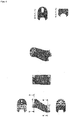
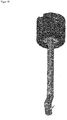
Fig 1 : Beschichtungslanze -
Fig.: 2 Manuelle Lötvertigungszeichnung -
Fig.: 3 Additiv gefertigter Plasmakopf aus einer Kupferlegierung -
Fig.: 4 Additive gefertigter Plasmakopf im Detail (innen liegend geschwungene Bohrungen) -
Fig.: 5 Additive gefertigter Minuspol aus Kupferlegierung -
Fig.: 6 Tieflochgebohrte Lanze -
Fig.: 7 Heirat Plasmakopf, Minuspol und Lanze -
Fig.: 8 Lateralversatz um Distanz zur Zylinderwand beizubehalten -
Fig.: 9 Lateralversatz nur am Brennerkopf -
Fig.: 10 Beschichtung -
Fig.: 11 Unzureichende Profilfüllung durch nicht rechtwinkliges Auftreffen der Partikel (Schatteneffekt) -
Fig.: 12 Ausreichend gefüllte Profilfüllung der Hinterschnitte -
Fig.: 13 Winkelkorrektur -
Fig.: 14 Gasgekühlte Anode (Rohrprofil Kupferlegierung, Minuspol additiv gefertigt, Isolation (schwarz), Isolation Anode - Kathode (weiss)) -
Fig.: 15 F210 RotaCoupler™ Centerline - Die Erfindung betrifft eine Beschichtungslanze für einen Plasmaprozess und ein Verfahren zur Herstellung einer Beschichtungslanze gemäß den angehängten Ansprüchen 1-6.
- Durch das Fertigungsverfahren des Additive Manufacturing entstehen neue Möglichkeiten in der konstruktiven Designphase. Jedwede Form kann erstellt und gefertigt werden. Durch diesen Vorteil lassen sich unabhängig von konventionellen Methoden sehr kompakte Bauteile mit Freiformflächen fertigen. (
Fig.:3 ). Gerade Bohrungen, die bislang in runder Ausführung erstellt werden mussten, oder mühevoll mit teuren Fertigungswerkzeugen herauserodiert werden mussten, und nur in gerader Ausführung möglich waren, können in der additiven Fertigung jede geometrische Ausführung haben. Ein weiterer Vorteil ist die "Bohrung um die Ecke", wodurch Bohrungen in Kurvenbahnen aneinander vorbei oder sich in unterschiedlichen Eben kreuzen aber nicht schneidend ausgeführt werden können. Durch diese Vorteile können optimierte Leitungsführungen und optimale Materialausnutzung gewährleistet werden, wodurch eine Miniaturisierung der Brennerlanze gewährleistet werden kann. (Fig.: 4 ) - Es wäre technisch möglich die gesamte Lanze durch das additive Verfahren zu fertigen, allerdings ist das bis heute unwirtschaftlich und aktuell nicht notwendig. Aus diesem Grund wird hier lediglich der Plasmakopf (
Fig.: 4 ) und der Minuspol (Fig.: 5 ) am Plasmakopf durch das additive Fertigen erstellt. In Verbindung mit der additiven Fertigung kommt das Fertigungsverfahren des "Tieflochbohrens" zum Einsatz, um den Schaft der Lanze auszubilden. Dieses Verfahren ist in Verbindung mit dem Bohrungsdurchmesser längenlimitiert. Um das aufzufangen, können mehrere tieflochgebohrte Schäfte (Fig.: 6 ) aneinander gereiht und verschraubt werden. Theoretisch gäbe es dadurch keine Limitierung der Lanzenlänge. Um die Beschichtungslanze fertigzustellen werden der additiv gefertigte Plasmakopf Komponenten und die tieflochgebohrte Lanze miteinander verschraubt. (Fig.: 7 ) - In der Vergangenheit wurde die Beschichtungslanze durch die zuvor beschriebenen Fertigungsverfahren hergestellt. Bei dem RotaPlasma® Prozess handelt es sich um einen rotativen Beschichtungsprozess. Eine Drehdurchführung befördert die Medien vom stationären Anschluss zu einer endlos rotierenden Welle. An dieses Wellenende wird eine Plasmalanze adaptiert, wodurch eine Innenbeschichtung von zum Beispiel Zylinderlaufflächen eins Motorblocks beschichtet werden können.
- Bei der Beschichtung eines Substrates müssen eine Oberflächengeschwindigkeit und eine gewisse Distanz eingehalten werden. Bei der Rotation der Lanze einem Vorschub in Bohrungsachsrichtung und dem zuvor beschriebenen Schmelzvorgang entsteht so ein Schichtaufbau an der Substratoberfläche. Hierbei bleibt die Distanz zwischen Plasmaaustritt und Substratoberfläche konstant. Da die Achse der drehenden Welle des RotaPlasma® koaxial zur Rotationsachse der Bohrung angeordnet ist, muss der Plasmakopf bei einer grösseren zu beschichtenden Bohrung lateral zur Bohrungsachse ausgelenkt werden. Bei früheren Ausführungen wurde die gesamte Plasmalanze lateral ausgelenkt, wodurch bei der erhöhten Rotationsgeschwindigkeit starke Fliehkräfte erzeugt wurden. Diese Fliehkräfte erzeugten ungewollte Schwingungen und Belastungen auf das Antriebssystem aber auch auf die Schichtqualität am Substrat. Um den Fliehkräften entgegenzuwirken, wurden Gegengewichte angebracht, um die Unwucht des lateralen Versatzes dynamisch Auszuwuchten. Da, wie zuvor beschrieben die gesamte Lanze lateral verschoben wurde, wurde eine enorme Unwucht hervorgerufen. (
Fig.: 8 ) - Aufgrund der zuvor beschriebenen Fertigungsmethoden der neuen Beschichtungslanze, wird lediglich der Plasmakopf lateral ausgelenkt. Die Lanze bleibt koaxial zur rotierenden Welle des RotaPlasma® angeordnet. Durch diese Methode wird nur ein kleiner Massenschwerpunkt der Beschichtungslanze aus der Drehachse lateral versetzt, wodurch eine signifikante Reduzierung der Fliehkraft und der damit resultierenden dynamischen Unwucht erzeugt wird. Als Folge dessen, ist eine Reduzierung der Auswuchtgewichte gewährleistet. So ist nahezu jede Distanz zwischen Plasmaaustritt und Substratoberfläche möglich. (
Fig.: 9 ) Ein weiterer Vorteil der neuen Fertigungsverfahren ist gleichbleibende Massenpunkte aller Komponenten. Nachdem eine Lanze gefertigt wurde, wird die Unwucht gemessen, und die Gegengewichte hergestellt. Jede weitere Plasmalanze mit gleichbleibendem Lateralversatz kann mit den zuvor definierten Gewichten ausgewuchtet werden. Im Vergleich zur konventionellen Herstellung (Handarbeit) war jede Lanze ein Einzelstück, und war nur sehr erschwert und ungenau automatisiert Auswuchtbar. D.h. Lanze eins wurde mit lateral Versatz x gefertigt, anschliessend wurden auf einer Wuchtmaschine die Unwucht ermittelt und die Gegengewichte definiert um diese zu Fertigen und an der Lanze zu befestigen. Wurde später Lanze zwei gefertigt mit demselben lateralen Versatz wie Lanze eins, so wies Lanze zwei nicht dieselbe Unwucht auf. Dies erschwerte eine automatisierte Kleinserienfertigung der Plasmalanzen. Die Ungenauigkeit resultiert aus der Toleranzsummierung der Handarbeit in den vorgelagerten Prozessen. Im Gegensatz hierzu sind die neuen Fertigungsverfahren um ein vielfaches präziser und gleichbleibend. - Um eine Haftung zwischen aufgeschmolzenen Partikeln und Substrat bei der Beschichtung (
Fig.: 10 ) zu erreichen, muss die Oberfläche des Werkstückes vorbehandelt werden. Hierbei bekannt sind mechanische und thermische Verfahren. Entscheidend bei allen Verfahren ist ein generieren von Hinterschnitten auf der Werkstückoberfläche, um ein Verklammerung zwischen Substrat und aufgeschmolzenen Partikeln zu erreichen. Thermische Verfahren sind hierbei das Laseraktivieren. Dem gegenüber stehen die mechanischen Verfahren der Aktivierung: Korundstrahlen, pulsierendem Wasserstahl und dem mechanischem Schneidwerkzeug. Durch das Korund- sowie dem pulsierendem Wasserstahlaktivieren resultiert eine chaotisch ungeordnet stochastische Hinterschnittgeometrie. Im Gegensatz hierzu erzeugt die Schneidplatten beim Schneidwerkzeug durch eine Rotation und dem Vorschub eine spiralförmige Kontur. Die Schneidgeometrie ist ähnlich einem Schwalbenschwanz ausgeführt, wodurch geordnete Hinterschnitte erzeugt werden. Anders als bei den zuvor beschriebenen Verfahren der Aktivierung bedingt diese Ausführung ein nahezu rechtwinkliges Auftreffen der aufgeschmolzenen Partikel, um ein unvollständig gefüllte Profilfüllung (Fig.: 11 ) zu verhindern und eine vollständige Füllung des Schwalbenschwanzgrundes (Fig.: 12 ) zu erreichen. Nur dann kann eine ausreichende Verklammerung entstehen. - In dem zuvor beschriebenen neuen Fertigungsverfahren, sind die Geometrien des Plasmakopfes frei wählbar. Die Richtung Bewegungsrichtung der aufgeschmolzenen Partikel wird durch den Plasmastrahl beeinflusst und umgelenkt. Gerade, bei einer Injektion von oben, wird der Plasmastrahl allerdings durch die mechanische Energie des Pulver-Gas-Gemisches nach unten abgelenkt. Gerade bei erhöhten Förderraten ist dies sehr auffallend. Um diesem Phänomen entgegenzuwirken und die Flugbahn der Partikel und den damit verbunden Auftreffwinkel auf 90° zur Substratoberfläche zu korrigieren, muss der Winkel des Plasmaaustritts korrigiert werden. (
Fig.: 13 ) Winkelkorrektur - α =0°
Lanze und Plasmakopf vertikal ausgerichtet - -90° < α < 0°
Lanze Vertikal, Plasmakopf α < 0° angestellt - Um ein Plasma zu erzeugen ist neben einem Gasgemisch das Erzeugen eines Lichtbogens erforderlich. Hierzu werden die Kathode und Anode elektrisch zueinander isoliert bis zum Plasmakopf geführt. Durch ein Zündfunke im kV Bereich springt ein Lichtbogen von der Kathode zur Anode. Dadurch werden das Gasgemisch und der Lichtbogen in ein Plasma überführt. Dabei reduziert sich die Spannung schlagartig und analog dazu springt die Stromstärke in die Höhe. Dadurch entsteht durch die Einleitung der Stromstärke im 300 - 600 A Bereich und dem resultierendem Übergangswiderstand eine enorme thermische Strombelastung der Kathode und Anode. In älteren Ausführungen der Plasmalanzen für Innenbeschichtungen waren die Stromstärke und damit die Plasmaleistung limitiert. Die Flächenbelastung der kleinen Plasmalanze im speziellen der Kathode stellte hierbei eine erhebliche Schwachstelle dar. Bei der Anode war dieses Phänomen weniger kritisch, da diese Wassergekühlt ausgeführt werden konnte. Um die Strombelastung der Kathodenschiene zu reduzieren, ist die Kathode (Minuspol) aktiv gekühlt. Dies geschieht durch das für den Plasmaprozess notwendigen Gasgemisches. Das Plasmagasgemisch wird hierbei über ein Rohrprofil zur Kathode geführt, dort mit dem additiv gefertigten Minuspol verbunden. (
Fig.: 14 ) - Dabei ist der Minuspol konstruktiv so ausgeführt, dass innenliegend eine Eingangsbohrung zu zwei Kühladern im inneren der Kathode verlaufen. Dadurch wird die Kathode aktiv durch das Plasmagas gekühlt und die Strombelastung signifikant herabgesetzt.
- Es wurde eine Beschichtungslanze für einen Plasmaprozess offenbart
wobei die Lanze einen Plasmaschaft, einen Plasmahals und einen Plasmakopf umfasst wobei der Plasmaschaft einen Längskanal umfasst welcher sich in einer axialen Richtung entlang einer Achse von einem ersten Schaftende bis zu einem zweiten Schaftende erstreckt
wobei der Plasmahals einen Schaftansatz und einen Kopfansatz und zumindest einen Halskanal umfasst der vom Schaftansatz zum Kopfansatz verläuft und der Schaftansatz am zweiten Schaftende angeordnet ist dergestalt, dass der Längskanal in den zumindest einen Halskanal einmündet
wobei der Plasmakopf einen Halsansatz, eine Plasmaöffnung und zumindest einen Kopfkanal umfasst der vom Halsansatz bis zur Plasmaöffnung verläuft und der Halsansatz des Plasmakopfes am Kopfansatz des Plasmahalses angeordnet ist dergestallt, dass der zumindest eine Halskanal in den Kopfkanal einmündet. Der Verlauf des Plasmakanals weicht derart von der Achse ab dass der Halskanal bzgl. der Achse nicht zentriert, d.h. gegenüber der Achse versetzt in den Kopfkanal einmündet. - Der Plasmahals ist vorzugsweise lösbar am zweiten Schaftende fixiert ist. Besonders bevorzugt ist der Plasmakopf ebenfalls lösbar am Plasmahals fixiert.
- Der Halskanal weisst bevorzugt zumindest eine Krümmung auf besonders bevorzugt zumindest zwei Krümmungen mit unterschiedlichem Vorzeichen.
- Die durch den Rand der Plasmaöffnung definierte Ebene kann mit Vorteil gegenüber der Achse um einen Winkel α < 0° angestellt sein
- Es wurde ein Verfahren zur Herstellung eine Beschichtungslanze wie oben beschrieben offenbart, wobei zumindest der Plasmahals, vorzugsweise auch der Plasmakopf mittels eines additiven Herstellungsverfahrens, bevorzugt durch schichtweisen Aufbau hergestellt wird.
- Der Längskanal im Plasmaschaft kann zumindest teilsweise vorzugsweise vollständig mittels tieflochbohren hergestellt werden.
Claims (6)
- Beschichtungslanze für einen Plasmaprozess,
wobei die Lanze einen Plasmaschaft, einen Plasmahals und einen Plasmakopf umfasst wobei der Plasmaschaft einen Längskanal umfasst welcher sich in einer axialen Richtung entlang einer Achse von einem ersten Schaftende bis zu einem zweiten Schaftende erstreckt;
wobei der Plasmahals einen Schaftansatz und einen Kopfansatz und zumindest einen Halskanal umfasst der vom Schaftansatz zum Kopfansatz verläuft und der Schaftansatz am zweiten Schaftende angeordnet ist dergestalt, dass der Längskanal in den zumindest einen Halskanal einmündet;
wobei der Plasmakopf einen Halsansatz, eine Plasmaöffnung, und zumindest einen Kopfkanal umfasst der vom Halsansatz bis zur Plasmaöffnung verläuft, und der Halsansatz des Plasmakopfes am Kopfansatz des Plasmahalses angeordnet ist dergestallt, dass der zumindest eine Halskanal in den Kopfkanal einmündet, dadurch gekennzeichnet, dass
der Verlauf des Plasmakanals derart von der Achse abweicht, dass der Halskanal bzgl. der Achse nicht zentriert, d.h. gegenüber der Achse versetzt in den Kopfkanal einmündet - Beschichtungslanze nach Anspruch 1, dadurch gekennzeichnet, dass der Plasmahals lösbar am zweiten Schaftende fixiert ist.
- Beschichtungslanze nach einem der vorangehenden Ansprüche, dadurch gekennzeichnet, dass der Halskanal zumindest eine Krümmung aufweist und vorzugsweise zumindest zwei Krümmungen mit unterschiedlichem Vorzeichen aufweiset
- Beschichtungslanze nach einem der vorangehenden Ansprüche, dadurch gekennzeichnet, dass die durch den Rand der Plasmaöffnung definierte Ebene gegenüber der Achse um einen Winkel α < 0° angestellt ist.
- Verfahren zur Herstellung einer Beschichtungslanze gemäss einem der vorangehenden Ansprüche, dadurch gekennzeichnet, dass zumindest der Plasmahals, vorzugsweise auch der Plasmakopf mittels eines additiven Herstellungsverfahrens, bevorzugt durch schichtweisen Aufbau hergestellt wird.
- Verfahren nach Anspruch 5, dadurch gekennzeichnet, dass der Längskanal im Plasmaschaft zumindest teilweise mittels Tieflochbohren hergestellt wird.
Priority Applications (1)
| Application Number | Priority Date | Filing Date | Title |
|---|---|---|---|
| PL18730975T PL3631037T3 (pl) | 2017-05-29 | 2018-05-29 | Powlekająca lanca plazmowa do powłok wewnętrznych |
Applications Claiming Priority (2)
| Application Number | Priority Date | Filing Date | Title |
|---|---|---|---|
| EP17000902 | 2017-05-29 | ||
| PCT/EP2018/000276 WO2018219497A1 (de) | 2017-05-29 | 2018-05-29 | Plasma-beschichtungslanze für innenbeschichtungen |
Publications (2)
| Publication Number | Publication Date |
|---|---|
| EP3631037A1 EP3631037A1 (de) | 2020-04-08 |
| EP3631037B1 true EP3631037B1 (de) | 2021-03-24 |
Family
ID=59067441
Family Applications (1)
| Application Number | Title | Priority Date | Filing Date |
|---|---|---|---|
| EP18730975.2A Active EP3631037B1 (de) | 2017-05-29 | 2018-05-29 | Plasma-beschichtungslanze für innenbeschichtungen |
Country Status (14)
| Country | Link |
|---|---|
| US (1) | US11866826B2 (de) |
| EP (1) | EP3631037B1 (de) |
| JP (1) | JP7210477B2 (de) |
| KR (1) | KR102604926B1 (de) |
| CN (1) | CN110914466A (de) |
| AU (1) | AU2018277057B2 (de) |
| BR (1) | BR112019024994B1 (de) |
| ES (1) | ES2868176T3 (de) |
| HU (1) | HUE054154T2 (de) |
| MX (1) | MX2019014335A (de) |
| MY (1) | MY205318A (de) |
| PL (1) | PL3631037T3 (de) |
| RU (1) | RU2019143076A (de) |
| WO (1) | WO2018219497A1 (de) |
Cited By (3)
| Publication number | Priority date | Publication date | Assignee | Title |
|---|---|---|---|---|
| EP4400219A1 (de) | 2023-01-13 | 2024-07-17 | Volkswagen Ag | Düsenplatte für eine plasmaspritzmaschine zum atmosphärischen plasmaspritzen sowie plasmaspritzmaschine |
| DE102023113188A1 (de) * | 2023-05-19 | 2024-11-21 | Sms Group Gmbh | Vorrichtung zum thermischen Spritzen, Fertigungsverfahren zum Fertigen einer derartigen Vorrichtung und Verwendung eines additiven Fertigungsverfahrens |
| DE102024117476A1 (de) * | 2024-06-20 | 2025-12-24 | Sms Group Gmbh | Kathodenteil, Anodenteil, Zuführeinrichtung, Vorrichtung zum thermischen Spritzen, Verfahren zum Herstellen eines derartigen Kathodenteils und/oder Anodenteils, Verfahren zum Betreiben einer Vorrichtung zum thermischen Spritzen, Verwendung eines Kathodenteils, Verwendung eines Anodenteils und Verwendung einer Zuführvorrichtung von Pulverpartikeln |
Families Citing this family (4)
| Publication number | Priority date | Publication date | Assignee | Title |
|---|---|---|---|---|
| US11866826B2 (en) | 2017-05-29 | 2024-01-09 | Oerlikon Metco Ag, Wohlen | Plasma coating lance for internal coatings |
| CN109440054B (zh) * | 2018-12-25 | 2024-01-30 | 中国人民解放军陆军装甲兵学院 | 一种用于旋转式内孔等离子喷涂的柔性快装转接体 |
| JP2023037789A (ja) * | 2021-09-06 | 2023-03-16 | 株式会社ジェイテクト | 皮膜を形成する方法 |
| DE102023000417A1 (de) | 2023-02-07 | 2024-08-08 | Oerlikon Metco (Us) Inc. | Plasma-Brennerkopf für Innenbeschichtungen |
Family Cites Families (19)
| Publication number | Priority date | Publication date | Assignee | Title |
|---|---|---|---|---|
| US3750339A (en) * | 1971-12-20 | 1973-08-07 | Carborundum Co | Pipe cleaning apparatus |
| DE3642375A1 (de) | 1986-12-11 | 1988-06-23 | Castolin Sa | Verfahren zur aufbringung einer innenbeschichtung in rohre od. dgl. hohlraeume engen querschnittes sowie plasmaspritzbrenner dafuer |
| DE3645235A1 (de) * | 1986-12-11 | 1992-03-19 | Castolin Sa | Verfahren zum innenbeschichten eines rohres durch plasmaspritzen |
| US4912296A (en) * | 1988-11-14 | 1990-03-27 | Schlienger Max P | Rotatable plasma torch |
| US5271967A (en) * | 1992-08-21 | 1993-12-21 | General Motors Corporation | Method and apparatus for application of thermal spray coatings to engine blocks |
| DE4228064A1 (de) | 1992-08-24 | 1994-03-03 | Plasma Technik Ag | Plasmaspritzgerät |
| DE4240991A1 (de) * | 1992-12-05 | 1994-06-09 | Plasma Technik Ag | Plasmaspritzgerät |
| RU2075535C1 (ru) | 1995-01-31 | 1997-03-20 | Институт теоретической и прикладной механики СО РАН | Установка для нанесения покрытия на внутреннюю поверхность трубы |
| RU2181390C2 (ru) | 2000-06-06 | 2002-04-20 | Дикун Юрий Вениаминович | Установка для газодинамического нанесения покрытия из порошковых материалов |
| TW200308187A (en) | 2002-04-10 | 2003-12-16 | Dow Corning Ireland Ltd | An atmospheric pressure plasma assembly |
| JP4496783B2 (ja) * | 2004-01-16 | 2010-07-07 | トヨタ自動車株式会社 | 溶射装置と溶射方法 |
| RU2278904C1 (ru) | 2004-11-26 | 2006-06-27 | Общество с ограниченной ответственностью научно-производственная фирма региональный плазмотехнический центр "ПЛАЗТЕХ" | Установка для напыления газотермических покрытий |
| US7928338B2 (en) * | 2007-02-02 | 2011-04-19 | Plasma Surgical Investments Ltd. | Plasma spraying device and method |
| JP5334325B2 (ja) * | 2010-04-16 | 2013-11-06 | ユニクラフトナグラ株式会社 | 中空部品の深穴成形装置及び成形法 |
| DE102013007737B4 (de) * | 2013-05-07 | 2017-03-09 | Britta Rossen | Beschichtungsvorrichtung zum thermischen Beschichten |
| DE102014010665A1 (de) | 2014-07-18 | 2016-01-21 | GM Global Technology Operations LLC (n. d. Ges. d. Staates Delaware) | Beschichtung einer Kolbenlauffläche einer Zylinderbohrung einer Brennkraftmaschine eines Kraftfahrzeugs |
| CN109475885B (zh) * | 2016-05-27 | 2022-03-08 | 欧瑞康美科股份公司,沃伦 | 覆层方法、热覆层以及具有热覆层的缸 |
| JP6803021B2 (ja) * | 2016-10-25 | 2020-12-23 | 株式会社ダイヘン | 積層造形物の製造方法および積層造形物 |
| US11866826B2 (en) | 2017-05-29 | 2024-01-09 | Oerlikon Metco Ag, Wohlen | Plasma coating lance for internal coatings |
-
2018
- 2018-05-29 US US16/617,036 patent/US11866826B2/en active Active
- 2018-05-29 RU RU2019143076A patent/RU2019143076A/ru unknown
- 2018-05-29 KR KR1020197038424A patent/KR102604926B1/ko active Active
- 2018-05-29 WO PCT/EP2018/000276 patent/WO2018219497A1/de not_active Ceased
- 2018-05-29 HU HUE18730975A patent/HUE054154T2/hu unknown
- 2018-05-29 JP JP2019565798A patent/JP7210477B2/ja active Active
- 2018-05-29 MX MX2019014335A patent/MX2019014335A/es unknown
- 2018-05-29 EP EP18730975.2A patent/EP3631037B1/de active Active
- 2018-05-29 MY MYPI2019006990A patent/MY205318A/en unknown
- 2018-05-29 PL PL18730975T patent/PL3631037T3/pl unknown
- 2018-05-29 AU AU2018277057A patent/AU2018277057B2/en active Active
- 2018-05-29 BR BR112019024994-0A patent/BR112019024994B1/pt active IP Right Grant
- 2018-05-29 CN CN201880035378.1A patent/CN110914466A/zh active Pending
- 2018-05-29 ES ES18730975T patent/ES2868176T3/es active Active
Non-Patent Citations (1)
| Title |
|---|
| None * |
Cited By (4)
| Publication number | Priority date | Publication date | Assignee | Title |
|---|---|---|---|---|
| EP4400219A1 (de) | 2023-01-13 | 2024-07-17 | Volkswagen Ag | Düsenplatte für eine plasmaspritzmaschine zum atmosphärischen plasmaspritzen sowie plasmaspritzmaschine |
| DE102023200269A1 (de) | 2023-01-13 | 2024-07-18 | Volkswagen Aktiengesellschaft | Düsenplatte für eine Plasmaspritzmaschine zum atmosphärischen Plasmaspritzen sowie Plasmaspritzmaschine |
| DE102023113188A1 (de) * | 2023-05-19 | 2024-11-21 | Sms Group Gmbh | Vorrichtung zum thermischen Spritzen, Fertigungsverfahren zum Fertigen einer derartigen Vorrichtung und Verwendung eines additiven Fertigungsverfahrens |
| DE102024117476A1 (de) * | 2024-06-20 | 2025-12-24 | Sms Group Gmbh | Kathodenteil, Anodenteil, Zuführeinrichtung, Vorrichtung zum thermischen Spritzen, Verfahren zum Herstellen eines derartigen Kathodenteils und/oder Anodenteils, Verfahren zum Betreiben einer Vorrichtung zum thermischen Spritzen, Verwendung eines Kathodenteils, Verwendung eines Anodenteils und Verwendung einer Zuführvorrichtung von Pulverpartikeln |
Also Published As
| Publication number | Publication date |
|---|---|
| KR20200021942A (ko) | 2020-03-02 |
| MX2019014335A (es) | 2020-08-03 |
| KR102604926B1 (ko) | 2023-11-21 |
| JP7210477B2 (ja) | 2023-01-23 |
| WO2018219497A1 (de) | 2018-12-06 |
| BR112019024994A2 (pt) | 2020-06-16 |
| AU2018277057B2 (en) | 2023-10-12 |
| CA3065141A1 (en) | 2018-12-06 |
| CN110914466A (zh) | 2020-03-24 |
| MY205318A (en) | 2024-10-12 |
| AU2018277057A1 (en) | 2019-12-19 |
| HUE054154T2 (hu) | 2021-08-30 |
| PL3631037T3 (pl) | 2021-09-06 |
| RU2019143076A3 (de) | 2021-09-29 |
| US20200255942A1 (en) | 2020-08-13 |
| JP2020526659A (ja) | 2020-08-31 |
| RU2019143076A (ru) | 2021-06-30 |
| ES2868176T3 (es) | 2021-10-21 |
| US11866826B2 (en) | 2024-01-09 |
| BR112019024994B1 (pt) | 2023-02-07 |
| EP3631037A1 (de) | 2020-04-08 |
Similar Documents
| Publication | Publication Date | Title |
|---|---|---|
| EP3631037B1 (de) | Plasma-beschichtungslanze für innenbeschichtungen | |
| DE19508687C2 (de) | Verfahren zur Herstellung einer verschleißfesten Beschichtung auf einer Zylinderinnenwand und seine Anwendung | |
| DE69504944T2 (de) | Verfahren zur Herstellung von Motorblöcken mit beschichteten Zylinderbohrungen | |
| DE10256460B4 (de) | Verfahren zum Herstellen eines Produkts mit einem aufgesprühten Beschichtungsfilm und Sprühpistoleneinrichtung | |
| DE102005005359A1 (de) | Verfahren zum Kaltgasspritzen und für dieses Verfahren geeignete Beschichtungsanlage | |
| EP3741031A1 (de) | Verfahren zur herstellung eines käfigläufers | |
| DE4030541A1 (de) | Brenner zur beschichtung von grundwerkstoffen mit pulverfoermigen zusatzwerkstoffen | |
| JP2017506303A (ja) | 被覆されたピンボアを備えたピストン | |
| WO2008104252A1 (de) | Verfahren zum substratbeschichten durch thermisches oder kinetisches spritzen | |
| DE102012018286A1 (de) | Kaltschweißverfahren und Kaltschweißvorrichtung | |
| EP3972774A1 (de) | ELEKTRONENSTRAHLSCHWEIßEN VON NICKELBASIS-SUPERLEGIERUNGEN UND VORRICHTUNG | |
| DE102008053641B3 (de) | Thermisch gespritzte Zylinderlaufbahnbeschichtung, Verfahren zu deren Herstellung sowie deren Verwendung in Verbrennungsmotoren | |
| EP2816135B1 (de) | Plasmapulverspritzverfahren zur Beschichtung von Paneelen für Kesselwände in Verbindung mit einem Laserstrahlgerät | |
| CN105829570A (zh) | 用于hvof喷涂工艺的装置 | |
| CA3065141C (en) | A plasma coating lance for internal coatings | |
| DE10064440B4 (de) | Verfahren und eine Vorrichtung zum Bearbeiten einer Innenfläche einer zylinderförmigen Bohrung eines Bauteils | |
| DE10041114A1 (de) | Verfahren zur Beseitigung von Beschichtungs-und/oder Erosionsschäden | |
| DE112014004111T5 (de) | Drahtlegierung für Plasma-Lichtbogen-Beschichtung | |
| EP3896190B1 (de) | Verfahren und anlage zur metallischen beschichtung einer bohrungswand | |
| DE10328450A1 (de) | Verfahren zur Beseitigung von Beschichtungs- und/oder Erosionsschäden | |
| EP1748856B1 (de) | Nockenwelle und ein verfahren zu deren herstellung | |
| DE102022105774A1 (de) | Verfahren zum Bearbeiten eines Kurbelgehäuses sowie Kurbelgehäuse | |
| DE102023000417A1 (de) | Plasma-Brennerkopf für Innenbeschichtungen | |
| DE202022000408U1 (de) | Stoffschlüssige Verbindung artungleicher, metallischer Werkstoffe mittels Elektronenstrahl insbesondere von Stahl mit Titan sowie Aluminium mit Kupfer | |
| DE102012105607A1 (de) | Verfahren zur Herstellung von Komposit-Spritzschichten auf Zylinderlaufflächen von Zylinderkurbelgehäusen |
Legal Events
| Date | Code | Title | Description |
|---|---|---|---|
| STAA | Information on the status of an ep patent application or granted ep patent |
Free format text: STATUS: UNKNOWN |
|
| STAA | Information on the status of an ep patent application or granted ep patent |
Free format text: STATUS: THE INTERNATIONAL PUBLICATION HAS BEEN MADE |
|
| PUAI | Public reference made under article 153(3) epc to a published international application that has entered the european phase |
Free format text: ORIGINAL CODE: 0009012 |
|
| STAA | Information on the status of an ep patent application or granted ep patent |
Free format text: STATUS: REQUEST FOR EXAMINATION WAS MADE |
|
| 17P | Request for examination filed |
Effective date: 20200102 |
|
| AK | Designated contracting states |
Kind code of ref document: A1 Designated state(s): AL AT BE BG CH CY CZ DE DK EE ES FI FR GB GR HR HU IE IS IT LI LT LU LV MC MK MT NL NO PL PT RO RS SE SI SK SM TR |
|
| AX | Request for extension of the european patent |
Extension state: BA ME |
|
| DAV | Request for validation of the european patent (deleted) | ||
| DAX | Request for extension of the european patent (deleted) | ||
| GRAP | Despatch of communication of intention to grant a patent |
Free format text: ORIGINAL CODE: EPIDOSNIGR1 |
|
| STAA | Information on the status of an ep patent application or granted ep patent |
Free format text: STATUS: GRANT OF PATENT IS INTENDED |
|
| INTG | Intention to grant announced |
Effective date: 20201023 |
|
| GRAS | Grant fee paid |
Free format text: ORIGINAL CODE: EPIDOSNIGR3 |
|
| GRAA | (expected) grant |
Free format text: ORIGINAL CODE: 0009210 |
|
| STAA | Information on the status of an ep patent application or granted ep patent |
Free format text: STATUS: THE PATENT HAS BEEN GRANTED |
|
| AK | Designated contracting states |
Kind code of ref document: B1 Designated state(s): AL AT BE BG CH CY CZ DE DK EE ES FI FR GB GR HR HU IE IS IT LI LT LU LV MC MK MT NL NO PL PT RO RS SE SI SK SM TR |
|
| REG | Reference to a national code |
Ref country code: GB Ref legal event code: FG4D Free format text: NOT ENGLISH |
|
| REG | Reference to a national code |
Ref country code: CH Ref legal event code: EP |
|
| REG | Reference to a national code |
Ref country code: DE Ref legal event code: R096 Ref document number: 502018004471 Country of ref document: DE |
|
| REG | Reference to a national code |
Ref country code: IE Ref legal event code: FG4D Free format text: LANGUAGE OF EP DOCUMENT: GERMAN |
|
| REG | Reference to a national code |
Ref country code: AT Ref legal event code: REF Ref document number: 1374602 Country of ref document: AT Kind code of ref document: T Effective date: 20210415 |
|
| REG | Reference to a national code |
Ref country code: SE Ref legal event code: TRGR |
|
| REG | Reference to a national code |
Ref country code: NL Ref legal event code: FP |
|
| REG | Reference to a national code |
Ref country code: LT Ref legal event code: MG9D |
|
| PG25 | Lapsed in a contracting state [announced via postgrant information from national office to epo] |
Ref country code: NO Free format text: LAPSE BECAUSE OF FAILURE TO SUBMIT A TRANSLATION OF THE DESCRIPTION OR TO PAY THE FEE WITHIN THE PRESCRIBED TIME-LIMIT Effective date: 20210624 Ref country code: BG Free format text: LAPSE BECAUSE OF FAILURE TO SUBMIT A TRANSLATION OF THE DESCRIPTION OR TO PAY THE FEE WITHIN THE PRESCRIBED TIME-LIMIT Effective date: 20210624 Ref country code: GR Free format text: LAPSE BECAUSE OF FAILURE TO SUBMIT A TRANSLATION OF THE DESCRIPTION OR TO PAY THE FEE WITHIN THE PRESCRIBED TIME-LIMIT Effective date: 20210625 Ref country code: FI Free format text: LAPSE BECAUSE OF FAILURE TO SUBMIT A TRANSLATION OF THE DESCRIPTION OR TO PAY THE FEE WITHIN THE PRESCRIBED TIME-LIMIT Effective date: 20210324 Ref country code: HR Free format text: LAPSE BECAUSE OF FAILURE TO SUBMIT A TRANSLATION OF THE DESCRIPTION OR TO PAY THE FEE WITHIN THE PRESCRIBED TIME-LIMIT Effective date: 20210324 |
|
| REG | Reference to a national code |
Ref country code: HU Ref legal event code: AG4A Ref document number: E054154 Country of ref document: HU |
|
| PG25 | Lapsed in a contracting state [announced via postgrant information from national office to epo] |
Ref country code: RS Free format text: LAPSE BECAUSE OF FAILURE TO SUBMIT A TRANSLATION OF THE DESCRIPTION OR TO PAY THE FEE WITHIN THE PRESCRIBED TIME-LIMIT Effective date: 20210324 Ref country code: LV Free format text: LAPSE BECAUSE OF FAILURE TO SUBMIT A TRANSLATION OF THE DESCRIPTION OR TO PAY THE FEE WITHIN THE PRESCRIBED TIME-LIMIT Effective date: 20210324 |
|
| REG | Reference to a national code |
Ref country code: ES Ref legal event code: FG2A Ref document number: 2868176 Country of ref document: ES Kind code of ref document: T3 Effective date: 20211021 |
|
| PG25 | Lapsed in a contracting state [announced via postgrant information from national office to epo] |
Ref country code: LT Free format text: LAPSE BECAUSE OF FAILURE TO SUBMIT A TRANSLATION OF THE DESCRIPTION OR TO PAY THE FEE WITHIN THE PRESCRIBED TIME-LIMIT Effective date: 20210324 Ref country code: EE Free format text: LAPSE BECAUSE OF FAILURE TO SUBMIT A TRANSLATION OF THE DESCRIPTION OR TO PAY THE FEE WITHIN THE PRESCRIBED TIME-LIMIT Effective date: 20210324 Ref country code: SM Free format text: LAPSE BECAUSE OF FAILURE TO SUBMIT A TRANSLATION OF THE DESCRIPTION OR TO PAY THE FEE WITHIN THE PRESCRIBED TIME-LIMIT Effective date: 20210324 |
|
| PG25 | Lapsed in a contracting state [announced via postgrant information from national office to epo] |
Ref country code: IS Free format text: LAPSE BECAUSE OF FAILURE TO SUBMIT A TRANSLATION OF THE DESCRIPTION OR TO PAY THE FEE WITHIN THE PRESCRIBED TIME-LIMIT Effective date: 20210724 Ref country code: RO Free format text: LAPSE BECAUSE OF FAILURE TO SUBMIT A TRANSLATION OF THE DESCRIPTION OR TO PAY THE FEE WITHIN THE PRESCRIBED TIME-LIMIT Effective date: 20210324 Ref country code: PT Free format text: LAPSE BECAUSE OF FAILURE TO SUBMIT A TRANSLATION OF THE DESCRIPTION OR TO PAY THE FEE WITHIN THE PRESCRIBED TIME-LIMIT Effective date: 20210726 Ref country code: SK Free format text: LAPSE BECAUSE OF FAILURE TO SUBMIT A TRANSLATION OF THE DESCRIPTION OR TO PAY THE FEE WITHIN THE PRESCRIBED TIME-LIMIT Effective date: 20210324 |
|
| REG | Reference to a national code |
Ref country code: DE Ref legal event code: R097 Ref document number: 502018004471 Country of ref document: DE |
|
| PG25 | Lapsed in a contracting state [announced via postgrant information from national office to epo] |
Ref country code: DK Free format text: LAPSE BECAUSE OF FAILURE TO SUBMIT A TRANSLATION OF THE DESCRIPTION OR TO PAY THE FEE WITHIN THE PRESCRIBED TIME-LIMIT Effective date: 20210324 Ref country code: AL Free format text: LAPSE BECAUSE OF FAILURE TO SUBMIT A TRANSLATION OF THE DESCRIPTION OR TO PAY THE FEE WITHIN THE PRESCRIBED TIME-LIMIT Effective date: 20210324 Ref country code: MC Free format text: LAPSE BECAUSE OF FAILURE TO SUBMIT A TRANSLATION OF THE DESCRIPTION OR TO PAY THE FEE WITHIN THE PRESCRIBED TIME-LIMIT Effective date: 20210324 Ref country code: LU Free format text: LAPSE BECAUSE OF NON-PAYMENT OF DUE FEES Effective date: 20210529 |
|
| PLBE | No opposition filed within time limit |
Free format text: ORIGINAL CODE: 0009261 |
|
| STAA | Information on the status of an ep patent application or granted ep patent |
Free format text: STATUS: NO OPPOSITION FILED WITHIN TIME LIMIT |
|
| REG | Reference to a national code |
Ref country code: BE Ref legal event code: MM Effective date: 20210531 |
|
| PG25 | Lapsed in a contracting state [announced via postgrant information from national office to epo] |
Ref country code: SI Free format text: LAPSE BECAUSE OF FAILURE TO SUBMIT A TRANSLATION OF THE DESCRIPTION OR TO PAY THE FEE WITHIN THE PRESCRIBED TIME-LIMIT Effective date: 20210324 |
|
| 26N | No opposition filed |
Effective date: 20220104 |
|
| PG25 | Lapsed in a contracting state [announced via postgrant information from national office to epo] |
Ref country code: IE Free format text: LAPSE BECAUSE OF NON-PAYMENT OF DUE FEES Effective date: 20210529 |
|
| PG25 | Lapsed in a contracting state [announced via postgrant information from national office to epo] |
Ref country code: IS Free format text: LAPSE BECAUSE OF FAILURE TO SUBMIT A TRANSLATION OF THE DESCRIPTION OR TO PAY THE FEE WITHIN THE PRESCRIBED TIME-LIMIT Effective date: 20210724 |
|
| PG25 | Lapsed in a contracting state [announced via postgrant information from national office to epo] |
Ref country code: BE Free format text: LAPSE BECAUSE OF NON-PAYMENT OF DUE FEES Effective date: 20210531 |
|
| PG25 | Lapsed in a contracting state [announced via postgrant information from national office to epo] |
Ref country code: CY Free format text: LAPSE BECAUSE OF FAILURE TO SUBMIT A TRANSLATION OF THE DESCRIPTION OR TO PAY THE FEE WITHIN THE PRESCRIBED TIME-LIMIT Effective date: 20210324 |
|
| PG25 | Lapsed in a contracting state [announced via postgrant information from national office to epo] |
Ref country code: MK Free format text: LAPSE BECAUSE OF FAILURE TO SUBMIT A TRANSLATION OF THE DESCRIPTION OR TO PAY THE FEE WITHIN THE PRESCRIBED TIME-LIMIT Effective date: 20210324 |
|
| PG25 | Lapsed in a contracting state [announced via postgrant information from national office to epo] |
Ref country code: MT Free format text: LAPSE BECAUSE OF FAILURE TO SUBMIT A TRANSLATION OF THE DESCRIPTION OR TO PAY THE FEE WITHIN THE PRESCRIBED TIME-LIMIT Effective date: 20210324 |
|
| PGFP | Annual fee paid to national office [announced via postgrant information from national office to epo] |
Ref country code: NL Payment date: 20250526 Year of fee payment: 8 |
|
| PGFP | Annual fee paid to national office [announced via postgrant information from national office to epo] |
Ref country code: PL Payment date: 20250509 Year of fee payment: 8 Ref country code: DE Payment date: 20250528 Year of fee payment: 8 |
|
| PGFP | Annual fee paid to national office [announced via postgrant information from national office to epo] |
Ref country code: GB Payment date: 20250520 Year of fee payment: 8 Ref country code: ES Payment date: 20250612 Year of fee payment: 8 |
|
| PGFP | Annual fee paid to national office [announced via postgrant information from national office to epo] |
Ref country code: HU Payment date: 20250530 Year of fee payment: 8 |
|
| PGFP | Annual fee paid to national office [announced via postgrant information from national office to epo] |
Ref country code: IT Payment date: 20250522 Year of fee payment: 8 |
|
| PGFP | Annual fee paid to national office [announced via postgrant information from national office to epo] |
Ref country code: FR Payment date: 20250526 Year of fee payment: 8 |
|
| PGFP | Annual fee paid to national office [announced via postgrant information from national office to epo] |
Ref country code: CH Payment date: 20250601 Year of fee payment: 8 |
|
| PGFP | Annual fee paid to national office [announced via postgrant information from national office to epo] |
Ref country code: AT Payment date: 20250520 Year of fee payment: 8 |
|
| PGFP | Annual fee paid to national office [announced via postgrant information from national office to epo] |
Ref country code: TR Payment date: 20250509 Year of fee payment: 8 |
|
| PGFP | Annual fee paid to national office [announced via postgrant information from national office to epo] |
Ref country code: CZ Payment date: 20250520 Year of fee payment: 8 |
|
| PGFP | Annual fee paid to national office [announced via postgrant information from national office to epo] |
Ref country code: SE Payment date: 20250526 Year of fee payment: 8 |