EP3630544B1 - Verfahren zur ansteuerung wenigstens einer vorrichtung von einem kraftfahrzeug - Google Patents
Verfahren zur ansteuerung wenigstens einer vorrichtung von einem kraftfahrzeug Download PDFInfo
- Publication number
- EP3630544B1 EP3630544B1 EP18724875.2A EP18724875A EP3630544B1 EP 3630544 B1 EP3630544 B1 EP 3630544B1 EP 18724875 A EP18724875 A EP 18724875A EP 3630544 B1 EP3630544 B1 EP 3630544B1
- Authority
- EP
- European Patent Office
- Prior art keywords
- pedestrian
- motor vehicle
- position data
- pedestrians
- cyclist
- Prior art date
- Legal status (The legal status is an assumption and is not a legal conclusion. Google has not performed a legal analysis and makes no representation as to the accuracy of the status listed.)
- Active
Links
Images




Classifications
-
- G—PHYSICS
- G08—SIGNALLING
- G08G—TRAFFIC CONTROL SYSTEMS
- G08G1/00—Traffic control systems for road vehicles
- G08G1/16—Anti-collision systems
- G08G1/164—Centralised systems, e.g. external to vehicles
-
- B—PERFORMING OPERATIONS; TRANSPORTING
- B60—VEHICLES IN GENERAL
- B60Q—ARRANGEMENT OF SIGNALLING OR LIGHTING DEVICES, THE MOUNTING OR SUPPORTING THEREOF OR CIRCUITS THEREFOR, FOR VEHICLES IN GENERAL
- B60Q9/00—Arrangement or adaptation of signal devices not provided for in one of main groups B60Q1/00 - B60Q7/00, e.g. haptic signalling
- B60Q9/008—Arrangement or adaptation of signal devices not provided for in one of main groups B60Q1/00 - B60Q7/00, e.g. haptic signalling for anti-collision purposes
-
- B—PERFORMING OPERATIONS; TRANSPORTING
- B60—VEHICLES IN GENERAL
- B60Q—ARRANGEMENT OF SIGNALLING OR LIGHTING DEVICES, THE MOUNTING OR SUPPORTING THEREOF OR CIRCUITS THEREFOR, FOR VEHICLES IN GENERAL
- B60Q1/00—Arrangement of optical signalling or lighting devices, the mounting or supporting thereof or circuits therefor
- B60Q1/02—Arrangement of optical signalling or lighting devices, the mounting or supporting thereof or circuits therefor the devices being primarily intended to illuminate the way ahead or to illuminate other areas of way or environments
- B60Q1/04—Arrangement of optical signalling or lighting devices, the mounting or supporting thereof or circuits therefor the devices being primarily intended to illuminate the way ahead or to illuminate other areas of way or environments the devices being headlights
- B60Q1/06—Arrangement of optical signalling or lighting devices, the mounting or supporting thereof or circuits therefor the devices being primarily intended to illuminate the way ahead or to illuminate other areas of way or environments the devices being headlights adjustable, e.g. remotely-controlled from inside vehicle
- B60Q1/08—Arrangement of optical signalling or lighting devices, the mounting or supporting thereof or circuits therefor the devices being primarily intended to illuminate the way ahead or to illuminate other areas of way or environments the devices being headlights adjustable, e.g. remotely-controlled from inside vehicle automatically
- B60Q1/085—Arrangement of optical signalling or lighting devices, the mounting or supporting thereof or circuits therefor the devices being primarily intended to illuminate the way ahead or to illuminate other areas of way or environments the devices being headlights adjustable, e.g. remotely-controlled from inside vehicle automatically due to special conditions, e.g. adverse weather, type of road, badly illuminated road signs or potential dangers
-
- B—PERFORMING OPERATIONS; TRANSPORTING
- B60—VEHICLES IN GENERAL
- B60Q—ARRANGEMENT OF SIGNALLING OR LIGHTING DEVICES, THE MOUNTING OR SUPPORTING THEREOF OR CIRCUITS THEREFOR, FOR VEHICLES IN GENERAL
- B60Q5/00—Arrangement or adaptation of acoustic signal devices
- B60Q5/005—Arrangement or adaptation of acoustic signal devices automatically actuated
- B60Q5/006—Arrangement or adaptation of acoustic signal devices automatically actuated indicating risk of collision between vehicles or with pedestrians
-
- G—PHYSICS
- G08—SIGNALLING
- G08G—TRAFFIC CONTROL SYSTEMS
- G08G1/00—Traffic control systems for road vehicles
- G08G1/005—Traffic control systems for road vehicles including pedestrian guidance indicator
-
- G—PHYSICS
- G08—SIGNALLING
- G08G—TRAFFIC CONTROL SYSTEMS
- G08G1/00—Traffic control systems for road vehicles
- G08G1/01—Detecting movement of traffic to be counted or controlled
- G08G1/0104—Measuring and analyzing of parameters relative to traffic conditions
- G08G1/0108—Measuring and analyzing of parameters relative to traffic conditions based on the source of data
- G08G1/0112—Measuring and analyzing of parameters relative to traffic conditions based on the source of data from the vehicle, e.g. floating car data [FCD]
-
- G—PHYSICS
- G08—SIGNALLING
- G08G—TRAFFIC CONTROL SYSTEMS
- G08G1/00—Traffic control systems for road vehicles
- G08G1/01—Detecting movement of traffic to be counted or controlled
- G08G1/0104—Measuring and analyzing of parameters relative to traffic conditions
- G08G1/0108—Measuring and analyzing of parameters relative to traffic conditions based on the source of data
- G08G1/0116—Measuring and analyzing of parameters relative to traffic conditions based on the source of data from roadside infrastructure, e.g. beacons
-
- G—PHYSICS
- G08—SIGNALLING
- G08G—TRAFFIC CONTROL SYSTEMS
- G08G1/00—Traffic control systems for road vehicles
- G08G1/01—Detecting movement of traffic to be counted or controlled
- G08G1/0104—Measuring and analyzing of parameters relative to traffic conditions
- G08G1/0108—Measuring and analyzing of parameters relative to traffic conditions based on the source of data
- G08G1/012—Measuring and analyzing of parameters relative to traffic conditions based on the source of data from other sources than vehicle or roadside beacons, e.g. mobile networks
-
- G—PHYSICS
- G08—SIGNALLING
- G08G—TRAFFIC CONTROL SYSTEMS
- G08G1/00—Traffic control systems for road vehicles
- G08G1/01—Detecting movement of traffic to be counted or controlled
- G08G1/0104—Measuring and analyzing of parameters relative to traffic conditions
- G08G1/0125—Traffic data processing
- G08G1/0129—Traffic data processing for creating historical data or processing based on historical data
-
- G—PHYSICS
- G08—SIGNALLING
- G08G—TRAFFIC CONTROL SYSTEMS
- G08G1/00—Traffic control systems for road vehicles
- G08G1/01—Detecting movement of traffic to be counted or controlled
- G08G1/0104—Measuring and analyzing of parameters relative to traffic conditions
- G08G1/0125—Traffic data processing
- G08G1/0133—Traffic data processing for classifying traffic situation
-
- G—PHYSICS
- G08—SIGNALLING
- G08G—TRAFFIC CONTROL SYSTEMS
- G08G1/00—Traffic control systems for road vehicles
- G08G1/01—Detecting movement of traffic to be counted or controlled
- G08G1/0104—Measuring and analyzing of parameters relative to traffic conditions
- G08G1/0137—Measuring and analyzing of parameters relative to traffic conditions for specific applications
- G08G1/0141—Measuring and analyzing of parameters relative to traffic conditions for specific applications for traffic information dissemination
-
- G—PHYSICS
- G08—SIGNALLING
- G08G—TRAFFIC CONTROL SYSTEMS
- G08G1/00—Traffic control systems for road vehicles
- G08G1/01—Detecting movement of traffic to be counted or controlled
- G08G1/04—Detecting movement of traffic to be counted or controlled using optical or ultrasonic detectors
-
- G—PHYSICS
- G08—SIGNALLING
- G08G—TRAFFIC CONTROL SYSTEMS
- G08G1/00—Traffic control systems for road vehicles
- G08G1/16—Anti-collision systems
- G08G1/166—Anti-collision systems for active traffic, e.g. moving vehicles, pedestrians, bikes
-
- B—PERFORMING OPERATIONS; TRANSPORTING
- B60—VEHICLES IN GENERAL
- B60Q—ARRANGEMENT OF SIGNALLING OR LIGHTING DEVICES, THE MOUNTING OR SUPPORTING THEREOF OR CIRCUITS THEREFOR, FOR VEHICLES IN GENERAL
- B60Q2300/00—Indexing codes for automatically adjustable headlamps or automatically dimmable headlamps
- B60Q2300/05—Special features for controlling or switching of the light beam
-
- B—PERFORMING OPERATIONS; TRANSPORTING
- B60—VEHICLES IN GENERAL
- B60Q—ARRANGEMENT OF SIGNALLING OR LIGHTING DEVICES, THE MOUNTING OR SUPPORTING THEREOF OR CIRCUITS THEREFOR, FOR VEHICLES IN GENERAL
- B60Q2300/00—Indexing codes for automatically adjustable headlamps or automatically dimmable headlamps
- B60Q2300/05—Special features for controlling or switching of the light beam
- B60Q2300/056—Special anti-blinding beams, e.g. a standard beam is chopped or moved in order not to blind
-
- B—PERFORMING OPERATIONS; TRANSPORTING
- B60—VEHICLES IN GENERAL
- B60Q—ARRANGEMENT OF SIGNALLING OR LIGHTING DEVICES, THE MOUNTING OR SUPPORTING THEREOF OR CIRCUITS THEREFOR, FOR VEHICLES IN GENERAL
- B60Q2300/00—Indexing codes for automatically adjustable headlamps or automatically dimmable headlamps
- B60Q2300/30—Indexing codes relating to the vehicle environment
- B60Q2300/33—Driving situation
- B60Q2300/332—Driving situation on city roads
-
- B—PERFORMING OPERATIONS; TRANSPORTING
- B60—VEHICLES IN GENERAL
- B60Q—ARRANGEMENT OF SIGNALLING OR LIGHTING DEVICES, THE MOUNTING OR SUPPORTING THEREOF OR CIRCUITS THEREFOR, FOR VEHICLES IN GENERAL
- B60Q2300/00—Indexing codes for automatically adjustable headlamps or automatically dimmable headlamps
- B60Q2300/40—Indexing codes relating to other road users or special conditions
- B60Q2300/45—Special conditions, e.g. pedestrians, road signs or potential dangers
Definitions
- the invention relates to a method for controlling at least one device of a motor vehicle with the features of the preamble of patent claim 1.
- a method for controlling a headlight of a vehicle is described in the EP 3 112 214 A1 described. Specifically, a method for controlling a headlight of a vehicle is disclosed there, in which a vehicle position signal provided by an object (e.g. oncoming vehicle) and representing a position of the object is first read in. The position of the vehicle and the position of the object are then compared using the object position signal and the vehicle position signal to determine a relative position of the vehicle to the object. Depending on the relative position of the vehicle to the object, a control signal for controlling the headlight is then generated. The control signal is used to dim the headlight, to direct a headlight beam away from the object or to direct it towards the object. The step of reading, comparing and generating the control signal is carried out by a data processing unit that is separate from the vehicle.
- the object can also be a person carrying a cell phone with which object position signals can be generated and sent.
- a method for vehicle-pedestrian communication is from the DE 10 2014 110 958 A1 known.
- this document describes a vehicle-pedestrian communication system.
- the system is used to warn operators using one device in the system.
- a first device is carried and operated by a pedestrian.
- a second device is installed in a motor vehicle and can be operated by a driver.
- the system is designed to issue a warning to the driver and/or the pedestrian via the first device and/or the second device.
- a warning is issued if, based on recorded parameters such as global position and/or speed, it has been determined that the expected path of the vehicle and the expected path of the pedestrian intersect.
- the headlights can be directed at a detected pedestrian. It also mentions flashing the headlights and honking when pedestrian distraction is detected.
- HMI human-machine interface
- a vehicle-pedestrian communication system is also disclosed.
- a vehicle-based device for receiving and transmitting the global positioning of the vehicle and a pedestrian-based device for receiving and transmitting a global position of the pedestrian.
- the vehicle and/or the pedestrian is provided with an alarm signal which, based on the respective global position data, indicates to one road user the presence of the other road user. It is also proposed to move pivoting headlights of the motor vehicle in a horizontal and/or vertical direction when a pedestrian is detected in order to target and illuminate the pedestrian.
- headlights As marker lights for pedestrian protection.
- a pedestrian is detected with a camera and marked or illuminated using a light spot.
- common camera problems are problematic here (e.g. detection range, problems with concealment and weather).
- WO 2016/070193 A1 a procedure in which information about road users (pedestrians, cyclists, motor vehicles) is collected, evaluated and made available to other road users. Specifically, road users' location and movement data are collected via mobile devices. The data collected from road users is evaluated to determine whether there is a probability of a collision. If the determined probability is above a certain limit, a warning message is sent to the mobile devices of the affected road users.
- the present invention is based on the object of providing a method for controlling at least one device of a motor vehicle, through which traffic safety for road users can be increased.
- the invention is based on a method for controlling at least two devices of a motor vehicle, in which the at least two devices are controlled at least as a function of recorded global position data of at least one pedestrian and/or at least one cyclist.
- the position data of the at least one pedestrian and/or the at least one cyclist be recorded, transmitted to a remote (central) computer unit and made available to a computer unit of the motor vehicle.
- the method therefore uses generally available Internet technologies and makes special equipment, in particular equipment that enables vehicle-pedestrian communication, unnecessary.
- the global position data of a pedestrian and/or a cyclist can be collected, for example, using a normal Internet and GPS-enabled smartphone. However, it is also conceivable that global position data is not recorded by devices carried by a pedestrian or cyclist. It is also a capture of global position data of a pedestrian or cyclist is conceivable using devices that are stationary and installed separately from such people. It is conceivable, for example, to capture position data using suitable cameras at street intersections. When people are detected, such cameras can control a signal-connected GPS unit, which in turn transmits a GPS signal of the camera position to the remote computer unit.
- one of the devices is a display device.
- one of the devices is a lighting device. This makes it possible to easily control devices in the motor vehicle that can alert a driver to the presence of dangers or make possible collision objects visible.
- Position data from a large number of pedestrians and/or cyclists is collected over a certain period of time in the remote computer unit.
- the period can be, for example, one day. It is also conceivable to extend the period over a whole year or longer.
- a location- and time-dependent stay history (probability of stay) of pedestrians and/or cyclists can then be formed from the collected data.
- the big advantage is that you don't necessarily have to rely on recording and forwarding the position data of a specific pedestrian or cyclist in real time. Rather, after downloading by the computer unit of the motor vehicle, the collected data can be used to be able to control the at least one device of the motor vehicle as required, at least with a statistically high probability, even without real-time recording.
- the collected position data can be used to control a city light generated by a lighting device of the motor vehicle in such a way that the city light is switched on in the area with a statistically high volume of pedestrians and/or cyclists.
- sidewalks and/or cycle paths can be specially illuminated at certain locations and at certain times by switching on city lights in order to make cyclists or pedestrians visible earlier.
- the collected position data be used to control a high beam generated by a lighting device of the motor vehicle in such a way that a high beam distribution in areas with a statistically high volume of pedestrians and / or cyclists only extends up to such a height , which is below a maximum height that can be achieved by the high beam of a normally generated high beam distribution. In this way, possible blinding of these road users can be effectively prevented, but their visibility can also be improved.
- position and direction data of a pedestrian and/or a cyclist are recorded and forwarded in real time, it appears expedient if this data is used by the motor vehicle to direct a city light distribution to that side of a road on which the pedestrian or the cyclist is actually located.
- City lights are modern headlights of this type in which better illumination of footpaths or cycle paths can be achieved by widening and increasing the symmetry of the light cone.
- the situation can also arise in which it is known that the position data is or can only be recorded with great inaccuracy. This can be estimated, for example, based on a bad or weak GPS signal. In such a case, it is very useful if the city light is aimed at both sides of the road. Inaccurate position data can therefore be at least partially compensated for.
- Lighting assistants known from the prior art use a camera to dim the high beam that is switched on based on detected headlights or rear lights of other vehicles and thus avoid dazzling other road users.
- Such an approach is not possible for pedestrians and is only possible to a very limited extent for cyclists, as pedestrians are difficult to recognize in the dark and the lighting for cyclists is not as bright as for motor vehicles. Therefore, according to another development of the invention, it is conceivable that the position data of the at least one pedestrian and/or the at least one cyclist are used by the motor vehicle to hide a high beam distribution from the pedestrian or cyclist.
- another embodiment of the invention proposes comparing the position data using a navigation map. For example, if an object moves close to the motor vehicle and also in the same direction of movement and position data is displayed outside of a known, right-hand walking or bicycle path, then a correction of the object's position on the walking or bicycle path is most likely appropriate.
- Such a comparison which is also called map matching, can be carried out by the central computer unit or by the local computer unit in the motor vehicle.
- relative movement data is also recorded and with the help of which an expected movement trajectory of the at least one pedestrian and/or the at least one cyclist is estimated. If the movement trajectory of the motor vehicle and that of the pedestrian or cyclist intersect, a visual and/or acoustic warning can then be issued by the motor vehicle to the driver and/or the pedestrian or cyclist.
- a motor vehicle prepared in this way has at least one lighting device and/or at least one display device and at least one local computer unit permanently installed in the motor vehicle. Furthermore, an Internet interface is available for communication between the local computer unit and at least one remote computer unit (cloud computer). Through the local computer unit, global position data of at least one pedestrian and/or at least one cyclist can be downloaded from the remote computer unit or these are downloaded. Furthermore, the local computer unit is connected to at least one control unit for controlling the at least one lighting device and/or the at least one display device of the motor vehicle. This is done in such a way that the lighting device can be controlled or is controlled depending on downloaded, global position data of at least one pedestrian and/or at least one cyclist.
- FIG. 1 A motor vehicle K can be seen in this figure, which is moving on a roadway 13 in one direction of travel (see arrow). To the right of roadway 13 there is a footpath 17 and a cycle path 18.
- Pedestrians F1 to F3 are walking on footpath 17 and two cyclists R1 and R2 are on cycle path 18.
- the arrows indicate the direction of movement or travel.
- the motor vehicle K has a local computer unit 11 as well as an Internet interface 15 and a GPS device 14. Via the Internet interface 15, the motor vehicle K is able to establish an Internet connection IK with a remote computer unit 10 (cloud computer). Via the GPS device 14, the motor vehicle K can exchange GPS signals with several SAT satellites (only one is shown).
- One of the pedestrians namely pedestrian F2, carries a GPS device 20 in the form of a commercially available smartphone.
- the cyclist R1 also carries a GPS device 19 in the form of a standard smartphone.
- the pedestrian F2 and the cyclist R1 are able to exchange GPS signals with satellite SAT and to establish Internet connections I20 and 119, respectively, with the remote computer unit 10.
- the cyclist R1 and the pedestrian F2 constantly send their recorded global position data to the remote computer unit 10 via the Internet connections I19 and I20.
- the Internet connection IK serves to ensure that the recorded position data is transmitted from the computer unit 10 to the local computer unit 11 of the motor vehicle K and can thus be made available to the motor vehicle K.
- the computer unit 11 evaluates the position data and uses it to control a lighting device 12 in the form of headlights as required and appropriate to the situation.
- the lighting device 12 is controlled in such a way that a city light distribution SL is directed to that side of the roadway 13 where pedestrians and/or cyclists are actually located.
- the city light distribution SL is therefore directed in the direction of the footpath 17 and the cycle path 18 and thus illuminates the pedestrians and cyclists there.
- the method therefore has the advantage that neither the motor vehicle K nor the pedestrian F2 nor the cyclist R1 require special equipment so that their global position data is made available to the motor vehicle K and the motor vehicle K can control its lighting device 12 accordingly.
- FIG. 2 A variant of the procedure is now presented.
- global position data is collected in the remote computer unit 10 from a large number of pedestrians and/or cyclists over a specific or to be determined period of time.
- a location- and time-dependent stay history (probability of stay) is calculated from this data.
- a street intersection 21 can be seen at different points in time over a year.
- camera systems 22 are permanently installed, which have a GPS device and are connected to an Internet interface (not shown in more detail).
- the camera systems can use the GPS device to exchange 22 GPS data with SAT satellites.
- An Internet connection I22 can be established between the camera systems 22 and the computer unit 10 via the Internet interface.
- the number A of detected pedestrians Fx is recorded together with the date D, the time U and the global position data GP of the camera systems 22 and thus approximately the street intersection 21 transmitted to the computer unit 10. This stores this data in a suitable memory and forms a location history AH for the immediate surrounding area of the street intersection 21.
- the same procedure can be carried out at any other locations or areas.
- the advantage is that pedestrians and/or cyclists who are in... in a covered area such as intersection 21, do not require any additional special equipment, not even a standard smartphone.
- the residence history AH records that on January 1st, XX, at 9:00 a.m., there were seven pedestrians Fx in the area of intersection 21. On April 6th, XX, at 3:00 a.m. only one pedestrian was hit. On July 21st, XX, at 9:15 p.m., there were twenty-eight pedestrians in the area of intersection 21. On December 31st, XX, at 7 p.m. there were only four.
- the residence history AH can be made available to the motor vehicle K by the computer unit 10 via an Internet connection IK.
- the motor vehicle K can then use this data to display a map display on a suitable, vehicle-specific display unit, in which time-related probabilities of pedestrians and/or cyclists are shown (will be shown elsewhere).
- the local computer unit 11 is connected to the GPS device 14 and to the Internet interface 15 in terms of signaling.
- the Internet connection IK of the motor vehicle K to the remote computer unit 10 can be established via the Internet interface 15.
- the data recorded and available to the computer unit 11 are used to generate corresponding control signals for controlling the lighting device 12 in a control unit 11a.
- the lighting device 12 consists of two headlights, which can be pivoted in both a horizontal direction H and a vertical direction V via pivot points 120.
- a display device 16 which can be designed, for example, as a display or an operable touchscreen, allows a driver, if necessary, to have a navigation map displayed, which, for example, shows a location history or a probability of location of pedestrians and / or cyclists for the area he is currently driving through .
- a navigation map displayed which, for example, shows a location history or a probability of location of pedestrians and / or cyclists for the area he is currently driving through .
- the devices 12, 16 and 27 mentioned as well as the computer unit 11, the control unit 11a and the GPS device 14 are permanently installed in the motor vehicle K, i.e. components of the motor vehicle K.
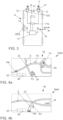
- a navigation map KAH with a stay history can be seen.
- This shows the current position PK of the motor vehicle K on roads S.
- the motor vehicle K moves towards a road intersection 23. Buildings are indicated at 24.
- pedestrians Fx are shown, which are at certain positions on the navigation map KAH (according to experience) at the time the motor vehicle K is traveling due to the transmitted location history AH.
- Fig. 4b shows a map display as shown in Fig. 4b.
- This figure shows a current navigation map Cactus, in which currently detected cyclists/pedestrians can be seen. These are therefore concrete and promptly in accordance with the method variant presented at the beginning ( Fig. 1 ) recorded. It can be seen that only one cyclist R1 was detected. The lighting device of the motor vehicle K can be controlled accordingly in order not to blind the cyclist R1 but still to illuminate him.
- the type of control of the lighting device 12 from the motor vehicle K changes automatically depending on the navigation map (KAH or Kakt) selected by the vehicle driver.
- the navigation map KAH is displayed, the lighting device 12 is activated across the board based on the empirical values.
- the lighting device 12 is activated based on timely received position data of moving objects that are actually present in the area of the motor vehicle K.
- the display device 16 is controlled depending on pedestrians or cyclists actually detected in such a way that, starting from any display on the display device 16, a representation according to Fig. 4b is changed. This can also be combined with an acoustic or visual warning signal.
- the position data collected and stored in an order history can be used to control a high beam in such a way that the high beam only shines up to a certain maximum height in areas with a statistically high number of pedestrians and/or cyclists.
- a normal high beam distribution FL is indicated by dashed lines, as can be generated or is generated under normal conditions with little risk of glare (e.g. on country roads).
- FL' denotes such a high beam distribution that can be generated or is generated in areas with a statistically high number of pedestrians Fx or cyclists Rx. It can be seen that the high beam distribution FL has a maximum height HFLmax, which is clearly above the heads of the cyclists Rx or Fx and can therefore blind them.
- a height HFL of the high beam distribution FL' lies below the heads of the cyclists Rx or pedestrians Fx. The risk of glare can thus be avoided.
- the Fig. 6 shows an embodiment of the method in which a pedestrian F2 is in turn equipped with a GPS device 20 in the form of a smartphone.
- global position data of the pedestrian F2 can be recorded promptly via GPS signals and transmitted to the remote computer unit 10 via the Internet connection I20 of the smartphone.
- the global position data of the pedestrian F2 can be made available to the motor vehicle K again via an Internet connection IK.
- the motor vehicle K then controls its lighting device 12 in such a way that, with a high beam distribution FL, a light-free high beam corridor FLK is generated for the pedestrian F2.
- the high beam distribution FL is thus hidden in the area of the pedestrian F2.
- Fig. 7 shows how a city light distribution SL can be varied depending on the number of pedestrians present.
- the pedestrians Fx in turn carry smartphones (not shown) with them so that their global positions can be recorded and these can be transmitted to a computer unit 10 via an Internet connection IFX.
- the global position data of the pedestrians Fx can in turn be made available to the motor vehicle K by the computer unit 10 via an Internet connection IK. Since the position data indicates to the motor vehicle K that the pedestrians Fx are on the right side of the road, the city light distribution SL is directed to the right side of the road.
- a pedestrian F in turn carries a smartphone, not shown, and both global position and movement data of the pedestrian F are transmitted to the remote computer unit 10 via an Internet connection IF.
- the reference symbols F' and F" indicate positions of the pedestrian F that he had recently occupied.
- the position or movement data of the pedestrian F are in turn made available to the motor vehicle K via an Internet connection IK.
- the computer unit 11 estimates from this data using a suitable logic determines a movement trajectory TF of the pedestrian, which in the present case runs over a pedestrian crossing Z.
- the computer unit 11 knows a movement trajectory TK of the motor vehicle K. From this it can be calculated whether an intersection SP occurs between the movement trajectories TF and TK and There is therefore a risk of collision.
- the lighting device 12, the acoustic device 27 designed as a signal horn (see Fig. 3 ) and the display device 16 are controlled in such a way that a visual and/or acoustic warning is sent to both the pedestrian F and the driver of the motor vehicle K.
- the warning can also be given as text and/or voice output.
- an additional acoustic device e.g. loudspeaker located in the interior of the motor vehicle K is controlled in such a way that an acoustic warning is (also) issued via this device.
Landscapes
- Physics & Mathematics (AREA)
- General Physics & Mathematics (AREA)
- Chemical & Material Sciences (AREA)
- Analytical Chemistry (AREA)
- Engineering & Computer Science (AREA)
- Mechanical Engineering (AREA)
- Human Computer Interaction (AREA)
- Acoustics & Sound (AREA)
- Lighting Device Outwards From Vehicle And Optical Signal (AREA)
Description
- Die Erfindung betrifft ein Verfahren zur Ansteuerung wenigstens einer Vorrichtung von einem Kraftfahrzeug mit den Merkmalen vom Oberbegriff des Patentanspruchs 1.
- Ein Verfahren zum Steuern eines Scheinwerfers eines Fahrzeugs wird in der
EP 3 112 214 A1 beschrieben. Konkret ist dort ein Verfahren zum Steuern eines Scheinwerfers eines Fahrzeugs offenbart, bei dem zunächst ein durch ein Objekt (bspw. entgegenkommendes Fahrzeug) bereitgestelltes und eine Position des Objekts repräsentierendes Fahrzeugpositionssignal eingelesen wird. Daraufhin werden die Position des Fahrzeugs und die Position des Objekts unter Verwendung des Objektpositionssignals und des Fahrzeugpositionssignals miteinander verglichen, um eine relative Position des Fahrzeugs zum Objekt zu ermitteln. In Abhängigkeit von der relativen Position des Fahrzeugs zum Objekt wird dann ein Steuersignal zum Steuern des Scheinwerfers erzeugt. Das Steuersignal dient dazu, um den Scheinwerfer abzublenden, um einen Scheinwerferstrahl vom Objekt wegzulenken oder einen solchen auf das Objekt hinzulenken. Der Schritt des Einlesens, des Vergleichens und des Erzeugens des Steuersignals wird durch eine von dem Fahrzeug getrennte Datenverarbeitungseinheit durchgeführt. Bei dem Objekt kann es sich auch um eine Person handeln, die ein Mobiltelefon mit sich trägt, mit dem Objektpositionssignale generiert und versendet werden können. - Ein Verfahren zur Fahrzeug-Fußgänger-Kommunikation ist aus der
DE 10 2014 110 958 A1 bekannt geworden. Konkret wird in diesem Dokument ein Fahrzeug-Fußgänger-Kommunikationssystem beschrieben. Das System dient zur Warnung von jeweils ein Gerät des Systems nutzenden Bedienern. Dabei wird ein erstes Gerät durch einen Fußgänger mitgeführt und bedient. Ein zweites Gerät ist in einem Kraftfahrzeug installiert und durch einen Fahrer bedienbar. Das System ist dazu ausgebildet, über das erste Gerät und/oder das zweite Gerät eine Warnung an den Fahrer und/oder den Fußgänger auszugeben. Insbesondere wird eine Warnung ausgegeben, wenn auf Grund von erfassten Parametern, wie globaler Position und/oder Geschwindigkeit festgestellt wurde, dass sich der voraussichtliche Weg des Fahrzeugs und der voraussichtliche Weg des Fußgängers schneiden. Unter anderem wird beschrieben, dass die Scheinwerfer auf einen erkannten Fußgänger gerichtet werden können. Es wird auch erwähnt, die Scheinwerfer aufzublenden und zu hupen, wenn eine Ablenkung des Fußgängers erkannt wird. Ebenso können über eine Mensch-Maschine-Schnittstelle (HMI) optische und/oder akustische Warnungen an den Fahrer ausgegeben werden. - In der
DE 10 2010 048 470 A1 wird ebenfalls ein Fahrzeug-Fußgänger-Kommunikationssystem offenbart. Dabei ist eine fahrzeugbasierte Vorrichtung zum Empfangen und Übertragen der globalen Positionierung des Fahrzeugs und eine fußgängerbasierte Vorrichtung zum Empfangen und Übertragen einer globalen Position des Fußgängers vorhanden. Dem Fahrzeug und/oder dem Fußgänger wird ein Alarmsignal geliefert, welches basierend auf den jeweiligen globalen Positionsdaten dem einen Verkehrsteilnehmer jeweils eine Gegenwart des anderen Verkehrsteilnehmers angibt. Es wird auch vorgeschlagen, bei Erfassung eines Fußgängers schwenkbare Scheinwerfer des Kraftfahrzeugs in horizontaler und/oder vertikaler Richtung zu bewegen, um den Fußgänger anzuvisieren und anzustrahlen. - Den oben genannten Systemen ist gemeinsam, dass diese eine zwischen dem Fußgänger und dem Kraftfahrzeug abgestimmte, spezielle Kommunikationseinrichtung erforderlich machen. Dies ist mit zusätzlichen Kosten und einer erforderlichen Verbreitung der speziellen Kommunikationseinrichtungen im Feld verbunden, was eine allgemeine Praktikabilität der Vorschläge infrage stellt.
- Aus dem allgemeinen Stand der Technik ist es auch bekannt, Scheinwerfer als Markierungslicht zum Fußgängerschutz einzusetzen. Hierbei wird mit einer Kamera ein Fußgänger erkannt und über einen Lichtspot markiert bzw. angestrahlt. Problematisch sind hierbei allerdings häufig auftretende Kameraprobleme (z.B. Erkennungsreichweite, Probleme bei Verdeckung und Witterung).
- Schließlich ist der die Merkmale vom Oberbegriff des Patentanspruchs 1 bildenden
WO 2016/070193 A1 ein Verfahren zu entnehmen, bei dem Informationen über Verkehrsteilnehmer (Fußgänger, Radfahrer, Kraftfahrzeuge) gesammelt, ausgewertet und anderen Verkehrsteilnehmern zur Verfügung gestellt werden. Konkret werden über mobile Endgeräte der Verkehrsteilnehmer deren Orts- und Bewegungsdaten gesammelt. Die gesammelten Daten der Verkehrsteilnehmer werden dahingehend ausgewertet, ob eine Wahrscheinlichkeit einer Kollision gegeben ist. Liegt die ermittelte Wahrscheinlichkeit über einem bestimmten Grenzwert, so wird eine Warnmeldung an die mobilen Endgeräte der betroffenen Verkehrsteilnehmer ausgegeben. - Ausgehend vom Stand der Technik liegt der vorliegenden Erfindung somit die Aufgabe zu Grunde, ein Verfahren zur Ansteuerung wenigstens einer Vorrichtung von einem Kraftfahrzeug zur Verfügung zu stellen, durch welches Verkehrssicherheit für Verkehrsteilnehmer erhöht werden kann.
- Vorliegende Aufgabe wird mit den Merkmalen von Patentanspruch 1 gelöst. Vorteilhafte Ausführungen beziehungsweise Weiterbildungen der Erfindung sind den abhängigen Ansprüchen zu entnehmen.
- Die Erfindung geht aus von einem Verfahren zur Ansteuerung wenigstens zweier Vorrichtungen von einem Kraftfahrzeug, bei dem die wenigstens zwei Vorrichtungen zumindest in Abhängigkeit von erfassten globalen Positionsdaten wenigstens eines Fußgängers und/oder wenigstens eines Radfahrers angesteuert wird. Die globalen Positionsdaten sind vorzugsweise Daten eines GPS-Systems (GPS = Globales Positionsbestimmungssystem).
- Es wird ferner vorgeschlagen, dass die Positionsdaten des wenigstens einen Fußgängers und/oder des wenigstens einen Radfahrers erfasst, an eine entfernt liegende (zentrale) Computereinheit übermittelt und einer Computereinheit des Kraftfahrzeugs zur Verfügung gestellt werden.
- Es erfolgt also bei dem Verfahren keine direkte Kommunikation zwischen einem vom Fußgänger oder Radfahrer genutzten Gerät und dem Kraftfahrzeug, sondern erfasste globale Positionsdaten werden zunächst in einer entfernt liegenden Computereinheit (sogenannter Cloudrechner) "zwischengelagert", und aufbereitet bevor sie von einer Computereinheit eines Kraftfahrzeugs abgegriffen beziehungsweise dieser zur Verfügung gestellt werden.
- Das Verfahren nutzt somit allgemein zur Verfügung stehende Techniken des Internets und macht eine spezielle Ausrüstung, insbesondere eine Ausrüstung, welche eine Fahrzeug-Fußgänger-Kommunikation ermöglicht, entbehrlich.
- Die Erfassung der globalen Positionsdaten eines Fußgängers und/oder eines Radfahrers kann beispielsweise über ein gewöhnliches Internet- und GPS-fähiges Smartphone erfolgen. Es ist aber auch denkbar, dass globale Positionsdaten nicht von Geräten erfasst werden, welche von einem Fußgänger oder Radfahrer mitgeführt werden. Es ist auch eine Erfassung von globalen Positionsdaten eines Fußgängers oder Radfahrers durch Geräte denkbar, welche getrennt von solchen Personen stationär installiert sind. Denkbar ist beispielsweise die Erfassung von Positionsdaten durch geeignete Kameras an Straßenkreuzungen. Derartige Kameras können bei Erkennung von Personen eine signaltechnisch verbundene GPS-Einheit ansteuern, welche ihrerseits ein GPS-Signal der Kameraposition an die entfernt liegende Computereinheit übermittelt.
- Gemäß einem Merkmal der Erfindung ist eine der Vorrichtungen eine Anzeigevorrichtung. Gemäß einem Merkmal des erfindungsgemäßen Verfahrens ist eine der Vorrichtungen eine Beleuchtungsvorrichtung. Somit wird auf einfache Weise eine Ansteuerung von Vorrichtungen des Kraftfahrzeugs ermöglicht, die einen Fahrer auf das Vorhandensein von Gefahren hinweisen bzw. mögliche Kollisionsobjekte sichtbar machen können.
- Es werden in der entfernt liegenden Computereinheit Positionsdaten von einer Vielzahl von Fußgängern und/oder Radfahrern über einen bestimmten Zeitraum gesammelt. Der Zeitraum kann beispielsweise ein Tag betragen. Es ist auch denkbar, den Zeitraum über ein ganzes Jahr oder länger zu erstrecken. Aus den gesammelten Daten kann dann eine orts- und zeitabhängige Aufenthaltshistorie (Aufenthaltswahrscheinlichkeit) von Fußgängern und/oder Radfahrern gebildet werden.
- Der große Vorteil liegt darin, dass man nicht unbedingt auf die Erfassung und Weiterleitung von Positionsdaten eines konkreten Fußgängers oder Radfahrers in Echtzeit angewiesen ist. Vielmehr können die gesammelten Daten nach einem Download durch die Computereinheit des Kraftfahrzeugs dazu genutzt werden, um die wenigstens eine Vorrichtung vom Kraftfahrzeug zumindest mit einer statistisch hohen Wahrscheinlichkeit auch ohne Echtzeiterfassung bedarfsgerecht ansteuern zu können.
- So ist gemäß einer Weiterbildung der Erfindung beispielsweise denkbar, dass die gesammelten Positionsdaten zur Ansteuerung eines von einer Beleuchtungsvorrichtung des Kraftfahrzeugs erzeugten Stadtlichtes in der Art genutzt werden, dass das Stadtlicht im Bereich mit statistisch hohem Aufkommen an Fußgängern und/oder Radfahrern eingeschaltet wird. Somit können beispielsweise Geh- und/oder Radwege an bestimmten Orten und zu bestimmten Zeiten durch ein eingeschaltetes Stadtlicht extra beleuchtet werden, um Radfahrer oder Fußgänger früher sichtbar zu machen.
- Eine andere Ausbildung des Erfindungsgedankens schlägt vor, dass die gesammelten Positionsdaten zur Ansteuerung eines von einer Beleuchtungsvorrichtung des Kraftfahrzeugs erzeugten Fernlichts in der Art genutzt werden, dass eine Fernlichtverteilung in Bereichen mit statistisch hohem Aufkommen an Fußgängern und/oder Radfahrern nur bis zu einer solchen Höhe reicht, die unter einer vom Fernlicht maximal erreichbaren Höhe einer gewöhnlich erzeugbaren Fernlichtverteilung liegt. Hierdurch kann eine mögliche Blendung dieser Verkehrsteilnehmer zum einen wirksam verhindert werden, zum anderen dennoch deren Erkennbarkeit verbessert werden.
- Wenn Positions- und Richtungsdaten eines Fußgängers und/oder eines Radfahrers in Echtzeit erfasst und weitergeleitet werden, so erscheint es zweckmäßig, wenn diese Daten vom Kraftfahrzeug dazu genutzt werden, um eine Stadtlichtverteilung auf diejenige Seite einer Fahrbahn zu richten, auf der sich der Fußgänger oder der Radfahrer auch tatsächlich befindet.
- Unter Stadtlicht wird eine derartige Einrichtung moderner Scheinwerfer verstanden, bei der durch eine Verbreiterung und Symmetrieerhöhung des Lichtkegels eine bessere Ausleuchtung von Fuß- beziehungsweise Radwegen erreicht werden kann.
- Allerdings kann auch die Situation auftreten, in der bekannt ist, dass die Positionsdaten nur mit einer großen Ungenauigkeit erfasst werden beziehungsweise erfasst werden können. Dies kann beispielsweise anhand eines schlechten oder schwachen GPS-Signals abgeschätzt werden. In einem solchen Fall ist es dann sehr zweckmäßig, wenn das Stadtlicht auf beide Seiten der Fahrbahn gerichtet wird. Ungenaue Positionsdaten können somit zumindest zu einem Teil ausgeglichen werden.
- Im Stand der Technik bekannte Lichtassistenten nutzen eine Kamera, um anhand von erkannten Frontscheinwerfern beziehungsweise Heckleuchten anderer Fahrzeuge eingeschaltetes Fernlicht abzublenden und somit eine Blendung der anderen Verkehrsteilnehmer zu vermeiden. Eine solche Vorgehensweise ist bei Fußgängern nicht und bei Radfahrern nur sehr eingeschränkt möglich, da Fußgänger bei Dunkelheit schlecht erkannt werden und die Beleuchtung bei Radfahrern nicht so hell ist wie bei Kraftfahrzeugen. Daher ist es gemäß einer anderen Weiterbildung der Erfindung denkbar, dass die Positionsdaten des wenigstens einen Fußgängers und/oder des wenigstens einen Radfahrers vom Kraftfahrzeug dazu genutzt werden, um eine Fernlichtverteilung vom Fußgänger oder Radfahrer auszublenden.
- Um die Qualität der Positionsdaten zu verbessern wird gemäß einer anderen Ausbildung der Erfindung vorgeschlagen, die Positionsdaten über eine Navigationskarte abzugleichen. Bewegt sich beispielsweise ein Objekt in Nähe des Kraftfahrzeugs und auch in gleicher Bewegungsrichtung und werden Positionsdaten außerhalb eines bekannten, rechtsseitigen Geh- oder Fahrradweges angezeigt, so ist eine Korrektur der Position des Objektes auf den Geh- oder Fahrradweg mit großer Wahrscheinlichkeit angebracht.
- Ein solcher Abgleich, welcher auch Map-Matching genannt wird, kann durch die zentrale Computereinheit oder auch durch die lokale Computereinheit im Kraftfahrzeug erfolgen.
- Gemäß einer anderen Weiterbildung wird schließlich auch noch vorgeschlagen, dass zusätzlich zu den absoluten Positionsdaten auch relative Bewegungsdaten erfasst werden und mit deren Hilfe eine zu erwartende Bewegungstrajektorie des wenigstens einen Fußgängers und/oder des wenigstens einen Radfahrers abgeschätzt wird. Falls sich die Bewegungstrajektorie des Kraftfahrzeugs und diejenige des Fußgängers oder Radfahrers kreuzen, so kann dann eine optische und/oder akustische Warnung durch das Kraftfahrzeug an den Fahrzeugführer und/oder den Fußgänger oder Radfahrer abgegeben werden.
- Schließlich soll auch ein Kraftfahrzeug beschrieben werden, mit dem das erfindungsgemäße Verfahren durchführbar ist. Ein derartig hergerichtetes Kraftfahrzeug weist wenigstens eine Beleuchtungsvorrichtung und/oder wenigstens eine Anzeigevorrichtung sowie wenigstens eine im Kraftfahrzeug fest installierte, lokale Computereinheit auf. Ferner ist eine Internetschnittstelle zur Kommunikation der lokalen Computereinheit mit wenigstens einer entfernt liegenden Computereinheit (Cloudrechner) vorhanden. Durch die lokale Computereinheit sind globale Positionsdaten wenigstens eines Fußgängers und/oder wenigstens eines Radfahrers von der entfernt liegenden Computereinheit herunterladbar oder diese werden heruntergeladen. Ferner ist die lokale Computereinheit mit wenigstens einer Steuereinheit zur Ansteuerung der wenigstens einen Beleuchtungsvorrichtung und/oder der wenigstens einen Anzeigevorrichtung vom Kraftfahrzeug verbunden. Dies erfolgt derart, dass die Beleuchtungseinrichtung in Abhängigkeit von heruntergeladenen, globalen Positionsdaten wenigstens eines Fußgängers und/oder wenigstens eines Radfahrers ansteuerbar ist oder angesteuert wird.
- Bevorzugte Ausführungsbeispiele der Erfindung sind in den Figuren dargestellt und werden anhand der Figuren in der nachfolgenden Beschreibung näher erläutert. Dadurch werden auch noch weitere Vorteile der Erfindung deutlich. Gleiche Bezugszeichen, auch in unterschiedlichen Figuren, beziehen sich auf gleiche, vergleichbare oder funktional gleiche Bauteile. Dabei werden entsprechende oder vergleichbare Eigenschaften und Vorteile erreicht, auch wenn eine wiederholte Beschreibung oder Bezugnahme darauf nicht erfolgt. Die Figuren sind nicht immer maßstabsgetreu. In manchen Figuren können Proportionen übertrieben dargestellt sein, um Merkmale eines Ausführungsbeispiels deutlicher hervorheben zu können.
-
- Fig. 1
- die Darstellung des Verfahrens in einer ersten Ausführungsform,
- Fig. 2
- die Darstellung des Verfahrens in einer zweiten Ausführungsform,
- Fig. 3
- die Darstellung eines Kraftfahrzeugs zur Durchführung des Verfahrens,
- Fig. 4
- die Darstellung einer Navigationskarte in verschiedenen Modi des Verfahrens,
- Fig. 5
- die Darstellung einer Fernlichtverteilung, bei örtlich und zeitlich statistisch hoher Dichte an Fußgängern und/oder Radfahrern,
- Fig. 6
- die Darstellung eines maskierten Fernlichts in Zusammenhang mit dem Verfahren,
- Fig. 7
- die Darstellung zweiter unterschiedlicher Stadtlichtverteilungen in Abhängigkeit von der Qualität empfangener GPS-Signale und
- Fig. 8
- die Ausgabe von Warnungen an den Fahrer und/oder den Fußgänger bei Überschneidung der Bewegungstrajektorien vom Kraftfahrzeug und Fußgänger.
- Zunächst wird auf die
Fig. 1 Bezug genommen. Auf dieser Figur ist ein Kraftfahrzeug K ersichtlich, welches sich auf einer Fahrbahn 13 in einer Fahrtrichtung (vgl. Pfeil) bewegt. Rechts neben der Fahrbahn 13 sind ein Fußweg 17 und ein Radweg 18 vorhanden. - Auf dem Fußweg 17 laufen Fußgänger F1 bis F3 und auf dem Fahrradweg 18 sind zwei Radfahrer R1 und R2 unterwegs. Die Pfeile zeigen jeweils die Bewegungs- beziehungsweise Fahrtrichtung an.
- Das Kraftfahrzeug K weist eine lokale Computereinheit 11 auf sowie eine Internetschnittstelle 15 und eine GPS-Einrichtung 14. Über die Internetschnittstelle 15 ist das Kraftfahrzeug K in der Lage, eine Internetverbindung IK mit einer entfernt befindlichen Computereinheit 10 (Cloudrechner) aufzubauen. Über die GPS-Einrichtung 14 kann das Kraftfahrzeug K GPS-Signale GPS mit mehreren Satelliten SAT (nur einer ist dargestellt) austauschen.
- Einer der Fußgänger, nämlich der Fußgänger F2 führt eine GPS-Einrichtung 20 in Form eines handelsüblichen Smartphones mit sich. Ebenso trägt der Radfahrer R1 eine GPS-Einrichtung 19 in Form eines handelsüblichen Smartphones bei sich.
- So sind der Fußgänger F2 und der Radfahrer R1 in der Lage, GPS-Signale GPS mit Satelliten SAT auszutauschen und mit der entfernt befindlichen Computereinheit 10 Internetverbindungen I20 beziehungsweise 119 aufzubauen.
- Über die Internetverbindungen I19 und I20 senden der Radfahrer R1 und der Fußgänger F2 ständig ihre erfassten, globalen Positionsdaten an die entfernt befindliche Computereinheit 10.
- Die Internetverbindung IK dient dazu, dass die erfassten Positionsdaten von der Computereinheit 10 an die lokale Computereinheit 11 des Kraftfahrzeugs K übermittelt und dem Kraftfahrzeug K so zur Verfügung gestellt werden können.
- Die Computereinheit 11 wertet die Positionsdaten aus und nutzt diese, um damit eine Beleuchtungsvorrichtung 12 in Form von Scheinwerfern bedarfs- und situationsgerecht anzusteuern.
- Im konkreten Fall wird die Beleuchtungsvorrichtung 12 derart angesteuert, dass eine Stadtlichtverteilung SL auf diejenige Seite der Fahrbahn 13 gerichtet wird, wo sich tatsächlich Fußgänger und/oder Radfahrer befinden.
- Die Stadtlichtverteilung SL wird also in Richtung des Fußwegs 17 und des Radwegs 18 gerichtet und beleuchtet somit die dort befindlichen Fußgänger und Radfahrer.
- Es findet also keine direkte Kommunikation zwischen dem Fußgänger F2 und dem Kraftfahrzeug K oder dem Radfahrer R1 und dem Kraftfahrzeug K statt. Die Kommunikation der Positionsdaten vom Fußgänger F2 beziehungsweise vom Radfahrer R1 läuft somit ausschließlich über die entfernt befindliche Computereinheit 10.
- Das Verfahren hat also den Vorteil, dass weder das Kraftfahrzeug K noch der Fußgänger F2, noch der Radfahrer R1 eine spezielle Ausrüstung benötigen, damit deren globale Positionsdaten dem Kraftfahrzeug K zur Verfügung gestellt und das Kraftfahrzeug K seine Beleuchtungsvorrichtung 12 entsprechend ansteuern kann.
- Anhand von
Fig. 2 wird nun eine Variante des Verfahrens dargestellt. Im Unterschied zur ersten Variante werden hierbei in der entfernt liegenden Computereinheit 10 von einer Vielzahl von Fußgängern und/oder Radfahrern globale Positionsdaten über einen bestimmten oder zu bestimmenden Zeitraum gesammelt. Aus diesen Daten wird eine orts-und zeitabhängige Aufenthaltshistorie (Aufenthaltswahrscheinlichkeit) errechnet. - So ist eine Straßenkreuzung 21 zu verschiedenen, sich über ein Jahr erstreckenden Zeitpunkten ersichtlich. Im Bereich der Straßenkreuzung 21 sind Kamerasysteme 22 fest installiert, welche eine GPS-Einrichtung aufweisen und mit einer Internetschnittstelle verbunden sind (nicht näher dargestellt).
- Über die GPS-Einrichtung können die Kamerasysteme 22 GPS-Daten GPS mit Satelliten SAT austauschen. Über die Internetschnittstelle kann eine Internetverbindung I22 zwischen den Kamerasystemen 22 und der Computereinheit 10 aufgebaut werden.
- Werden zu einem bestimmten Zeitpunkt über die Kamerasysteme 22 Fußgänger Fx im Bereich der Straßenkreuzung 21 erfasst, so wird die Anzahl A der erfassten Fußgänger Fx zusammen mit dem Datum D, der Uhrzeit U sowie den globalen Positionsdaten GP der Kamerasysteme 22 und damit in etwa der Straßenkreuzung 21 an die Computereinheit 10 übermittelt. Diese legt in einem geeigneten Speicher diese Daten ab und bildet eine Aufenthaltshistorie AH für den unmittelbaren Umgebungsbereich der Straßenkreuzung 21 ab.
- Entsprechend kann an beliebigen anderen Orten beziehungsweise Bereichen verfahren werden. Der Vorteil liegt darin, dass Fußgänger und/oder Fahrradfahrer, welche sich in einem solchen erfassten Bereich wie die Straßenkreuzung 21 befinden, keinerlei zusätzliche Spezialausrüstung benötigen, nicht einmal ein handelsübliches Smartphone.
- So wird in der Aufenthaltshistorie AH beispielsweise niedergelegt, dass sich am 01.01.XX, um 9.00 Uhr im Bereich der Straßenkreuzung 21 sieben Fußgänger Fx befanden. Am 06.04.XX, um 3.00 Uhr wurde nur ein Fußgänger erfasst. Dafür hielten sich am 21.07.XX, um 21.15 Uhr im Bereich der Straßenkreuzung 21 achtundzwanzig Fußgänger Fx auf. Am 31.12.XX, um 19.00 Uhr waren es lediglich vier.
- Die Aufenthaltshistorie AH kann von der Computereinheit 10 über eine Internetverbindung IK dem Kraftfahrzeug K zur Verfügung gestellt werden. Das Kraftfahrzeug K kann diese Daten dann dazu nutzen, um auf einer geeigneten, kraftfahrzeugeigenen Anzeigeeinheit bei Bedarf eine Kartendarstellung anzuzeigen, in der zeitbezogene Aufenthalts-Wahrscheinlichkeiten von Fußgängern und/oder Radfahrern dargestellt sind (wird an anderer Stelle noch gezeigt).
- Anhand der
Fig. 3 soll nun noch einmal etwas detaillierter das zum erfindungsgemäßen Verfahren hergerichtete Kraftfahrzeug K dargestellt werden. - So ist die lokale Computereinheit 11 signaltechnisch mit der GPS-Einrichtung 14 und mit der Internetschnittstelle 15 verbunden. Über die Internetschnittstelle 15 kann die Internetverbindung IK des Kraftfahrzeugs K zur entfernt befindlichen Computereinheit 10 aufgebaut werden. Die erfassten und der Computereinheit 11 zur Verfügung stehenden Daten werden genutzt, um in einer Steuereinheit 11a entsprechende Steuersignale zur Ansteuerung der Beleuchtungsvorrichtung 12 zu generieren. Die Beleuchtungsvorrichtung 12 besteht aus zwei Scheinwerfern, welche über Schwenkpunkte 120 sowohl in einer Horizontalrichtung H als auch in einer Vertikalrichtung V schwenkbar sind.
- Eine Anzeigevorrichtung 16, welche beispielsweise als Display oder bedienbarer Touchscreen ausgebildet sein kann, erlaubt es einem Fahrer, sich bei Bedarf eine Navigationskarte anzeigen zu lassen, die beispielsweise für das von ihm gerade befahrene Gebiet eine Aufenthaltshistorie beziehungsweise eine Aufenthaltswahrscheinlichkeit von Fußgängern und/oder Radfahrern anzeigt. Ferner ist eine akustische Vorrichtung 27 in Form eines Signalhorns vorhanden.
- Die genannten Vorrichtungen 12, 16 und 27 sowie die Computereinheit 11, die Steuereinheit 11a und die GPS-Einrichtung 14 sind fest im Kraftfahrzeug K installiert, also Bestandteile des Kraftfahrzeugs K.
- So ist anhand der
Fig. 4a eine Navigationskarte KAH mit einer Aufenthaltshistorie ersichtlich. Darin wird die aktuelle Position PK des Kraftfahrzeugs K auf Straßen S dargestellt. Das Kraftfahrzeug K bewegt sich auf eine Straßenkreuzung 23 zu. Mit 24 sind Gebäude angedeutet. Des Weiteren sind Fußgänger Fx dargestellt, welche sich zur Fahrzeit des Kraftfahrzeugs K auf Grund der übermittelten Aufenthaltshistorie AH an bestimmten Positionen auf der Navigationskarte KAH (erfahrungsgemäß) befinden. - Mit 25 und 26 werden dem Fahrer Softkeys zur Verfügung gestellt, mit deren Hilfe er auf ein nicht dargestelltes Hauptmenü zurückspringen oder in eine solche Kartendarstellung wechseln kann, wie sie in
Fig. 4b dargestellt ist. In dieser Figur ist eine aktuelle Navigationskarte Kakt dargestellt, in welcher aktuell erfasste Radfahrer/Fußgänger ersichtlich sind. Diese werden also konkret und zeitnah gemäß der anfangs dargestellten Verfahrensvariante (Fig. 1 ) erfasst. Es ist ersichtlich, dass hierbei lediglich ein Radfahrer R1 erfasst wurde. Die Beleuchtungseinrichtung des Kraftfahrzeugs K kann entsprechend angesteuert werden, um den Radfahrer R1 nicht zu blenden und dennoch zu beleuchten. - Die Art der Ansteuerung der Beleuchtungsvorrichtung 12 vom Kraftfahrzeug K wechselt automatisch in Abhängigkeit der vom Fahrzeugführer gewählten Navigationskarte (KAH oder Kakt). So wird bei Anzeige der Navigationskarte KAH die Beleuchtungsvorrichtung 12 auf Basis der Erfahrungswerte pauschal angesteuert. Bei Wahl der Navigationskarte Kakt hingegen erfolgt eine Ansteuerung der Beleuchtungsvorrichtung 12 auf Grund von zeitnah empfangenen Positionsdaten von bewegten Objekten, die tatsächlich im Bereich des Kraftfahrzeugs K vorhanden sind. Es ist auch denkbar, dass die Anzeigevorrichtung 16 in Abhängigkeit von tatsächlich erfassten Fußgängern oder Radfahrern derart angesteuert wird, dass ausgehend von einer beliebigen Anzeige auf der Anzeigevorrichtung 16 in eine Darstellung gemäß
Fig. 4b gewechselt wird. Dies kann zusätzlich mit einem akustischen oder optischen Warnsignal verbunden sein. - Wie bereits erwähnt, ist denkbar, dass die gesammelten und in einer Auftragshistorie abgelegten Positionsdaten zur Ansteuerung eines Fernlichts in der Art genutzt werden können, dass das Fernlicht in Bereichen mit statistisch hohem Aufkommen an Fußgängern und/oder Radfahrern nur bis zu einer bestimmten Maximalhöhe strahlt.
- Dies ist in
Fig. 5 dargestellt. Hierbei ist eine gewöhnliche Fernlichtverteilung FL gestrichelt angedeutet, wie sie unter normalen Bedingungen mit wenig Blendungsgefahr (z.B. auf Landstraßen) erzeugbar ist oder erzeugt wird. Mit FL' ist eine solche Fernlichtverteilung beziffert, wie sie in Gebieten mit statistisch hohem Aufkommen an Fußgängern Fx oder Radfahrern Rx erzeugbar ist oder erzeugt wird. Es ist ersichtlich, dass die Fernlichtverteilung FL eine Maximalhöhe HFLmax aufweist, welche deutlich über den Köpfen der Radfahrer Rx beziehungsweise Fx liegt, diese also blenden kann. Eine Höhe HFL der Fernlichtverteilung FL' hingegen liegt unterhalb der Köpfe der Radfahrer Rx beziehungsweise Fußgänger Fx. Die Gefahr einer Blendung kann somit vermieden werden. - Die
Fig. 6 zeigt eine Ausbildung des Verfahrens, bei dem ein Fußgänger F2 wiederum mit einer GPS-Einrichtung 20 in Form eines Smartphones ausgestattet ist. Hierdurch können zeitnah über GPS-Signale GPS globale Positionsdaten des Fußgängers F2 erfasst und über die Internetverbindung I20 des Smartphones an die entfernt liegende Computereinheit 10 übermittelt werden. Über eine Internetverbindung IK können die globalen Positionsdaten des Fußgängers F2 dem Kraftfahrzeug K wieder zur Verfügung gestellt werden. Das Kraftfahrzeug K steuert daraufhin seine Beleuchtungsvorrichtung 12 derart an, dass bei einer Fernlichtverteilung FL ein lichtfreier Fernlichtkorridor FLK für den Fußgänger F2 erzeugt wird. Die Fernlichtverteilung FL wird somit im Bereich des Fußgängers F2 ausgeblendet. - Anhand der
Fig. 7 ist dargestellt, wie auch eine Stadtlichtverteilung SL in Abhängigkeit von konkret vorhandenen Fußgängern variiert werden kann. So führen die Fußgänger Fx wiederum nicht näher dargestellte Smartphones mit sich, so dass deren globale Positionen erfasst und diese über eine Internetverbindung IFX einer Computereinheit 10 übermittelt werden können. Die globalen Positionsdaten der Fußgänger Fx können wiederum über eine Internetverbindung IK von der Computereinheit 10 dem Kraftfahrzeug K zur Verfügung gestellt werden. Da die Positionsdaten dem Kraftfahrzeug K anzeigen, dass sich die Fußgänger Fx auf der rechten Seite der Fahrbahn befinden, wird die Stadtlichtverteilung SL auf die rechte Seite der Fahrbahn gerichtet. - Allerdings kann es auch vorkommen, dass erkannt wird, dass die gelieferten Positionsdaten der Fußgänger Fx eine schlechte Qualität aufweisen. Dies soll mit Fx' angedeutet werden. In einem solchen Fall ist es zweckmäßig, wenn eine solche Stadtlichtverteilung SL' erzeugt wird, welche auf beide Seiten der Fahrbahn gerichtet ist. Somit kann man sichergehen, dass die Fußgänger Fx im Bereich des Kraftfahrzeugs K trotz schlechter Qualität der GPS-Signale GPS mit hoher Wahrscheinlichkeit beleuchtet werden.
- Schließlich wird anhand von
Fig. 8 ein Aspekt des Verfahrens dargestellt, bei dem ein Fußgänger F wiederum ein nicht näher dargestelltes Smartphone mit sich führt und über eine Internetverbindung IF sowohl globale Positions- als auch Bewegungsdaten des Fußgängers F an die entfernt liegende Computereinheit 10 übermittelt werden. Mit den Bezugszeichen F' und F" sind Positionen des Fußgängers F angedeutet, die er kurz zuvor innehatte. Die Positions- beziehungsweise Bewegungsdaten des Fußgängers F werden dem Kraftfahrzeug K wiederum über eine Internetverbindung IK zur Verfügung gestellt. Aus diesen Daten schätzt die Computereinheit 11 mittels einer geeigneten Logik eine Bewegungstrajektorie TF des Fußgängers ab, welche im vorliegenden Fall über einen Fußgängerüberweg Z verläuft. Gleichermaßen ist der Computereinheit 11 eine Bewegungstrajektorie TK des Kraftfahrzeugs K bekannt. Hieraus kann berechnet werden, ob ein Schnittpunkt SP zwischen den Bewegungstrajektorien TF und TK auftritt und somit eine Kollisionsgefahr gegeben ist. - In einem solchen Fall können über die Computereinheit 11 die Beleuchtungsvorrichtung 12, die als Signalhorn ausgebildete, akustische Vorrichtung 27 (vergleiche
Fig. 3 ) und die Anzeigevorrichtung 16 derart angesteuert werden, dass eine optische und/oder akustische Warnung sowohl an den Fußgänger F als auch an den Fahrer des Kraftfahrzeugs K ergeht. Die Warnung kann auch als Text- und/oder Sprachausgabe abgegeben werden. Es ist auch denkbar, dass eine zusätzlich im Innenraum des Kraftfahrzeugs K befindliche, akustische Vorrichtung (bspw. Lautsprecher) derart angesteuert wird, dass (auch) über diese eine akustische Warnung erfolgt.
Claims (9)
- Verfahren zur Ansteuerung wenigstens zweier Vorrichtungen (12, 16, 27) von einem Kraftfahrzeug (K), umfassend eine Anzeigevorrichtung (16) und eine Beleuchtungsvorrichtung (12), bei dem die wenigstens zwei Vorrichtungen (12, 16, 27) zumindest in Abhängigkeit von erfassten globalen Positionsdaten (GP, GP21) wenigstens eines Fußgängers (F, F1, F2, F3, Fx) und/oder wenigstens eines Radfahrers (R1, R2, Rx) angesteuert werden,wobei die Positionsdaten (GP, GP21) des wenigstens einen Fußgängers (F, F1, F2, F3, Fx) und/oder des wenigstens einen Radfahrers (R1, R2, Rx) erfasst, an eine entfernt befindliche Computereinheit (10) übermittelt und einer Computereinheit (11) des Kraftfahrzeugs (K) zur Verfügung gestellt werden, wobei in der entfernt liegenden Computereinheit (10) Positionsdaten (GP) von einer Vielzahl von Fußgängern (Fx) und/oder Radfahrern (Rx) gesammelt werden und aus diesen Daten eine orts- und zeitabhängige Aufenthaltshistorie (AH) von Fußgängern (Fx) und/oder Radfahrern (Rx) gebildet wird, dadurch gekennzeichnet, dass durch die Anzeigevorrichtung (16) des Kraftfahrzeugs (K) eine Navigationskarte (KAH) angezeigt wird, die für das gerade befahrene Gebiet eine Aufenthaltshistorie (AH) von Fußgängern und/oder Radfahrern anzeigt,und wobei die Art der Ansteuerung der Beleuchtungsvorrichtung (12) vom Kraftfahrzeug (K) automatisch in Abhängigkeit der vom Fahrzeugführer gewählten Navigationskarte wechselt, in der Art, dass bei einer Anzeige der die Aufenthaltshistorie (AH) von Fußgängern (Fx) und/oder Radfahrern (Rx) anzeigenden Navigationskarte (KAH) die Beleuchtungsvorrichtung (12) auf Basis der durch die übermittelte Aufenthaltshistorie (AH) gebildeten Erfahrungswerte angesteuert wird und bei Wahl einer aktuellen Navigationskarte (Kakt), in welcher aktuell erfasste Radfahrer und/oder Fußgänger ersichtlich sind, eine Ansteuerung der Beleuchtungsvorrichtung (12) auf Grund von zeitnah empfangenen Positionsdaten von bewegten Objekten erfolgt, die tatsächlich im Bereich des Kraftfahrzeugs (K) vorhanden sind.
- Verfahren nach Anspruch 1, dadurch gelennzeichnet, dass die Anzeigevorrichtung (16) in Abhängigkeit von tatsächlich erfassten Fußgängern oder Radfahrern derart angesteuert wird, dass ausgehend von einer beliebigen Anzeige auf der Anzeigevorrichtung (16) in eine Darstellung gemäß der aktuellen Navigationskarte (Kakt) gewechselt wird.
- Verfahren nach einem der vorhergehenden Ansprüche, dadurch gekennzeichnet, dass die gesammelten Positionsdaten (GP) zur Ansteuerung eines Stadtlichtes in der Art genutzt werden, dass das Stadtlicht in Bereichen mit statistisch hohem Aufkommen an Fußgängern (Fx) und/oder Radfahrern (Rx) eingeschaltet wird.
- Verfahren nach einem der vorhergehenden Ansprüche, dadurch gekennzeichnet, dass die gesammelten Positionsdaten (GP) zur Ansteuerung eines Fernlichts in der Art genutzt werden, dass eine erzeugte Fernlichtverteilung (FL`) in Bereichen mit statistisch hohem Aufkommen an Fußgängern (Fx) und/oder Radfahrern (Rx) nur bis zu einer solchen Höhe (HFL) reicht, die unter einer vom Fernlicht maximal erreichbaren Höhe (HFLmax) einer gewöhnlich erzeugbaren Fernlichtverteilung (FL) liegt.
- Verfahren nach Anspruch einem der vorhergehenden Ansprüche, dadurch gekennzeichnet, dass Positions- und Bewegungsdaten (GP) des wenigstens einen Fußgängers (F, F2) und/oder des wenigstens eines Radfahrers (R1) vom Kraftfahrzeug (K) dazu genutzt werden, um eine Stadtlichtverteilung (SL) auf diejenige Seite einer Fahrbahn (13) zu richten, auf der sich der Fußgänger (F, F2) oder der Radfahrer (R1) befindet.
- Verfahren nach Anspruch 5, dadurch gekennzeichnet, dass die Stadtlichtverteilung (SL') auf beide Seiten der Fahrbahn (13) gerichtet wird, wenn erkannt wird, dass die Positionsdaten (GP) auf einem schlechten oder schwachen GPS-Signal (GPS) beruhen.
- Verfahren nach Anspruch 5 oder 6, dadurch gekennzeichnet, dass die Positionsdaten (GP) des wenigstens einen Fußgängers (F, F2) und/oder des wenigstens eines Radfahrers (R1) vom Kraftfahrzeug (K) dazu genutzt werden, um eine Fernlichtverteilung (FL) vom Fußgänger (F, F2) oder Radfahrer (R1) auszublenden.
- Verfahren nach einem der vorhergehenden Ansprüche 5 bis 7, dadurch gekennzeichnet, dass die Positionsdaten (GP) über eine Navigationskarte abgeglichen werden.
- Verfahren nach einem der vorhergehenden Ansprüche 5 bis 8, dadurch gekennzeichnet, dass zusätzlich zu den Positionsdaten (GP) auch Bewegungsdaten erfasst werden und mit deren Hilfe eine zu erwartende Bewegungstrajektorie (TF) des wenigstens einen Fußgängers (F) und/oder des wenigstens eines Radfahrers (R1) abgeschätzt wird und eine Warnmeldung an den Fahrzeugführer und den wenigstens einen Fußgänger (F) oder Radfahrer (R1) ausgegeben wird, wenn zu erwarten ist, dass sich die Bewegungstrajektorie (TF) des wenigstens einen Fußgängers (F) und/oder Radfahrers (R1) mit einer Bewegungstrajektorie (TK) des Kraftfahrzeugs (K) schneidet.
Applications Claiming Priority (2)
| Application Number | Priority Date | Filing Date | Title |
|---|---|---|---|
| DE102017209240.8A DE102017209240B4 (de) | 2017-05-31 | 2017-05-31 | Verfahren zur Ansteuerung wenigstens einer Vorrichtung von einem Kraftfahrzeug |
| PCT/EP2018/062593 WO2018219640A1 (de) | 2017-05-31 | 2018-05-15 | Verfahren zur ansteuerung wenigstens einer vorrichtung von einem kraftfahrzeug |
Publications (2)
| Publication Number | Publication Date |
|---|---|
| EP3630544A1 EP3630544A1 (de) | 2020-04-08 |
| EP3630544B1 true EP3630544B1 (de) | 2024-03-06 |
Family
ID=62167351
Family Applications (1)
| Application Number | Title | Priority Date | Filing Date |
|---|---|---|---|
| EP18724875.2A Active EP3630544B1 (de) | 2017-05-31 | 2018-05-15 | Verfahren zur ansteuerung wenigstens einer vorrichtung von einem kraftfahrzeug |
Country Status (5)
| Country | Link |
|---|---|
| US (1) | US11491913B2 (de) |
| EP (1) | EP3630544B1 (de) |
| CN (1) | CN110418735B (de) |
| DE (1) | DE102017209240B4 (de) |
| WO (1) | WO2018219640A1 (de) |
Families Citing this family (6)
| Publication number | Priority date | Publication date | Assignee | Title |
|---|---|---|---|---|
| DE102017220023A1 (de) * | 2017-11-10 | 2019-05-16 | Continental Teves Ag & Co. Ohg | Fahrzeug-zu-X-Kommunikationssystem |
| DE102019206424B3 (de) * | 2019-05-03 | 2020-02-13 | Volkswagen Aktiengesellschaft | Verfahren zur Interaktion zwischen einem Fahrzeug und einer Person, Berührungsdetektionseinrichtung für ein Fahrzeug und Fahrzeug |
| KR20220156598A (ko) * | 2020-03-25 | 2022-11-25 | 후아웨이 테크놀러지 컴퍼니 리미티드 | 차량 조명 제어 방법 및 디바이스 |
| JP7318614B2 (ja) * | 2020-09-07 | 2023-08-01 | トヨタ自動車株式会社 | 情報処理装置、情報処理方法、及び路面標示システム |
| DE102020126053A1 (de) | 2020-10-06 | 2022-04-07 | Bayerische Motoren Werke Aktiengesellschaft | Verfahren und system zum betreiben eines fahrassistenzsystems |
| ES3000384A1 (es) * | 2023-08-28 | 2025-02-28 | Senalizaciones Villar S A | Sistema y metodo de senalizacion de ciclistas en calzada |
Citations (1)
| Publication number | Priority date | Publication date | Assignee | Title |
|---|---|---|---|---|
| WO2016070193A1 (en) * | 2014-10-31 | 2016-05-06 | Nodal Inc. | Systems, apparatus, and methods for improving safety related to movable/moving objects |
Family Cites Families (20)
| Publication number | Priority date | Publication date | Assignee | Title |
|---|---|---|---|---|
| US7095336B2 (en) | 2003-09-23 | 2006-08-22 | Optimus Corporation | System and method for providing pedestrian alerts |
| DE102006057741A1 (de) * | 2006-12-07 | 2007-09-06 | Siemens Restraint Systems Gmbh | System und Verfahren zum Bereitstellen von sicherheitsrelevanten Informationen |
| DE102008049824B4 (de) | 2008-10-01 | 2014-09-04 | Universität Kassel | Verfahren zur Kollisionsvermeidung |
| US8253589B2 (en) | 2009-10-20 | 2012-08-28 | GM Global Technology Operations LLC | Vehicle to entity communication |
| US8537030B2 (en) | 2010-02-15 | 2013-09-17 | Ford Global Technologies, Llc | Pedestrian alert system and method |
| US9387897B2 (en) * | 2011-02-01 | 2016-07-12 | ORP Industries LLC | Smart horn system and method |
| EP2720905A1 (de) * | 2011-06-16 | 2014-04-23 | Robert Bosch GmbH | Verfahren und steuergerät zum ansteuern zumindest eines scheinwerfers eines fahzeugs unter verwendung einer verkehrsdichte |
| DE102011109491A1 (de) * | 2011-08-04 | 2013-02-07 | GM Global Technology Operations LLC (n. d. Gesetzen des Staates Delaware) | Fahrunterstützungsvorrichtung zur Unterstützung der Befahrung enger Fahrwege |
| US9048960B2 (en) | 2012-08-17 | 2015-06-02 | Qualcomm Incorporated | Methods and apparatus for communicating safety message information |
| JP6429368B2 (ja) | 2013-08-02 | 2018-11-28 | 本田技研工業株式会社 | 歩車間通信システムおよび方法 |
| US9925980B2 (en) * | 2014-09-17 | 2018-03-27 | Magna Electronics Inc. | Vehicle collision avoidance system with enhanced pedestrian avoidance |
| US9718405B1 (en) * | 2015-03-23 | 2017-08-01 | Rosco, Inc. | Collision avoidance and/or pedestrian detection system |
| DE102015004551B4 (de) | 2015-04-08 | 2017-10-05 | Audi Ag | Verfahren zum Betrieb eines Scheinwerfersystems eines Kraftfahrzeugs und Kraftfahrzeug |
| US20160318437A1 (en) | 2015-05-02 | 2016-11-03 | Nxp B.V. | Adaptive lighting apparatus |
| DE102015212425A1 (de) * | 2015-07-02 | 2017-01-05 | Robert Bosch Gmbh | Verfahren zum Steuern eines Scheinwerfers eines Fahrzeugs, Verfahren zum Generieren von Positionsdaten zum Steuern eines Scheinwerfers eines Fahrzeugs und Verfahren zum Betreiben einer Lichtanlage eines Fahrzeugs |
| DE102015214760B4 (de) * | 2015-08-03 | 2026-05-07 | HELLA GmbH & Co. KGaA | Verfahren zur Steuerung eines Scheinwerfers und Kraftfahrzeug zur Durchführung eines Verfahrens |
| DE102015010932B4 (de) * | 2015-08-18 | 2018-07-12 | Audi Ag | Verfahren zum Betreiben einer Beleuchtungsvorrichtung, Beleuchtungsvorrichtung, Kraftfahrzeug und ortsfeste Erfassungsvorrichtung |
| KR102441060B1 (ko) * | 2016-12-13 | 2022-09-06 | 현대자동차주식회사 | 보행자 추돌 사고 방지 장치, 그를 포함한 시스템 및 그 방법 |
| KR102305291B1 (ko) * | 2017-02-10 | 2021-09-29 | 닛산 노쓰 아메리카, 인크. | 자율주행 차량 운용 관리 |
| US11890987B2 (en) * | 2020-03-11 | 2024-02-06 | Rosco, Inc. | Advanced pedestrian and/or driver alert and/or collision avoidance system |
-
2017
- 2017-05-31 DE DE102017209240.8A patent/DE102017209240B4/de active Active
-
2018
- 2018-05-15 CN CN201880017636.3A patent/CN110418735B/zh active Active
- 2018-05-15 EP EP18724875.2A patent/EP3630544B1/de active Active
- 2018-05-15 US US16/614,844 patent/US11491913B2/en active Active
- 2018-05-15 WO PCT/EP2018/062593 patent/WO2018219640A1/de not_active Ceased
Patent Citations (1)
| Publication number | Priority date | Publication date | Assignee | Title |
|---|---|---|---|---|
| WO2016070193A1 (en) * | 2014-10-31 | 2016-05-06 | Nodal Inc. | Systems, apparatus, and methods for improving safety related to movable/moving objects |
Also Published As
| Publication number | Publication date |
|---|---|
| DE102017209240A1 (de) | 2018-12-06 |
| CN110418735A (zh) | 2019-11-05 |
| EP3630544A1 (de) | 2020-04-08 |
| DE102017209240B4 (de) | 2024-09-19 |
| WO2018219640A1 (de) | 2018-12-06 |
| CN110418735B (zh) | 2023-03-24 |
| US11491913B2 (en) | 2022-11-08 |
| US20200108772A1 (en) | 2020-04-09 |
Similar Documents
| Publication | Publication Date | Title |
|---|---|---|
| EP3630544B1 (de) | Verfahren zur ansteuerung wenigstens einer vorrichtung von einem kraftfahrzeug | |
| DE102011081396B4 (de) | Verfahren und Steuergerät zum Anpassen einer Abstrahlcharakteristik zumindest eines Scheinwerfers | |
| EP2562039B1 (de) | Verfahren und Vorrichtung zum Ändern einer Lichtaussendung zumindest eines Scheinwerfers eines Fahrzeugs | |
| DE112012007236B4 (de) | Sichtbarkeitsschätzungsgerät, Sichtbarkeitsschätzungsverfahren und Fahrsicherheitsunterstützungssystem | |
| DE102011078288B4 (de) | Kraftfahrzeug mit einer Warneinrichtung für den Fahrer | |
| DE102014009253B4 (de) | Verfahren zum Steuern einer Lichtverteilung eines Scheinwerfers eines Kraftfahrzeugs | |
| DE102008061747A1 (de) | Verfahren und System zum Anpassen eines Fahrzeugs | |
| DE102011081367A1 (de) | Verfahren zur Steuerung einer Lichtaussendung eines Scheinwerfers eines Fahrzeugs | |
| DE102016002230B4 (de) | Verfahren zum Betrieb eines Kraftfahrzeugs und Kraftfahrzeug | |
| DE102009002101A1 (de) | Verfahren und Vorrichtung zur Ausleuchtung von Fahrbahnseitenbereichen | |
| EP3610411B1 (de) | Steuern eines pixelscheinwerfers eines auf einem fahrweg angeordneten kraftfahrzeugs | |
| DE102011107881A1 (de) | Optimierung von Rettungswegen für Einsatzfahrzeuge | |
| DE102015004551B4 (de) | Verfahren zum Betrieb eines Scheinwerfersystems eines Kraftfahrzeugs und Kraftfahrzeug | |
| AT518039B1 (de) | Kraftfahrzeugscheinwerfer mit einer intelligenten Autobahn-Lichthupe | |
| DE102007003241B4 (de) | Fahrzeugvorhandenseinsangabe | |
| DE102011119544B3 (de) | Verfahren zum Warnen eines Fahrers vor einer Gefahrenstelle | |
| DE102022127513B3 (de) | Verfahren und System zum Bereitstellen eines freien Weges für ein Einsatzfahrzeug | |
| WO2018162219A1 (de) | Kraftfahrzeug mit einem beleuchtungsmodul zur generierung einer symbolik | |
| DE102015013467A1 (de) | Ampelassistenzsystem und Betriebsverfahren dafür | |
| DE102019218559A1 (de) | Verfahren zur Informationsbereitstellung über Infrastrukturzustände für Fahrzeuge und/oder Infrastrukturinformationssysteme, Vorrichtung, Infrastrukturinformationssystem | |
| DE102014222669A1 (de) | Verfahren zum Steuern einer Scheinwerferanordnung für ein Fahrzeug und Scheinwerferanordnung | |
| DE102020203102A1 (de) | System und Verfahren zur Bereitstellung einer beleuchteten Route für ein sich auf einem Weg bewegendes Objekt | |
| DE102020122566B4 (de) | Verfahren für eine Assistenzfunktion für Einsatzfahrzeuge mit Sondersignalen zur Erstellung eines Ansteuerungssignals, sowie Sondersignalsteuergerät, Warneinrichtung und Kraftfahrzeug | |
| DE102012020410A1 (de) | Verfahren zur Einstellung einer Beleuchtung eines Fahrzeugs | |
| DE102014016336A1 (de) | System und Verfahren zum Steuern der Lichtverteilung eines laserbasierten Pixellichtsystems von wenigstens einer fahrzeugseitigen Scheinwerfereinrichtung |
Legal Events
| Date | Code | Title | Description |
|---|---|---|---|
| STAA | Information on the status of an ep patent application or granted ep patent |
Free format text: STATUS: UNKNOWN |
|
| STAA | Information on the status of an ep patent application or granted ep patent |
Free format text: STATUS: THE INTERNATIONAL PUBLICATION HAS BEEN MADE |
|
| PUAI | Public reference made under article 153(3) epc to a published international application that has entered the european phase |
Free format text: ORIGINAL CODE: 0009012 |
|
| STAA | Information on the status of an ep patent application or granted ep patent |
Free format text: STATUS: REQUEST FOR EXAMINATION WAS MADE |
|
| 17P | Request for examination filed |
Effective date: 20200102 |
|
| AK | Designated contracting states |
Kind code of ref document: A1 Designated state(s): AL AT BE BG CH CY CZ DE DK EE ES FI FR GB GR HR HU IE IS IT LI LT LU LV MC MK MT NL NO PL PT RO RS SE SI SK SM TR |
|
| AX | Request for extension of the european patent |
Extension state: BA ME |
|
| DAV | Request for validation of the european patent (deleted) | ||
| DAX | Request for extension of the european patent (deleted) | ||
| STAA | Information on the status of an ep patent application or granted ep patent |
Free format text: STATUS: EXAMINATION IS IN PROGRESS |
|
| 17Q | First examination report despatched |
Effective date: 20220617 |
|
| GRAP | Despatch of communication of intention to grant a patent |
Free format text: ORIGINAL CODE: EPIDOSNIGR1 |
|
| STAA | Information on the status of an ep patent application or granted ep patent |
Free format text: STATUS: GRANT OF PATENT IS INTENDED |
|
| INTG | Intention to grant announced |
Effective date: 20231020 |
|
| P01 | Opt-out of the competence of the unified patent court (upc) registered |
Effective date: 20231215 |
|
| GRAS | Grant fee paid |
Free format text: ORIGINAL CODE: EPIDOSNIGR3 |
|
| GRAA | (expected) grant |
Free format text: ORIGINAL CODE: 0009210 |
|
| STAA | Information on the status of an ep patent application or granted ep patent |
Free format text: STATUS: THE PATENT HAS BEEN GRANTED |
|
| AK | Designated contracting states |
Kind code of ref document: B1 Designated state(s): AL AT BE BG CH CY CZ DE DK EE ES FI FR GB GR HR HU IE IS IT LI LT LU LV MC MK MT NL NO PL PT RO RS SE SI SK SM TR |
|
| REG | Reference to a national code |
Ref country code: GB Ref legal event code: FG4D Free format text: NOT ENGLISH |
|
| REG | Reference to a national code |
Ref country code: CH Ref legal event code: EP |
|
| REG | Reference to a national code |
Ref country code: DE Ref legal event code: R096 Ref document number: 502018014222 Country of ref document: DE |
|
| REG | Reference to a national code |
Ref country code: IE Ref legal event code: FG4D Free format text: LANGUAGE OF EP DOCUMENT: GERMAN |
|
| REG | Reference to a national code |
Ref country code: LT Ref legal event code: MG9D |
|
| PG25 | Lapsed in a contracting state [announced via postgrant information from national office to epo] |
Ref country code: LT Free format text: LAPSE BECAUSE OF FAILURE TO SUBMIT A TRANSLATION OF THE DESCRIPTION OR TO PAY THE FEE WITHIN THE PRESCRIBED TIME-LIMIT Effective date: 20240306 |
|
| REG | Reference to a national code |
Ref country code: NL Ref legal event code: MP Effective date: 20240306 |
|
| PG25 | Lapsed in a contracting state [announced via postgrant information from national office to epo] |
Ref country code: GR Free format text: LAPSE BECAUSE OF FAILURE TO SUBMIT A TRANSLATION OF THE DESCRIPTION OR TO PAY THE FEE WITHIN THE PRESCRIBED TIME-LIMIT Effective date: 20240607 |
|
| PG25 | Lapsed in a contracting state [announced via postgrant information from national office to epo] |
Ref country code: HR Free format text: LAPSE BECAUSE OF FAILURE TO SUBMIT A TRANSLATION OF THE DESCRIPTION OR TO PAY THE FEE WITHIN THE PRESCRIBED TIME-LIMIT Effective date: 20240306 Ref country code: RS Free format text: LAPSE BECAUSE OF FAILURE TO SUBMIT A TRANSLATION OF THE DESCRIPTION OR TO PAY THE FEE WITHIN THE PRESCRIBED TIME-LIMIT Effective date: 20240606 |
|
| PG25 | Lapsed in a contracting state [announced via postgrant information from national office to epo] |
Ref country code: ES Free format text: LAPSE BECAUSE OF FAILURE TO SUBMIT A TRANSLATION OF THE DESCRIPTION OR TO PAY THE FEE WITHIN THE PRESCRIBED TIME-LIMIT Effective date: 20240306 |
|
| PG25 | Lapsed in a contracting state [announced via postgrant information from national office to epo] |
Ref country code: RS Free format text: LAPSE BECAUSE OF FAILURE TO SUBMIT A TRANSLATION OF THE DESCRIPTION OR TO PAY THE FEE WITHIN THE PRESCRIBED TIME-LIMIT Effective date: 20240606 Ref country code: NO Free format text: LAPSE BECAUSE OF FAILURE TO SUBMIT A TRANSLATION OF THE DESCRIPTION OR TO PAY THE FEE WITHIN THE PRESCRIBED TIME-LIMIT Effective date: 20240606 Ref country code: LT Free format text: LAPSE BECAUSE OF FAILURE TO SUBMIT A TRANSLATION OF THE DESCRIPTION OR TO PAY THE FEE WITHIN THE PRESCRIBED TIME-LIMIT Effective date: 20240306 Ref country code: HR Free format text: LAPSE BECAUSE OF FAILURE TO SUBMIT A TRANSLATION OF THE DESCRIPTION OR TO PAY THE FEE WITHIN THE PRESCRIBED TIME-LIMIT Effective date: 20240306 Ref country code: GR Free format text: LAPSE BECAUSE OF FAILURE TO SUBMIT A TRANSLATION OF THE DESCRIPTION OR TO PAY THE FEE WITHIN THE PRESCRIBED TIME-LIMIT Effective date: 20240607 Ref country code: FI Free format text: LAPSE BECAUSE OF FAILURE TO SUBMIT A TRANSLATION OF THE DESCRIPTION OR TO PAY THE FEE WITHIN THE PRESCRIBED TIME-LIMIT Effective date: 20240306 Ref country code: ES Free format text: LAPSE BECAUSE OF FAILURE TO SUBMIT A TRANSLATION OF THE DESCRIPTION OR TO PAY THE FEE WITHIN THE PRESCRIBED TIME-LIMIT Effective date: 20240306 Ref country code: BG Free format text: LAPSE BECAUSE OF FAILURE TO SUBMIT A TRANSLATION OF THE DESCRIPTION OR TO PAY THE FEE WITHIN THE PRESCRIBED TIME-LIMIT Effective date: 20240306 |
|
| PG25 | Lapsed in a contracting state [announced via postgrant information from national office to epo] |
Ref country code: SE Free format text: LAPSE BECAUSE OF FAILURE TO SUBMIT A TRANSLATION OF THE DESCRIPTION OR TO PAY THE FEE WITHIN THE PRESCRIBED TIME-LIMIT Effective date: 20240306 Ref country code: LV Free format text: LAPSE BECAUSE OF FAILURE TO SUBMIT A TRANSLATION OF THE DESCRIPTION OR TO PAY THE FEE WITHIN THE PRESCRIBED TIME-LIMIT Effective date: 20240306 |
|
| PG25 | Lapsed in a contracting state [announced via postgrant information from national office to epo] |
Ref country code: NL Free format text: LAPSE BECAUSE OF FAILURE TO SUBMIT A TRANSLATION OF THE DESCRIPTION OR TO PAY THE FEE WITHIN THE PRESCRIBED TIME-LIMIT Effective date: 20240306 |
|
| PG25 | Lapsed in a contracting state [announced via postgrant information from national office to epo] |
Ref country code: NL Free format text: LAPSE BECAUSE OF FAILURE TO SUBMIT A TRANSLATION OF THE DESCRIPTION OR TO PAY THE FEE WITHIN THE PRESCRIBED TIME-LIMIT Effective date: 20240306 |
|
| PG25 | Lapsed in a contracting state [announced via postgrant information from national office to epo] |
Ref country code: IS Free format text: LAPSE BECAUSE OF FAILURE TO SUBMIT A TRANSLATION OF THE DESCRIPTION OR TO PAY THE FEE WITHIN THE PRESCRIBED TIME-LIMIT Effective date: 20240706 |
|
| PG25 | Lapsed in a contracting state [announced via postgrant information from national office to epo] |
Ref country code: SM Free format text: LAPSE BECAUSE OF FAILURE TO SUBMIT A TRANSLATION OF THE DESCRIPTION OR TO PAY THE FEE WITHIN THE PRESCRIBED TIME-LIMIT Effective date: 20240306 Ref country code: PT Free format text: LAPSE BECAUSE OF FAILURE TO SUBMIT A TRANSLATION OF THE DESCRIPTION OR TO PAY THE FEE WITHIN THE PRESCRIBED TIME-LIMIT Effective date: 20240708 |
|
| PG25 | Lapsed in a contracting state [announced via postgrant information from national office to epo] |
Ref country code: EE Free format text: LAPSE BECAUSE OF FAILURE TO SUBMIT A TRANSLATION OF THE DESCRIPTION OR TO PAY THE FEE WITHIN THE PRESCRIBED TIME-LIMIT Effective date: 20240306 Ref country code: CZ Free format text: LAPSE BECAUSE OF FAILURE TO SUBMIT A TRANSLATION OF THE DESCRIPTION OR TO PAY THE FEE WITHIN THE PRESCRIBED TIME-LIMIT Effective date: 20240306 |
|
| PG25 | Lapsed in a contracting state [announced via postgrant information from national office to epo] |
Ref country code: PL Free format text: LAPSE BECAUSE OF FAILURE TO SUBMIT A TRANSLATION OF THE DESCRIPTION OR TO PAY THE FEE WITHIN THE PRESCRIBED TIME-LIMIT Effective date: 20240306 |
|
| PG25 | Lapsed in a contracting state [announced via postgrant information from national office to epo] |
Ref country code: SK Free format text: LAPSE BECAUSE OF FAILURE TO SUBMIT A TRANSLATION OF THE DESCRIPTION OR TO PAY THE FEE WITHIN THE PRESCRIBED TIME-LIMIT Effective date: 20240306 |
|
| PG25 | Lapsed in a contracting state [announced via postgrant information from national office to epo] |
Ref country code: SM Free format text: LAPSE BECAUSE OF FAILURE TO SUBMIT A TRANSLATION OF THE DESCRIPTION OR TO PAY THE FEE WITHIN THE PRESCRIBED TIME-LIMIT Effective date: 20240306 Ref country code: SK Free format text: LAPSE BECAUSE OF FAILURE TO SUBMIT A TRANSLATION OF THE DESCRIPTION OR TO PAY THE FEE WITHIN THE PRESCRIBED TIME-LIMIT Effective date: 20240306 Ref country code: RO Free format text: LAPSE BECAUSE OF FAILURE TO SUBMIT A TRANSLATION OF THE DESCRIPTION OR TO PAY THE FEE WITHIN THE PRESCRIBED TIME-LIMIT Effective date: 20240306 Ref country code: PT Free format text: LAPSE BECAUSE OF FAILURE TO SUBMIT A TRANSLATION OF THE DESCRIPTION OR TO PAY THE FEE WITHIN THE PRESCRIBED TIME-LIMIT Effective date: 20240708 Ref country code: PL Free format text: LAPSE BECAUSE OF FAILURE TO SUBMIT A TRANSLATION OF THE DESCRIPTION OR TO PAY THE FEE WITHIN THE PRESCRIBED TIME-LIMIT Effective date: 20240306 Ref country code: IS Free format text: LAPSE BECAUSE OF FAILURE TO SUBMIT A TRANSLATION OF THE DESCRIPTION OR TO PAY THE FEE WITHIN THE PRESCRIBED TIME-LIMIT Effective date: 20240706 Ref country code: EE Free format text: LAPSE BECAUSE OF FAILURE TO SUBMIT A TRANSLATION OF THE DESCRIPTION OR TO PAY THE FEE WITHIN THE PRESCRIBED TIME-LIMIT Effective date: 20240306 Ref country code: CZ Free format text: LAPSE BECAUSE OF FAILURE TO SUBMIT A TRANSLATION OF THE DESCRIPTION OR TO PAY THE FEE WITHIN THE PRESCRIBED TIME-LIMIT Effective date: 20240306 |
|
| PG25 | Lapsed in a contracting state [announced via postgrant information from national office to epo] |
Ref country code: IT Free format text: LAPSE BECAUSE OF FAILURE TO SUBMIT A TRANSLATION OF THE DESCRIPTION OR TO PAY THE FEE WITHIN THE PRESCRIBED TIME-LIMIT Effective date: 20240306 |
|
| REG | Reference to a national code |
Ref country code: DE Ref legal event code: R097 Ref document number: 502018014222 Country of ref document: DE |
|
| REG | Reference to a national code |
Ref country code: CH Ref legal event code: PL |
|
| PG25 | Lapsed in a contracting state [announced via postgrant information from national office to epo] |
Ref country code: IT Free format text: LAPSE BECAUSE OF FAILURE TO SUBMIT A TRANSLATION OF THE DESCRIPTION OR TO PAY THE FEE WITHIN THE PRESCRIBED TIME-LIMIT Effective date: 20240306 |
|
| PG25 | Lapsed in a contracting state [announced via postgrant information from national office to epo] |
Ref country code: MC Free format text: LAPSE BECAUSE OF FAILURE TO SUBMIT A TRANSLATION OF THE DESCRIPTION OR TO PAY THE FEE WITHIN THE PRESCRIBED TIME-LIMIT Effective date: 20240306 |
|
| PLBE | No opposition filed within time limit |
Free format text: ORIGINAL CODE: 0009261 |
|
| STAA | Information on the status of an ep patent application or granted ep patent |
Free format text: STATUS: NO OPPOSITION FILED WITHIN TIME LIMIT |
|
| PG25 | Lapsed in a contracting state [announced via postgrant information from national office to epo] |
Ref country code: DK Free format text: LAPSE BECAUSE OF FAILURE TO SUBMIT A TRANSLATION OF THE DESCRIPTION OR TO PAY THE FEE WITHIN THE PRESCRIBED TIME-LIMIT Effective date: 20240306 |
|
| PG25 | Lapsed in a contracting state [announced via postgrant information from national office to epo] |
Ref country code: LU Free format text: LAPSE BECAUSE OF NON-PAYMENT OF DUE FEES Effective date: 20240515 |
|
| PG25 | Lapsed in a contracting state [announced via postgrant information from national office to epo] |
Ref country code: MC Free format text: LAPSE BECAUSE OF FAILURE TO SUBMIT A TRANSLATION OF THE DESCRIPTION OR TO PAY THE FEE WITHIN THE PRESCRIBED TIME-LIMIT Effective date: 20240306 Ref country code: LU Free format text: LAPSE BECAUSE OF NON-PAYMENT OF DUE FEES Effective date: 20240515 Ref country code: DK Free format text: LAPSE BECAUSE OF FAILURE TO SUBMIT A TRANSLATION OF THE DESCRIPTION OR TO PAY THE FEE WITHIN THE PRESCRIBED TIME-LIMIT Effective date: 20240306 Ref country code: CH Free format text: LAPSE BECAUSE OF NON-PAYMENT OF DUE FEES Effective date: 20240531 |
|
| 26N | No opposition filed |
Effective date: 20241209 |
|
| REG | Reference to a national code |
Ref country code: BE Ref legal event code: MM Effective date: 20240531 |
|
| PG25 | Lapsed in a contracting state [announced via postgrant information from national office to epo] |
Ref country code: IE Free format text: LAPSE BECAUSE OF NON-PAYMENT OF DUE FEES Effective date: 20240515 |
|
| PG25 | Lapsed in a contracting state [announced via postgrant information from national office to epo] |
Ref country code: BE Free format text: LAPSE BECAUSE OF NON-PAYMENT OF DUE FEES Effective date: 20240531 Ref country code: SI Free format text: LAPSE BECAUSE OF FAILURE TO SUBMIT A TRANSLATION OF THE DESCRIPTION OR TO PAY THE FEE WITHIN THE PRESCRIBED TIME-LIMIT Effective date: 20240306 |
|
| PGFP | Annual fee paid to national office [announced via postgrant information from national office to epo] |
Ref country code: DE Payment date: 20250531 Year of fee payment: 8 |
|
| PGFP | Annual fee paid to national office [announced via postgrant information from national office to epo] |
Ref country code: GB Payment date: 20250520 Year of fee payment: 8 |
|
| REG | Reference to a national code |
Ref country code: AT Ref legal event code: MM01 Ref document number: 1663178 Country of ref document: AT Kind code of ref document: T Effective date: 20240515 |
|
| PGFP | Annual fee paid to national office [announced via postgrant information from national office to epo] |
Ref country code: FR Payment date: 20250526 Year of fee payment: 8 |
|
| PG25 | Lapsed in a contracting state [announced via postgrant information from national office to epo] |
Ref country code: AT Free format text: LAPSE BECAUSE OF NON-PAYMENT OF DUE FEES Effective date: 20240515 |
|
| PG25 | Lapsed in a contracting state [announced via postgrant information from national office to epo] |
Ref country code: CY Free format text: LAPSE BECAUSE OF FAILURE TO SUBMIT A TRANSLATION OF THE DESCRIPTION OR TO PAY THE FEE WITHIN THE PRESCRIBED TIME-LIMIT; INVALID AB INITIO Effective date: 20180515 |
|
| PG25 | Lapsed in a contracting state [announced via postgrant information from national office to epo] |
Ref country code: HU Free format text: LAPSE BECAUSE OF FAILURE TO SUBMIT A TRANSLATION OF THE DESCRIPTION OR TO PAY THE FEE WITHIN THE PRESCRIBED TIME-LIMIT; INVALID AB INITIO Effective date: 20180515 |