EP3629917B1 - Analysevorrichtung zum analysieren von exspirationsluft - Google Patents
Analysevorrichtung zum analysieren von exspirationsluft Download PDFInfo
- Publication number
- EP3629917B1 EP3629917B1 EP18728562.2A EP18728562A EP3629917B1 EP 3629917 B1 EP3629917 B1 EP 3629917B1 EP 18728562 A EP18728562 A EP 18728562A EP 3629917 B1 EP3629917 B1 EP 3629917B1
- Authority
- EP
- European Patent Office
- Prior art keywords
- air
- analysis device
- analyte
- expiration air
- expiration
- Prior art date
- Legal status (The legal status is an assumption and is not a legal conclusion. Google has not performed a legal analysis and makes no representation as to the accuracy of the status listed.)
- Active
Links
- 150000002500 ions Chemical class 0.000 claims description 36
- 239000012491 analyte Substances 0.000 claims description 33
- 230000014759 maintenance of location Effects 0.000 claims description 16
- 238000001514 detection method Methods 0.000 claims description 13
- 230000003444 anaesthetic effect Effects 0.000 claims description 12
- 238000005259 measurement Methods 0.000 claims description 11
- 206010002091 Anaesthesia Diseases 0.000 claims description 8
- 230000037005 anaesthesia Effects 0.000 claims description 8
- OLBCVFGFOZPWHH-UHFFFAOYSA-N propofol Chemical compound CC(C)C1=CC=CC(C(C)C)=C1O OLBCVFGFOZPWHH-UHFFFAOYSA-N 0.000 claims description 6
- 229960004134 propofol Drugs 0.000 claims description 6
- 238000012544 monitoring process Methods 0.000 claims description 5
- 238000000926 separation method Methods 0.000 description 7
- 238000000034 method Methods 0.000 description 4
- PXHVJJICTQNCMI-UHFFFAOYSA-N Nickel Chemical compound [Ni] PXHVJJICTQNCMI-UHFFFAOYSA-N 0.000 description 2
- 239000003814 drug Substances 0.000 description 2
- 230000005684 electric field Effects 0.000 description 2
- 230000004888 barrier function Effects 0.000 description 1
- 239000003795 chemical substances by application Substances 0.000 description 1
- 239000000470 constituent Substances 0.000 description 1
- 230000003247 decreasing effect Effects 0.000 description 1
- 230000001627 detrimental effect Effects 0.000 description 1
- 238000011161 development Methods 0.000 description 1
- 230000018109 developmental process Effects 0.000 description 1
- 229940079593 drug Drugs 0.000 description 1
- 239000002360 explosive Substances 0.000 description 1
- 238000010438 heat treatment Methods 0.000 description 1
- 229910052759 nickel Inorganic materials 0.000 description 1
- 239000002245 particle Substances 0.000 description 1
- 230000035515 penetration Effects 0.000 description 1
- 230000002285 radioactive effect Effects 0.000 description 1
- 239000000126 substance Substances 0.000 description 1
- 238000011144 upstream manufacturing Methods 0.000 description 1
Images
Classifications
-
- G—PHYSICS
- G01—MEASURING; TESTING
- G01N—INVESTIGATING OR ANALYSING MATERIALS BY DETERMINING THEIR CHEMICAL OR PHYSICAL PROPERTIES
- G01N27/00—Investigating or analysing materials by the use of electric, electrochemical, or magnetic means
- G01N27/62—Investigating or analysing materials by the use of electric, electrochemical, or magnetic means by investigating the ionisation of gases, e.g. aerosols; by investigating electric discharges, e.g. emission of cathode
- G01N27/622—Ion mobility spectrometry
-
- A—HUMAN NECESSITIES
- A61—MEDICAL OR VETERINARY SCIENCE; HYGIENE
- A61B—DIAGNOSIS; SURGERY; IDENTIFICATION
- A61B5/00—Measuring for diagnostic purposes; Identification of persons
- A61B5/08—Detecting, measuring or recording devices for evaluating the respiratory organs
- A61B5/082—Evaluation by breath analysis, e.g. determination of the chemical composition of exhaled breath
-
- A—HUMAN NECESSITIES
- A61—MEDICAL OR VETERINARY SCIENCE; HYGIENE
- A61B—DIAGNOSIS; SURGERY; IDENTIFICATION
- A61B5/00—Measuring for diagnostic purposes; Identification of persons
- A61B5/48—Other medical applications
- A61B5/4821—Determining level or depth of anaesthesia
-
- G—PHYSICS
- G01—MEASURING; TESTING
- G01N—INVESTIGATING OR ANALYSING MATERIALS BY DETERMINING THEIR CHEMICAL OR PHYSICAL PROPERTIES
- G01N33/00—Investigating or analysing materials by specific methods not covered by groups G01N1/00 - G01N31/00
- G01N33/48—Biological material, e.g. blood, urine; Haemocytometers
- G01N33/483—Physical analysis of biological material
- G01N33/497—Physical analysis of biological material of gaseous biological material, e.g. breath
-
- H—ELECTRICITY
- H05—ELECTRIC TECHNIQUES NOT OTHERWISE PROVIDED FOR
- H05H—PLASMA TECHNIQUE; PRODUCTION OF ACCELERATED ELECTRICALLY-CHARGED PARTICLES OR OF NEUTRONS; PRODUCTION OR ACCELERATION OF NEUTRAL MOLECULAR OR ATOMIC BEAMS
- H05H7/00—Details of devices of the types covered by groups H05H9/00, H05H11/00, H05H13/00
- H05H7/22—Details of linear accelerators, e.g. drift tubes
-
- A—HUMAN NECESSITIES
- A61—MEDICAL OR VETERINARY SCIENCE; HYGIENE
- A61B—DIAGNOSIS; SURGERY; IDENTIFICATION
- A61B2560/00—Constructional details of operational features of apparatus; Accessories for medical measuring apparatus
- A61B2560/02—Operational features
- A61B2560/0223—Operational features of calibration, e.g. protocols for calibrating sensors
-
- A—HUMAN NECESSITIES
- A61—MEDICAL OR VETERINARY SCIENCE; HYGIENE
- A61B—DIAGNOSIS; SURGERY; IDENTIFICATION
- A61B2560/00—Constructional details of operational features of apparatus; Accessories for medical measuring apparatus
- A61B2560/02—Operational features
- A61B2560/0242—Operational features adapted to measure environmental factors, e.g. temperature, pollution
- A61B2560/0247—Operational features adapted to measure environmental factors, e.g. temperature, pollution for compensation or correction of the measured physiological value
-
- A—HUMAN NECESSITIES
- A61—MEDICAL OR VETERINARY SCIENCE; HYGIENE
- A61B—DIAGNOSIS; SURGERY; IDENTIFICATION
- A61B2562/00—Details of sensors; Constructional details of sensor housings or probes; Accessories for sensors
- A61B2562/02—Details of sensors specially adapted for in-vivo measurements
- A61B2562/029—Humidity sensors
-
- H—ELECTRICITY
- H05—ELECTRIC TECHNIQUES NOT OTHERWISE PROVIDED FOR
- H05H—PLASMA TECHNIQUE; PRODUCTION OF ACCELERATED ELECTRICALLY-CHARGED PARTICLES OR OF NEUTRONS; PRODUCTION OR ACCELERATION OF NEUTRAL MOLECULAR OR ATOMIC BEAMS
- H05H1/00—Generating plasma; Handling plasma
- H05H1/24—Generating plasma
- H05H1/2406—Generating plasma using dielectric barrier discharges, i.e. with a dielectric interposed between the electrodes
- H05H1/2443—Generating plasma using dielectric barrier discharges, i.e. with a dielectric interposed between the electrodes the plasma fluid flowing through a dielectric tube
- H05H1/2465—Generating plasma using dielectric barrier discharges, i.e. with a dielectric interposed between the electrodes the plasma fluid flowing through a dielectric tube the plasma being activated by inductive coupling, e.g. using coiled electrodes
Definitions
- the invention relates to an analysis device for analyzing expired air of a patient, preferably for monitoring anesthesia of the patient during a medical procedure, wherein the analysis device is configured to determine a proportion of an analyte contained in the expired air of the patient in the expired air, with: preferably one Multi-capillary column for pre-separation of the exhaled air to be analyzed; and an ion mobility spectrometer, in which gas components of the expired air are ionized and accelerated to a detection device; wherein the analysis device outputs signal deflections which are generated by the ionized gas components of the expired air that hit the detection device.
- Ion mobility spectrometers are known from the prior art, which are used to detect chemical substances, warfare agents, explosives, drugs, etc. It is also, for example, from the DE 20 2013 105 685 U1 known to use such ion mobility spectrometers in medicine, for example in the monitoring of anesthesia during medical interventions. An anesthetic, for example propofol, is continuously analyzed in the patient's breath.
- a multi-capillary column is a gas chromatographic column that consists of a large number of bundled individual capillaries that retain different analytes for different lengths of time.
- the gas components of the expiratory air require different lengths of time to pass through the multicapillary column, so that a sample of expired air can be carried out using the Multi-capillary column can be pre-separated (1st separation).
- the time it takes to pass through the multicapillary column is referred to as the retention time.
- the gas components enter the ion mobility spectrometer, namely initially in an ionization chamber section of the ion mobility spectrometer in which the gas components of the expired air are ionized. This is done with the help of an ion source, for example radioactive nickel.
- an ion source for example radioactive nickel.
- the ions pass through a barrier grid and are accelerated in a drift chamber section of the ion mobility spectrometer against the direction of flow of a drift gas towards a detection device. Ions of different mass or structure reach different drift speeds here, are thereby separated from one another (2nd separation) and hit the detection device one after the other.
- a passage time through the drift chamber section is referred to as the drift time.
- the ions in the ion mobility spectrometer are accelerated by means of an electric field.
- the analysis device outputs signal excursions which are generated by the ionized gas components of the expiratory air that hit the detection device.
- the object of the present invention is to provide a compactly constructed, application-optimized analysis device for analyzing expired air of a patient, preferably for monitoring anesthesia of the patient during a medical procedure, by means of which reliable, exact, repeatable and over a longer period of time / continuous measurements can be carried out immediately after switching on the analysis device.
- the invention relates to an analysis device for analyzing expired air of a patient, preferably for monitoring anesthesia of the patient during a medical procedure, wherein the analysis device is configured to determine a proportion of an analyte contained in the expired air of the patient in the expired air, with: preferably one Multi-capillary column for pre-separation of the exhaled air to be analyzed; and an ion mobility spectrometer, in which gas components of the expired air are ionized and accelerated to a detection device; wherein the analysis device outputs signal deflections which are generated by the ionized gas components of the expired air that hit the detection device.
- a proportion of the analyte to be determined contained in the exhaled air to be analyzed is determined by calibrating the signal amplitude of the analyte at a signal amplitude which is caused by the humidity of the expired air.
- a maximum signal amplitude of the analyte is set in relation to a maximum signal amplitude of the signal amplitude caused by the humidity of the expired air, and the proportion of the analyte in the expired air, assuming a known and constant relative humidity of the patient's expired air, in particular one relative humidity of 95% or a patient-specific relative humidity determined in advance.
- the analysis device is configured to carry out a proportion measurement of the analyte in the exhaled air with continuously increasing absolute signal fluctuations and thus immediately after switching on the analysis device by calibrating the signal amplitude of the analyte on the signal amplitude caused by the humidity of the expired air.
- an absolute, quantitative, maximum value of a signal deflection which is generated by the humidity of the expired air, is first determined. Because of the high humidity of expired air, this value can be determined relatively easily, since only the largest (maximum) signal amplitude output by the analysis device has to be sought. Finally, it is assumed that this absolute value corresponds to a known and constant proportion of moisture in the patient's expired air. This moisture content can, for example, always be set to a fixed value, for example 95%, or it can be determined on a patient-specific basis before the respective medical intervention.
- the essence of the present invention is therefore that the known and constant moisture content of the patient's expired air is used to determine the content of a specific analyte. Furthermore, it is the core of the present invention that, in order to determine the proportion of the analyte, it is only necessary to determine the ratio between the maximum signal amplitude of the analyte and the maximum signal amplitude caused by moisture.
- the analysis device according to the invention can thus also work with continuously increasing absolute values, that is to say immediately after the analysis device has been switched on.
- the analyte to be determined is preferably an anesthetic, preferably propofol. If a proportion of an anesthetic in the expired air of a patient is determined, conclusions can be drawn about the depth of anesthesia and thus the patient's anesthesia can be monitored during a medical intervention.
- the analysis device is configured to determine the proportion of the anesthetic in the exhaled air at predetermined short time intervals, in particular at least every five minutes, preferably every two minutes, more preferably every minute, and to display the measured values obtained on a display .
- An advantageous embodiment is characterized in that the gas constituents of the expiratory air require different lengths of time to pass through the multicapillary column and a passage time through the multicapillary column is referred to as the retention time;
- the ion mobility spectrometer has an ionization chamber section, in which the gas components of the expired air are ionized, and a drift chamber section, in which the ionized gas components are accelerated towards the detection device, and a passage time through the drift chamber section is referred to as drift time; and the analysis device outputs the signal deflections in a chromatogram as a function of the retention time and the drift time.
- the signal excursion caused by the humidity of the exhaled air is preferably present in the chromatogram essentially independently of the retention time after a certain drift time and in particular represents a maximum signal excursion in the chromatogram.
- the signal amplitude caused by the humidity of the exhaled air is advantageously generated by reaction ions that strike the detection device during ionization of the exhaled air, in particular H + (H 2 O) n ions or O 2 - (H 2 O) n ions , which are characterized by a characteristic signal deflection in the chromatogram.
- the analysis device preferably has a database in which two values for the drift time and the retention time are stored for different analytes, the four values stored in the database defining a range in the chromatogram in which the signal amplitude for a particular one Analytes is located, wherein a drift time axis is preferably normalized to the signal deflection caused by the humidity of the expired air.
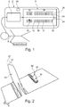
- Fig. 1 shows a schematic representation of an analysis device 2 according to the invention.
- the analysis device 2 has a multicapillary column 4 and an ion mobility spectrometer 6.
- the multi-capillary column 4 consists of a large number of bundled individual capillaries (not shown).
- Various Gas components of expiratory air require different lengths of time to pass through the multicapillary column 4. Expiratory air expelled by a patient 8 and as shown in FIG Fig. 1 is supplied to the multicapillary column 4, is thus separated into individual gas components with the aid of the multicapillary column.
- the time which a gas component needs to pass through the multicapillary column 4 is referred to as the retention time t R.
- the expired air or the gas components thereof are fed to the ion mobility spectrometer 6.
- the ion mobility spectrometer 6 comprises an ionization chamber section 10 and an adjoining drift chamber section 14 separated from the ionization chamber section 10 by a Bradbury-Nielsen grating 12.
- the Bradbury-Nielsen grid 12 controls penetration of the ions generated in the ionization chamber section 10 into the drift chamber section 14.
- the ions are accelerated to a Faraday plate 20, which is used to detect the ions, via an electric field generated by means of high-voltage rings 18.
- an aperture grating 22 is provided as a shielding grille for capacitive decoupling of the ions.
- an inlet opening 24 is provided for a drift gas, which flows through an interior 26 against a drift direction of the ions and prevents uncharged molecules or particles from entering the drift chamber section 14.
- drift time t D The duration of the passage of the ions through the drift chamber section 14 is referred to as the drift time t D.
- the analysis device 2 is configured to determine a proportion of an analyte contained in the expired air in the expired air.
- the analyte to be determined in the present invention is preferably an anesthetic, preferably propofol, which was administered intravenously to the patient 8 and which the patient exhales in the anesthetized state via the expiratory air.
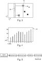
- FIG. 2 a chromatogram is shown which has two signal swings, which are generated by ionized gas components striking the Faraday plate 20 and are output by the analysis device 2 as a function of the retention time t R and the drift time t D.
- a first signal amplitude 28 and a second signal amplitude 30 are shown.
- the first signal deflection 28 is caused by the humidity of the exhaled air, in particular by reaction ions occurring during the ionization of the exhaled air and striking the Faraday plate 20, in particular H + (H 2 O) n ions or O 2 - (H 2 O) n ions.
- This first signal deflection 28 is essentially independent of the retention time after a certain drift time in the chromatogram and, due to the high relative humidity of exhaled air of over 95%, always represents a maximum, characteristic signal deflection in the chromatogram when analyzing expired air.
- the second signal amplitude 30 is caused by an analyte (for example an anesthetic, preferably propofol), the proportion of which in the expired air is to be determined.
- an analyte for example an anesthetic, preferably propofol
- a first maximum (absolute, quantitative value) 32 of the first signal deflection 28 is first determined.
- a second maximum (absolute, quantitative value) 34 of the second signal amplitude 30 is then determined.
- the proportion of the analyte in the expired air for example the ratio between the second maximum 34 and the first maximum 32 is formed and multiplied by the known and constant humidity proportion of the expired air of the patient 8.
- a calibration takes place according to the invention of the second maximum 34 of the second signal amplitude 30 at the first maximum 32 of the first signal amplitude 30.
- a first maximum 32 ′ of the first signal deflection 28 and a second maximum 34 ′ of the second signal deflection 30 are also indicated in dashed lines.
- the first maximum 32 'and the second maximum 34' would be obtained if the same exhaled air sample were fed to the analysis device 2 again at a later point in time.
- increasing maxima 32 ′, 34 ′ of the signal deflections 28, 30 are obtained.
- the present invention makes it possible to deal appropriately with continuously increasing absolute signal excursions, since according to the invention only the ratio between the second maximum 34, 34 'and the first maximum 32, 32' is to be formed.
- Fig. 3 a two-dimensional view of the chromatogram obtained is shown, in which various signal deflections obtained, for example again those in Fig. 2 signal swings 28 and 30 shown are shown.
- the signal deflection 28 represents a signal deflection which is characteristic of the moisture and can be found in a simple manner, since it is present after a certain drift time t D independent of the retention time t R.
- the analysis device 2 contains a database 36 in which two values each for the drift time t D and the retention time t R are stored for various analytes to be determined. These four values define a rectangular area 38 in the chromatogram in which the signal deflection for a specific analyte is located.
- the values for the drift time t D are preferably normalized at the first, characteristic signal deflection 28.
- the values contained in the database 36 define the rectangular area 38 in the chromatogram and only the maximum / the maximum absolute value in the defined rectangular area 38 needs to be determined .
- the analysis device 2 measures / calculates / determines, for example, a percentage ppb (parts per billion) of an analyte, preferably an anesthetic, in the expired air of a patient every minute and outputs the percentage received on a display.
- a doctor to continuously analyze the proportion of the anesthetic (propofol) in the expired air and to monitor the patient's anesthesia during a medical procedure. For example, if the doctor, as in Fig. 4 shown after 6 min and 7 min, notices that the proportion of the anesthetic in the expired air is decreasing, the patient 8 again administer the anesthetic intravenously.
- Fig. 5 shows a flow chart of steps to be carried out until the analysis device 2 according to the invention is ready for measurement. After switching on the device, initialization, a heating phase, rinsing and a zero measurement follow. These steps take less than 30 minutes. When it was mentioned above that a proportion measurement of the analyte in the expired air can be carried out immediately after the analysis device 2 has been switched on, this means that a proportion measurement can be carried out after 30 minutes at the latest.
Description
- Die Erfindung betrifft eine Analysevorrichtung zum Analysieren von Exspirationsluft eines Patienten, vorzugsweise zum Überwachen einer Narkose des Patienten während eines medizinischen Eingriffs, wobei die Analysevorrichtung konfiguriert ist, einen Anteil eines in der Exspirationsluft des Patienten enthaltenen Analyten in der Exspirationsluft zu bestimmen, mit: vorzugsweise einer Multikapillarsäule zum Vortrennen der zu analysierenden Exspirationsluft; und einem lonenbeweglichkeitsspektrometer, in welchem Gasbestandteile der Exspirationsluft ionisiert und hin zu einer Detektionsvorrichtung beschleunigt werden; wobei die Analysevorrichtung Signalausschläge ausgibt, welche durch die auf die Detektionsvorrichtung treffenden, ionisierten Gasbestandteile der Exspirationsluft erzeugt werden.
- Es sind aus dem Stand der Technik lonenbeweglichkeitsspektrometer bekannt, welche einer Detektion von chemischen Substanzen, Kampfstoffen, Sprengstoffen, Drogen, etc. dienen. Auch ist es beispielsweise aus der
DE 20 2013 105 685 U1 bekannt, solche lonenbeweglichkeitsspektrometer in der Medizin, beispielsweise in der Überwachung von Narkosen während medizinischer Eingriffe, einzusetzen. Dabei wird ein Narkosemittel, beispielsweise Propofol, in der Atemluft eines Patienten kontinuierlich analysiert. - Außerdem sind aus dem Stand der Technik Analysevorrichtungen bekannt, welche ein lonenbeweglichkeitsspektrometer in Kombination mit einer vorgeschalteten Multikapillarsäule aufweisen. Eine Multikapillarsäule ist eine gaschromatographische Säule, welche aus einer Vielzahl von gebündelten Einzelkapillaren besteht, die unterschiedliche Analyten verschieden lange zurückhalten. In anderen Worten benötigen die Gasbestandteile der Exspirationsluft für einen Durchtritt durch die Multikapillarsäule unterschiedlich lange, so dass eine Exspirationsluft-Probe mittels der Multikapillarsäule vorgetrennt werden kann (1. Trennung). Eine Durchtrittsdauer durch die Multikapillarsäule wird dabei als Retentionszeit bezeichnet.
- Nach der Vortrennung in der Multikapillarsäule gelangen die Gasbestandteile in das lonenbeweglichkeitsspektrometer, und zwar zunächst in einen lonisationskammerabschnitt des lonenbeweglichkeitsspektrometers, in welchem die Gasbestandteile der Exspirationsluft ionisiert werden. Dies geschieht mit Hilfe einer lonenquelle, beispielsweise mittels radioaktivem Nickel. Nach der Ionisierung durchlaufen die Ionen ein Sperrgitter und werden in einem Driftkammerabschnitt des lonenbeweglichkeitsspektrometers gegen die Strömungsrichtung eines Driftgases hin zu einer Detektionsvorrichtung beschleunigt. Ionen unterschiedlicher Masse bzw. Struktur erreichen hier unterschiedliche Driftgeschwindigkeiten, werden dadurch voneinander getrennt (2. Trennung) und treffen zeitlich nacheinander auf die Detektionsvorrichtung. Eine Durchtrittsdauer durch den Driftkammerabschnitt wird als Driftzeit bezeichnet. Die Beschleunigung der Ionen in dem lonenbeweglichkeitsspektrometer erfolgt mittels eines elektrischen Feldes. Die Analysevorrichtung gibt Signalausschläge aus, welche durch die auf die Detektionsvorrichtung treffenden, ionisierten Gasbestandteile der Exspirationsluft erzeugt werden.
- Im Stand der Technik gelang es bei den Versuchen, derartige Analysevorrichtungen zum Einsatz am Patienten während eines medizinischen Eingriffs bereitzustellen, bisher nicht, mit der hohen relativen Feuchte von Exspirationsluft geeignet umzugehen. Bisher wurde die hohe Feuchte von Exspirationsluft immer als für die Messergebnisse schädlich betrachtet. Der Stand der Technik gibt lediglich Lösungen, wie die feuchtebedingten Einflüsse verringert/ umgangen werden können und trotz der hohen Feuchte von Exspirationsluft brauchbare Messergebnisse erzielt werden können. Weiterhin hat der Stand der Technik den Nachteil, dass die Analysevorrichtung nach einem Einschalten derselben erst nach einem Zeitraum von mehreren Tagen für quantitative Messungen zur Analyse von Exspirationsluft verwendet werden kann, da über diesen Zeitraum die ausgegebenen Signalausschläge kontinuierlich ansteigen und sich erst danach auf einen konstanten Wert einpendeln.
- Vor diesem Hintergrund ist es Aufgabe der vorliegenden Erfindung, eine kompakt aufgebaute, anwendungsfalloptimierte Analysevorrichtung zum Analysieren von Exspirationsluft eines Patienten, vorzugsweise zum Überwachen einer Narkose des Patienten während eines medizinischen Eingriffs, bereitzustellen, mittels welcher verlässliche, exakte, wiederholgenaue und über einen längeren Zeitraum/ kontinuierliche Messungen unmittelbar nach einem Einschalten der Analysevorrichtung durchgeführt werden können.
- Diese Aufgabe wird durch eine Analysevorrichtung nach Anspruch 1 gelöst. Vorteilhafte Weiterbildungen und Ausführungsformen sind Gegenstand der Unteransprüche und/oder nachfolgend erläutert.
- Die Erfindung betrifft eine Analysevorrichtung zum Analysieren von Exspirationsluft eines Patienten, vorzugsweise zum Überwachen einer Narkose des Patienten während eines medizinischen Eingriffs, wobei die Analysevorrichtung konfiguriert ist, einen Anteil eines in der Exspirationsluft des Patienten enthaltenen Analyten in der Exspirationsluft zu bestimmen, mit: vorzugsweise einer Multikapillarsäule zum Vortrennen der zu analysierenden Exspirationsluft; und einem Ionenbeweglichkeitsspektrometer, in welchem Gasbestandteile der Exspirationsluft ionisiert und hin zu einer Detektionsvorrichtung beschleunigt werden; wobei die Analysevorrichtung Signalausschläge ausgibt, welche durch die auf die Detektionsvorrichtung treffenden, ionisierten Gasbestandteile der Exspirationsluft erzeugt werden. Ein Anteil des in der zu analysierenden Exspirationsluft enthaltenen, zu bestimmenden Analyten wird durch eine Kalibrierung des Signalausschlags des Analyten an einem Signalausschlag, welcher durch die Luftfeuchtigkeit von Exspirationsluft hervorgerufen wird, bestimmt.
- Dabei ist es vorteilhaft, wenn ein maximaler Signalausschlag des Analyten in Verhältnis mit einem maximalen Signalausschlag des durch die Luftfeuchtigkeit von Exspirationsluft hervorgerufenen Signalausschlags gesetzt wird, und der Anteil des Analyten in der Exspirationsluft unter Annahme einer bekannten und konstanten relativen Luftfeuchtigkeit von Exspirationsluft des Patienten, insbesondere einer relativen Luftfeuchtigkeit von 95 % oder einer patientenspezifisch im Voraus ermittelten relativen Luftfeuchtigkeit, bestimmt wird.
- In vorteilhafter Weise ist die Analysevorrichtung konfiguriert, durch die Kalibrierung des Signalausschlags des Analyten an dem durch die Luftfeuchtigkeit der Exspirationsluft hervorgerufenen Signalausschlag eine Anteilsmessung des Analyten in der Exspirationsluft bei kontinuierlich ansteigenden absoluten Signalausschlägen und somit unmittelbar nach einem Einschalten der Analysevorrichtung durchzuführen.
- In anderen Worten wird gemäß der vorliegenden Erfindung zunächst ein absoluter, quantitativer, maximaler Wert eines Signalausschlags, welcher durch die Luftfeuchtigkeit von Exspirationsluft erzeugt wird, ermittelt. Aufgrund der hohen Feuchte von Exspirationsluft kann dieser Wert relativ einfach ermittelt werden, da lediglich der größte (maximale) von der Analysevorrichtung ausgegebene Signalausschlag gesucht werden muss. Es wird schließlich angenommen, dass dieser absolute Wert einem bekannten und konstanten Feuchtigkeitsanteil von Exspirationsluft des Patienten entspricht. Dieser Feuchtigkeitsanteil kann beispielsweise immer auf einen festen Wert, beispielsweise 95%, gesetzt werden oder vor dem jeweiligen medizinischen Eingriff patientenspezifisch ermittelt werden. Will man nun den Anteil eines spezifischen Analyten in der Exspirationsluft bestimmen, muss nur noch ein absoluter, quantitativer, maximaler Wert eines Signalausschlags des Analyten ermittelt werden. Über eine Dreisatz-Beziehung kann dann der Anteil des Analyten in der Exspirationsluft berechnet werden. Dieses beschriebene Zurückrechnen auf den Anteil des Analyten wird in der vorliegenden Erfindung als Kalibrierung bezeichnet.
- Kern der vorliegenden Erfindung ist es somit, dass der bekannte und konstante Feuchteanteil von Exspirationsluft des Patienten zur Ermittlung des Anteils eines spezifischen Analyten genutzt wird. Weiterhin ist es Kern der vorliegenden Erfindung, dass für das Bestimmen des Anteils des Analyten lediglich das Verhältnis zwischen maximalem Signalausschlag des Analyten und maximalem feuchtebedingtem Signalausschlag bestimmt werden muss. Somit kann die erfindungsgemäße Analysevorrichtung auch bei kontinuierlich ansteigenden absoluten Werten, das heißt unmittelbar nach einem Einschalten der Analysevorrichtung, arbeiten.
- Bevorzugt ist der zu bestimmende Analyt ein Anästhetikum, vorzugsweise Propofol. Wird ein Anteil eines Anästhetikums in der Exspirationsluft eines Patienten bestimmt, können Rückschlüsse auf eine Narkosetiefe gezogen und somit die Narkose des Patienten während eines medizinischen Eingriffs überwacht werden.
- Es ist dabei von Vorteil, wenn die Analysevorrichtung konfiguriert ist, in vorbestimmten kurzen Zeitintervallen, insbesondere zumindest alle fünf Minuten, bevorzugt alle zwei Minuten, weiter bevorzugt jede Minute, den Anteil des Anästhetikums in der Exspirationsluft zu ermitteln und die erhaltenen Messwerte auf einem Display anzuzeigen.
- Ein vorteilhaftes Ausführungsbeispiel ist dadurch gekennzeichnet, dass die Gasbestandteile der Exspirationsluft für einen Durchtritt durch die Multikapillarsäule unterschiedlich lange benötigen und eine Durchtrittsdauer durch die Multikapillarsäule als Retentionszeit bezeichnet wird; das lonenbeweglichkeitsspektrometer einen lonisationskammerabschnitt, in welchem die Gasbestandteile der Exspirationsluft ionisiert werden, und einen Driftkammerabschnitt, in welchem die ionisierten Gasbestandteile hin zu der Detektionsvorrichtung beschleunigt werden, aufweist und eine Durchtrittsdauer durch den Driftkammerabschnitt als Driftzeit bezeichnet wird; und die Analysevorrichtung die Signalausschläge in einem Chromatogramm in Abhängigkeit von der Retentionszeit und der Driftzeit ausgibt.
- Bevorzugt liegt der durch die Luftfeuchtigkeit von Exspirationsluft hervorgerufene Signalausschlag im Wesentlichen unabhängig von der Retentionszeit nach einer bestimmten Driftzeit im Chromatogramm vor und stellt insbesondere einen maximalen Signalausschlag in dem Chromatogramm dar.
- In vorteilhafter Weise wird der durch die Luftfeuchtigkeit der Exspirationsluft hervorgerufene Signalausschlag durch bei der Ionisierung der Exspirationsluft entstehende, auf die Detektionsvorrichtung treffende Reaktionsionen, insbesondere H+(H2O)n-Ionen oder O2 -(H2O)n-Ionen erzeugt, welche sich in dem Chromatogramm durch einen charakteristischen Signalausschlag auszeichnen.
- Bevorzugt weist die Analysevorrichtung eine Datenbank auf, in welcher für verschiedene Analyten je zwei Werte für die Driftzeit und die Retentionszeit hinterlegt sind, wobei durch die vier in der Datenbank hinterlegten Werte ein Bereich in dem Chromatogramm definiert wird, in welchem sich der Signalausschlag für einen bestimmten Analyten befindet, wobei bevorzugt eine Driftzeitachse an dem durch die Luftfeuchtigkeit von Exspirationsluft hervorgerufenen Signalausschlag normiert ist.
- Die Erfindung wird nachfolgend mit Hilfe von Figuren weiter erläutert. Es zeigen:
- Fig. 1
- eine schematische Darstellung einer erfindungsgemäßen Analysevorrichtung;
- Fig. 2
- eine dreidimensionale Ansicht eines Chromatogramm, in welchem Signalausschläge in Abhängigkeit von einer Driftzeit und einer Retentionszeit dargestellt sind;
- Fig. 3
- eine zweidimensionale Ansicht eines Chromatogramms, in welchem Signalausschläge in Abhängigkeit von der Driftzeit und der Retentionszeit dargestellt sind;
- Fig. 4
- eine Displayanzeige der erfindungsgemäßen Analysevorrichtung; und
- Fig. 5
- ein Flussdiagramm von durchzuführenden Schritten bis die erfindungsgemäße Analysevorrichtung messbereit ist.
- Die Figuren sind lediglich schematischer Natur und dienen ausschließlich dem Verständnis der Erfindung. Gleiche Elemente sind dabei mit denselben Bezugszeichen versehen.
-
Fig. 1 zeigt eine schematische Darstellung einer erfindungsgemäßen Analysevorrichtung 2. Die Analysevorrichtung 2 weist eine Multikapillarsäule 4 und ein lonenbeweglichkeitsspektrometer 6 auf. Die Multikapillarsäule 4 besteht aus einer Vielzahl von gebündelten Einzelkapillaren (nicht dargestellt). Verschiedene Gasbestandteile von Exspirationsluft benötigen für einen Durchtritt durch die Multikapillarsäule 4 unterschiedlich lange. Exspirationsluft, welche von einem Patienten 8 ausgestoßen wird und wie inFig. 1 gezeigt der Multikapillarsäule 4 zugeführt wird, wird somit mit Hilfe der Multikapillarsäule in einzelne Gasbestandteile aufgetrennt. Die Zeit, welche ein Gasbestandteil für die Passage durch die Multikapillarsäule 4 benötigt, wird als Retentionszeit tR bezeichnet. - Nach einer ersten Trennung mittels der Multikapillarsäule 4 wird die Exspirationsluft bzw. werden die Gasbestandteile derselben dem lonenbeweglichkeitsspektrometer 6 zugeführt. Das lonenbeweglichkeitsspektrometer 6 umfasst einen lonisationskammerabschnitt 10 und einen daran angrenzenden, durch ein Bradbury-Nielsen-Gitter 12 von dem lonisationskammerabschnitt 10 getrennten Driftkammerabschnitt 14. In dem lonisationskammerabschnitt 10 werden die Gasbestandteile der Exspirationsluft mittels einer lonisationsquelle 16 (beispielsweise radioaktives Nickel) ionisiert. Das Bradbury-Nielsen-Gitter 12 steuert ein Eindringen der in dem lonisationskammerabschnitt 10 erzeugten Ionen in den Driftkammerabschnitt 14. Über ein mittels Hochspannungsringe 18 erzeugtes elektrisches Feld werden die Ionen hin zu einer Faraday-Platte 20 beschleunigt, welche einer Detektion der Ionen dient. Unmittelbar vor der Faraday-Platte 20 ist ein Apertur-Gitter 22 als Abschirmgitter zur kapazitiven Entkopplung der Ionen vorgesehen. An der die Faraday-Platte 20 aufweisenden Seite des Driftkammerabschnitts 14 ist eine Einlassöffnung 24 für ein Driftgas vorgesehen, welches einen Innenraum 26 entgegen einer Driftrichtung der Ionen durchströmt und verhindert, dass ungeladene Moleküle oder Partikel in den Driftkammerabschnitt 14 hinein gelangen.
- Ionen unterschiedlicher Masse bzw. Struktur erreichen in dem Driftkammerabschnitt 14 unterschiedliche Driftgeschwindigkeiten, werden dadurch voneinander getrennt (zweite Trennung) und treffen zeitlich nacheinander auf die Faraday-Platte 20. Eine Durchtrittsdauer der Ionen durch den Driftkammerabschnitt 14 wird dabei als Driftzeit tD bezeichnet.
- Die Analysevorrichtung 2 ist konfiguriert, einen Anteil eines in der Exspirationsluft enthaltenen Analyten in der Exspirationsluft zu bestimmen. Der zu bestimmende Analyt ist in der vorliegenden Erfindung bevorzugt ein Anästhetikum, vorzugsweise Propofol, welches dem Patienten 8 intravenös verabreicht wurde und welches dieser im narkotisierten Zustand über die Exspirationsluft ausatmet.
- Wie genau der Anteil des in der Exspirationsluft enthaltenen Analyten erfindungsgemäß bestimmt wird, wird mit Bezugnahme auf
Fig. 2 erläutert. InFig. 2 ist ein Chromatogramm dargestellt, welches beispielhaft zwei Signalausschläge aufweist, welche durch auf die Faraday-Platte 20 treffende, ionisierte Gasbestandteile erzeugt werden und von der Analysevorrichtung 2 in Abhängigkeit von der Retentionszeit tR und der Driftzeit tD ausgegeben werden. - In
Fig. 2 ist ein erster Signalausschlag 28 und ein zweiter Signalausschlag 30 dargestellt. Der erste Signalausschlag 28 wird durch die Luftfeuchtigkeit der Exspirationsluft hervorgerufen, insbesondere durch bei der Ionisierung der Exspirationsluft entstehende, auf die Faraday-Platte 20 treffende Reaktionsionen, insbesondere H+(H2O)n-Ionen oder O2 -(H2O)n-Ionen. Dieser erste Signalausschlag 28 liegt im Wesentlichen unabhängig von der Retentionszeit nach einer bestimmten Driftzeit im Chromatogramm vor und stellt aufgrund der hohen relativen Feuchte von Exspirationsluft von über 95% bei einer Analyse von Exspirationsluft immer einen maximalen, charakteristischen Signalausschlag in dem Chromatogramm dar. - Der zweite Signalausschlag 30 wird durch einen Analyten (beispielsweise ein Anästhetikum, vorzugsweise Propofol) hervorgerufen, dessen Anteil in der Exspirationsluft zu bestimmen ist.
- Erfindungsgemäß wird zunächst ein erstes Maximum (absoluter, quantitativer Wert) 32 des ersten Signalausschlags 28 bestimmt. Anschließend wird ein zweites Maximum (absoluter, quantitativer Wert) 34 des zweiten Signalausschlags 30 bestimmt. Um nun den Anteil des Analyten in der Exspirationsluft zu erhalten, wird beispielsweise das Verhältnis zwischen zweitem Maximum 34 und erstem Maximum 32 gebildet und mit dem bekannten und konstanten Luftfeuchtigkeitsanteil der Exspirationsluft des Patienten 8 multipliziert. In anderen Worten erfolgt erfindungsgemäß eine Kalibrierung des zweiten Maximums 34 des zweiten Signalausschlags 30 an dem ersten Maximum 32 des ersten Signalausschlags 30.
- In
Fig. 2 sind in gestrichelten Linien noch ein erstes Maximum 32' des ersten Signalausschlags 28 und ein zweites Maximum 34' des zweiten Signalausschlags 30 angedeutet. Das erste Maximum 32' und das zweite Maximum 34' würde erhalten werden, wenn dieselbe Exspirationsluft-Probe der Analysevorrichtung 2 zu einem späteren Zeitpunkt noch einmal zugeführt werden würde. In anderen Worten werden grundsätzlich mit zunehmender Zeitdauer nach einem Einschalten der Analysevorrichtung 2 zunehmende Maxima 32', 34' der Signalausschläge 28, 30 erhalten. Die vorliegende Erfindung ermöglicht es, geeignet mit kontinuierlich ansteigenden absoluten Signalausschlägen umzugehen, da erfindungsgemäß immer nur das Verhältnis zwischen zweitem Maximum 34, 34' und erstem Maximum 32, 32' zu bilden ist. - In
Fig. 3 ist eine zweidimensionale Ansicht des erhaltenen Chromatogramms dargestellt, in welchem verschiedene erhaltene Signalausschläge, beispielsweise wiederum die inFig. 2 dargestellten Signalausschläge 28 und 30 dargestellt sind. Wie voranstehend schon erläutert, stellt der Signalausschlag 28 einen für die Feuchte charakteristischen Signalausschlag dar und kann in einfacher Weise gefunden werden, da er nach einer bestimmten Driftzeit tD unabhängig von der Retentionszeit tR vorliegt. - Die Analysevorrichtung 2 enthält eine Datenbank 36, in welcher für verschiedene zu bestimmende Analyten je zwei Werte für die Driftzeit tD und die Retentionszeit tR hinterlegt sind. Durch diese vier Werte wird in dem Chromatogramm ein rechteckiger Bereich 38 definiert, in welchem sich der Signalausschlag für einen bestimmten Analyt befindet. Bevorzugt sind die Werte für die Driftzeit tD dabei an dem ersten, charakteristischen Signalausschlag 28 normiert.
- Soll nun das zweite Maximum 34 des zweiten Signalausschlags 30 bestimmt werden, wird durch die in der Datenbank 36 enthaltenen Werte der rechteckige Bereich 38 in dem Chromatogramm definiert und es muss nur noch das Maximum/ der maximale absolute Wert in dem definierten rechteckigen Bereich 38 bestimmt werden.
- Wie in
Fig. 4 gezeigt misst/berechnet/ermittelt die Analysevorrichtung 2 beispielsweise jede Minute einen Anteil ppb (parts per billion) eines Analyten, vorzugsweise eines Anästhetikums, in der Exspirationsluft eines Patienten und gibt den jeweils erhaltenen Anteil auf einem Display aus. Dadurch wird es einem Arzt ermöglicht, kontinuierlich den Anteil des Anästhetikums (Propofol) in der Exspirationsluft zu analysieren und eine Narkose des Patienten während eines medizinischen Eingriffs zu überwachen. Beispielsweise kann der Arzt, wenn er wie inFig. 4 dargestellt nach 6 min bzw. 7 min merkt, dass der Anteil des Anästhetikums in der Exspirationsluft zurückgeht, dem Patienten 8 das Anästhetikum erneut intravenös verabreichen. -
Fig. 5 zeigt ein Flussdiagramm von durchzuführenden Schritten bis die erfindungsgemäße Analysevorrichtung 2 messbereit ist. Nach einem Einschalten des Geräts folgen eine Initialisierung, eine Aufheizphase, eine Spülung und eine Nullmessung. Diese Schritte dauern weniger als 30 min. Wenn voranstehend davon die Rede war, dass eine Anteilsmessung des Analyten in der Exspirationsluft unmittelbar nach einem Einschalten der Analysevorrichtung 2 durchgeführt werden kann, ist somit gemeint, dass eine Anteilsmessung spätestens nach 30 min durchgeführt werden kann. -
- 2
- Analysevorrichtung
- 4
- Multikapillarsäule
- 6
- Ionenbeweglichkeitsspektrometer
- 8
- Patient
- 10
- Ionisationskammerabschnitt
- 12
- Bradbury-Nielsen-Gitter
- 14
- Driftkammerabschnitt
- 16
- lonisationsquelle
- 18
- Hochspannungsring
- 20
- Faraday-Platte
- 22
- Apertur-Gitter
- 24
- Einlassöffnung
- 26
- Innenraum
- 28
- erster Signalausschlag
- 30
- zweiter Signalausschlag
- 32, 32'
- erstes Maximum
- 34, 34'
- zweites Maximum
- 36
- Datenbank
- 38
- rechteckiger Bereich
- 40
- Display
Claims (9)
- Analysevorrichtung (2), angepasst zum Analysieren von Exspirationsluft eines Patienten (8), vorzugsweise zum Überwachen einer Narkose des Patienten (8) während eines medizinischen Eingriffs, wobei die Analysevorrichtung (2) konfiguriert ist, einen Anteil eines in der Exspirationsluft des Patienten (8) enthaltenen Analyten in der Exspirationsluft zu bestimmen, mit: zumindest einer Multikapillarsäule (4), angepasst zum Vortrennen der zu analysierenden Exspirationsluft; und einem lonenbeweglichkeitsspektrometer (6), in welchem Gasbestandteile der Exspirationsluft ionisiert und hin zu einer Detektionsvorrichtung (20) beschleunigt werden; wobei die Analysevorrichtung (2) angepasst ist, Signalausschläge (28, 30) auszugeben, welche durch die auf die Detektionsvorrichtung (20) treffenden, ionisierten Gasbestandteile der Exspirationsluft erzeugt werden,
gekennzeichnet durch
eine Bestimmungseinheit (CPU), die dafür angepasst ist, einen Anteil des in der zu analysierenden Exspirationsluft enthaltenen, zu bestimmenden Analyten durch eine Kalibrierung des Signalausschlags (30) des Analyten an einem Signalausschlag (28), welcher durch die Luftfeuchtigkeit von Exspirationsluft hervorgerufen wird, zu bestimmen. - Analysevorrichtung (2) nach Anspruch 1, dadurch gekennzeichnet, dass ein maximaler Signalausschlag (34, 34') des Analyten in Verhältnis mit einem maximalen Signalausschlag (32, 32') des durch die Luftfeuchtigkeit von Exspirationsluft hervorgerufenen Signalausschlags (28) gesetzt wird, und der Anteil des Analyten in der Exspirationsluft unter Annahme einer bekannten und konstanten relativen Luftfeuchtigkeit von Exspirationsluft, insbesondere einer relativen Luftfeuchtigkeit von 95 % oder einer patientenspezifisch im Voraus ermittelten relativen Luftfeuchtigkeit, bestimmt wird.
- Analysevorrichtung (2) nach Anspruch 1 oder 2, dadurch gekennzeichnet, dass diese konfiguriert ist, durch die Kalibrierung des Signalausschlags (30) des Analyten an dem durch die Luftfeuchtigkeit der Exspirationsluft hervorgerufenen Signalausschlag (28) eine Anteilsmessung des Analyten in der Exspirationsluft bei kontinuierlich ansteigenden absoluten Signalausschlägen (32, 32', 34, 34') und somit unmittelbar nach einem Einschalten der Analysevorrichtung (2) durchzuführen.
- Analysevorrichtung (2) nach einem der vorhergehenden Ansprüche, dadurch gekennzeichnet, dass der zu bestimmende Analyt ein Anästhetikum, vorzugsweise Propofol, ist.
- Analysevorrichtung (2) nach Anspruch 4, dadurch gekennzeichnet, dass diese konfiguriert ist, in vorbestimmten kurzen Zeitintervallen, insbesondere zumindest alle fünf Minuten, bevorzugt alle zwei Minuten, weiter bevorzugt jede Minute, den Anteil des Anästhetikums in der Exspirationsluft zu ermitteln und die erhaltenen Messwerte auf einem Display (40) anzuzeigen.
- Analysevorrichtung (2) nach einem der vorhergehenden Ansprüche, wobei
die Gasbestandteile der Exspirationsluft für einen Durchtritt durch eine Multikapillarsäule (4) unterschiedlich lange benötigen und eine Durchtrittsdauer durch die Multikapillarsäule (4) als Retentionszeit (tR) bezeichnet wird; wobei
das lonenbeweglichkeitsspektrometer (6) einen lonisationskammerabschnitt (10), in welchem die Gasbestandteile der Exspirationsluft ionisiert werden, und einen Driftkammerabschnitt (14), in welchem die ionisierten Gasbestandteile hin zu der Detektionsvorrichtung (20) beschleunigt werden, aufweist und eine Durchtrittsdauer durch den Driftkammerabschnitt (14) als Driftzeit (tD) bezeichnet wird; und wobei
die Analysevorrichtung (2) die Signalausschläge (28, 30) in einem Chromatogramm in Abhängigkeit von der Retentionszeit (tR) und der Driftzeit (tD) ausgibt. - Analysevorrichtung (2) nach Anspruch 6, dadurch gekennzeichnet, dass der durch die Luftfeuchtigkeit von Exspirationsluft hervorgerufene Signalausschlag (28) im Wesentlichen unabhängig von der Retentionszeit (tR) nach einer bestimmten Driftzeit (tD) im Chromatogramm vorliegt und einen maximalen Signalausschlag (32, 32') in dem Chromatogramm darstellt.
- Analysevorrichtung (2) nach Anspruch 6 oder 7, dadurch gekennzeichnet, dass der durch die Luftfeuchtigkeit der Exspirationsluft hervorgerufene Signalausschlag (28) durch bei der Ionisierung der Exspirationsluft entstehende, auf die Detektionsvorrichtung (20) treffende Reaktionsionen, insbesondere H+(H2O)n-Ionen oder O2-(H2O)n-Ionen erzeugt wird, welche sich in dem Chromatogramm durch einen charakteristischen Signalausschlag (28) auszeichnen.
- Analysevorrichtung (2) nach einem der Ansprüche 6 bis 8, ferner gekennzeichnet durch eine Datenbank (36), in welcher für verschiedene Analyten je zwei Werte für die Driftzeit (tD) und die Retentionszeit (tR) hinterlegt sind, wobei durch diese vier in der Datenbank (36) hinterlegten Werte ein Bereich (38) in dem Chromatogramm definiert wird, in welchem sich der Signalausschlag (30) für einen bestimmten Analyten befindet, wobei bevorzugt eine Driftzeitachse an dem durch die Luftfeuchtigkeit von Exspirationsluft hervorgerufenen Signalausschlag (28) normiert ist.
Applications Claiming Priority (2)
| Application Number | Priority Date | Filing Date | Title |
|---|---|---|---|
| DE102017111459 | 2017-05-24 | ||
| PCT/EP2018/063720 WO2018215618A1 (de) | 2017-05-24 | 2018-05-24 | Analysevorrichtung zum analysieren von exspirationsluft |
Publications (2)
| Publication Number | Publication Date |
|---|---|
| EP3629917A1 EP3629917A1 (de) | 2020-04-08 |
| EP3629917B1 true EP3629917B1 (de) | 2021-07-21 |
Family
ID=64395376
Family Applications (4)
| Application Number | Title | Priority Date | Filing Date |
|---|---|---|---|
| EP18728562.2A Active EP3629917B1 (de) | 2017-05-24 | 2018-05-24 | Analysevorrichtung zum analysieren von exspirationsluft |
| EP18729604.1A Withdrawn EP3631434A1 (de) | 2017-05-24 | 2018-05-24 | Driftröhre für ionenbeweglichkeitsspektrometr mit integrierter multikapillarsäule |
| EP18728081.3A Withdrawn EP3629916A1 (de) | 2017-05-24 | 2018-05-24 | Elektrodenanordnung für eine driftröhre |
| EP18728563.0A Withdrawn EP3631433A1 (de) | 2017-05-24 | 2018-05-24 | Driftröhre mit modifizierter oberflächengüte zur verwendung in einem ionenbeweglichkeitsspektrometer |
Family Applications After (3)
| Application Number | Title | Priority Date | Filing Date |
|---|---|---|---|
| EP18729604.1A Withdrawn EP3631434A1 (de) | 2017-05-24 | 2018-05-24 | Driftröhre für ionenbeweglichkeitsspektrometr mit integrierter multikapillarsäule |
| EP18728081.3A Withdrawn EP3629916A1 (de) | 2017-05-24 | 2018-05-24 | Elektrodenanordnung für eine driftröhre |
| EP18728563.0A Withdrawn EP3631433A1 (de) | 2017-05-24 | 2018-05-24 | Driftröhre mit modifizierter oberflächengüte zur verwendung in einem ionenbeweglichkeitsspektrometer |
Country Status (6)
| Country | Link |
|---|---|
| US (1) | US20200170571A1 (de) |
| EP (4) | EP3629917B1 (de) |
| CN (3) | CN110662486A (de) |
| ES (1) | ES2890574T3 (de) |
| RU (1) | RU2761078C2 (de) |
| WO (4) | WO2018215622A1 (de) |
Family Cites Families (30)
| Publication number | Priority date | Publication date | Assignee | Title |
|---|---|---|---|---|
| GB2217103B (en) * | 1988-04-06 | 1992-09-23 | Graseby Ionics Ltd | Ion mobility detector |
| DE4130810C1 (de) * | 1991-09-17 | 1992-12-03 | Bruker Saxonia Analytik Gmbh, O-7050 Leipzig, De | |
| US6509562B1 (en) * | 1999-09-16 | 2003-01-21 | Rae Systems, Inc. | Selective photo-ionization detector using ion mobility spectrometry |
| DE10121262A1 (de) * | 2001-04-30 | 2002-11-14 | Siemens Ag | Vorrichtung zur quantitativen Messung von Stickoxiden in der Ausatemluft und Verwendung |
| ITMI20011193A1 (it) * | 2001-06-06 | 2002-12-06 | Getters Spa | Metodo per la misura mediante spettroscopia di mobilita' ionica dellaconcentrazione di acqua in argon, idrogeno, azoto e elio |
| US6685803B2 (en) * | 2001-06-22 | 2004-02-03 | Applied Materials, Inc. | Plasma treatment of processing gases |
| US7155812B1 (en) * | 2002-09-05 | 2007-01-02 | Sandia Corporation | Method for producing a tube |
| DE102006006683B4 (de) * | 2006-02-14 | 2008-02-21 | Bruker Daltonik Gmbh | Driftröhre für ein Ionenmobilitätsspektrometer mit integriertem Gaskanal |
| CN101093211B (zh) * | 2006-06-21 | 2010-05-12 | 中国科学院电子学研究所 | 用于离子迁移率谱仪漂移管的瞬态漂移电场方法 |
| JP4677530B2 (ja) * | 2006-12-12 | 2011-04-27 | 国立大学法人大阪大学 | プラズマ生成装置およびプラズマ生成方法 |
| DE102007033906A1 (de) * | 2007-07-20 | 2009-01-29 | Gesellschaft zur Förderung der Analytischen Wissenschaften e.V. | Verfahren zur Analyse von Gasen, insbesondere zur Analyse der menschlichen Ausatemluft |
| US7880137B2 (en) * | 2007-12-28 | 2011-02-01 | Morpho Detection, Inc. | Electrode design for an ion spectrometer |
| US7709788B2 (en) * | 2007-12-31 | 2010-05-04 | Implant Sciences Corporation | Chemical calibration method and system |
| DE202008007748U1 (de) * | 2008-06-05 | 2008-09-18 | Filt Lungen- Und Thoraxdiagnostik Gmbh | Vorrichtung zur Konditionierung von Gasen |
| EP2312612B1 (de) * | 2009-10-16 | 2017-03-08 | Korea Institute Of Machinery & Materials | Plasmareaktor zur Reduzierung von Gefahrstoffen und Ansteuerungsverfahren dafür |
| EP2531825A4 (de) * | 2010-01-29 | 2014-04-02 | Univ Texas | Hervorragendes analysegerät für raman-spektren mit hohem eintrittskegel, hoher auflösung, hoher übertragungsrate und hoher quantumseffizienz sowie starker hintergrundreduzierung |
| DE112011102013B4 (de) * | 2010-06-17 | 2016-09-29 | Step Sensortechnik Und Elektronik Pockau Gmbh | Verfahren für die lonenmobilitätsspektrometrie |
| EP2428797B1 (de) * | 2010-09-14 | 2016-05-18 | Airsense Analytics GmbH | Vorrichtung zur detektion und identifizierung von gasen mittels ionenmobilitätsspektrometrie |
| US8922219B2 (en) * | 2010-11-30 | 2014-12-30 | General Electric Company | Photo-ionization detectors and associated methods thereof |
| CN102539513A (zh) * | 2010-12-09 | 2012-07-04 | 苏州生物医学工程技术研究所 | 一种用于患者疾病的无创检测装置及其检测方法 |
| ITMI20110535A1 (it) * | 2011-03-31 | 2012-10-01 | Simone Cristoni | Sistema di analisi per l'analisi chimica quantitativa di campioni, in particolare in ambito medico, con calibrazione della risposta strumentale della strumentazione utilizzata per rilevare i dati quantitativi degli analiti presenti nei campioni anali |
| KR20140056175A (ko) * | 2011-04-27 | 2014-05-09 | 임플란트 사이언스 코포레이션 | Faims 셀이 삽입된 이온 이동성 분광 측정기 장치 |
| US9089279B2 (en) * | 2011-12-29 | 2015-07-28 | General Electric Company | Ion-based breath analysis system |
| DE102013112921A1 (de) * | 2013-11-22 | 2015-05-28 | IMSPEX DIAGNOSTICS Ltd. | Verfahren zur Messung der menschlichen Ausatemluft mittels Gaschromatografie-Ionenmobilitätsspektrometrie |
| DE202013105685U1 (de) | 2013-12-13 | 2015-03-17 | B & S Analytik Gmbh | Ionenbeweglichkeitsspektrometer |
| CN103776893B (zh) * | 2014-02-17 | 2016-09-21 | 哈尔滨工业大学(威海) | 一种介质阻挡放电电离源离子迁移谱仪 |
| CN105353023B (zh) * | 2014-08-20 | 2018-10-16 | 布鲁克道尔顿公司 | 离子迁移谱迁移轴校正方法和仪器 |
| EP3237084A4 (de) * | 2014-12-24 | 2017-12-06 | Biometry Inc. | Gaschromatografischer miniteststreifen zu anwendung am behandlungsort und verfahren zur messung von analyten |
| CN107064361B (zh) * | 2014-12-31 | 2020-03-27 | 同方威视技术股份有限公司 | 检测设备和检测方法 |
| US20180172635A1 (en) * | 2016-12-15 | 2018-06-21 | Rapiscan Systems, Inc. | Methods and devices for moisture-based calibration |
-
2018
- 2018-05-24 WO PCT/EP2018/063724 patent/WO2018215622A1/de unknown
- 2018-05-24 WO PCT/EP2018/063720 patent/WO2018215618A1/de unknown
- 2018-05-24 EP EP18728562.2A patent/EP3629917B1/de active Active
- 2018-05-24 CN CN201880034219.XA patent/CN110662486A/zh active Pending
- 2018-05-24 WO PCT/EP2018/063721 patent/WO2018215619A1/de unknown
- 2018-05-24 ES ES18728562T patent/ES2890574T3/es active Active
- 2018-05-24 RU RU2019143086A patent/RU2761078C2/ru active
- 2018-05-24 CN CN201880033302.5A patent/CN110678121B/zh active Active
- 2018-05-24 CN CN201880034232.5A patent/CN110662959A/zh active Pending
- 2018-05-24 EP EP18729604.1A patent/EP3631434A1/de not_active Withdrawn
- 2018-05-24 EP EP18728081.3A patent/EP3629916A1/de not_active Withdrawn
- 2018-05-24 WO PCT/EP2018/063723 patent/WO2018215621A1/de unknown
- 2018-05-24 EP EP18728563.0A patent/EP3631433A1/de not_active Withdrawn
- 2018-05-24 US US16/616,057 patent/US20200170571A1/en not_active Abandoned
Also Published As
| Publication number | Publication date |
|---|---|
| RU2761078C2 (ru) | 2021-12-03 |
| EP3631434A1 (de) | 2020-04-08 |
| EP3629916A1 (de) | 2020-04-08 |
| WO2018215619A1 (de) | 2018-11-29 |
| WO2018215621A1 (de) | 2018-11-29 |
| US20200170571A1 (en) | 2020-06-04 |
| CN110678121B (zh) | 2022-07-26 |
| CN110678121A (zh) | 2020-01-10 |
| RU2019143086A3 (de) | 2021-07-12 |
| EP3631433A1 (de) | 2020-04-08 |
| CN110662959A (zh) | 2020-01-07 |
| CN110662486A (zh) | 2020-01-07 |
| EP3629917A1 (de) | 2020-04-08 |
| ES2890574T3 (es) | 2022-01-20 |
| RU2019143086A (ru) | 2021-06-24 |
| WO2018215618A1 (de) | 2018-11-29 |
| WO2018215622A1 (de) | 2018-11-29 |
Similar Documents
| Publication | Publication Date | Title |
|---|---|---|
| EP2095868B1 (de) | Vorrichtung für die Zufuhr von Gasen zu einer Analyseeinrichtung | |
| DE102007017055B4 (de) | Messung der Mobilität massenselektierter Ionen | |
| CH615532A5 (de) | ||
| EP2428797B1 (de) | Vorrichtung zur detektion und identifizierung von gasen mittels ionenmobilitätsspektrometrie | |
| DE112019000840T5 (de) | Chromatographie-Massenspektrometrie-Verfahren und Chromatograph-Massenspektrometer | |
| DE2705185A1 (de) | Verfahren zum analysieren von gasgemischen und zur durchfuehrung des verfahrens geeigneter elektroneneinfangdetektor | |
| EP3629917B1 (de) | Analysevorrichtung zum analysieren von exspirationsluft | |
| DE4106602A1 (de) | Metalloberflaechen von analyse- und ionisationsvorrichtungen fuer proben | |
| DE102007033906A1 (de) | Verfahren zur Analyse von Gasen, insbesondere zur Analyse der menschlichen Ausatemluft | |
| DE202013105685U1 (de) | Ionenbeweglichkeitsspektrometer | |
| DE2402728C3 (de) | Vorrichtung zum Analysieren einer Oberflachenschicht durch Ionenzerstreuung | |
| DE202007010129U1 (de) | Vorrichtung zur Analyse von Gasen | |
| DE102016217589A1 (de) | Winkelaufgelöste analyse des ausgasverhaltens von vakuum-bauteilen | |
| WO2018196958A1 (de) | Verfahren und anordnung zur kalibrierung einer chromatographischen analyse von komplexen stoffgemischen, insbesondere von atemgasen | |
| EP3399311B1 (de) | Vorrichtung zur vorbehandlung eines zu untersuchenden gases | |
| DE102022124919A1 (de) | Chemisches Analysegerät, Wasserstoffsensoreinheit für ein chemisches Analysegerät und Verfahren zum Betreiben eines chemischen Analysegerätes | |
| DE19637205C2 (de) | Massenspektroskopie-Verfahren | |
| DE102007059458A1 (de) | Verfahren zur Auswertung analytbezogener Signale aus mittels der Ionenbeweglichkeitsspektrometrie aufgenommenen IMS-Spektren | |
| Patterson | Method to analyze gas mixtures and suitable electron capture-detector to perform the method | |
| EP0914606A1 (de) | Anordnung zur schnellen und hochempfindlichen registrierung von duftstoffgemischen in der atmosphäre und ein analyseverfahren dafür | |
| WO2017207249A1 (de) | Bestimmung einer gaskonzentration | |
| DE2305557A1 (de) | Massenspektrometer | |
| DE7001426U (de) | Vorrichtung zur messung der profils von profilstaeben. | |
| DE202007010128U1 (de) | Vorrichtung zur Analyse von Gasen | |
| DE10338204A1 (de) | Verfahren zur Überwachung einer Konzentration wenigstens eines Analyten in einem Trägergas |
Legal Events
| Date | Code | Title | Description |
|---|---|---|---|
| STAA | Information on the status of an ep patent application or granted ep patent |
Free format text: STATUS: UNKNOWN |
|
| STAA | Information on the status of an ep patent application or granted ep patent |
Free format text: STATUS: THE INTERNATIONAL PUBLICATION HAS BEEN MADE |
|
| PUAI | Public reference made under article 153(3) epc to a published international application that has entered the european phase |
Free format text: ORIGINAL CODE: 0009012 |
|
| STAA | Information on the status of an ep patent application or granted ep patent |
Free format text: STATUS: REQUEST FOR EXAMINATION WAS MADE |
|
| 17P | Request for examination filed |
Effective date: 20191219 |
|
| AK | Designated contracting states |
Kind code of ref document: A1 Designated state(s): AL AT BE BG CH CY CZ DE DK EE ES FI FR GB GR HR HU IE IS IT LI LT LU LV MC MK MT NL NO PL PT RO RS SE SI SK SM TR |
|
| AX | Request for extension of the european patent |
Extension state: BA ME |
|
| DAV | Request for validation of the european patent (deleted) | ||
| DAX | Request for extension of the european patent (deleted) | ||
| GRAP | Despatch of communication of intention to grant a patent |
Free format text: ORIGINAL CODE: EPIDOSNIGR1 |
|
| STAA | Information on the status of an ep patent application or granted ep patent |
Free format text: STATUS: GRANT OF PATENT IS INTENDED |
|
| INTG | Intention to grant announced |
Effective date: 20210211 |
|
| GRAS | Grant fee paid |
Free format text: ORIGINAL CODE: EPIDOSNIGR3 |
|
| GRAA | (expected) grant |
Free format text: ORIGINAL CODE: 0009210 |
|
| STAA | Information on the status of an ep patent application or granted ep patent |
Free format text: STATUS: THE PATENT HAS BEEN GRANTED |
|
| AK | Designated contracting states |
Kind code of ref document: B1 Designated state(s): AL AT BE BG CH CY CZ DE DK EE ES FI FR GB GR HR HU IE IS IT LI LT LU LV MC MK MT NL NO PL PT RO RS SE SI SK SM TR |
|
| REG | Reference to a national code |
Ref country code: GB Ref legal event code: FG4D Free format text: NOT ENGLISH |
|
| REG | Reference to a national code |
Ref country code: CH Ref legal event code: EP |
|
| REG | Reference to a national code |
Ref country code: DE Ref legal event code: R096 Ref document number: 502018006229 Country of ref document: DE |
|
| REG | Reference to a national code |
Ref country code: AT Ref legal event code: REF Ref document number: 1411834 Country of ref document: AT Kind code of ref document: T Effective date: 20210815 |
|
| REG | Reference to a national code |
Ref country code: IE Ref legal event code: FG4D Free format text: LANGUAGE OF EP DOCUMENT: GERMAN |
|
| REG | Reference to a national code |
Ref country code: NL Ref legal event code: FP |
|
| REG | Reference to a national code |
Ref country code: LT Ref legal event code: MG9D |
|
| REG | Reference to a national code |
Ref country code: ES Ref legal event code: FG2A Ref document number: 2890574 Country of ref document: ES Kind code of ref document: T3 Effective date: 20220120 |
|
| PG25 | Lapsed in a contracting state [announced via postgrant information from national office to epo] |
Ref country code: HR Free format text: LAPSE BECAUSE OF FAILURE TO SUBMIT A TRANSLATION OF THE DESCRIPTION OR TO PAY THE FEE WITHIN THE PRESCRIBED TIME-LIMIT Effective date: 20210721 Ref country code: FI Free format text: LAPSE BECAUSE OF FAILURE TO SUBMIT A TRANSLATION OF THE DESCRIPTION OR TO PAY THE FEE WITHIN THE PRESCRIBED TIME-LIMIT Effective date: 20210721 Ref country code: SE Free format text: LAPSE BECAUSE OF FAILURE TO SUBMIT A TRANSLATION OF THE DESCRIPTION OR TO PAY THE FEE WITHIN THE PRESCRIBED TIME-LIMIT Effective date: 20210721 Ref country code: RS Free format text: LAPSE BECAUSE OF FAILURE TO SUBMIT A TRANSLATION OF THE DESCRIPTION OR TO PAY THE FEE WITHIN THE PRESCRIBED TIME-LIMIT Effective date: 20210721 Ref country code: NO Free format text: LAPSE BECAUSE OF FAILURE TO SUBMIT A TRANSLATION OF THE DESCRIPTION OR TO PAY THE FEE WITHIN THE PRESCRIBED TIME-LIMIT Effective date: 20211021 Ref country code: PT Free format text: LAPSE BECAUSE OF FAILURE TO SUBMIT A TRANSLATION OF THE DESCRIPTION OR TO PAY THE FEE WITHIN THE PRESCRIBED TIME-LIMIT Effective date: 20211122 Ref country code: BG Free format text: LAPSE BECAUSE OF FAILURE TO SUBMIT A TRANSLATION OF THE DESCRIPTION OR TO PAY THE FEE WITHIN THE PRESCRIBED TIME-LIMIT Effective date: 20211021 Ref country code: LT Free format text: LAPSE BECAUSE OF FAILURE TO SUBMIT A TRANSLATION OF THE DESCRIPTION OR TO PAY THE FEE WITHIN THE PRESCRIBED TIME-LIMIT Effective date: 20210721 |
|
| PG25 | Lapsed in a contracting state [announced via postgrant information from national office to epo] |
Ref country code: PL Free format text: LAPSE BECAUSE OF FAILURE TO SUBMIT A TRANSLATION OF THE DESCRIPTION OR TO PAY THE FEE WITHIN THE PRESCRIBED TIME-LIMIT Effective date: 20210721 Ref country code: LV Free format text: LAPSE BECAUSE OF FAILURE TO SUBMIT A TRANSLATION OF THE DESCRIPTION OR TO PAY THE FEE WITHIN THE PRESCRIBED TIME-LIMIT Effective date: 20210721 Ref country code: GR Free format text: LAPSE BECAUSE OF FAILURE TO SUBMIT A TRANSLATION OF THE DESCRIPTION OR TO PAY THE FEE WITHIN THE PRESCRIBED TIME-LIMIT Effective date: 20211022 |
|
| REG | Reference to a national code |
Ref country code: DE Ref legal event code: R097 Ref document number: 502018006229 Country of ref document: DE |
|
| PG25 | Lapsed in a contracting state [announced via postgrant information from national office to epo] |
Ref country code: DK Free format text: LAPSE BECAUSE OF FAILURE TO SUBMIT A TRANSLATION OF THE DESCRIPTION OR TO PAY THE FEE WITHIN THE PRESCRIBED TIME-LIMIT Effective date: 20210721 |
|
| PLBE | No opposition filed within time limit |
Free format text: ORIGINAL CODE: 0009261 |
|
| STAA | Information on the status of an ep patent application or granted ep patent |
Free format text: STATUS: NO OPPOSITION FILED WITHIN TIME LIMIT |
|
| PG25 | Lapsed in a contracting state [announced via postgrant information from national office to epo] |
Ref country code: SM Free format text: LAPSE BECAUSE OF FAILURE TO SUBMIT A TRANSLATION OF THE DESCRIPTION OR TO PAY THE FEE WITHIN THE PRESCRIBED TIME-LIMIT Effective date: 20210721 Ref country code: SK Free format text: LAPSE BECAUSE OF FAILURE TO SUBMIT A TRANSLATION OF THE DESCRIPTION OR TO PAY THE FEE WITHIN THE PRESCRIBED TIME-LIMIT Effective date: 20210721 Ref country code: RO Free format text: LAPSE BECAUSE OF FAILURE TO SUBMIT A TRANSLATION OF THE DESCRIPTION OR TO PAY THE FEE WITHIN THE PRESCRIBED TIME-LIMIT Effective date: 20210721 Ref country code: EE Free format text: LAPSE BECAUSE OF FAILURE TO SUBMIT A TRANSLATION OF THE DESCRIPTION OR TO PAY THE FEE WITHIN THE PRESCRIBED TIME-LIMIT Effective date: 20210721 Ref country code: CZ Free format text: LAPSE BECAUSE OF FAILURE TO SUBMIT A TRANSLATION OF THE DESCRIPTION OR TO PAY THE FEE WITHIN THE PRESCRIBED TIME-LIMIT Effective date: 20210721 Ref country code: AL Free format text: LAPSE BECAUSE OF FAILURE TO SUBMIT A TRANSLATION OF THE DESCRIPTION OR TO PAY THE FEE WITHIN THE PRESCRIBED TIME-LIMIT Effective date: 20210721 |
|
| 26N | No opposition filed |
Effective date: 20220422 |
|
| PGFP | Annual fee paid to national office [announced via postgrant information from national office to epo] |
Ref country code: NL Payment date: 20220518 Year of fee payment: 5 |
|
| PGFP | Annual fee paid to national office [announced via postgrant information from national office to epo] |
Ref country code: IT Payment date: 20220531 Year of fee payment: 5 Ref country code: GB Payment date: 20220523 Year of fee payment: 5 Ref country code: FR Payment date: 20220523 Year of fee payment: 5 Ref country code: ES Payment date: 20220617 Year of fee payment: 5 Ref country code: DE Payment date: 20220519 Year of fee payment: 5 |
|
| PGFP | Annual fee paid to national office [announced via postgrant information from national office to epo] |
Ref country code: CH Payment date: 20220523 Year of fee payment: 5 |
|
| REG | Reference to a national code |
Ref country code: BE Ref legal event code: MM Effective date: 20220531 |
|
| PG25 | Lapsed in a contracting state [announced via postgrant information from national office to epo] |
Ref country code: MC Free format text: LAPSE BECAUSE OF FAILURE TO SUBMIT A TRANSLATION OF THE DESCRIPTION OR TO PAY THE FEE WITHIN THE PRESCRIBED TIME-LIMIT Effective date: 20210721 Ref country code: LU Free format text: LAPSE BECAUSE OF NON-PAYMENT OF DUE FEES Effective date: 20220524 |
|
| PG25 | Lapsed in a contracting state [announced via postgrant information from national office to epo] |
Ref country code: IE Free format text: LAPSE BECAUSE OF NON-PAYMENT OF DUE FEES Effective date: 20220524 |
|
| PG25 | Lapsed in a contracting state [announced via postgrant information from national office to epo] |
Ref country code: BE Free format text: LAPSE BECAUSE OF NON-PAYMENT OF DUE FEES Effective date: 20220531 |
|
| REG | Reference to a national code |
Ref country code: DE Ref legal event code: R119 Ref document number: 502018006229 Country of ref document: DE |
|
| REG | Reference to a national code |
Ref country code: CH Ref legal event code: PL |
|
| REG | Reference to a national code |
Ref country code: NL Ref legal event code: MM Effective date: 20230601 |
|
| GBPC | Gb: european patent ceased through non-payment of renewal fee |
Effective date: 20230524 |
|
| PG25 | Lapsed in a contracting state [announced via postgrant information from national office to epo] |
Ref country code: LI Free format text: LAPSE BECAUSE OF NON-PAYMENT OF DUE FEES Effective date: 20230531 Ref country code: CH Free format text: LAPSE BECAUSE OF NON-PAYMENT OF DUE FEES Effective date: 20230531 |
|
| PG25 | Lapsed in a contracting state [announced via postgrant information from national office to epo] |
Ref country code: NL Free format text: LAPSE BECAUSE OF NON-PAYMENT OF DUE FEES Effective date: 20230601 |
|
| PG25 | Lapsed in a contracting state [announced via postgrant information from national office to epo] |
Ref country code: MK Free format text: LAPSE BECAUSE OF FAILURE TO SUBMIT A TRANSLATION OF THE DESCRIPTION OR TO PAY THE FEE WITHIN THE PRESCRIBED TIME-LIMIT Effective date: 20210721 Ref country code: IT Free format text: LAPSE BECAUSE OF NON-PAYMENT OF DUE FEES Effective date: 20230524 Ref country code: DE Free format text: LAPSE BECAUSE OF NON-PAYMENT OF DUE FEES Effective date: 20231201 Ref country code: CY Free format text: LAPSE BECAUSE OF FAILURE TO SUBMIT A TRANSLATION OF THE DESCRIPTION OR TO PAY THE FEE WITHIN THE PRESCRIBED TIME-LIMIT Effective date: 20210721 Ref country code: GB Free format text: LAPSE BECAUSE OF NON-PAYMENT OF DUE FEES Effective date: 20230524 |