EP3629116B1 - Verfahren und vorrichtung für eine verschleissanalyse an einer werkzeugmaschine - Google Patents
Verfahren und vorrichtung für eine verschleissanalyse an einer werkzeugmaschine Download PDFInfo
- Publication number
- EP3629116B1 EP3629116B1 EP19195711.7A EP19195711A EP3629116B1 EP 3629116 B1 EP3629116 B1 EP 3629116B1 EP 19195711 A EP19195711 A EP 19195711A EP 3629116 B1 EP3629116 B1 EP 3629116B1
- Authority
- EP
- European Patent Office
- Prior art keywords
- working axis
- value
- specific working
- wear
- tolerance measurement
- Prior art date
- Legal status (The legal status is an assumption and is not a legal conclusion. Google has not performed a legal analysis and makes no representation as to the accuracy of the status listed.)
- Active
Links
- 238000000034 method Methods 0.000 title claims description 26
- 238000005259 measurement Methods 0.000 claims description 45
- 238000012360 testing method Methods 0.000 claims description 11
- 238000012545 processing Methods 0.000 claims description 4
- 238000006073 displacement reaction Methods 0.000 claims description 3
- 230000000694 effects Effects 0.000 description 2
- 238000013461 design Methods 0.000 description 1
- 238000011161 development Methods 0.000 description 1
- 238000003754 machining Methods 0.000 description 1
- 238000004519 manufacturing process Methods 0.000 description 1
- 238000012544 monitoring process Methods 0.000 description 1
- 238000012827 research and development Methods 0.000 description 1
- 238000004088 simulation Methods 0.000 description 1
Images

Classifications
-
- G—PHYSICS
- G01—MEASURING; TESTING
- G01M—TESTING STATIC OR DYNAMIC BALANCE OF MACHINES OR STRUCTURES; TESTING OF STRUCTURES OR APPARATUS, NOT OTHERWISE PROVIDED FOR
- G01M13/00—Testing of machine parts
-
- B—PERFORMING OPERATIONS; TRANSPORTING
- B23—MACHINE TOOLS; METAL-WORKING NOT OTHERWISE PROVIDED FOR
- B23Q—DETAILS, COMPONENTS, OR ACCESSORIES FOR MACHINE TOOLS, e.g. ARRANGEMENTS FOR COPYING OR CONTROLLING; MACHINE TOOLS IN GENERAL CHARACTERISED BY THE CONSTRUCTION OF PARTICULAR DETAILS OR COMPONENTS; COMBINATIONS OR ASSOCIATIONS OF METAL-WORKING MACHINES, NOT DIRECTED TO A PARTICULAR RESULT
- B23Q17/00—Arrangements for observing, indicating or measuring on machine tools
- B23Q17/09—Arrangements for observing, indicating or measuring on machine tools for indicating or measuring cutting pressure or for determining cutting-tool condition, e.g. cutting ability, load on tool
- B23Q17/0952—Arrangements for observing, indicating or measuring on machine tools for indicating or measuring cutting pressure or for determining cutting-tool condition, e.g. cutting ability, load on tool during machining
-
- G—PHYSICS
- G05—CONTROLLING; REGULATING
- G05B—CONTROL OR REGULATING SYSTEMS IN GENERAL; FUNCTIONAL ELEMENTS OF SUCH SYSTEMS; MONITORING OR TESTING ARRANGEMENTS FOR SUCH SYSTEMS OR ELEMENTS
- G05B19/00—Programme-control systems
- G05B19/02—Programme-control systems electric
- G05B19/18—Numerical control [NC], i.e. automatically operating machines, in particular machine tools, e.g. in a manufacturing environment, so as to execute positioning, movement or co-ordinated operations by means of programme data in numerical form
- G05B19/401—Numerical control [NC], i.e. automatically operating machines, in particular machine tools, e.g. in a manufacturing environment, so as to execute positioning, movement or co-ordinated operations by means of programme data in numerical form characterised by control arrangements for measuring, e.g. calibration and initialisation, measuring workpiece for machining purposes
-
- G—PHYSICS
- G05—CONTROLLING; REGULATING
- G05B—CONTROL OR REGULATING SYSTEMS IN GENERAL; FUNCTIONAL ELEMENTS OF SUCH SYSTEMS; MONITORING OR TESTING ARRANGEMENTS FOR SUCH SYSTEMS OR ELEMENTS
- G05B19/00—Programme-control systems
- G05B19/02—Programme-control systems electric
- G05B19/18—Numerical control [NC], i.e. automatically operating machines, in particular machine tools, e.g. in a manufacturing environment, so as to execute positioning, movement or co-ordinated operations by means of programme data in numerical form
- G05B19/404—Numerical control [NC], i.e. automatically operating machines, in particular machine tools, e.g. in a manufacturing environment, so as to execute positioning, movement or co-ordinated operations by means of programme data in numerical form characterised by control arrangements for compensation, e.g. for backlash, overshoot, tool offset, tool wear, temperature, machine construction errors, load, inertia
-
- G—PHYSICS
- G05—CONTROLLING; REGULATING
- G05B—CONTROL OR REGULATING SYSTEMS IN GENERAL; FUNCTIONAL ELEMENTS OF SUCH SYSTEMS; MONITORING OR TESTING ARRANGEMENTS FOR SUCH SYSTEMS OR ELEMENTS
- G05B19/00—Programme-control systems
- G05B19/02—Programme-control systems electric
- G05B19/18—Numerical control [NC], i.e. automatically operating machines, in particular machine tools, e.g. in a manufacturing environment, so as to execute positioning, movement or co-ordinated operations by means of programme data in numerical form
- G05B19/406—Numerical control [NC], i.e. automatically operating machines, in particular machine tools, e.g. in a manufacturing environment, so as to execute positioning, movement or co-ordinated operations by means of programme data in numerical form characterised by monitoring or safety
- G05B19/4065—Monitoring tool breakage, life or condition
-
- G—PHYSICS
- G05—CONTROLLING; REGULATING
- G05B—CONTROL OR REGULATING SYSTEMS IN GENERAL; FUNCTIONAL ELEMENTS OF SUCH SYSTEMS; MONITORING OR TESTING ARRANGEMENTS FOR SUCH SYSTEMS OR ELEMENTS
- G05B2219/00—Program-control systems
- G05B2219/30—Nc systems
- G05B2219/37—Measurements
- G05B2219/37232—Wear, breakage detection derived from tailstock, headstock or rest
-
- G—PHYSICS
- G05—CONTROLLING; REGULATING
- G05B—CONTROL OR REGULATING SYSTEMS IN GENERAL; FUNCTIONAL ELEMENTS OF SUCH SYSTEMS; MONITORING OR TESTING ARRANGEMENTS FOR SUCH SYSTEMS OR ELEMENTS
- G05B2219/00—Program-control systems
- G05B2219/30—Nc systems
- G05B2219/37—Measurements
- G05B2219/37256—Wear, tool wear
-
- G—PHYSICS
- G05—CONTROLLING; REGULATING
- G05B—CONTROL OR REGULATING SYSTEMS IN GENERAL; FUNCTIONAL ELEMENTS OF SUCH SYSTEMS; MONITORING OR TESTING ARRANGEMENTS FOR SUCH SYSTEMS OR ELEMENTS
- G05B2219/00—Program-control systems
- G05B2219/30—Nc systems
- G05B2219/37—Measurements
- G05B2219/37619—Characteristics of machine, deviation of movement, gauge
Definitions
- the present invention relates to a method for controlling a machine tool with a plurality of working axes which are designed for moving a working head and / or a workpiece.
- the present invention also relates to a corresponding device for controlling a machine tool.
- EP 2 924 526 A1 describes a method for setting up and / or monitoring operating parameters of a workpiece processing machine.
- the object is achieved by a method according to claim 1.
- the inventors have recognized that although it is possible in the prior art to determine whether a machine tool has left a predetermined tolerance range, a large number of parts of the machine tool must be replaced in order to restore the desired tolerances. Instead, the inventors have looked for a way of assigning determined wear, which is shown, for example, by leaving a defined tolerance range, to a group of components or even to exactly one component of the machine tool.
- the method described above opens up this possibility. On the one hand, it enables the type of wear to be recognized on one or more working axes that are designed for a displacement of the working head and / or the workpiece. On the other hand, there is the possibility of narrowing down the components that are suitable for the type of wear. For example, a group of components from all components subject to wear can be identified or even a specific component can be identified.
- this information can make it possible to identify the cause of the wear and to take suitable countermeasures, such as a change in the program that controls the machine tool.
- the data tuples have a position value for at least one specific working axis of the multiple working axes, in particular a linear position value or an angular position value related to the specific working axis, that is, for a linear position value along the specific working axis and for an angular position value around the specific working axis, the at least a load value is assigned which is contained in the data tuple.
- the load values of the data tuples can either have been recorded empirically, have been determined computationally, for example by a simulation or by an analysis of the control program, or they can also have been estimated.
- the exposure values can also be determined using several aspects.
- a position in which a spindle head of the machine tool is often located will have a higher load value than a position in which the spindle head is only rarely.
- a position that is traversed by the spindle head at high speed will often have a higher load value than a position that is always traversed at low speed.
- two data tuples are then selected whose assigned position values are different from one another.
- the position values are selected such that the first stress value is different from the second stress value. In other words, there will be two positions along the at least one specific working axis is selected, the load values of which are different.
- a control command for the machine tool is now generated.
- This control command causes a first tolerance measurement to be carried out at a first position described by the first position value from the first data tuple and a second tolerance measurement to be carried out at a second position described by the second position value from the second data tuple.
- tolerance measurements are carried out at two positions, with the load values assigned to these positions differing from one another in some configurations.
- Each of the tolerance measurements determines within which range a deviation between a specified target position deviates from an actual actual position. The greater the deviation, the greater the tolerance. During production, it must therefore be ensured that the measured tolerance range does not exceed the maximum permitted tolerances. The greater the tolerance determined, the more likely it is to assume a problem caused by wear.
- Information about wear of at least part of the machine tool is then output on the basis of the results of the tolerance measurements.
- the method can be carried out in the machine tool itself or outside the machine tool.
- the information is output that wear has taken place on a first component that is assigned to the specific working axis and is movable relative to the specific working axis.
- the results with regard to the tolerances or with regard to the determined wear are at least approximately the same at two positions on the working axis, it is not to be assumed that there is locally pronounced wear along the working axis, but rather that there is wear on a component that is along it the specific work axis is movable, such as a work head or a spindle head.
- the approximate match of the first and second results is assumed when the difference between the first and second results is less than 15%, less than 10%, less than 5%, or less than 3%.
- the information is output that wear has taken place on a second component that is assigned to the specific working axis and is location-invariant relative to the specific working axis.
- the results with regard to the tolerances or with regard to the determined wear deviate significantly from one another at two positions of the working axis, a locally pronounced wear along the working axis is to be assumed, for example at a certain position of the spindle.
- This component can therefore be, for example, the spindle to which the specific working axis is assigned. This position will usually be there where the larger tolerance range was measured.
- the significant difference between the first and second results is assumed if the difference between the first and the second result is greater than 5%, greater than 10%, greater than 15% or greater than 20%.
- the first and second data tuples are selected in such a way that the first exposure value is significantly smaller than the second exposure value.
- the first and second data tuples can be selected such that the first exposure value is at least 10%, at least 25%, at least 50% or at least 75% smaller compared to the second exposure value.
- the first and second data tuples are selected such that the first stress value is a smallest stress value from the plurality of data tuples of the specific working axis and / or the second stress value is a largest stress value from the multiplicity of data tuples of the specific working axis.
- the difference between the first and the second load value can be selected to be particularly large, as a result of which it should be possible to make a particularly good statement about the wear of the part of the machine tool.
- a first result of the first tolerance measurement is compared with a first earlier result of a third tolerance measurement at a third position, which corresponds to the first position or is close to the first position, in order to obtain a first difference
- a second The result of the second tolerance measurement is compared with a second earlier result of a fourth tolerance measurement at a fourth position, which corresponds to the second position or is close to the second position, in order to obtain a second difference.
- the third position for the comparison is therefore selected in such a way that it corresponds to the first position or is close to the first position.
- the choice of words “obvious” means that the person skilled in the art recognizes a meaningful comparability between the third tolerance measurement at the third position and the first tolerance measurement at the first position, even if the two positions are not identical.
- the fourth position is selected in such a way that it corresponds to the second position or is close to the second position.
- the information is output that wear has taken place on a first component that is assigned to the specific working axis and can be moved along the specific working axis.
- the reasoning behind this conclusion is that if there is an at least substantially uniform change at two points on the working axis, it is not to be assumed that there will be locally pronounced wear along the working axis, but rather on a component that can be moved along the specific working axis, such as a spindle head, . Components that are spatially invariant in relation to the specific working axis can then be excluded or considered as the cause of wear and tear. This can also include the specific working axis itself. In some embodiments, the approximate correspondence of the first and second differences is assumed when the difference between the first and the second difference is less than 15%, less than 10%, less than 5%, or less than 3%.
- the information is output that there has been wear on a second component that is assigned to the specific working axis and is location-invariant with respect to the specific working axis.
- the reasoning behind this conclusion is that if there is a significantly different change at two points on the working axis, local wear is to be assumed along the working axis, i.e. not on a component that can be moved along the specific working axis, such as a spindle head. Components that are displaced relative to the specific working axis can then be excluded or considered to be of secondary importance as the cause of the wear. This can include the working head in particular.
- the significant discrepancy between the first and the second difference is assumed if the difference between the first and the second difference is greater than 5%, greater than 10%, greater than 15% or greater than 20%.
- the maximum difference between the first difference and the second difference is determined and the position value assigned to the maximum difference is output as third information.
- This information can be used to determine in a simple manner where the wear has progressed most in relation to the last tolerance measurement.
- the first tolerance measurement and the second tolerance measurement are carried out by means of a circular shape test, a circle described by the circular shape test running through the first position and the second position.
- a circular shape test known per se is positioned in such a way that it runs through the first position on the one hand and runs through the second position on the other hand.
- the circularity test can carry out both the first tolerance measurement and the second tolerance measurement on the basis of one run.
- After completion of the circularity test there is then a tolerance measurement for a position with a lower load value and a further tolerance measurement for a further position measurement with a higher load value. Since in this case the circularity test only has to be defined with regard to its parameters, the necessary tolerance measurements can be carried out in a simple manner.
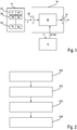
- Fig. 1 shows a device 10 for controlling a machine tool 12.
- Fig. 2 shows a method for controlling the machine tool 12. The method and the device 10 are explained in more detail below.
- Fig. 2 shows a data memory 14 which is used for at least one specific working axis 16, see FIG Fig. 3 , the multiple working axes 16, 17, 18, 19, see Fig. 3 , the machine tool 12 contains a plurality of data tuples D1, D2, ..., Dn. Each of the data tuples D1, D2, ..., Dn assigns a load value B1, B2, ..., Bn to a position value P1, P2, ..., Pn along the specific working axis 16.
- the device 10 has an input interface 20 which is designed to receive at least position data P from the data memory 14.
- the position data P is at least partially the aforementioned position values P1, P2,..., Pn.
- the input interface 20 can receive all position data P from the data memory 14. In certain embodiments, however, only a subset of the position data P is received, in particular, as will be explained below, two position values P1, P2.
- the input interface 20 can also receive at least one load value B1, several load values B1, B2, ..., Bn or all load values B1, B2, ..., Bn.
- the device 10 furthermore has a processing device 22 which is designed to carry out the method according to Fig. 2 , explained below.
- the device 10 also has an output interface 24 which is designed to output at least one item of information I about the wear of a part of the machine tool 12.
- Fig. 2 The procedure according to Fig. 2 is used to control a machine tool 12 with a plurality of working axes 16, 17, 18, 19, which are designed to move a working head 28 and / or a workpiece 30.
- step S10 which contains a plurality of data tuples D1, D2,..., Dn for the at least one specific working axis 16 of the several working axes 16, 17, 18, 19, each of which has a position value P1, P2 , ..., Pn assign a load value B1, B2, ..., Bn along the specific working axis 16.
- a first data tuple D1 having a first position value P1 and a first load value B1
- a second data tuple D2 having a second position value P2 and a second
- the first stress value B1 is different from the second stress value B2.
- At least one control command C is then generated for the machine tool 12, step S14, the control command C being designed to have a first tolerance measurement at a first position described by the first position value P1 and a second tolerance measurement at a second position described by the second position value P2 to be carried out.
- step S16 information I about wear of a part of the machine tool 12 is output on the basis of a first result E1 of the first tolerance measurement and a second result E2 of the second tolerance measurement.
- Fig. 3 shows an embodiment of a machine tool 12 in which a workpiece 30 is clamped.
- the workpiece 30 can be displaced along the working axis 18.
- a working head 28 is also shown, which can be displaced on the one hand by means of the first spindle 26 and also with the second spindle 27.
- the first spindle 26 has the specific working axis 16, and the second spindle 27 has a working axis 19.
- the working head 28 also has a working insert 32 which can be rotated about a working axis 17.
- the first position value P1 and the second position value P2 are also shown symbolically, the corresponding tolerance measurements at the corresponding positions leading to the results E1 and E2.
- the first result E1 of the first tolerance measurement is compared with a first earlier result of a third tolerance measurement at a third position that corresponds to the first position or is close to the first position, in order to obtain a first difference
- the second result E2 of the second tolerance measurement is compared with a second earlier result of a fourth tolerance measurement at a fourth position, which corresponds to the second position or is close to the second position, in order to obtain a second difference.
- the information is output to the effect that wear has taken place on the working head 28, which can be moved along the specific working axis 16.
- the information is output to the effect that wear has taken place on the specific working axis 16, which is spatially invariant in relation to itself. In other words, the specific working axis 16 does not shift relative to itself.
- the first tolerance measurement and the second tolerance measurement are carried out in such a way that a circularity test is carried out, the circular path 32 of which runs through both the first position P1 and the second position P2, see the symbolically indicated circle which indicates the displacement of the working head 28 .
Landscapes
- Engineering & Computer Science (AREA)
- Physics & Mathematics (AREA)
- General Physics & Mathematics (AREA)
- Human Computer Interaction (AREA)
- Manufacturing & Machinery (AREA)
- Automation & Control Theory (AREA)
- Mechanical Engineering (AREA)
- Numerical Control (AREA)
Priority Applications (1)
| Application Number | Priority Date | Filing Date | Title |
|---|---|---|---|
| PL19195711T PL3629116T3 (pl) | 2018-09-17 | 2019-09-05 | Sposób i urządzenie do analizy zużycia obrabiarki |
Applications Claiming Priority (1)
| Application Number | Priority Date | Filing Date | Title |
|---|---|---|---|
| DE102018122759.0A DE102018122759A1 (de) | 2018-09-17 | 2018-09-17 | Verfahren und Vorrichtung für eine Verschleißanalyse an einer Werkzeugmaschine |
Publications (2)
| Publication Number | Publication Date |
|---|---|
| EP3629116A1 EP3629116A1 (de) | 2020-04-01 |
| EP3629116B1 true EP3629116B1 (de) | 2021-05-05 |
Family
ID=67874387
Family Applications (1)
| Application Number | Title | Priority Date | Filing Date |
|---|---|---|---|
| EP19195711.7A Active EP3629116B1 (de) | 2018-09-17 | 2019-09-05 | Verfahren und vorrichtung für eine verschleissanalyse an einer werkzeugmaschine |
Country Status (6)
| Country | Link |
|---|---|
| US (1) | US11340139B2 (es) |
| EP (1) | EP3629116B1 (es) |
| CN (1) | CN110908335B (es) |
| DE (1) | DE102018122759A1 (es) |
| ES (1) | ES2870682T3 (es) |
| PL (1) | PL3629116T3 (es) |
Families Citing this family (2)
| Publication number | Priority date | Publication date | Assignee | Title |
|---|---|---|---|---|
| JP7342444B2 (ja) * | 2019-06-18 | 2023-09-12 | 株式会社ジェイテクト | 加工工具の異常検知装置 |
| DE102020205088A1 (de) | 2020-04-22 | 2021-10-28 | Volkswagen Aktiengesellschaft | Verfahren und Auswertesystem zur Überwachung eines Werkzeugverschleißes von Werkzeugkomponenten bei zerspanenden Fertigungsanlagen |
Family Cites Families (32)
| Publication number | Priority date | Publication date | Assignee | Title |
|---|---|---|---|---|
| US4422150A (en) * | 1980-05-23 | 1983-12-20 | The Boeing Company | Machine tool controller and part inspection monitor |
| DE69314688T2 (de) * | 1992-04-23 | 1998-02-19 | Heidenhain Gmbh Dr Johannes | Numerische Steuerungseinrichtung und Verfahren zur Steuerung der Bewegung eines Werkzeuges |
| JPH09204219A (ja) * | 1996-01-26 | 1997-08-05 | Honda Motor Co Ltd | 加工精度不良発生予防診断方法 |
| US6681145B1 (en) * | 1996-06-06 | 2004-01-20 | The Boeing Company | Method for improving the accuracy of machines |
| DE69916772T2 (de) * | 1998-10-05 | 2005-04-28 | Fanuc Ltd. | Steuervorrichtung eine automatischen Maschine |
| DE60136555D1 (de) * | 2000-10-16 | 2008-12-24 | Makino Milling Machine | Messverfahren und -vorrichtung , mit einer solchenrbeitungsverfahren |
| JP2005040930A (ja) * | 2003-07-25 | 2005-02-17 | Denso Corp | 加工工具の磨耗状況判定方法 |
| DE102005058038B3 (de) | 2005-12-05 | 2007-07-26 | Siemens Ag | Verfahren und Steuereinrichtung zur Bestimmung der Zeitdauer bis zu einer notwendigen Wartung eines Maschinenelementes |
| DE102006006273B4 (de) * | 2006-02-10 | 2014-09-04 | Siemens Aktiengesellschaft | System zur Ermittlung des Verschleißzustandes einer Werkzeugmaschine |
| US20070198123A1 (en) * | 2006-02-23 | 2007-08-23 | Hoffman James J | System and method for measuring machining tools and using data generated therefrom |
| DE102008045470A1 (de) * | 2008-09-03 | 2010-03-04 | Wirtgen Gmbh | Verfahren zur Bestimmung des Verschleißzustandes |
| DE102009025167B3 (de) * | 2009-06-12 | 2010-09-30 | Brinkhaus Gmbh | Verfahren zum Überwachen eines Fertigungsprozesses und Steuerung für eine Werkzeugmaschine |
| CN101804583B (zh) * | 2010-02-22 | 2011-11-09 | 南京航空航天大学 | 基于槽切铣削刀具轮廓复制的磨损测量方法 |
| US8432119B2 (en) * | 2010-04-14 | 2013-04-30 | Babcock & Wilcox Technical Services Y-12, Llc | Method and apparatus for characterizing and enhancing the functional performance of machine tools |
| US8610393B2 (en) * | 2010-04-14 | 2013-12-17 | Babcock & Wilcox Technical Services Y-12, Llc | Method and apparatus for characterizing and enhancing the dynamic performance of machine tools |
| ITBO20120289A1 (it) * | 2012-05-25 | 2013-11-26 | Marposs Spa | Metodo per stimare la velocita' di rotazione di un utensile montato su un mandrino rotante di una macchina utensile |
| KR101343403B1 (ko) * | 2013-08-14 | 2013-12-20 | (주)한국툴모니터링 | 공작기계 운전시의 이상 검출방법 |
| WO2015097893A1 (ja) * | 2013-12-27 | 2015-07-02 | 株式会社牧野フライス製作所 | 工作機械の制御装置 |
| DE102014103240A1 (de) * | 2014-03-11 | 2015-10-01 | Pro-Micron Gmbh & Co. Kg | Verfahren zur Einrichtung und/oder Überwachung von Betriebsparametern einer Werkstückbearbeitungsmaschine |
| AU2016210960B2 (en) * | 2015-01-29 | 2021-05-20 | Zeras S.R.L. | Apparatus and procedure for homing and subsequent positioning of axes of a numerical control machine |
| US10335914B2 (en) * | 2015-02-13 | 2019-07-02 | P + L Gmbh & Co. Kg | Method for determining a position of a work piece in a machine tool |
| JP2016155185A (ja) * | 2015-02-23 | 2016-09-01 | オークマ株式会社 | 工作機械の誤差同定方法 |
| CN105108578A (zh) * | 2015-09-07 | 2015-12-02 | 大连民族大学 | 一种数控车床在线检测和智能补偿刀具磨损装置及方法 |
| DE112016006602T5 (de) * | 2016-03-16 | 2018-12-13 | Mitsubishi Electric Corporation | Maschinenbewegungsbahnverlaufsmessvorrichtung |
| US10585419B1 (en) * | 2016-04-27 | 2020-03-10 | Beneficial Machine Tools Llc | Methods and devices for performing in-situ inspections during a computer assisted setup of a machine tool table |
| JP6599836B2 (ja) * | 2016-09-28 | 2019-10-30 | ファナック株式会社 | 数値制御装置 |
| WO2018154604A1 (en) * | 2017-02-25 | 2018-08-30 | SARUP Siddhant | Method and system for tool life monitoring and management in a cnc environment |
| JP6496338B2 (ja) * | 2017-03-14 | 2019-04-03 | ファナック株式会社 | 工作機械の制御システム |
| JP6514264B2 (ja) * | 2017-04-20 | 2019-05-15 | ファナック株式会社 | 工作機械の制御システム |
| CH714443B1 (de) * | 2017-12-15 | 2020-10-15 | Reishauer Ag | Verfahren und Vorrichtung zur Vermessung eines Wälzbearbeitungswerkzeugs. |
| JP2019207542A (ja) * | 2018-05-29 | 2019-12-05 | ファナック株式会社 | 分析装置、分析方法及び分析プログラム |
| JP2020086514A (ja) * | 2018-11-15 | 2020-06-04 | ファナック株式会社 | パラメータ設定装置、システムおよびパラメータ設定方法 |
-
2018
- 2018-09-17 DE DE102018122759.0A patent/DE102018122759A1/de not_active Withdrawn
-
2019
- 2019-08-13 US US16/539,256 patent/US11340139B2/en active Active
- 2019-09-05 EP EP19195711.7A patent/EP3629116B1/de active Active
- 2019-09-05 ES ES19195711T patent/ES2870682T3/es active Active
- 2019-09-05 PL PL19195711T patent/PL3629116T3/pl unknown
- 2019-09-17 CN CN201910879780.4A patent/CN110908335B/zh active Active
Also Published As
| Publication number | Publication date |
|---|---|
| CN110908335A (zh) | 2020-03-24 |
| US11340139B2 (en) | 2022-05-24 |
| PL3629116T3 (pl) | 2021-11-08 |
| ES2870682T3 (es) | 2021-10-27 |
| US20200088604A1 (en) | 2020-03-19 |
| DE102018122759A1 (de) | 2020-03-19 |
| EP3629116A1 (de) | 2020-04-01 |
| CN110908335B (zh) | 2023-03-21 |
Similar Documents
| Publication | Publication Date | Title |
|---|---|---|
| DE112005000822B4 (de) | Verfahren zur Bearbeitung eines Werkstücks in einer numerisch gesteuerten Drehbank | |
| DE102011006447A1 (de) | Verfahren zum Bearbeiten von Werkstücken mittels einer numerisch gesteuerten Werkstückbearbeitungsvorrichtung sowie Werkstückbearbeitungsvorrichtung | |
| EP3629116B1 (de) | Verfahren und vorrichtung für eine verschleissanalyse an einer werkzeugmaschine | |
| EP0468385A2 (de) | Verfahren zum Umfangsschleifen von radial unrunden Werkstücken | |
| DE19981062B4 (de) | Numerische Steuerung für eine elektro-erosive Bearbeitungsmaschine | |
| EP3636373A1 (de) | Verfahren und vorrichtung zur kontrolle einer stabmessereinspannung und/oder eines messerschachts eines stabmesserkopfs zur kegelradherstellung | |
| DE102008035710A1 (de) | Verfahren zum selbsttätigen Zurückführen eines Werkzeugs einer programmgesteuerten Werkzeugmaschine | |
| DE10241742A1 (de) | Fertigungsanlage zum Herstellen von Produkten | |
| CH715646A2 (de) | Verfahren zur Prüfung einer abrichtbaren Schleifschnecke. | |
| DE102015108851B4 (de) | Verfahren zum Betreiben einer Mehrzahl von Messmaschinen und Gesamtvorrichtung, die mindestens zwei Messmaschinen umfasst | |
| DE102016004185A1 (de) | Numerische Steuerung mit Kontrolle eines Eingriffs zwischen Werkzeug und Werkstück | |
| EP3434413A1 (de) | Vorrichtung zum ermitteln von hochbelasteten positionen bei einer werkzeugmaschine | |
| EP3324170B1 (de) | Verfahren und vorrichtung zur automatisierten bearbeitung und prüfung von zahnrad-bauteilen | |
| EP0534181B1 (de) | Verfahren zur Ermittlung unzulässiger Abweichungen von Verfahrensparametern | |
| DE102020203770A1 (de) | Steuergerät und Werkzeugmaschine | |
| DE102019216972A1 (de) | Verfahren zum Erkennen von Ausschuss bei der Bearbeitung baugleicher Werkstücke sowie zugehörige numerisch gesteuerte Werkstückbearbeitungsvorrichtung | |
| EP3835900A1 (de) | Verfahren und vorrichtung zur prüfung von werkstücken | |
| DE102016214439A1 (de) | Verfahren zur Schruppbearbeitung eines Werkstücks mit einer Mehrachs-Werkzeugmaschine | |
| WO2019086226A1 (de) | Verfahren zum betrieb einer numerisch gesteuerten produktionsanlage sowie produktionsanlage dazu | |
| DE102009039540A1 (de) | Bearbeitungsverfahren | |
| DE10250814B4 (de) | Verfahren zum Vermessen von Werkstücken | |
| DE102019105061A1 (de) | Verfahren zur Vermessung der Oberfläche von Werkstücken | |
| DE102018006652A1 (de) | Verfahren zur Werkzeugkontrolle | |
| EP3848767B1 (de) | Verfahren zur qualitätskontrolle von werkstücken sowie koordinatenmessgerät und computerprogramm | |
| DE19919147B4 (de) | Verfahren zur Ermittlung eines Konturfehlers und Verfahren zur Kontrolle einer korrekten Sollwertvorgabe |
Legal Events
| Date | Code | Title | Description |
|---|---|---|---|
| PUAI | Public reference made under article 153(3) epc to a published international application that has entered the european phase |
Free format text: ORIGINAL CODE: 0009012 |
|
| STAA | Information on the status of an ep patent application or granted ep patent |
Free format text: STATUS: THE APPLICATION HAS BEEN PUBLISHED |
|
| AK | Designated contracting states |
Kind code of ref document: A1 Designated state(s): AL AT BE BG CH CY CZ DE DK EE ES FI FR GB GR HR HU IE IS IT LI LT LU LV MC MK MT NL NO PL PT RO RS SE SI SK SM TR |
|
| AX | Request for extension of the european patent |
Extension state: BA ME |
|
| STAA | Information on the status of an ep patent application or granted ep patent |
Free format text: STATUS: REQUEST FOR EXAMINATION WAS MADE |
|
| 17P | Request for examination filed |
Effective date: 20200416 |
|
| RBV | Designated contracting states (corrected) |
Designated state(s): AL AT BE BG CH CY CZ DE DK EE ES FI FR GB GR HR HU IE IS IT LI LT LU LV MC MK MT NL NO PL PT RO RS SE SI SK SM TR |
|
| GRAJ | Information related to disapproval of communication of intention to grant by the applicant or resumption of examination proceedings by the epo deleted |
Free format text: ORIGINAL CODE: EPIDOSDIGR1 |
|
| STAA | Information on the status of an ep patent application or granted ep patent |
Free format text: STATUS: GRANT OF PATENT IS INTENDED |
|
| GRAP | Despatch of communication of intention to grant a patent |
Free format text: ORIGINAL CODE: EPIDOSNIGR1 |
|
| STAA | Information on the status of an ep patent application or granted ep patent |
Free format text: STATUS: GRANT OF PATENT IS INTENDED |
|
| INTG | Intention to grant announced |
Effective date: 20201214 |
|
| RAP1 | Party data changed (applicant data changed or rights of an application transferred) |
Owner name: CHIRON GROUP SE |
|
| GRAS | Grant fee paid |
Free format text: ORIGINAL CODE: EPIDOSNIGR3 |
|
| GRAA | (expected) grant |
Free format text: ORIGINAL CODE: 0009210 |
|
| STAA | Information on the status of an ep patent application or granted ep patent |
Free format text: STATUS: THE PATENT HAS BEEN GRANTED |
|
| AK | Designated contracting states |
Kind code of ref document: B1 Designated state(s): AL AT BE BG CH CY CZ DE DK EE ES FI FR GB GR HR HU IE IS IT LI LT LU LV MC MK MT NL NO PL PT RO RS SE SI SK SM TR |
|
| REG | Reference to a national code |
Ref country code: GB Ref legal event code: FG4D Free format text: NOT ENGLISH |
|
| REG | Reference to a national code |
Ref country code: CH Ref legal event code: EP Ref country code: CH Ref legal event code: NV Representative=s name: RENTSCH PARTNER AG, CH |
|
| REG | Reference to a national code |
Ref country code: AT Ref legal event code: REF Ref document number: 1390591 Country of ref document: AT Kind code of ref document: T Effective date: 20210515 |
|
| REG | Reference to a national code |
Ref country code: IE Ref legal event code: FG4D Free format text: LANGUAGE OF EP DOCUMENT: GERMAN |
|
| REG | Reference to a national code |
Ref country code: DE Ref legal event code: R096 Ref document number: 502019001363 Country of ref document: DE |
|
| REG | Reference to a national code |
Ref country code: LT Ref legal event code: MG9D |
|
| REG | Reference to a national code |
Ref country code: ES Ref legal event code: FG2A Ref document number: 2870682 Country of ref document: ES Kind code of ref document: T3 Effective date: 20211027 |
|
| PG25 | Lapsed in a contracting state [announced via postgrant information from national office to epo] |
Ref country code: LT Free format text: LAPSE BECAUSE OF FAILURE TO SUBMIT A TRANSLATION OF THE DESCRIPTION OR TO PAY THE FEE WITHIN THE PRESCRIBED TIME-LIMIT Effective date: 20210505 Ref country code: HR Free format text: LAPSE BECAUSE OF FAILURE TO SUBMIT A TRANSLATION OF THE DESCRIPTION OR TO PAY THE FEE WITHIN THE PRESCRIBED TIME-LIMIT Effective date: 20210505 Ref country code: FI Free format text: LAPSE BECAUSE OF FAILURE TO SUBMIT A TRANSLATION OF THE DESCRIPTION OR TO PAY THE FEE WITHIN THE PRESCRIBED TIME-LIMIT Effective date: 20210505 Ref country code: BG Free format text: LAPSE BECAUSE OF FAILURE TO SUBMIT A TRANSLATION OF THE DESCRIPTION OR TO PAY THE FEE WITHIN THE PRESCRIBED TIME-LIMIT Effective date: 20210805 |
|
| PG25 | Lapsed in a contracting state [announced via postgrant information from national office to epo] |
Ref country code: RS Free format text: LAPSE BECAUSE OF FAILURE TO SUBMIT A TRANSLATION OF THE DESCRIPTION OR TO PAY THE FEE WITHIN THE PRESCRIBED TIME-LIMIT Effective date: 20210505 Ref country code: SE Free format text: LAPSE BECAUSE OF FAILURE TO SUBMIT A TRANSLATION OF THE DESCRIPTION OR TO PAY THE FEE WITHIN THE PRESCRIBED TIME-LIMIT Effective date: 20210505 Ref country code: PT Free format text: LAPSE BECAUSE OF FAILURE TO SUBMIT A TRANSLATION OF THE DESCRIPTION OR TO PAY THE FEE WITHIN THE PRESCRIBED TIME-LIMIT Effective date: 20210906 Ref country code: NO Free format text: LAPSE BECAUSE OF FAILURE TO SUBMIT A TRANSLATION OF THE DESCRIPTION OR TO PAY THE FEE WITHIN THE PRESCRIBED TIME-LIMIT Effective date: 20210805 Ref country code: LV Free format text: LAPSE BECAUSE OF FAILURE TO SUBMIT A TRANSLATION OF THE DESCRIPTION OR TO PAY THE FEE WITHIN THE PRESCRIBED TIME-LIMIT Effective date: 20210505 Ref country code: IS Free format text: LAPSE BECAUSE OF FAILURE TO SUBMIT A TRANSLATION OF THE DESCRIPTION OR TO PAY THE FEE WITHIN THE PRESCRIBED TIME-LIMIT Effective date: 20210905 Ref country code: GR Free format text: LAPSE BECAUSE OF FAILURE TO SUBMIT A TRANSLATION OF THE DESCRIPTION OR TO PAY THE FEE WITHIN THE PRESCRIBED TIME-LIMIT Effective date: 20210806 |
|
| REG | Reference to a national code |
Ref country code: NL Ref legal event code: MP Effective date: 20210505 |
|
| PG25 | Lapsed in a contracting state [announced via postgrant information from national office to epo] |
Ref country code: NL Free format text: LAPSE BECAUSE OF FAILURE TO SUBMIT A TRANSLATION OF THE DESCRIPTION OR TO PAY THE FEE WITHIN THE PRESCRIBED TIME-LIMIT Effective date: 20210505 |
|
| PG25 | Lapsed in a contracting state [announced via postgrant information from national office to epo] |
Ref country code: EE Free format text: LAPSE BECAUSE OF FAILURE TO SUBMIT A TRANSLATION OF THE DESCRIPTION OR TO PAY THE FEE WITHIN THE PRESCRIBED TIME-LIMIT Effective date: 20210505 Ref country code: SK Free format text: LAPSE BECAUSE OF FAILURE TO SUBMIT A TRANSLATION OF THE DESCRIPTION OR TO PAY THE FEE WITHIN THE PRESCRIBED TIME-LIMIT Effective date: 20210505 Ref country code: RO Free format text: LAPSE BECAUSE OF FAILURE TO SUBMIT A TRANSLATION OF THE DESCRIPTION OR TO PAY THE FEE WITHIN THE PRESCRIBED TIME-LIMIT Effective date: 20210505 Ref country code: SM Free format text: LAPSE BECAUSE OF FAILURE TO SUBMIT A TRANSLATION OF THE DESCRIPTION OR TO PAY THE FEE WITHIN THE PRESCRIBED TIME-LIMIT Effective date: 20210505 Ref country code: CZ Free format text: LAPSE BECAUSE OF FAILURE TO SUBMIT A TRANSLATION OF THE DESCRIPTION OR TO PAY THE FEE WITHIN THE PRESCRIBED TIME-LIMIT Effective date: 20210505 Ref country code: DK Free format text: LAPSE BECAUSE OF FAILURE TO SUBMIT A TRANSLATION OF THE DESCRIPTION OR TO PAY THE FEE WITHIN THE PRESCRIBED TIME-LIMIT Effective date: 20210505 |
|
| REG | Reference to a national code |
Ref country code: DE Ref legal event code: R097 Ref document number: 502019001363 Country of ref document: DE |
|
| PLBE | No opposition filed within time limit |
Free format text: ORIGINAL CODE: 0009261 |
|
| STAA | Information on the status of an ep patent application or granted ep patent |
Free format text: STATUS: NO OPPOSITION FILED WITHIN TIME LIMIT |
|
| 26N | No opposition filed |
Effective date: 20220208 |
|
| REG | Reference to a national code |
Ref country code: BE Ref legal event code: MM Effective date: 20210930 |
|
| PG25 | Lapsed in a contracting state [announced via postgrant information from national office to epo] |
Ref country code: IS Free format text: LAPSE BECAUSE OF FAILURE TO SUBMIT A TRANSLATION OF THE DESCRIPTION OR TO PAY THE FEE WITHIN THE PRESCRIBED TIME-LIMIT Effective date: 20210905 Ref country code: MC Free format text: LAPSE BECAUSE OF FAILURE TO SUBMIT A TRANSLATION OF THE DESCRIPTION OR TO PAY THE FEE WITHIN THE PRESCRIBED TIME-LIMIT Effective date: 20210505 Ref country code: AL Free format text: LAPSE BECAUSE OF FAILURE TO SUBMIT A TRANSLATION OF THE DESCRIPTION OR TO PAY THE FEE WITHIN THE PRESCRIBED TIME-LIMIT Effective date: 20210505 |
|
| PG25 | Lapsed in a contracting state [announced via postgrant information from national office to epo] |
Ref country code: LU Free format text: LAPSE BECAUSE OF NON-PAYMENT OF DUE FEES Effective date: 20210905 Ref country code: IE Free format text: LAPSE BECAUSE OF NON-PAYMENT OF DUE FEES Effective date: 20210905 Ref country code: FR Free format text: LAPSE BECAUSE OF NON-PAYMENT OF DUE FEES Effective date: 20210930 Ref country code: BE Free format text: LAPSE BECAUSE OF NON-PAYMENT OF DUE FEES Effective date: 20210930 |
|
| PG25 | Lapsed in a contracting state [announced via postgrant information from national office to epo] |
Ref country code: CY Free format text: LAPSE BECAUSE OF FAILURE TO SUBMIT A TRANSLATION OF THE DESCRIPTION OR TO PAY THE FEE WITHIN THE PRESCRIBED TIME-LIMIT Effective date: 20210505 |
|
| PG25 | Lapsed in a contracting state [announced via postgrant information from national office to epo] |
Ref country code: HU Free format text: LAPSE BECAUSE OF FAILURE TO SUBMIT A TRANSLATION OF THE DESCRIPTION OR TO PAY THE FEE WITHIN THE PRESCRIBED TIME-LIMIT; INVALID AB INITIO Effective date: 20190905 |
|
| PGFP | Annual fee paid to national office [announced via postgrant information from national office to epo] |
Ref country code: PL Payment date: 20230824 Year of fee payment: 5 |
|
| PGFP | Annual fee paid to national office [announced via postgrant information from national office to epo] |
Ref country code: ES Payment date: 20231124 Year of fee payment: 5 |
|
| PGFP | Annual fee paid to national office [announced via postgrant information from national office to epo] |
Ref country code: IT Payment date: 20230927 Year of fee payment: 5 Ref country code: DE Payment date: 20231027 Year of fee payment: 5 Ref country code: CH Payment date: 20231001 Year of fee payment: 5 |
|
| PG25 | Lapsed in a contracting state [announced via postgrant information from national office to epo] |
Ref country code: MK Free format text: LAPSE BECAUSE OF FAILURE TO SUBMIT A TRANSLATION OF THE DESCRIPTION OR TO PAY THE FEE WITHIN THE PRESCRIBED TIME-LIMIT Effective date: 20210505 |
|
| GBPC | Gb: european patent ceased through non-payment of renewal fee |
Effective date: 20230905 |
|
| PG25 | Lapsed in a contracting state [announced via postgrant information from national office to epo] |
Ref country code: GB Free format text: LAPSE BECAUSE OF NON-PAYMENT OF DUE FEES Effective date: 20230905 |
|
| PG25 | Lapsed in a contracting state [announced via postgrant information from national office to epo] |
Ref country code: GB Free format text: LAPSE BECAUSE OF NON-PAYMENT OF DUE FEES Effective date: 20230905 |