EP3628384B1 - Achterbahn - Google Patents
Achterbahn Download PDFInfo
- Publication number
- EP3628384B1 EP3628384B1 EP19181212.2A EP19181212A EP3628384B1 EP 3628384 B1 EP3628384 B1 EP 3628384B1 EP 19181212 A EP19181212 A EP 19181212A EP 3628384 B1 EP3628384 B1 EP 3628384B1
- Authority
- EP
- European Patent Office
- Prior art keywords
- reception means
- passenger
- foot support
- passenger reception
- shaped
- Prior art date
- Legal status (The legal status is an assumption and is not a legal conclusion. Google has not performed a legal analysis and makes no representation as to the accuracy of the status listed.)
- Active
Links
Images


Classifications
-
- A—HUMAN NECESSITIES
- A63—SPORTS; GAMES; AMUSEMENTS
- A63G—MERRY-GO-ROUNDS; SWINGS; ROCKING-HORSES; CHUTES; SWITCHBACKS; SIMILAR DEVICES FOR PUBLIC AMUSEMENT
- A63G7/00—Up-and-down hill tracks; Switchbacks
Definitions
- the invention relates to a roller coaster according to the features of claim 1.
- Rail-guided rides are well known as roller coasters and are enjoying increasing popularity due to the joy of driving among passengers.
- a rail-guided ride is off EP 2 298 426 B1 or US5791254 known.
- This amusement ride provides a vehicle with multiple passenger receptacles for passengers.
- the vehicle has one or more rows of passenger receptacles, the two middle passenger receptacles being designed with a footrest in the form of a floor panel.
- This floor plate serves, on the one hand, to cover the rails and, on the other hand, to comfortably rest the feet of the passengers.
- the two seats to the left and right of the middle passenger seats are equipped without such a footrest in order to give the passengers seated on these outer passenger seats the illusion of a freely floating journey.
- the illusion is conveyed in particular because the passengers seated in the outer passenger seats drive "floorless", ie can look down freely, and can also let their feet hang freely because a footrest is missing.
- roller coaster In addition to this rail-guided ride with two differently designed passenger seats, where the passengers sitting outside can let their feet dangle freely during the roller coaster ride, similar rides have already become known under the name "Wing Coaster”. With these roller coasters, also called “wing roller coaster”, the passengers sit in their passenger seats on the left and right laterally next to the rail, whereby the passengers are not impaired in terms of view either downwards by footrests or upwards by any superstructures of the ride The illusion of free flying while driving on such roller coasters can thus be well simulated.
- the aim of the invention is to provide a roller coaster in which passenger shots with different driving sensations are offered on one and the same roller coaster, with passenger shots will be ready, in which the feeling of a free-floating ride is enhanced, but safety aspects are still met.
- the solution according to the invention is essentially based on the fact that the passengers of a roller coaster, with one and the same roller coaster, a vehicle with several passenger receptacles is made available, with the passenger on a first passenger receptacle, such as a vehicle seat, a completely different driving experience than on one second passenger receptacle, such as a passenger seat placed next door, can feel.
- the first passenger seats are preferably located above the course of the rails and have a flat and preferably non-transparent footrest, such as a footplate. The passengers who take a seat in these first passenger seats have a high feeling of security on these first passenger seats because they can support their feet over the entire surface on the large footrest.
- this feeling of security is enhanced by the fact that using the flat footplate avoids looking down, so anxious people who are sensitive to height, for example, always have the feeling that they have a floor under their feet.
- the flat footrest shields the feet of those recorded in the first passenger recordings Safely remove people from the rails, so that there is no risk of the passengers getting their feet between the rails.
- this flat footrest can be stepped on by passengers when getting in and out of the assigned passenger receptacles.
- the second passenger receptacles are not provided with such a flat footrest, but with a rod-shaped footrest so that the view down is largely free and the passengers who have taken their seats in the second passenger receptacles can look down almost unhindered. Nevertheless, these passengers can safely support their feet on the rod-shaped footrest, if this is desired by the passengers, so that in this respect an increased feeling of security is achieved for the passengers. In addition, those passengers who may be wearing loose shoes, for example sandals or flip-flops or the like, can safely support their feet and thus also the shoes on the bar-shaped footrests, so that these shoes can be avoided inadvertently falling off.
- rod-shaped footrests can also be used as a step aid when the passengers get on and off the second passenger receptacles. This is particularly beneficial for smaller people when the vehicle drives into a train station and the passengers get in or out of their vehicle seat in a simple manner by stepping on the slightly higher rod-shaped footrest.
- the rod-shaped footrest is preferably used for passenger receptacles in rail-guided rides with differently designed passenger receptacles, it is also within the scope of the invention that the rod-shaped Foot mount is also used in roller coasters that only have the same passenger mounts.
- roller coasters examples of such roller coasters are the roller coasters mentioned at the beginning as "wing coaster".
- the passenger seats are only placed to the side of the rails, i.e. to the left and right of the rails.
- the passenger names are all identical or almost identical and so far have no footrests at all.
- all or only some of the passenger seats of “wing coasters” can also be provided with rod-shaped footrests in order to increase the feeling of security of the passengers accommodated therein.
- the rod-shaped footrests are U-shaped or at least approximately U-shaped.
- the two free ends of such a U-leg are preferably fixed to a seat substructure of the passenger accommodation, for example by means of screws.
- Such a U-leg-shaped design of the rod-shaped footrest is characterized by high mechanical stability compared to such rod-shaped footrests which are L-shaped and are only mounted on one leg on the floor-side construction of a passenger seat.
- the rod-shaped footrests are preferably releasably attached to the passenger seat.
- This has the advantage that passenger seats can also be provided on which no footrests are mounted at all, so that there is the possibility of a roller coaster with three differently designed
- passenger receptacles a first passenger receptacle with a flat, preferably non-transparent footrest, a second passenger receptacle with a rod-shaped footrest and a third passenger receptacle without any footrest.
- the rod-shaped footrests can also be arranged in a foldable and / or pivotable manner on the respective second passenger seats.
- Such a foldable or pivotable arrangement of the rod-shaped footrests has the advantage that a passenger can decide at will whether he wants to use the rod-shaped footrest when riding the roller coaster or not.
- the rod-shaped footrests are expediently designed in such a way that you cannot slip on them when you place your feet on the rod-shaped footrests. This can be achieved, for example, in that an anti-slip covering, such as a rubber covering, is applied at least in sections to the rod-shaped footrests. Other measures, such as roughening the surface of the rod-shaped footrest, are also possible.
- the distance between the rod-shaped footrest or the area attached to the rod-shaped footrest, on which passengers can support their feet is exactly the same or at least approximately equal to the distance between the flat footrest and the seat belonging to the flat footrest Has.
- This measure has the decisive advantage that passengers who, for reasons of uncertainty, first take a seat on the first passenger seat with the corresponding flat footrest and support their feet on such a roller coaster, on the next trip on the second, which is preferably on the outside Change passenger seats and can support their feet in a similar way, which gives them an increased feeling of security compared to hanging their feet freely and still - almost - the feeling of a free-floating journey, because the view down is released thanks to the omission of a flat footrest .
- the second passenger receptacles with the rod-shaped footrests are placed higher than the first passenger receptacles to which the flat footrest is assigned compared to the level of the rails.
- These second passenger seats with the rod-shaped footrests are preferably also located laterally offset from the first passenger seats.
- the roller coaster can have a train station with platforms that extend right up to the flat footrest of the first passenger seats.
- the second passenger receptacles are located above the platforms when vehicles have entered the station, so that the passengers seated there can easily get in and out of these passenger receptacles.
- the rod-shaped footrests serve as a step aid for passengers to get on and off.
- the rod-shaped footrests of the second passenger seats are placed above (e.g. at a distance of about 20 cm or more) from the platform, so that when the vehicle drives into the station there is always a collision of the outer passenger seats or the feet inside passengers located on the platform can be safely avoided.
- At least one second row of seats is provided.
- the respective seating direction of the passenger seats in the second row of seats can be in or against the direction of travel of the vehicle.
- the passenger receptacles in the second row of seats can also have rod-shaped or further footrests, which are preferably offset backwards in the seating direction and can be arranged under the seat surface within the projection of the seat surface.
- the at least one second row of seats can be designed analogously to the at least one first row of seats.
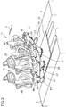
- FIG 1 a first embodiment of a vehicle 10 of a roller coaster is shown.
- the vehicle 10 has a vehicle chassis 10a, on the upper side of which a total of several passenger receptacles 20, 40 are placed.
- These passenger seats 20, 40 are divided into two rows of seats, namely a first row of seats 11 and a second row of seats 12, so that four passenger seats 20, 40 are arranged next to one another in each row of seats.
- Each passenger receptacle 20, 40 has a seating direction in which a passenger who has been seated on the passenger receptacle 20, 40 as intended, looks.
- Wheels 13 are mounted on the underside of the chassis 10a, with which the vehicle 10 can move on the rails of the roller coaster.
- the various passenger seats 20, 40 are equipped with footrests 22, 42 in a special way.
- Each of the first passenger seats 20 has seats with a seat surface 28 and a front seat edge 27.
- the seat surfaces 28 of these first passenger seats 20 are inclined slightly backwards - in relation to the direction of travel F of the vehicle 10 - and the seat direction is aligned in the direction of travel F.
- the distance between the front seat edge 27 of this first passenger seat 20 and the flat footrest 22 is as shown in FIG Figure 3 recognizable, denoted by the reference character A.
- This distance A can be between 40 and 50 cm, for example, and vary as required depending on the roller coaster. It is only important that the majority of people riding the roller coaster can actually use the flat footrest 22 to support their feet. As in particular from the Figures 2 and 3 As can be seen, the flat footrest 22 clearly protrudes in the direction of travel F or seat direction over the front seat edge 27 of the first passenger seat 20. How beyond Figure 2 shows, the flat footrest 22 is a common flat footrest 22 for the two middle passenger seats 20. In a similar way, the two middle first passenger seats 20 provided there in the second row 12 are equipped with a similar flat footrest 22.
- the outer passenger receptacles 40 which are referred to below as second passenger receptacles 40, have one Completely differently designed footrest 42.
- the footrests 42 provided there and assigned to the respective second passenger receptacle 40 are designed as rod-shaped footrests 42.
- this rod-shaped footrest 42 is U-shaped and preferably detachable with its distal ends of the respective two U-legs on the seat frame 44, e.g. B. by means of screws.
- the detachable fastening has the decisive advantage that, depending on requirements, the rod-shaped footrests 42 can be screwed tightly to the respective second passenger receptacles 40 or not.
- This rod-shaped and preferably U-shaped footrest 42 is fastened in the rear area at the bottom of the seat frame 44 and bent forward in an L-shape in the direction of travel F or seat direction in a side view so that passengers who are accommodated in the second passenger receptacle 40 with their Find a secure support for your feet on these footrests.
- the front end of the rod-shaped footrest 42 does not protrude beyond the front seat edge 27 in the sitting direction.
- This measure and the rod-shaped design of the footrest 42 ensure that a passenger accommodated in the second passenger receptacle 40 is in no way hindered from looking down, so that the feeling of a freely floating journey can be conveyed.
- the passenger accommodated in the second passenger receptacle 40 is free at any time to dangle his legs freely if he does not want to support himself with his feet on the rod-shaped footrest 42. This can also further increase the illusion of a free-floating ride.
- the bar-shaped footrest 42 offers an ideal opportunity to physically to be able to support with his feet. This support is particularly helpful if the passenger accommodated in the second passenger receptacle 40 is wearing loose shoes, such as. B. wearing sandals or flip-flops. Supporting your feet ensures that you don't accidentally lose your footwear on a roller coaster ride.
- This section is in Figure 2 provided with the reference number 43.
- a section which is provided for supporting the feet on the rod-shaped footrest 42 is provided with an anti-slip coating, e.g. B. a rubber-like coating or a roughening of the rod-shaped footrest 42 is provided.
- an anti-slip coating e.g. B. a rubber-like coating or a roughening of the rod-shaped footrest 42 is provided.
- the distance B between the front seat edge 47 and the front area of the bar-shaped footrest 42, on which a passenger can support himself with his feet is just as large or preferably as large as the distance A between the front seat edge 27 and the flat Footrest 22 of the first passenger seat 20.
- the rod-shaped footrests 42 are located within a projection 65 of the seat surface 48 of the second passenger receptacle 40, that is to say do not extend beyond the projected seat surface 48.
- This projected seat is in Figure 3 denoted by the reference numeral 65. This ensures that the rod-shaped footrest 42 is in any case located below the seat surface and does not extend beyond it and thus the view of a passenger sitting in the second passenger receptacle 40 is not obstructed.
- the rod-shaped footrest 42 can also protrude forward over the seat edge 47 in the direction of travel F in order to enable the passengers to support their feet even if they do not want to bend their legs and feet backwards to avoid the Support feet on the footrest 42.
- Such a footrest 42, which is extended in the direction of travel F, is shown in FIG Figure 3 indicated by a dashed extension of the rod-shaped footrest 42 in the direction of travel F.
- FIG 4 a row of seats 11 is shown which largely corresponds to the first exemplary embodiment shown above.
- the rod-shaped footrest 42 presented there is made significantly shorter in the direction of travel F or in the seat direction, so that the front area of the flat footrest 42 does not protrude over the seat surface 48 and in particular not over the front seat edge 47 of the second passenger receptacle 40.
- the rod-shaped footrest 42 which also in this embodiment of Figure 4 Rather, it is located within a projection surface of the seat 28 of the second passenger seat 40.
- the main advantage of such a shortened, rod-shaped footrest 42 is that a passenger seated in the second passenger seat 40 does not look down at all is hindered by any structures. The feeling of a free-floating ride is thus optimally fulfilled for the respective passenger, at least visually.
- Figure 5 shows a third embodiment of passenger seats 20, 40 of a first row of seats 11 of a roller coaster.
- the embodiment of Figure 5 largely resembles the previously illustrated embodiments, the rod-shaped Footrest 42 is now not U-shaped, but merely as a straight bolt protruding from the seat frame left and right orthogonally to the direction of travel F and extending straight away. These bolts are in turn arranged in such a way that they do not protrude beyond a projection 65 of the seat surface 48 of the second passenger receptacle 40.
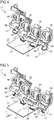
- Figure 6 shows a fourth embodiment, which differs from the aforementioned embodiments of passenger seats in two points.
- another passenger receptacle 60 on the underside of which there is another footrest 62, which is not rod-shaped, but now plate-shaped and has a central opening 63.
- the further footrest 62 is designed such that it is in turn arranged below the seat surface of the further passenger receptacle 60 and does not protrude beyond the outer edge of the seat.
- the projection of the seat of the further foot receptacle 60 is in Figure 6 again denoted by the reference number 65.
- the further footrest 62 is exclusively the one in Figure 6 further foot receptacle 60 shown on the right is assigned.
- This further footrest 62 is used exclusively for a passenger who has taken a seat in the further passenger receptacle 60.
- the flat footrest 22 is used for two passengers who can be accommodated in the two middle passenger receptacles 20.
- a further passenger receptacle 70 can be seen on the far left, which has no footrest at all. This row of seats, as shown in Figure 6 is shown, passenger receptacles 20, 60 and 70, for three different driving sensations.
- Figure 7 shows a fifth embodiment. This embodiment differs from the embodiment of FIG Figure 6 because the in Figure 7
- the footrest 67 shown is designed in the form of a plate, but has no central opening.
- the two platforms 3 protrude under the two outer, ie second passenger receptacles 40. Therefore, the passengers who want to take a seat on these second passenger receptacles 40 regularly only need to stand on the platforms 3 and from there can go directly to the second passenger receptacles 40 enter. Since in the illustrated embodiment the two outer, that is to say second, passenger receptacles 40 are placed slightly higher, like the first two passenger seats 20 located in the middle, the rod-shaped footrests 42 advantageously serve as a boarding aid, in that the passengers step on these rod-shaped footrests 42 to climb the second passenger seats 40, the more easily into the seats 48 of the second Ascend passenger seats 40 and take a seat there. This is of great advantage especially for smaller people.
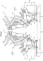
- Figure 8 shows a roller coaster with at least two rows of seats 11, 12.
- the respective seat direction of the second row of seats 12 is not oriented in the direction of travel F of the vehicle 10, but rather the direction of the passenger seats 20, 40 of the second row of seats 12 aligned against the direction of travel F.
- the passengers in or on the first and second passenger receptacles 20, 40 in the second row of seats 12 thus drive backwards and look backwards as intended.
- the first passenger seats 20 of the second row of seats 12 have a common flat footrest 22, which, in contrast to the flat footrest 22 of the first row of seats 12, is now opposite to the direction of travel F of the vehicle 10 - but still in the seating direction as in the previously introduced embodiments - projects well beyond the front seat edges 27 of the first passenger receptacles 20.
- the second passenger seats 40 also have footrests 42 which can be designed analogously to the rod-shaped or further footrests 42 or 62 discussed above.
- the rod-shaped footrests 42 or the further footrests 62 of the second row of seats 12 are preferably - as shown - arranged within a projection 65 of the seat surface 48 of the second passenger receptacle 40, that is, do not extend beyond the projected seat surface 48, whereby the footrests 42, 62 for the passenger on the second passenger receptacle 40 cannot be seen during the ride of the roller coaster and the feeling of a free-floating ride is enhanced, but safety aspects are still met.
- the rod-shaped footrest 42 but also the further footrest 62 (not shown) in the second row of seats 12 accordingly do not protrude in the seat direction beyond the front seat edge 47 of the second passenger receptacle 40.
- the second passenger receptacles 40 in the second row of seats 12 can be offset forwards or backwards in the direction of travel F or, as seen in the seat direction, analogously to the exemplary embodiment described above.
- the seat row 11 and the second seat row 12 are arranged mirror-symmetrically.
- the second passenger receptacles 40 can also be placed higher than the first passenger receptacles 20 in the second row of seats 12 relative to the level of the rails.
Landscapes
- Passenger Equipment (AREA)
Applications Claiming Priority (1)
| Application Number | Priority Date | Filing Date | Title |
|---|---|---|---|
| DE102018123640.9A DE102018123640B3 (de) | 2018-09-25 | 2018-09-25 | Achterbahn |
Publications (2)
| Publication Number | Publication Date |
|---|---|
| EP3628384A1 EP3628384A1 (de) | 2020-04-01 |
| EP3628384B1 true EP3628384B1 (de) | 2020-11-18 |
Family
ID=66999577
Family Applications (1)
| Application Number | Title | Priority Date | Filing Date |
|---|---|---|---|
| EP19181212.2A Active EP3628384B1 (de) | 2018-09-25 | 2019-06-19 | Achterbahn |
Country Status (5)
| Country | Link |
|---|---|
| EP (1) | EP3628384B1 (da) |
| DE (1) | DE102018123640B3 (da) |
| DK (1) | DK3628384T3 (da) |
| ES (1) | ES2838005T3 (da) |
| HU (1) | HUE052534T2 (da) |
Family Cites Families (9)
| Publication number | Priority date | Publication date | Assignee | Title |
|---|---|---|---|---|
| US5791254A (en) * | 1995-11-03 | 1998-08-11 | Meteoro Amusement Corporation | Full range of motion roller coaster |
| NL1007411C2 (nl) | 1997-10-31 | 1999-05-04 | Vekoma Tech Bv | Amusementsinrichtingen alsmede houder geschikt voor dergelijke amusementsinrichtingen. |
| ATE317782T1 (de) * | 2000-12-13 | 2006-03-15 | Bolliger & Mabillard | Vorrichtung zum festhalten der beine eines insassen in einem sitz |
| EP1904204A1 (en) | 2005-05-20 | 2008-04-02 | William J. Kitchen | Wheel hub rider conveyance |
| WO2007136245A1 (en) * | 2006-05-24 | 2007-11-29 | Vekoma Rides Engineering B.V. | Amusement ride device |
| DE202007001485U1 (de) * | 2007-01-26 | 2007-03-29 | Zierer Karussell- Und Spezialmaschinenbau Gmbh | Fahrgastrückhaltevorrichtung für Fahrgeschäfte |
| DE102009044065A1 (de) | 2009-09-21 | 2011-03-24 | Maurer Söhne Gmbh & Co. Kg | Fahrgeschäft mit unterschiedlichen Sitzvarianten |
| US8943976B2 (en) * | 2012-12-17 | 2015-02-03 | Disney Enterprises, Inc. | Flying roller coaster with vertical load and launch |
| NL2018934B1 (en) * | 2017-05-17 | 2018-11-28 | Vekoma Rides Eng B V | Amusement device seat assembly including leg locking device. |
-
2018
- 2018-09-25 DE DE102018123640.9A patent/DE102018123640B3/de not_active Expired - Fee Related
-
2019
- 2019-06-19 HU HUE19181212A patent/HUE052534T2/hu unknown
- 2019-06-19 ES ES19181212T patent/ES2838005T3/es active Active
- 2019-06-19 EP EP19181212.2A patent/EP3628384B1/de active Active
- 2019-06-19 DK DK19181212.2T patent/DK3628384T3/da active
Non-Patent Citations (1)
| Title |
|---|
| None * |
Also Published As
| Publication number | Publication date |
|---|---|
| DE102018123640B3 (de) | 2019-12-12 |
| DK3628384T3 (da) | 2021-02-01 |
| EP3628384A1 (de) | 2020-04-01 |
| HUE052534T2 (hu) | 2021-05-28 |
| ES2838005T3 (es) | 2021-07-01 |
Similar Documents
| Publication | Publication Date | Title |
|---|---|---|
| DE69203701T2 (de) | Vergnügungsbahn nach Art einer Achterbahn. | |
| DE69916003T2 (de) | Anlage für Vergnügungspark, genannt Achterbahn | |
| DE102010054942A1 (de) | Raumoptimierter Flugbegleiter-Stehsitz für Luftfahrzeuge | |
| DE60133610T2 (de) | Anlage für Vergnügungspark, genannt Achterbahn | |
| DE2424134A1 (de) | Sitzmoebel | |
| EP3628384B1 (de) | Achterbahn | |
| DE7615171U1 (de) | Sitzgelegenheit | |
| DE7002318U (de) | Schneegleitgeraet | |
| EP2298426B1 (de) | Fahrgeschäft mit unterschiedlichen Sitzvarianten | |
| DE102009047516B4 (de) | Schienensystem sowie ein Fahrbrett für das Schienensystem | |
| DE864739C (de) | Frei stehender Stuhl fuer Schulzwecke u. dgl. | |
| DE4016687A1 (de) | Sitzanordnung in fahrzeugen, insbesondere personenkraftfahrzeugen | |
| DE102011017257B4 (de) | Eindecker-Omnibusfahrzeug | |
| DE102019123436A1 (de) | Gehhilfe, Rollator oder dergleichen | |
| DE102010018910A1 (de) | Fußstützeinrichtung | |
| DE3817111A1 (de) | Schienenlastfahrzeugaufbau | |
| DE102018215374B4 (de) | Fußauflage für ein Fahrzeug und Fahrzeugsitzanordnung | |
| DE202023101809U1 (de) | Sitz- und Stehmöbel zur Unterstützung der Bewegung einer Person mit Muskelhypotonie, Ataxie und/oder spastischer Cerebralparese | |
| DE9205263U1 (de) | Wagen zum Transport von Personen | |
| DE3330371C2 (da) | ||
| DE8405231U1 (de) | Gerät zum Erlernen des Schlittschuh- oder Rollschuhlaufens | |
| DE29902886U1 (de) | Vorrichtung für den Wohnbereich zur Befestigung und/oder Anordnung von Modul-Steuerhilfen | |
| DE202016007181U1 (de) | Kugelbahn | |
| DE3832939A1 (de) | Kinderfahrzeug/kindersitz-kombination | |
| DE9306780U1 (de) | Sitz-Schaukel |
Legal Events
| Date | Code | Title | Description |
|---|---|---|---|
| PUAI | Public reference made under article 153(3) epc to a published international application that has entered the european phase |
Free format text: ORIGINAL CODE: 0009012 |
|
| STAA | Information on the status of an ep patent application or granted ep patent |
Free format text: STATUS: REQUEST FOR EXAMINATION WAS MADE |
|
| 17P | Request for examination filed |
Effective date: 20191217 |
|
| AK | Designated contracting states |
Kind code of ref document: A1 Designated state(s): AL AT BE BG CH CY CZ DE DK EE ES FI FR GB GR HR HU IE IS IT LI LT LU LV MC MK MT NL NO PL PT RO RS SE SI SK SM TR |
|
| AX | Request for extension of the european patent |
Extension state: BA ME |
|
| RIN1 | Information on inventor provided before grant (corrected) |
Inventor name: SORNIK, FRANK Inventor name: SIMON, CHRISTIAN |
|
| GRAP | Despatch of communication of intention to grant a patent |
Free format text: ORIGINAL CODE: EPIDOSNIGR1 |
|
| STAA | Information on the status of an ep patent application or granted ep patent |
Free format text: STATUS: GRANT OF PATENT IS INTENDED |
|
| INTG | Intention to grant announced |
Effective date: 20200630 |
|
| GRAS | Grant fee paid |
Free format text: ORIGINAL CODE: EPIDOSNIGR3 |
|
| GRAA | (expected) grant |
Free format text: ORIGINAL CODE: 0009210 |
|
| STAA | Information on the status of an ep patent application or granted ep patent |
Free format text: STATUS: THE PATENT HAS BEEN GRANTED |
|
| AK | Designated contracting states |
Kind code of ref document: B1 Designated state(s): AL AT BE BG CH CY CZ DE DK EE ES FI FR GB GR HR HU IE IS IT LI LT LU LV MC MK MT NL NO PL PT RO RS SE SI SK SM TR |
|
| REG | Reference to a national code |
Ref country code: GB Ref legal event code: FG4D Free format text: NOT ENGLISH |
|
| REG | Reference to a national code |
Ref country code: CH Ref legal event code: EP |
|
| REG | Reference to a national code |
Ref country code: IE Ref legal event code: FG4D Free format text: LANGUAGE OF EP DOCUMENT: GERMAN |
|
| REG | Reference to a national code |
Ref country code: DE Ref legal event code: R096 Ref document number: 502019000419 Country of ref document: DE |
|
| REG | Reference to a national code |
Ref country code: AT Ref legal event code: REF Ref document number: 1335104 Country of ref document: AT Kind code of ref document: T Effective date: 20201215 Ref country code: RO Ref legal event code: EPE |
|
| REG | Reference to a national code |
Ref country code: DK Ref legal event code: T3 Effective date: 20210125 |
|
| REG | Reference to a national code |
Ref country code: SE Ref legal event code: TRGR |
|
| REG | Reference to a national code |
Ref country code: NL Ref legal event code: FP |
|
| REG | Reference to a national code |
Ref country code: SK Ref legal event code: T3 Ref document number: E 36253 Country of ref document: SK |
|
| PG25 | Lapsed in a contracting state [announced via postgrant information from national office to epo] |
Ref country code: FI Free format text: LAPSE BECAUSE OF FAILURE TO SUBMIT A TRANSLATION OF THE DESCRIPTION OR TO PAY THE FEE WITHIN THE PRESCRIBED TIME-LIMIT Effective date: 20201118 Ref country code: RS Free format text: LAPSE BECAUSE OF FAILURE TO SUBMIT A TRANSLATION OF THE DESCRIPTION OR TO PAY THE FEE WITHIN THE PRESCRIBED TIME-LIMIT Effective date: 20201118 Ref country code: PT Free format text: LAPSE BECAUSE OF FAILURE TO SUBMIT A TRANSLATION OF THE DESCRIPTION OR TO PAY THE FEE WITHIN THE PRESCRIBED TIME-LIMIT Effective date: 20210318 Ref country code: NO Free format text: LAPSE BECAUSE OF FAILURE TO SUBMIT A TRANSLATION OF THE DESCRIPTION OR TO PAY THE FEE WITHIN THE PRESCRIBED TIME-LIMIT Effective date: 20210218 Ref country code: GR Free format text: LAPSE BECAUSE OF FAILURE TO SUBMIT A TRANSLATION OF THE DESCRIPTION OR TO PAY THE FEE WITHIN THE PRESCRIBED TIME-LIMIT Effective date: 20210219 |
|
| REG | Reference to a national code |
Ref country code: HU Ref legal event code: AG4A Ref document number: E052534 Country of ref document: HU |
|
| PG25 | Lapsed in a contracting state [announced via postgrant information from national office to epo] |
Ref country code: BG Free format text: LAPSE BECAUSE OF FAILURE TO SUBMIT A TRANSLATION OF THE DESCRIPTION OR TO PAY THE FEE WITHIN THE PRESCRIBED TIME-LIMIT Effective date: 20210218 Ref country code: LV Free format text: LAPSE BECAUSE OF FAILURE TO SUBMIT A TRANSLATION OF THE DESCRIPTION OR TO PAY THE FEE WITHIN THE PRESCRIBED TIME-LIMIT Effective date: 20201118 Ref country code: IS Free format text: LAPSE BECAUSE OF FAILURE TO SUBMIT A TRANSLATION OF THE DESCRIPTION OR TO PAY THE FEE WITHIN THE PRESCRIBED TIME-LIMIT Effective date: 20210318 |
|
| REG | Reference to a national code |
Ref country code: LT Ref legal event code: MG9D |
|
| PG25 | Lapsed in a contracting state [announced via postgrant information from national office to epo] |
Ref country code: HR Free format text: LAPSE BECAUSE OF FAILURE TO SUBMIT A TRANSLATION OF THE DESCRIPTION OR TO PAY THE FEE WITHIN THE PRESCRIBED TIME-LIMIT Effective date: 20201118 |
|
| PG25 | Lapsed in a contracting state [announced via postgrant information from national office to epo] |
Ref country code: LT Free format text: LAPSE BECAUSE OF FAILURE TO SUBMIT A TRANSLATION OF THE DESCRIPTION OR TO PAY THE FEE WITHIN THE PRESCRIBED TIME-LIMIT Effective date: 20201118 Ref country code: EE Free format text: LAPSE BECAUSE OF FAILURE TO SUBMIT A TRANSLATION OF THE DESCRIPTION OR TO PAY THE FEE WITHIN THE PRESCRIBED TIME-LIMIT Effective date: 20201118 Ref country code: SM Free format text: LAPSE BECAUSE OF FAILURE TO SUBMIT A TRANSLATION OF THE DESCRIPTION OR TO PAY THE FEE WITHIN THE PRESCRIBED TIME-LIMIT Effective date: 20201118 |
|
| REG | Reference to a national code |
Ref country code: DE Ref legal event code: R097 Ref document number: 502019000419 Country of ref document: DE |
|
| PLBE | No opposition filed within time limit |
Free format text: ORIGINAL CODE: 0009261 |
|
| STAA | Information on the status of an ep patent application or granted ep patent |
Free format text: STATUS: NO OPPOSITION FILED WITHIN TIME LIMIT |
|
| 26N | No opposition filed |
Effective date: 20210819 |
|
| PG25 | Lapsed in a contracting state [announced via postgrant information from national office to epo] |
Ref country code: AL Free format text: LAPSE BECAUSE OF FAILURE TO SUBMIT A TRANSLATION OF THE DESCRIPTION OR TO PAY THE FEE WITHIN THE PRESCRIBED TIME-LIMIT Effective date: 20201118 |
|
| PG25 | Lapsed in a contracting state [announced via postgrant information from national office to epo] |
Ref country code: SI Free format text: LAPSE BECAUSE OF FAILURE TO SUBMIT A TRANSLATION OF THE DESCRIPTION OR TO PAY THE FEE WITHIN THE PRESCRIBED TIME-LIMIT Effective date: 20201118 |
|
| PG25 | Lapsed in a contracting state [announced via postgrant information from national office to epo] |
Ref country code: MC Free format text: LAPSE BECAUSE OF FAILURE TO SUBMIT A TRANSLATION OF THE DESCRIPTION OR TO PAY THE FEE WITHIN THE PRESCRIBED TIME-LIMIT Effective date: 20201118 Ref country code: RO Free format text: LAPSE BECAUSE OF NON-PAYMENT OF DUE FEES Effective date: 20201118 |
|
| PG25 | Lapsed in a contracting state [announced via postgrant information from national office to epo] |
Ref country code: LU Free format text: LAPSE BECAUSE OF NON-PAYMENT OF DUE FEES Effective date: 20210619 |
|
| PG25 | Lapsed in a contracting state [announced via postgrant information from national office to epo] |
Ref country code: IE Free format text: LAPSE BECAUSE OF NON-PAYMENT OF DUE FEES Effective date: 20210619 |
|
| PG25 | Lapsed in a contracting state [announced via postgrant information from national office to epo] |
Ref country code: IS Free format text: LAPSE BECAUSE OF FAILURE TO SUBMIT A TRANSLATION OF THE DESCRIPTION OR TO PAY THE FEE WITHIN THE PRESCRIBED TIME-LIMIT Effective date: 20210318 |
|
| REG | Reference to a national code |
Ref country code: DE Ref legal event code: R081 Ref document number: 502019000419 Country of ref document: DE Owner name: MACK RIDES IP GMBH & CO. KG, DE Free format text: FORMER OWNER: MACK RIDES GMBH & CO KG, 79183 WALDKIRCH, DE |
|
| P01 | Opt-out of the competence of the unified patent court (upc) registered |
Effective date: 20230427 |
|
| PG25 | Lapsed in a contracting state [announced via postgrant information from national office to epo] |
Ref country code: CY Free format text: LAPSE BECAUSE OF FAILURE TO SUBMIT A TRANSLATION OF THE DESCRIPTION OR TO PAY THE FEE WITHIN THE PRESCRIBED TIME-LIMIT Effective date: 20201118 |
|
| PG25 | Lapsed in a contracting state [announced via postgrant information from national office to epo] |
Ref country code: MK Free format text: LAPSE BECAUSE OF FAILURE TO SUBMIT A TRANSLATION OF THE DESCRIPTION OR TO PAY THE FEE WITHIN THE PRESCRIBED TIME-LIMIT Effective date: 20201118 |
|
| PG25 | Lapsed in a contracting state [announced via postgrant information from national office to epo] |
Ref country code: MT Free format text: LAPSE BECAUSE OF FAILURE TO SUBMIT A TRANSLATION OF THE DESCRIPTION OR TO PAY THE FEE WITHIN THE PRESCRIBED TIME-LIMIT Effective date: 20201118 |
|
| PGFP | Annual fee paid to national office [announced via postgrant information from national office to epo] |
Ref country code: PL Payment date: 20250508 Year of fee payment: 7 |
|
| PGFP | Annual fee paid to national office [announced via postgrant information from national office to epo] |
Ref country code: GB Payment date: 20250620 Year of fee payment: 7 Ref country code: DK Payment date: 20250618 Year of fee payment: 7 |
|
| PGFP | Annual fee paid to national office [announced via postgrant information from national office to epo] |
Ref country code: NL Payment date: 20250618 Year of fee payment: 7 Ref country code: BE Payment date: 20250617 Year of fee payment: 7 |
|
| PGFP | Annual fee paid to national office [announced via postgrant information from national office to epo] |
Ref country code: FR Payment date: 20250618 Year of fee payment: 7 |
|
| PGFP | Annual fee paid to national office [announced via postgrant information from national office to epo] |
Ref country code: AT Payment date: 20250616 Year of fee payment: 7 |
|
| PGFP | Annual fee paid to national office [announced via postgrant information from national office to epo] |
Ref country code: SK Payment date: 20250616 Year of fee payment: 7 |
|
| PGFP | Annual fee paid to national office [announced via postgrant information from national office to epo] |
Ref country code: CZ Payment date: 20250610 Year of fee payment: 7 |
|
| PGFP | Annual fee paid to national office [announced via postgrant information from national office to epo] |
Ref country code: SE Payment date: 20250618 Year of fee payment: 7 |
|
| PGFP | Annual fee paid to national office [announced via postgrant information from national office to epo] |
Ref country code: HU Payment date: 20250616 Year of fee payment: 7 |
|
| PGFP | Annual fee paid to national office [announced via postgrant information from national office to epo] |
Ref country code: ES Payment date: 20250718 Year of fee payment: 7 |
|
| PGFP | Annual fee paid to national office [announced via postgrant information from national office to epo] |
Ref country code: DE Payment date: 20250728 Year of fee payment: 7 |
|
| PGFP | Annual fee paid to national office [announced via postgrant information from national office to epo] |
Ref country code: IT Payment date: 20250630 Year of fee payment: 7 |
|
| PGFP | Annual fee paid to national office [announced via postgrant information from national office to epo] |
Ref country code: CH Payment date: 20250701 Year of fee payment: 7 |
|
| PG25 | Lapsed in a contracting state [announced via postgrant information from national office to epo] |
Ref country code: TR Free format text: LAPSE BECAUSE OF FAILURE TO SUBMIT A TRANSLATION OF THE DESCRIPTION OR TO PAY THE FEE WITHIN THE PRESCRIBED TIME-LIMIT Effective date: 20201118 |