EP3625496B1 - Véhicule muni d'un système de stockage servant à stocker et fournir un gaz sous pression et système de stockage pour véhicule - Google Patents
Véhicule muni d'un système de stockage servant à stocker et fournir un gaz sous pression et système de stockage pour véhicule Download PDFInfo
- Publication number
- EP3625496B1 EP3625496B1 EP19720501.6A EP19720501A EP3625496B1 EP 3625496 B1 EP3625496 B1 EP 3625496B1 EP 19720501 A EP19720501 A EP 19720501A EP 3625496 B1 EP3625496 B1 EP 3625496B1
- Authority
- EP
- European Patent Office
- Prior art keywords
- storage
- layer
- tube
- tubes
- pipe
- Prior art date
- Legal status (The legal status is an assumption and is not a legal conclusion. Google has not performed a legal analysis and makes no representation as to the accuracy of the status listed.)
- Active
Links
- 238000003860 storage Methods 0.000 title claims description 346
- 239000012530 fluid Substances 0.000 claims description 37
- 238000012432 intermediate storage Methods 0.000 claims description 8
- 239000007789 gas Substances 0.000 description 10
- 238000009434 installation Methods 0.000 description 4
- 230000014759 maintenance of location Effects 0.000 description 4
- 230000010354 integration Effects 0.000 description 3
- VNWKTOKETHGBQD-UHFFFAOYSA-N methane Chemical compound C VNWKTOKETHGBQD-UHFFFAOYSA-N 0.000 description 2
- 230000000284 resting effect Effects 0.000 description 2
- 239000006228 supernatant Substances 0.000 description 2
- UFHFLCQGNIYNRP-UHFFFAOYSA-N Hydrogen Chemical compound [H][H] UFHFLCQGNIYNRP-UHFFFAOYSA-N 0.000 description 1
- 230000004308 accommodation Effects 0.000 description 1
- 230000006978 adaptation Effects 0.000 description 1
- 239000000969 carrier Substances 0.000 description 1
- 238000009432 framing Methods 0.000 description 1
- 230000006870 function Effects 0.000 description 1
- 239000001257 hydrogen Substances 0.000 description 1
- 229910052739 hydrogen Inorganic materials 0.000 description 1
- 239000003345 natural gas Substances 0.000 description 1
- 230000001681 protective effect Effects 0.000 description 1
Images


Classifications
-
- F—MECHANICAL ENGINEERING; LIGHTING; HEATING; WEAPONS; BLASTING
- F17—STORING OR DISTRIBUTING GASES OR LIQUIDS
- F17C—VESSELS FOR CONTAINING OR STORING COMPRESSED, LIQUEFIED OR SOLIDIFIED GASES; FIXED-CAPACITY GAS-HOLDERS; FILLING VESSELS WITH, OR DISCHARGING FROM VESSELS, COMPRESSED, LIQUEFIED, OR SOLIDIFIED GASES
- F17C1/00—Pressure vessels, e.g. gas cylinder, gas tank, replaceable cartridge
-
- F—MECHANICAL ENGINEERING; LIGHTING; HEATING; WEAPONS; BLASTING
- F17—STORING OR DISTRIBUTING GASES OR LIQUIDS
- F17C—VESSELS FOR CONTAINING OR STORING COMPRESSED, LIQUEFIED OR SOLIDIFIED GASES; FIXED-CAPACITY GAS-HOLDERS; FILLING VESSELS WITH, OR DISCHARGING FROM VESSELS, COMPRESSED, LIQUEFIED, OR SOLIDIFIED GASES
- F17C2201/00—Vessel construction, in particular geometry, arrangement or size
- F17C2201/01—Shape
- F17C2201/0138—Shape tubular
-
- F—MECHANICAL ENGINEERING; LIGHTING; HEATING; WEAPONS; BLASTING
- F17—STORING OR DISTRIBUTING GASES OR LIQUIDS
- F17C—VESSELS FOR CONTAINING OR STORING COMPRESSED, LIQUEFIED OR SOLIDIFIED GASES; FIXED-CAPACITY GAS-HOLDERS; FILLING VESSELS WITH, OR DISCHARGING FROM VESSELS, COMPRESSED, LIQUEFIED, OR SOLIDIFIED GASES
- F17C2201/00—Vessel construction, in particular geometry, arrangement or size
- F17C2201/01—Shape
- F17C2201/0147—Shape complex
- F17C2201/0171—Shape complex comprising a communication hole between chambers
-
- F—MECHANICAL ENGINEERING; LIGHTING; HEATING; WEAPONS; BLASTING
- F17—STORING OR DISTRIBUTING GASES OR LIQUIDS
- F17C—VESSELS FOR CONTAINING OR STORING COMPRESSED, LIQUEFIED OR SOLIDIFIED GASES; FIXED-CAPACITY GAS-HOLDERS; FILLING VESSELS WITH, OR DISCHARGING FROM VESSELS, COMPRESSED, LIQUEFIED, OR SOLIDIFIED GASES
- F17C2201/00—Vessel construction, in particular geometry, arrangement or size
- F17C2201/05—Size
- F17C2201/056—Small (<1 m3)
-
- F—MECHANICAL ENGINEERING; LIGHTING; HEATING; WEAPONS; BLASTING
- F17—STORING OR DISTRIBUTING GASES OR LIQUIDS
- F17C—VESSELS FOR CONTAINING OR STORING COMPRESSED, LIQUEFIED OR SOLIDIFIED GASES; FIXED-CAPACITY GAS-HOLDERS; FILLING VESSELS WITH, OR DISCHARGING FROM VESSELS, COMPRESSED, LIQUEFIED, OR SOLIDIFIED GASES
- F17C2205/00—Vessel construction, in particular mounting arrangements, attachments or identifications means
- F17C2205/01—Mounting arrangements
- F17C2205/0103—Exterior arrangements
- F17C2205/0107—Frames
-
- F—MECHANICAL ENGINEERING; LIGHTING; HEATING; WEAPONS; BLASTING
- F17—STORING OR DISTRIBUTING GASES OR LIQUIDS
- F17C—VESSELS FOR CONTAINING OR STORING COMPRESSED, LIQUEFIED OR SOLIDIFIED GASES; FIXED-CAPACITY GAS-HOLDERS; FILLING VESSELS WITH, OR DISCHARGING FROM VESSELS, COMPRESSED, LIQUEFIED, OR SOLIDIFIED GASES
- F17C2205/00—Vessel construction, in particular mounting arrangements, attachments or identifications means
- F17C2205/01—Mounting arrangements
- F17C2205/0103—Exterior arrangements
- F17C2205/0111—Boxes
-
- F—MECHANICAL ENGINEERING; LIGHTING; HEATING; WEAPONS; BLASTING
- F17—STORING OR DISTRIBUTING GASES OR LIQUIDS
- F17C—VESSELS FOR CONTAINING OR STORING COMPRESSED, LIQUEFIED OR SOLIDIFIED GASES; FIXED-CAPACITY GAS-HOLDERS; FILLING VESSELS WITH, OR DISCHARGING FROM VESSELS, COMPRESSED, LIQUEFIED, OR SOLIDIFIED GASES
- F17C2205/00—Vessel construction, in particular mounting arrangements, attachments or identifications means
- F17C2205/01—Mounting arrangements
- F17C2205/0103—Exterior arrangements
- F17C2205/0119—Vessel walls form part of another structure
-
- F—MECHANICAL ENGINEERING; LIGHTING; HEATING; WEAPONS; BLASTING
- F17—STORING OR DISTRIBUTING GASES OR LIQUIDS
- F17C—VESSELS FOR CONTAINING OR STORING COMPRESSED, LIQUEFIED OR SOLIDIFIED GASES; FIXED-CAPACITY GAS-HOLDERS; FILLING VESSELS WITH, OR DISCHARGING FROM VESSELS, COMPRESSED, LIQUEFIED, OR SOLIDIFIED GASES
- F17C2205/00—Vessel construction, in particular mounting arrangements, attachments or identifications means
- F17C2205/01—Mounting arrangements
- F17C2205/0123—Mounting arrangements characterised by number of vessels
- F17C2205/013—Two or more vessels
- F17C2205/0134—Two or more vessels characterised by the presence of fluid connection between vessels
- F17C2205/0138—Two or more vessels characterised by the presence of fluid connection between vessels bundled in series
-
- F—MECHANICAL ENGINEERING; LIGHTING; HEATING; WEAPONS; BLASTING
- F17—STORING OR DISTRIBUTING GASES OR LIQUIDS
- F17C—VESSELS FOR CONTAINING OR STORING COMPRESSED, LIQUEFIED OR SOLIDIFIED GASES; FIXED-CAPACITY GAS-HOLDERS; FILLING VESSELS WITH, OR DISCHARGING FROM VESSELS, COMPRESSED, LIQUEFIED, OR SOLIDIFIED GASES
- F17C2205/00—Vessel construction, in particular mounting arrangements, attachments or identifications means
- F17C2205/03—Fluid connections, filters, valves, closure means or other attachments
- F17C2205/0302—Fittings, valves, filters, or components in connection with the gas storage device
- F17C2205/0323—Valves
- F17C2205/0326—Valves electrically actuated
-
- F—MECHANICAL ENGINEERING; LIGHTING; HEATING; WEAPONS; BLASTING
- F17—STORING OR DISTRIBUTING GASES OR LIQUIDS
- F17C—VESSELS FOR CONTAINING OR STORING COMPRESSED, LIQUEFIED OR SOLIDIFIED GASES; FIXED-CAPACITY GAS-HOLDERS; FILLING VESSELS WITH, OR DISCHARGING FROM VESSELS, COMPRESSED, LIQUEFIED, OR SOLIDIFIED GASES
- F17C2221/00—Handled fluid, in particular type of fluid
- F17C2221/01—Pure fluids
- F17C2221/012—Hydrogen
-
- F—MECHANICAL ENGINEERING; LIGHTING; HEATING; WEAPONS; BLASTING
- F17—STORING OR DISTRIBUTING GASES OR LIQUIDS
- F17C—VESSELS FOR CONTAINING OR STORING COMPRESSED, LIQUEFIED OR SOLIDIFIED GASES; FIXED-CAPACITY GAS-HOLDERS; FILLING VESSELS WITH, OR DISCHARGING FROM VESSELS, COMPRESSED, LIQUEFIED, OR SOLIDIFIED GASES
- F17C2221/00—Handled fluid, in particular type of fluid
- F17C2221/03—Mixtures
- F17C2221/032—Hydrocarbons
- F17C2221/033—Methane, e.g. natural gas, CNG, LNG, GNL, GNC, PLNG
-
- F—MECHANICAL ENGINEERING; LIGHTING; HEATING; WEAPONS; BLASTING
- F17—STORING OR DISTRIBUTING GASES OR LIQUIDS
- F17C—VESSELS FOR CONTAINING OR STORING COMPRESSED, LIQUEFIED OR SOLIDIFIED GASES; FIXED-CAPACITY GAS-HOLDERS; FILLING VESSELS WITH, OR DISCHARGING FROM VESSELS, COMPRESSED, LIQUEFIED, OR SOLIDIFIED GASES
- F17C2223/00—Handled fluid before transfer, i.e. state of fluid when stored in the vessel or before transfer from the vessel
- F17C2223/01—Handled fluid before transfer, i.e. state of fluid when stored in the vessel or before transfer from the vessel characterised by the phase
- F17C2223/0107—Single phase
- F17C2223/0123—Single phase gaseous, e.g. CNG, GNC
-
- F—MECHANICAL ENGINEERING; LIGHTING; HEATING; WEAPONS; BLASTING
- F17—STORING OR DISTRIBUTING GASES OR LIQUIDS
- F17C—VESSELS FOR CONTAINING OR STORING COMPRESSED, LIQUEFIED OR SOLIDIFIED GASES; FIXED-CAPACITY GAS-HOLDERS; FILLING VESSELS WITH, OR DISCHARGING FROM VESSELS, COMPRESSED, LIQUEFIED, OR SOLIDIFIED GASES
- F17C2223/00—Handled fluid before transfer, i.e. state of fluid when stored in the vessel or before transfer from the vessel
- F17C2223/03—Handled fluid before transfer, i.e. state of fluid when stored in the vessel or before transfer from the vessel characterised by the pressure level
- F17C2223/036—Very high pressure (>80 bar)
-
- F—MECHANICAL ENGINEERING; LIGHTING; HEATING; WEAPONS; BLASTING
- F17—STORING OR DISTRIBUTING GASES OR LIQUIDS
- F17C—VESSELS FOR CONTAINING OR STORING COMPRESSED, LIQUEFIED OR SOLIDIFIED GASES; FIXED-CAPACITY GAS-HOLDERS; FILLING VESSELS WITH, OR DISCHARGING FROM VESSELS, COMPRESSED, LIQUEFIED, OR SOLIDIFIED GASES
- F17C2260/00—Purposes of gas storage and gas handling
- F17C2260/01—Improving mechanical properties or manufacturing
- F17C2260/011—Improving strength
-
- F—MECHANICAL ENGINEERING; LIGHTING; HEATING; WEAPONS; BLASTING
- F17—STORING OR DISTRIBUTING GASES OR LIQUIDS
- F17C—VESSELS FOR CONTAINING OR STORING COMPRESSED, LIQUEFIED OR SOLIDIFIED GASES; FIXED-CAPACITY GAS-HOLDERS; FILLING VESSELS WITH, OR DISCHARGING FROM VESSELS, COMPRESSED, LIQUEFIED, OR SOLIDIFIED GASES
- F17C2260/00—Purposes of gas storage and gas handling
- F17C2260/01—Improving mechanical properties or manufacturing
- F17C2260/018—Adapting dimensions
-
- F—MECHANICAL ENGINEERING; LIGHTING; HEATING; WEAPONS; BLASTING
- F17—STORING OR DISTRIBUTING GASES OR LIQUIDS
- F17C—VESSELS FOR CONTAINING OR STORING COMPRESSED, LIQUEFIED OR SOLIDIFIED GASES; FIXED-CAPACITY GAS-HOLDERS; FILLING VESSELS WITH, OR DISCHARGING FROM VESSELS, COMPRESSED, LIQUEFIED, OR SOLIDIFIED GASES
- F17C2270/00—Applications
- F17C2270/01—Applications for fluid transport or storage
- F17C2270/0165—Applications for fluid transport or storage on the road
- F17C2270/0168—Applications for fluid transport or storage on the road by vehicles
-
- F—MECHANICAL ENGINEERING; LIGHTING; HEATING; WEAPONS; BLASTING
- F17—STORING OR DISTRIBUTING GASES OR LIQUIDS
- F17C—VESSELS FOR CONTAINING OR STORING COMPRESSED, LIQUEFIED OR SOLIDIFIED GASES; FIXED-CAPACITY GAS-HOLDERS; FILLING VESSELS WITH, OR DISCHARGING FROM VESSELS, COMPRESSED, LIQUEFIED, OR SOLIDIFIED GASES
- F17C2270/00—Applications
- F17C2270/01—Applications for fluid transport or storage
- F17C2270/0165—Applications for fluid transport or storage on the road
- F17C2270/0184—Fuel cells
-
- Y—GENERAL TAGGING OF NEW TECHNOLOGICAL DEVELOPMENTS; GENERAL TAGGING OF CROSS-SECTIONAL TECHNOLOGIES SPANNING OVER SEVERAL SECTIONS OF THE IPC; TECHNICAL SUBJECTS COVERED BY FORMER USPC CROSS-REFERENCE ART COLLECTIONS [XRACs] AND DIGESTS
- Y02—TECHNOLOGIES OR APPLICATIONS FOR MITIGATION OR ADAPTATION AGAINST CLIMATE CHANGE
- Y02E—REDUCTION OF GREENHOUSE GAS [GHG] EMISSIONS, RELATED TO ENERGY GENERATION, TRANSMISSION OR DISTRIBUTION
- Y02E60/00—Enabling technologies; Technologies with a potential or indirect contribution to GHG emissions mitigation
- Y02E60/30—Hydrogen technology
- Y02E60/32—Hydrogen storage
Definitions
- the invention relates to a storage arrangement for a vehicle for storing and releasing a compressed gas according to the preamble of patent claim 1.
- the invention also relates to a vehicle with a storage arrangement for storing and releasing a compressed gas according to the preamble of patent claim 8.
- Arrangements for storing gas under high pressure are known from the general prior art and are used, for example, to store natural gas or hydrogen.
- Such accumulators have a comparatively large diameter in relation to their length and are therefore to be viewed critically with regard to integration into a vehicle structure because of the associated overall height.
- a generic storage arrangement for a vehicle for storing and dispensing a compressed gas is from U.S. 2017/291328 A1 known.
- This storage arrangement consists of a plurality of storage tubes arranged one above the other, with the storage tubes of one layer arranged next to one another being fluidically connected at their axial ends by means of storage tube loops.
- the tube stores adjacent to the edge of two layers arranged one above the other are also fluidly connected by means of such tube store loops.
- mounting walls running transversely to the longitudinal direction of the tube stores with mounting openings adapted to the cross section of the tube stores are used, with the tube stores being inserted and fixed in these mounting openings. It is also proposed to use such mounting walls in each case in the area of the pipe storage loops, so that the pipe storage loops are guided through two installation openings in the form of a loop.
- Such mounting walls are designed to be slotted along the mounting openings of a layer, so that these mounting walls are pressed together by means of clamping straps running on the end faces and at the same time a connection to the body of a vehicle is established.
- Such a vehicle is, for example, from the DE 10 2011 012 496 A1 or the U.S. 2011/0300426 A1 known, in which the technical room provided below the passenger cell floor is separated into two sub-technical rooms, with a transverse tunnel also being provided under the front seats and under a rear bench seat for the further accommodation of traction batteries, so that a foot space is created between the two transverse tunnels in the longitudinal direction of the vehicle.
- US 9,033,085 B1 describes a vehicle in which a battery module is arranged below the passenger cell floor. This battery module is cut out in the area of the footwell between the front seats and a rear bench seat of the vehicle in the vertical direction of the vehicle, so that a so-called foot garage is created for parking the feet of rear passengers located on the rear bench seat.
- the invention is based on the object of creating a storage arrangement made up of a plurality of pipe stores for storing and releasing a compressed gas, which can be integrated into the body structure of the vehicle with a high level of crash safety. Furthermore, the object of the invention is to specify a vehicle with a storage arrangement made up of a plurality of tube storage devices for storing and releasing a compressed gas, which is integrated into the body structure of a vehicle with the aim of increased crash safety.
- the storage arrangement has a frame support framing the first pipe storage section and the second pipe storage section.
- An assembly that can be produced independently is created with such a frame support and the at least two pipe storage sections.
- the mechanical connection between the two tube storage sections and the frame support is preferably established in that a transverse web is arranged between the first and second tube storage section, which is aligned with that first or second layer of the tube storage with which the fluid connection means, which is preferably designed as a connecting tube, is also aligned, wherein the connecting tube is guided through the crossbar as a fluid connection means.
- the end of the crossbar is non-positively connected to the frame support.
- the rigidity of such an assembly can be further improved if, according to a further development, the storage arrangement has at least one rod-shaped fastening support which is guided through the openings of the pipe storage loops located at the same axial end of the pipe storage and is non-positively connected to the frame support.
- the storage arrangement has at least one rod-shaped fastening support which is guided through the openings of the pipe storage loops located at the same axial end of the pipe storage and is non-positively connected to the frame support.
- an intermediate tube storage section in the space between the first and second tube storage section, is provided with several longitudinally parallel storage tubes arranged in at least the first layer, which are fluidly connected in a meandering manner at their axial ends by means of pipe storage loops.
- the number of layers of the tube stores of the intermediate tube store section is at least one layer smaller than the number of layers of the tube stores of the first and/or second tube store section, with the fluid connection means running in the first layer of the tube stores consisting of one connecting the adjacent tube stores of the first tube store section and of the Pipe storage intermediate section fluid-connecting first connecting pipe section and the adjacent pipe storage of the second pipe storage section and the pipe storage intermediate section fluid-connecting second connecting pipe section.
- this tube storage section forms a foot garage for resting the feet of rear passengers.
- the tube stores of the intermediate tube store section are shortened in their longitudinal direction compared to the tube stores of the first and/or second tube store section, as a result of which a lower foot garage is created in that region of the gap between the adjacent tube store sections without a tube store, as seen in the vertical direction of a vehicle.
- the storage arrangement according to the invention can also be constructed with more than two tubular storage sections, with free spaces between each two tubular storage sections that accommodate cross members and/or crossbars of the type described above.
- the tube storage sections not only from two layers but also from three or more layers.
- the storage tubes of the adjacent layers lie one on top of the other in such a way that saves space, that adjacent storage tubes from adjacent layers are offset by 60° with respect to their longitudinal axis, i. H. the circular perimeter of one storage tube is tangent to the circular perimeters of the storage tubes lying in the adjacent tier.
- the circular perimeter of one storage tube is tangent to the circular perimeters of the storage tubes lying in the adjacent tier.
- a transverse support made possible by the body structure is realized without the storage arrangement consisting of a plurality of tube storage systems having to be interrupted in such a way that no continuous storage volume is created.
- at least two spaced-apart tube storage sections are fluidly connected to one another in such a way that a cross member can be passed through in the space between the two tube storage sections without having to cut it free for the fluid connection means connecting the two tube storage sections, which is preferably designed as a connecting pipe, since this is aligned with that position of the pipe storage or forms a common plane in which the fluid connection means does not run.
- the storage arrangement comprises a transverse web arranged between the first and second tubular storage section, which is aligned with the first or second layer with which the fluid connection means, which is preferably designed as a connecting tube, is also aligned, with the fluid connection means fluidly connecting the first and second tubular storage section through the crossbar is guided.
- This transverse web is thus arranged between the two tube storage sections in such a way that it is cut free for the fluid connection means at an end region of the transverse web.
- the storage arrangement consisting of the first and second tube storage sections is framed by a frame support, so that the end of the transverse web can be connected to the frame support in a non-positive manner.
- such a storage arrangement can be produced from the two tubular storage sections and the frame support as a separate assembly, which as such is non-positively connected to the structure of the vehicle body by means of the frame support is connectable.
- Such an assembly also increases the rigidity of the vehicle body.
- An improved mechanical connection of the two pipe storage sections to the frame support is achieved in that at least one rod-shaped fastening support is guided through the openings of the pipe storage loops located at the same axial end of the pipe storage.
- a mounting bracket can be non-positively connected at the end to the frame bracket.
- the pipe storage loops can be connected to the frame support by means of fastening straps in order to increase the rigidity of the structure made up of the two pipe storage sections and the frame support.
- a further assembly with the two pipe storage sections can be implemented according to a further development in that the cross member together with support elements forms a fastening frame congruent to the frame support, with the intermediate spaces formed by the cross member and the support element being closed by means of cover elements and/or those formed by the frame elements and the crossbar of the frame support Gaps are closed by means of cover elements and the mounting frame is non-positively connected to the frame support or is made in one piece.
- Such an assembly can be mounted directly, for example, on the underbody of the vehicle body.
- an intermediate tube storage section in the space between the first and second tube storage section, is provided with several longitudinally parallel storage tubes arranged in at least the first layer, which are fluidly connected in a meandering manner at their axial ends by means of pipe storage loops.
- the number of layers of the tube store of the intermediate tube store section is at least one layer smaller than the number of layers of the tube store of the first and/or second tube store section, with the fluid connection means running in the first layer of the tube store from one connecting the adjacent tube store of the first Pipe storage section and the pipe storage intermediate section fluid-connecting first connecting pipe section and the adjacent pipe storage of the second pipe storage section and the pipe storage intermediate section fluid-connecting second connecting pipe section.
- this tube storage section forms a foot garage for resting the feet of rear passengers.
- the tube store of the intermediate tube store section is shortened in its longitudinal direction compared to the tube store of the first and/or second tube store section, as a result of which in that area of the intermediate space between the adjacent tube store sections without a tube store, a further but deeper foot garage is created when viewed in the vertical direction of the vehicle.
- the tube storage can be aligned with the longitudinal direction in the vehicle transverse direction or in the vehicle longitudinal direction.
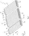
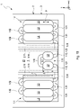
- the storage arrangement 1 shown for a vehicle for storing and releasing a compressed gas consists of several storage tubes 1.0, each of which is combined in groups to form a first storage tube section 1.1, a second storage tube section 1.2 and a third storage tube section 1.3, with the first and second storage tube sections 1.1 and 1.2 being connected via a fluid connection means 1.12 designed as a connecting tube 1.120, forming an intermediate space Z1, and the second and third tubular storage sections 1.2 and 1.3 are fluidly connected via a connecting tube 1.130 as a further fluid connecting means 1.13, forming an intermediate space Z2.
- Each of the three pipe storage sections 1.1, 1.2 and 1.3 consists of two layers L1 and L2 of pipe storage 1.0 and lie parallel to one another with respect to their longitudinal direction S in such a way as to save space so that adjacent pipe storage units from the lower layer L1 and the upper layer L2 are offset by 60° with respect to their longitudinal axis are, d. H. the circular circumference of a pipe store 1.0 lies tangentially to the circular circumferences of the pipe store 1.0 lying in the adjacent layer L1 or L2.
- the tube storage 1.0 of the tube storage sections 1.1, 1.2 and 1.3 are each fluidly connected at the same axial ends by means of tube storage loops 1.01 and 1.02, so that a meandering fluid path is created.
- the compressed gas is routed upwards, for example, from an input E of a tube store 1.0 in the lower layer L1 into a directly adjacent tube store 1.0 in the second layer L2 and then back down into a directly adjacent tube store 1.0 in the first layer, etc.
- the connecting pipe 1.12 connecting the two pipe storage sections 1.1 and 1.2 connects the same axial ends of the adjacent pipe storage 1.0 of the first and second pipe storage sections 1.1 and 1.2 in the first layer L1 and therefore runs horizontally in the plane formed by the first layer L1.
- the two pipe storage sections 1.2 and 1.3 are fluidly connected on the opposite side via the same axial ends of the adjacent pipe storage 1.0 of the second and third pipe storage sections 1.2 and 1.3 in the first layer L1 by means of the connecting pipe 1.13, which is also horizontal in the first layer L1 formed level runs.
- the spaces Z1 and Z2 created by the spaced tubular storage sections 1.1, 1.2 and 1.3 are used for the installation of cross members 2.1 and 2.2 to be connected to the structure of a vehicle body (cf. figure 2 ) used.
- the two crossbeams 2.1 and 2.2 are arranged in the spaces Z1 and Z2 in the plane formed by the second layer L2, i.e. they are aligned with the pipe stores 1.0 of the second plane L2, without crossing the area of the connecting pipes 1.12 and 1.13.
- the cross section of these crossbeams 2.1 and 2.2 is due to the distance b1 (cf.
- FIG 3 of the two pipe storage tanks 1.0 adjoining the intermediate space Z1 or Z2 in the second layer L2 and on the other hand to the diameter D (cf. figure 3 ) the pipe storage 1.0 adjusted so that the height of the crossbeams 2.1 and 2.2 does not exceed the pipe storage 1.0 of the second layer L2.
- the two crossbeams 2.1 and 2.2 in the storage arrangement 1 are shown figure 1 not shown.
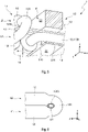
- FIG. 2.1 An alternative embodiment with regard to the cross-sectional shape of the cross members 2.1 and 2.2 shows figure 3 using the cross member 2.1.
- This crossbeam 2.1 also partially utilizes the space between the storage tube 1.0 connected to the connecting tube 1.12, since the diameter d1 of the connecting tube 1.12 is smaller than the diameter D of a storage tube 1.0.
- the cross member 2.1 to be adapted to this intermediate space Z1 with a T-shaped cross section, with the transverse section of the T shape being adapted to the distance b1 of the pipe store 1.0 of the second layer L2 adjoining the intermediate space Z1 and thus to the cross section of the cross member 2.1 after figure 2 corresponds, while the longitudinal section of the T-shape along the distance b2 between the tube store 1.0 of the first layer L1 adjoining the intermediate space Z1 is adapted to the edge of the connecting pipe 1.12 running in the direction of the pipe store 1.0 of the second layer L2.
- the distance between the pipe stores 1.0 between the pipe stores 1.0 of the first layer L1 is denoted by the reference symbol b3, where b3 ⁇ b2 applies.
- the figure 4 shows a memory arrangement 1 designed as an assembly with the figure 1 illustrated pipe storage 1.0.
- the tube accumulator 1.0 corresponding to those according to figure 1 also grouped at a distance into three tube storage sections 1.1, 1.2 and 1.3 to form the intermediate spaces Z1 and Z2.
- These intermediate spaces Z1 and Z2 are also bridged at the edge by a connecting pipe 1.12 and 1.13 aligned with the first layer for the fluid connection of the individual pipe storage sections 1.1, 1.2 and 1.3.
- This arrangement of the three spaced-apart pipe storage sections 1.1, 1.2 and 1.3 is framed by a frame support 3, which is essentially rectangular in shape with four frame elements 3.3, 3.4, 3.5 and 3.6.
- the frame support 3.3 is arranged on one side of the axial ends of the tube store 1.0 and the frame support 3.4 on the opposite side, while the frame supports 3.5 and 3.6 connecting the two frame elements 3.3 and 3.4 run in the longitudinal direction S of the tube store 1.0.
- This frame support 3 also includes a crossbar 3.1 and a crossbar 3.2, which are arranged in the space Z1 between the first and second tube storage section 1.1 and 1.2 or in the space Z2 between the second and third tube storage section 1.2 and 1.3 and the two frame elements 3.3 and 3.4 of the frame support 3 connect non-positively.
- the two transverse webs 3.1 and 3.2 run in the plane formed by the first layer L1 of the pipe storage 1.0, i.e. they are aligned with the pipe storage 1.0 of the first level L1 and therefore cross the connecting pipes 1.12 and 1.12 fluidly connecting the pipe storage sections 1.1, 1.2 and 1.3 1.13. Therefore, the area of the crossbar 3.1, where the connecting tube 1.12 is passed through, is provided with a cutout 3.10, as shown in FIG figure 5 is evident. As a result, the cross section of the transverse web 3.1 is reduced to a narrow web 3.11, which is non-positively connected to the frame element 3.4.
- the transverse web 3.1 is adapted in its cross section to the intermediate space Z1 between the adjacent pipe stores 1.0 of the first layer L1 in the first layer L1 such that their width is the distance b3 between these two pipe stores 1.0 and the height is slightly greater than the diameter D of the pipe stores 1.0 (cf. figure 3 ).
- the transverse web 3.1 thus protrudes only downwards by a projection a beyond the first layer L1, but does not protrude upwards in the direction of the tube storage 1.0 of the second layer L2 beyond the tube storage 1.0 of the first layer. In this direction upwards, the cross member 2.1 closes with a corresponding of figure 2 executed cross section. In this way, the cross bar 3.1 can be produced in one piece together with the cross member 2.1.
- the transverse web 3.2 arranged between the second tubular storage section 1.2 and the third raw storage section 1.3 is designed in a corresponding manner and has a cutout 3.20 for the passage of the connecting pipe 1.13.
- the cross section of this transverse web 3.2 is also adapted to the width b3 of the intermediate space Z2 transversely to the longitudinal direction S of the pipe storage 1.0 and is slightly larger than the diameter D of the pipe storage 1.0, so that the transverse web 3.2 does not go above the pipe storage in the direction of the second layer L2 1.0 of the first layer protrudes, but towers over the tube storage 1.0 of the first layer L1 downwards with a supernatant a.
- the frame support 3 is also designed relative to the three pipe storage sections 1.1, 1.2 and 1.3 in such a way that the frame elements 3.3 to 3.6, in adaptation to the two transverse webs 3.1 and 3.2, run in the plane of the first layer L1 of the pipe storage 1.0, i.e. not upwards the storage tubes 1.0 of the first layer L1 protrude, but project beyond the storage tubes 1.0 of the first layer L1 with the overhang a at the same height corresponding to the transverse webs 3.1 and 3.2.
- figure 5 is the in the figures 1 and 2 described crossbeam 2.1, which is aligned with the crossbar 3.1 in the intermediate space Z1 and at the height of the pipe storage 1.0 of the second layer L2, so that the crossbeam 2.1 is the pipe storage 1.0 of the second layer L2 upwards, i.e. in the opposite direction to the first layer L1 not towered over.
- this cross member is 2.1 and the cross member 2.2 according to figure 2 in the representation of the memory arrangement 1 after figure 4 not marked.
- the frame support 3 is non-positively connected to the cross members 2.1 and 2.2 via attachment points 3.0 of the two crosspieces 3.1 and 3.2.
- the storage arrangement 1 consisting of three tube storage sections 1.1, 1.2 and 1.3 together with the frame support 3, can be non-positively connected to the structure of the vehicle body not only via the cross members 2.1 and 2.2, but also the frame support 3 by means of on the frame elements 3.3, 3.4, 3.5 and 3.6 provided attachment points 3.0.
- the frame element 3.6 of the frame support 3 is after figure 4 not in a straight line, but with a slight bulge pointing outwards, so that an installation space Z3 for valves and a pressure control unit is created between the third tubular storage section 1.3 and the frame element 3.6.
- the frame support 3 after figure 4 has, in addition to the frame elements 3.1 to 3.6, a rod-shaped fastening carrier 4.1 running parallel to the frame element 3.4 and another rod-shaped fastening carrier 4.2 running parallel to the frame element 3.3, which are each connected at the ends with the frame elements 3.5 and 3.6 in a non-positive manner.
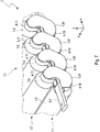
- the fastening support 4.1 is guided perpendicularly to the longitudinal direction S of the pipe storage 1.0 through the openings 1.010 of the pipe storage loops 1.01 located at the same axial end of the pipe storage 1.0, as is detailed in figure 6 is shown.
- the other fastening support 4.2 is passed through the openings 1.020 of the tube storage loops 1.02 on the opposite side.
- the cross section of these fastening supports 4.1 and 4.2 is in line with the contour of the openings 1.010 and 1.020 of the tube storage loops 1.01 and 1.02 as shown in the illustration figure 5 customized.
- these mounting brackets 4.1 and 4.2 run in the plane formed by the pipe stores 1.0 of the first layer L1, they must be guided through the transverse webs 3.1 and 3.2 and have corresponding cutouts for this purpose.
- the already existing cutouts 3.10 and 3.20 of the transverse webs 3.1 and 3.2 serve this purpose.
- Further cutouts 3.12 and 3.21 are provided at the opposite ends of the transverse webs for the passage of the fastening supports 4.1 and 4.2.
- the cutouts 3.10 and 3.12 in the crossbar 3.1 or the cutouts 3.20 and 3.21 in the crossbar 3.2 can each have the same end configuration.
- the pipe storage loops 1.01 and 1.02 are non-positively connected to the mounting brackets 4.1 and 4.2 by means of mounting brackets 4.10 and 4.11 designed as pipe clamps, as is the case for the mounting bracket 4.1 in figure 7 is shown.
- the pipe storage loops 1.01 are each positively connected to the fastening support 4.1 with fastening straps 4.10 at their lower end connected to pipe storage 1.0 of the first layer L1 and on the other hand with fastening straps 4.11 to the fastening support 4.1 at their upper end connected to pipe storage 1.0 of the second layer L2 .
- the memory arrangement designed as an assembly figure 4 is connected to the structure of the body of the vehicle via the cross members 2.1 and 2.2 and thereby integrated into it, for example by the frame support 3 being non-positively connected to the underbody of the vehicle body via attachment points 3.0.
- a seal 3.7 for soundproofing can be provided on the frame elements 3.3 to 3.6 of the frame girder.
- the figure 8 shows a further embodiment of the storage arrangement 1 as an assembly for assembly and integration into a vehicle body.
- a mounting frame 2 with a structure congruent to the frame beam 3 is connected to this frame beam 3 .
- This mounting frame 2 includes in addition to the two cross members 2.1 and 2.2 according to the representations of Figures 2, 3 and 4 Support elements 2.3, 2.4, 2.5 and 2.6.
- This fastening frame 2 is placed with its support elements 2.3 to 2.6 on the frame support 3 in such a way that the individual support elements 2.3 to 2.6 lie congruently on the corresponding frame elements 3.3 to 3.6 of the frame support 3; this of course also applies to the two cross members 2.1 and 2.2 and the two crossbars 3.1 and 3.2.
- the mounting frame 2 is in the plane of the second layer L2 formed by the tube stores 1.0.
- the intermediate spaces formed by the carrier elements 2.3 to 2.6 and the crossbeams 2.1 and 2.2 are closed by means of cover elements 2.7, 2.8 and 2.9.
- the cover element 2.7 closes the area between the cross member 2.1 and the support element 2.5, the cover element 2.8 the area between the two cross members 2.1 and 2.2 and finally the cover element 2.9 the area between the cross member 2.2 and the support
- cover elements 2.70, 2.80 and 2.90 form a base plate with a sufficient distance to the storage tubes 1.0 of the first layer L1, since the frame support 3 together with the transverse webs 3.1 and 3.2 lower the storage tubes 1.0 of the first layer L1 downwards in the vertical direction of the vehicle (z-direction). the supernatant a (cf. figure 5 ) surmounted. This is the case when a force acts on the vehicle from below, ie on the storage arrangement 1 figure 8 there is sufficient deformation path to avoid damage to the storage tubes 1.0.
- the mounting frame 2 has mounting points 2.0, via which the storage arrangement 1 figure 7 are non-positively connected to carriers of the vehicle body.
- fastening frame 2 together with the frame support 3 in one piece.
- the memory arrangement 1 can figure 4 and so after figure 8 can also only be designed with two tubular storage sections 1.1 and 1.2, so that only one crossbeam 2.1 or only one crossbar 3.1 is required for the frame beam 3 or the mounting frame 2.
- This memory arrangement designed as an assembly 1 after figure 8 assumes a structural function in the vehicle in that this assembly can absorb high forces via the components 2.1 to 2.6 of the mounting frame 2, also via the transverse webs 3.1 and 3.2, both in the longitudinal direction of the vehicle (x-direction) and in the transverse direction of the vehicle (y-direction).
- FIG. 9 An alternative embodiment of the memory arrangement 1 after figure 8 is in the figures 9 and 10 shown, this storage arrangement 1 having only two storage tube sections, namely a first storage tube section 1.1 and a second storage tube section 1.2.
- this memory arrangement 1 consists of the two pipe storage sections 1.1 and 1.2 separating cross member 2.1 of the storage arrangement 1 after figure 8 from two partial cross members 2.10 and 2.11, which are arranged at a distance A from one another to form the intermediate space Z1 in the longitudinal direction of the vehicle (x-direction).
- the two partial crossbeams 2.10 and 2.11 also run in the plane of the second layer L2 of the tube storage 1.0 of the two tube storage sections 1.1 and 1.2 corresponding to the crossbeam 2.1 of the storage arrangement 1 figure 4 or figure 8 .
- the two tube storage sections 1.1 and 1.2 are fluidly connected by means of a fluid connection means 1.12 designed as a connecting tube 1.120, the length of the connecting tube 1.120 being adapted to the distance A so that the intermediate space Z1 is bridged.
- the storage arrangement 1 also has a transverse web 3.1, which consists of two partial transverse webs 3.13 and 3.14 running in the plane of the first layer L1 of the pipe storage 1.0 of the two pipe storage sections 1.1 and 1.2, each of which is connected to a partial cross member 2.10 and 2.11 in the vertical direction of the vehicle ( z-direction) are aligned.
- the connecting tube 1.120 runs in the first layer L1 of the tube store 1.0 of the two tube store sections 1.1 and 1.2 and breaks through the two partial transverse webs 3.13 and 3.14, which have corresponding cutouts 3.10.
- the frame support 3 can also be made in one piece with the mounting frame 2 and form a housing for the tube storage 1.0.
- this memory array 1 In an integration of this memory array 1 according to figures 9 and 10 In a vehicle, the area of the space Z1 between front seats and a rear seat bench of the vehicle is located and forms a foot garage 5 for the rear passengers to put their feet. In figure 9 the course of a passenger cell floor 6 of the vehicle is shown schematically, with the intermediate space Z1 forming the foot garage 5 .
- the pipe storage 1.0 of the two pipe storage sections 1.1 and 1.2 are each connected to pipe storage loops 1.01 and 1.02, with according to the figures 9 and 10 the pipe storage 1.0 of the first layer L1 and the second layer L2 are alternately connected, as indicated by the arrows P1 figure 9 is shown.
- the tube storage 1.0 of the respective tube storage sections 1.1 and 1.2 can also be fluidly connected in layers, as indicated by the arrows P2 (shown in broken lines) according to FIG figure 9 is shown.
- the intermediate space Z1 used as a footwell 5 according to the storage arrangement 1 figure 9 and 10 can also be used for arranging further pipe stores 1.0 in the plane of the first layer L1, resulting in a foot garage 5 with a smaller depth in the vertical direction of the vehicle.
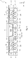
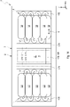
- FIG figures 11 and 12 Such a memory arrangement 1 is shown in FIG figures 11 and 12 , In which in the intermediate space Z1 an intermediate section 1.10 tube store with, for example, three tube stores 1.0 is arranged. These storage tubes 1.0 of the intermediate section 1.10 of the storage tube lie in the plane of the first layer L1 and are fluidly connected in a meandering manner by means of tube storage loops 1.01 and 1.02.
- first and second pipe storage sections 1.1 and 1.2 are each made up of two layers L1 and L2 of pipe storage systems 1.0 creates a foot garage 5 in the intermediate space Z1 due to the pipe storage systems 1.0 of the intermediate pipe storage section 1.10 being reduced by one layer compared to the pipe storage sections 1.1 and 1.2, such as this can be seen from the course of a schematically indicated passenger compartment floor 6 .
- the fluid connection of the intermediate storage tube section 1.10 with the adjacent storage tube sections 1.1 and 1.2 is effected by means of a fluid connection means 1.12 which, as a first connecting pipe section 1.121, fluidly connects the adjacent storage tubes 1.0 of the first storage pipe section 1.1 and of the intermediate storage pipe section 1.10 and which, as a second connecting pipe section 1.122, connects the adjacent storage pipes 1.0 of the second storage pipe section 1.2 and the pipe storage intermediate section 1.10 fluidly connects.
- the two connecting tube sections 1.121 and 1.122 are guided over cutouts 3.10 and 3.12 of the partial transverse webs 3.13 and 3.14.
- the pipe storage 1.0 of the two pipe storage sections 1.1 and 1.2 are each connected to pipe storage loops 1.01 and 1.02, according to the figures 11 and 12 the pipe storage 1.0 of the first layer L1 and the second layer L2 are alternately connected, as indicated by the arrows P1 figure 11 is shown.
- the tube storage 1.0 of the respective tube storage sections 1.1 and 1.2 can also be fluidly connected in layers, as shown by the arrows P2 (dashed line) according to FIG.
- the frame support 3 and the mounting frame 2 of the storage arrangement 1 with the partial transverse webs 3.13 and 3.14 and the partial transverse supports 2.10 and 2.11 are similar to those of the storage arrangement figure 9 and figure 10 constructed and form a housing for the pipe storage 1.0.
- the pipe storage sections 1.1 and 1.2 of the storage arrangement 1 according to figures 11 and 12 can of course also be formed with more than two layers of pipe storage 1.0.
- the pipe store intermediate section 1.10 is designed with a number of layers of pipe stores 1.0 reduced by at least the value 1.
- the memory arrangement 1 according to figures 11 and 12 can also be carried out without the first or second storage tube section 1.1 or 1.2, so that the storage arrangement 1 is produced from the intermediate storage tube section 1.10 as the first storage tube section with the foot garage 5 and another storage tube section as the second storage tube section 1.2.
- the figure 13 shows a memory arrangement 1 according to FIG figures 11 and 12 alternative storage arrangement 1 with an intermediate pipe storage section 1.10 also arranged in the intermediate space Z1 with, for example, two pipe storages 1.0.
- the difference to the memory arrangement 1 according to the figures 11 and 12 is that the two pipe storage 1.0 of the pipe storage intermediate section 1.10 in the longitudinal direction S, ie in the vehicle transverse direction (y-direction) with a length B shorter compared to the length b of the pipe storage 1.0 of the two pipe storage sections 1.1 and 1.2 are executed, so B ⁇ b applies.
- the foot garage 5.1 has a greater depth in the vertical direction of the vehicle than the foot garage 5.
- the pipe storage sections 1.1 and 1.2 can be formed with more than two layers of pipe storage 1.0.
- the pipe store intermediate section 1.10 then has at least a number of layers of pipe stores 1.0 reduced by the value 1.
- the memory arrangement 1 can figure 13 corresponding to the memory arrangement 1 according to the figures 11 and 12 also without the first and second tube storage section 1.1 or 1.2, so that the storage arrangement 1 is produced from the intermediate tube storage section 1.10 as the first pipe storage section with the foot garage 5 and 5.1 and another pipe storage section as the second pipe storage section 1.2.
- the figure 14 shows a memory arrangement 1 according to FIG figures 9 and 10 alternative memory arrangement 1, in which, in contrast to that according to figure 10 the pipe storage 1.0 of the first and second pipe storage sections 1.1 and 1.2 are aligned with their longitudinal direction S perpendicular to the partial cross members 2.10 and 2.11 and thus also perpendicular to the partial transverse webs 3.13 and 3.14, i.e. in the longitudinal direction of the vehicle (x-direction).
- the intermediate space Z1 remains free of pipe storage and forms a foot garage 5.
- the pipe storage 1.0 of the pipe storage sections 1.1 and 1.2 are connected in a meandering manner by means of pipe storage loops 1.01 and 1.02.
- the tube storage loops 1.01 and 1.02 connect respectively adjacent tube storage 1.0 of the first and second layer L1 and L2. It is of course also possible to connect the pipe storage 1.0 in layers in each case.
Landscapes
- Engineering & Computer Science (AREA)
- Mechanical Engineering (AREA)
- General Engineering & Computer Science (AREA)
- Body Structure For Vehicles (AREA)
- Cooling, Air Intake And Gas Exhaust, And Fuel Tank Arrangements In Propulsion Units (AREA)
- Filling Or Discharging Of Gas Storage Vessels (AREA)
Claims (9)
- Système de stockage (1) pour un véhicule destiné à stocker et à fournir un gaz sous pression comprenant :- une première section d'accumulateurs tubulaires (1.1) avec plusieurs accumulateurs tubulaires (1.0) agencés longitudinalement parallèlement les uns aux autres en une première couche (L1) et au moins en une seconde couche (L2), qui sont en communication fluidique en forme de méandres au niveau de leurs extrémités axiales au moyen de boucles d'accumulateurs tubulaires (1.01, 1.02),- au moins une seconde section d'accumulateurs tubulaires (1.2) avec plusieurs accumulateurs tubulaires (1.0) agencés longitudinalement parallèlement les uns aux autres en une première couche (L1) et au moins en une seconde couche (L2), qui sont en communication fluidique en forme de méandres au niveau de leurs extrémités axiales au moyen de boucles d'accumulateurs tubulaires (1.01, 1.02), et- un moyen de connexion fluidique (1.12, 1.13) pour connecter fluidiquement les première et seconde sections d'accumulateurs tubulaires (1.1, 1.2),
caractérisé en ce que- les moyens de connexion fluidique (1.12, 1.13) connectent fluidiquement chacune des mêmes extrémités axiales de soit deux accumulateurs tubulaires (1.0) adjacents sur un plan dans la première couche (L1) ou de deux accumulateurs tubulaires (1.0) adjacents sur un plan dans la seconde couche (L2), et- un espace intermédiaire (Z1) est prévu entre les première et seconde sections d'accumulateurs tubulaires (1.1, 1.2) pour recevoir une poutre transversale (2.1) de la carrosserie du véhicule, qui est aligné avec la seconde couche (L2) d'accumulateurs tubulaires (1.0) lorsque le moyen de connexion fluidique (1.12, 1.13) est aligné avec la première couche (L1) des accumulateurs tubulaires (1.0), ou aligné avec la première couche (L1) des accumulateurs tubulaires (1.0) lorsque le moyen de connexion fluidique (1.12) est aligné avec la seconde couche (L2) des accumulateurs tubulaires (1.0). - Système de stockage (1) selon la revendication 1,
caractérisé en ce que le système de stockage (1) présente un support de cadre (3) encadrant la première section d'accumulateurs tubulaires (1.1) et la seconde section d'accumulateurs tubulaires (1.2). - Système de stockage (1) selon la revendication 2,
caractérisé en ce que le système de stockage (1) comprend une traverse (3.1) agencée entre les première et seconde sections d'accumulateurs tubulaires (1.1, 1.2), qui est alignée avec la première ou la seconde couche (L1, L2) avec laquelle le moyen de connexion fluidique (1.12) est également aligné, dans lequel le moyen de connexion fluidique (1.12) est guidé à travers la traverse (3.1) et la traverse (3.1) est connectée à force côté extrémité au support de cadre (3). - Système de stockage (1) selon l'une quelconque des revendications précédentes,
caractérisé en ce que le système de stockage (1) présente au moins un support de fixation en forme de tige (4.1) qui est guidé à travers les ouvertures (1.010) des boucles d'accumulateurs tubulaires (1.01) situées au niveau de la même extrémité axiale des accumulateurs tubulaires (1.0) et est connecté à force au support de cadre (3). - Système de stockage (1) selon l'une quelconque des revendications précédentes,
caractérisé en ce que le moyen de connexion fluidique (1.12, 1.13) est réalisé sous la forme d'un tuyau de raccordement (1.120, 1.130). - Système de stockage (1) selon l'une quelconque des revendications précédentes,
caractérisé en ce que le système de stockage (1) est réalisé avec une section intermédiaire d'accumulateurs tubulaires (1.10) agencée dans l'espace intermédiaire (Z1) avec plusieurs accumulateurs tubulaires (1.0) agencés longitudinalement parallèlement en au moins la première couche (L1), qui sont en communication fluidique en forme de méandres au niveau de leurs extrémités axiales au moyen de boucles d'accumulateurs tubulaires (1.01, 1.02), dans lequel- le nombre de couches des accumulateurs tubulaires (1.0) de la section intermédiaire d'accumulateurs tubulaires (1.10) est inférieur d'au moins une couche par rapport au nombre de couches des accumulateurs tubulaires de la première et/ou de la seconde section d'accumulateurs tubulaires (1.1, 1.2), et- le moyen de connexion fluidique (1.12) s'étendant dans la première couche (L1) des accumulateurs tubulaires (1.0) consiste en une première section de tuyau de raccordement (1.121) reliant fluidiquement les accumulateurs tubulaires (1.0) adjacents de la première section d'accumulateurs tubulaires (1.1) et de la section intermédiaire d'accumulateurs tubulaires (1.10) et en une seconde section de tuyau de raccordement (1.122) reliant fluidiquement les accumulateurs tubulaires (1.0) adjacents de la seconde section d'accumulateurs tubulaires (1.2) et de la section intermédiaire d'accumulateurs tubulaires (1.10). - Système de stockage selon la revendication 6,
caractérisé en ce qu'au moins une couche (L1) des accumulateurs tubulaires (1.0) de la section intermédiaire d'accumulateurs tubulaires (1.10) est réduite dans la direction longitudinale des accumulateurs tubulaires (1.0) par rapport aux accumulateurs tubulaires (1.0) de la première et/ou la seconde section d'accumulateurs tubulaires (1.1, 1.2). - Véhicule comprenant- un système de stockage (1) selon l'une quelconque des revendications précédentes destiné à stocker et à fournir un gaz sous pression, comprenant une poutre transversale (2.1) qui est reliée à force à la carrosserie du véhicule,dans lequel la poutre transversale (2.1) dans l'espace intermédiaire (Z1) entre les première et seconde sections d'accumulateurs tubulaires (1.1, 1.2) est soit alignée avec la seconde couche (L2) des accumulateurs tubulaires (1.0) lorsque le moyen de connexion fluidique (1.12) est aligné avec la première couche (L1) des accumulateurs tubulaires (1.0), ou alignée avec la première couche (L1) des accumulateurs tubulaires (1.0) lorsque le moyen de connexion fluidique (1.12) est aligné avec la seconde couche (L2) des accumulateurs tubulaires (1.0).
- Véhicule selon la revendication 8,
caractérisé en ce que la poutre transversale (2.1) forme conjointement avec des éléments de support (2.3, 2.4, 2.5, 2.6) un cadre de fixation (2) congruent au support de cadre (3), dans lequel les espaces intermédiaires formés par la poutre transversale (2.1) et les éléments de support (2.3, 2.4, 2.5, 2.6) sont fermés au moyen d'éléments de couvercle (2.7, 2.8) et/ou les espaces intermédiaires formés par les éléments de cadre (3.3, 3.4, 3.5, 3.6) et la traverse (3.1) du support de cadre (3) sont fermés au moyen d'éléments de couvercle (2.70, 2.80) et le cadre de fixation (2) est relié à force au support de cadre (3) ou est fabriqué d'un seul tenant.
Applications Claiming Priority (2)
| Application Number | Priority Date | Filing Date | Title |
|---|---|---|---|
| DE102018205967.5A DE102018205967A1 (de) | 2018-04-19 | 2018-04-19 | Fahrzeug mit einer Speicheranordnung zum Speichern und Abgeben eines Druckgases und Speicheranordnung für ein Fahrzeug |
| PCT/EP2019/060038 WO2019202058A1 (fr) | 2018-04-19 | 2019-04-18 | Véhicule muni d'un système de stockage servant à stocker et fournir un gaz sous pression et système de stockage pour véhicule |
Publications (2)
| Publication Number | Publication Date |
|---|---|
| EP3625496A1 EP3625496A1 (fr) | 2020-03-25 |
| EP3625496B1 true EP3625496B1 (fr) | 2022-12-14 |
Family
ID=66334427
Family Applications (1)
| Application Number | Title | Priority Date | Filing Date |
|---|---|---|---|
| EP19720501.6A Active EP3625496B1 (fr) | 2018-04-19 | 2019-04-18 | Véhicule muni d'un système de stockage servant à stocker et fournir un gaz sous pression et système de stockage pour véhicule |
Country Status (6)
| Country | Link |
|---|---|
| US (1) | US11549642B2 (fr) |
| EP (1) | EP3625496B1 (fr) |
| CN (1) | CN111989518B (fr) |
| DE (1) | DE102018205967A1 (fr) |
| ES (1) | ES2935772T3 (fr) |
| WO (1) | WO2019202058A1 (fr) |
Families Citing this family (11)
| Publication number | Priority date | Publication date | Assignee | Title |
|---|---|---|---|---|
| DE102019130030A1 (de) * | 2019-11-07 | 2021-05-12 | Bayerische Motoren Werke Aktiengesellschaft | Kraftfahrzeug |
| DE102019132060A1 (de) * | 2019-11-27 | 2021-05-27 | Bayerische Motoren Werke Aktiengesellschaft | Verfahren zum Herstellen eines Kraftfahrzeugs und Verfahren zum Herstellen einer Mehrzahl von Kraftfahrzeugen |
| DE102020101169A1 (de) * | 2020-01-20 | 2021-06-02 | Audi Aktiengesellschaft | Fahrzeug mit einer Speicheranordnung zum Speichern und Abgeben eines Druckgases |
| DE102020101170A1 (de) | 2020-01-20 | 2021-07-22 | Audi Aktiengesellschaft | Fahrzeug mit einer Speicheranordnung zum Speichern und Abgeben eines Druckgases |
| DE102020101165B4 (de) | 2020-01-20 | 2023-06-01 | Audi Aktiengesellschaft | Fahrzeug mit einem Druckgasspeicher |
| DE102020101168A1 (de) * | 2020-01-20 | 2021-06-02 | Audi Aktiengesellschaft | Fahrzeug mit einer Speicheranordnung zum Speichern und Abgeben eines Druckgases |
| DE102020101167A1 (de) | 2020-01-20 | 2021-07-22 | Audi Aktiengesellschaft | Speicheranordnung für ein Fahrzeug zum Speichern und Abgeben eines Druckgases sowie Fahrzeug mit einer solchen Speicheranordnung |
| DE102020103077A1 (de) | 2020-02-06 | 2021-08-12 | Audi Aktiengesellschaft | Fahrzeug mit einer Speicheranordnung zum Speichern und Abgeben eines Druckgases |
| DE102020106083A1 (de) | 2020-03-06 | 2021-09-09 | Audi Aktiengesellschaft | Lastzug, Zugmaschine, Anhänger sowie Be- und Entladeterminal |
| DE102020113473B4 (de) | 2020-05-19 | 2023-10-12 | Audi Aktiengesellschaft | Drucktankanordnung mit verbesserten Crasheigenschaften und Kraftfahrzeug mit einer solchen Drucktankanordnung |
| CN113022706A (zh) * | 2021-04-15 | 2021-06-25 | 武汉雄韬氢雄燃料电池科技有限公司 | 一种用于氢能源汽车的新型氢气储存装置 |
Family Cites Families (20)
| Publication number | Priority date | Publication date | Assignee | Title |
|---|---|---|---|---|
| US4932403A (en) | 1989-04-14 | 1990-06-12 | Scholley Frank G | Flexible container for compressed gases |
| JP2001317689A (ja) * | 2000-05-01 | 2001-11-16 | Mitsubishi Rayon Co Ltd | 圧力タンク |
| ITMC20010086A1 (it) | 2001-08-20 | 2003-02-20 | Sida Engineering Srl | Serbatoio multicelle per gas in pressione |
| AU2003270699B2 (en) | 2002-09-17 | 2010-08-19 | Alexander S. Pouchkarev | Multilayered pressure vessel and method of manufacturing the same |
| DE202006004434U1 (de) | 2006-03-21 | 2006-06-08 | Otto Fuchs Kg | Kraftstoffbehälteranordnung zum Speichern druckbeaufschlagter Gase für ein Kraftfahrzeug |
| MY173481A (en) | 2009-02-24 | 2020-01-28 | Nissan Motor | Vehicle battery mounting structure |
| DE102011012496B4 (de) | 2011-02-25 | 2023-09-14 | Volkswagen Ag | Fahrzeug |
| US9217538B2 (en) | 2012-05-03 | 2015-12-22 | Other Lab, Llc | Conformable natural gas storage |
| CN104968987B (zh) * | 2013-02-05 | 2018-07-13 | 奥特尔实验室有限责任公司 | 肠状堆积的天然气储罐 |
| US9174531B2 (en) * | 2013-06-19 | 2015-11-03 | Fca Us Llc | Modular fuel storage system |
| US10222001B2 (en) | 2013-11-08 | 2019-03-05 | United Technologies Corporation | High conformal pressure vessel |
| CN203666380U (zh) * | 2013-12-19 | 2014-06-25 | 北京汽车股份有限公司 | 车辆及其天然气储气装置 |
| US9033085B1 (en) | 2014-02-20 | 2015-05-19 | Atieva, Inc. | Segmented, undercarriage mounted EV battery pack |
| WO2016205372A2 (fr) | 2015-06-15 | 2016-12-22 | Other Lab Llc | Système et procédé pour récipient de pression adaptable |
| US9850852B2 (en) * | 2015-07-30 | 2017-12-26 | Third Shore Group, LLC | Compressed gas capture and recovery system |
| US11000988B2 (en) * | 2015-12-02 | 2021-05-11 | Other Lab, Llc | Systems and methods for liner braiding and resin application |
| BR102017010041A2 (pt) | 2016-05-16 | 2017-11-28 | Goodrich Corporation | Adaptable pressure container, and, aircraft emergency evacuation system |
| US9878611B1 (en) | 2016-07-29 | 2018-01-30 | GM Global Technology Operations LLC | Vehicle with natural gas storage array |
| US10717356B2 (en) | 2017-08-09 | 2020-07-21 | Toyota Jidosha Kabushiki Kaisha | High pressure canister unit and fuel cell vehicle |
| JP7067241B2 (ja) | 2017-08-09 | 2022-05-16 | トヨタ自動車株式会社 | 高圧容器ユニット及び燃料電池車両 |
-
2018
- 2018-04-19 DE DE102018205967.5A patent/DE102018205967A1/de not_active Ceased
-
2019
- 2019-04-18 EP EP19720501.6A patent/EP3625496B1/fr active Active
- 2019-04-18 WO PCT/EP2019/060038 patent/WO2019202058A1/fr unknown
- 2019-04-18 ES ES19720501T patent/ES2935772T3/es active Active
- 2019-04-18 US US17/047,903 patent/US11549642B2/en active Active
- 2019-04-18 CN CN201980026263.0A patent/CN111989518B/zh active Active
Also Published As
| Publication number | Publication date |
|---|---|
| CN111989518B (zh) | 2022-03-01 |
| WO2019202058A1 (fr) | 2019-10-24 |
| US20210164615A1 (en) | 2021-06-03 |
| US11549642B2 (en) | 2023-01-10 |
| CN111989518A (zh) | 2020-11-24 |
| EP3625496A1 (fr) | 2020-03-25 |
| DE102018205967A1 (de) | 2019-10-24 |
| ES2935772T3 (es) | 2023-03-09 |
Similar Documents
| Publication | Publication Date | Title |
|---|---|---|
| EP3625496B1 (fr) | Véhicule muni d'un système de stockage servant à stocker et fournir un gaz sous pression et système de stockage pour véhicule | |
| EP1934120B1 (fr) | Rayonnage dote d'une pluralite d'unites de rayonnage | |
| DE4009401C2 (fr) | ||
| WO2020120068A1 (fr) | Bloc plancher à accumulateur d'énergie pour une coque de véhicule à moteur | |
| EP1717107B1 (fr) | Pare-chocs pourvu de supports de fixation | |
| EP1654150B1 (fr) | Structure de noeud pour relier deux profiles dans un cadre porteur de vehicule | |
| DE3343682A1 (de) | Tragender aufbau fuer ein kraftfahrzeug | |
| DE102018132255A1 (de) | Energiespeicher-Bodengruppe für einen Kraftwagenrohbau | |
| DE102006058993A1 (de) | Hilfsrahmen für ein Kraftfahrzeug | |
| DE102018210699B4 (de) | Fahrzeug mit einem Elektroantrieb und einem Hybrid-Energiespeicher | |
| EP1819576A1 (fr) | Faux chassis pour cadre de chassis de vehicule utilitaire | |
| EP1985508A2 (fr) | Elément de déformation absorbant l'énergie pour un véhicule | |
| WO2018166895A1 (fr) | Logement de batterie comprenant une structure de renforcement et utilisation | |
| DE202005017269U1 (de) | Lagerregal mit einer Vielzahl von Regaleinheiten | |
| EP3016843B1 (fr) | Convoyeur aérien équipé de modules de châssis porteur | |
| WO2014023273A1 (fr) | Dispositif de transport surélevé doté de portiques à colonnes | |
| DE102012014775A1 (de) | Vorrichtung zur Anordnung von Batteriemodulen in einer Fahrzeugbatterie | |
| DE102017127064A1 (de) | Batterierahmen | |
| DE102010048350A1 (de) | Bodengruppe für eine Mehrzahl von Bauvarianten einer Karosserie eines Personenkraftwagens | |
| DE102018132257A1 (de) | Vorderachsträger-Anordnung an einem elektrisch betreibbaren Kraftwagen | |
| DE102013016456A1 (de) | Unterbau für ein Kraftfahrzeug | |
| EP1331159B1 (fr) | Structure de châssis pour véhicule automobile | |
| DE19517918A1 (de) | Fahrzeugrahmen | |
| DE102020202883A1 (de) | Unterbaustruktur für ein Fahrzeug | |
| DE102018120774B4 (de) | Wabenregal zur Lagerung von Lagergut sowie Wabenregalgestell |
Legal Events
| Date | Code | Title | Description |
|---|---|---|---|
| STAA | Information on the status of an ep patent application or granted ep patent |
Free format text: STATUS: UNKNOWN |
|
| STAA | Information on the status of an ep patent application or granted ep patent |
Free format text: STATUS: THE INTERNATIONAL PUBLICATION HAS BEEN MADE |
|
| PUAI | Public reference made under article 153(3) epc to a published international application that has entered the european phase |
Free format text: ORIGINAL CODE: 0009012 |
|
| STAA | Information on the status of an ep patent application or granted ep patent |
Free format text: STATUS: REQUEST FOR EXAMINATION WAS MADE |
|
| 17P | Request for examination filed |
Effective date: 20191217 |
|
| AK | Designated contracting states |
Kind code of ref document: A1 Designated state(s): AL AT BE BG CH CY CZ DE DK EE ES FI FR GB GR HR HU IE IS IT LI LT LU LV MC MK MT NL NO PL PT RO RS SE SI SK SM TR |
|
| AX | Request for extension of the european patent |
Extension state: BA ME |
|
| RIN1 | Information on inventor provided before grant (corrected) |
Inventor name: SCHUETZ, THORSTEN Inventor name: ALBL, SEBASTIAN Inventor name: HOCHGRAEBER, FELIX Inventor name: HOFMANN, FRANZ |
|
| DAV | Request for validation of the european patent (deleted) | ||
| DAX | Request for extension of the european patent (deleted) | ||
| GRAP | Despatch of communication of intention to grant a patent |
Free format text: ORIGINAL CODE: EPIDOSNIGR1 |
|
| STAA | Information on the status of an ep patent application or granted ep patent |
Free format text: STATUS: GRANT OF PATENT IS INTENDED |
|
| INTG | Intention to grant announced |
Effective date: 20220929 |
|
| GRAS | Grant fee paid |
Free format text: ORIGINAL CODE: EPIDOSNIGR3 |
|
| GRAA | (expected) grant |
Free format text: ORIGINAL CODE: 0009210 |
|
| STAA | Information on the status of an ep patent application or granted ep patent |
Free format text: STATUS: THE PATENT HAS BEEN GRANTED |
|
| AK | Designated contracting states |
Kind code of ref document: B1 Designated state(s): AL AT BE BG CH CY CZ DE DK EE ES FI FR GB GR HR HU IE IS IT LI LT LU LV MC MK MT NL NO PL PT RO RS SE SI SK SM TR |
|
| REG | Reference to a national code |
Ref country code: GB Ref legal event code: FG4D Free format text: NOT ENGLISH |
|
| REG | Reference to a national code |
Ref country code: CH Ref legal event code: EP |
|
| REG | Reference to a national code |
Ref country code: DE Ref legal event code: R096 Ref document number: 502019006528 Country of ref document: DE |
|
| REG | Reference to a national code |
Ref country code: IE Ref legal event code: FG4D Free format text: LANGUAGE OF EP DOCUMENT: GERMAN |
|
| REG | Reference to a national code |
Ref country code: AT Ref legal event code: REF Ref document number: 1537870 Country of ref document: AT Kind code of ref document: T Effective date: 20230115 |
|
| REG | Reference to a national code |
Ref country code: DE Ref legal event code: R084 Ref document number: 502019006528 Country of ref document: DE |
|
| REG | Reference to a national code |
Ref country code: ES Ref legal event code: FG2A Ref document number: 2935772 Country of ref document: ES Kind code of ref document: T3 Effective date: 20230309 |
|
| REG | Reference to a national code |
Ref country code: LT Ref legal event code: MG9D |
|
| REG | Reference to a national code |
Ref country code: NL Ref legal event code: MP Effective date: 20221214 |
|
| PG25 | Lapsed in a contracting state [announced via postgrant information from national office to epo] |
Ref country code: SE Free format text: LAPSE BECAUSE OF FAILURE TO SUBMIT A TRANSLATION OF THE DESCRIPTION OR TO PAY THE FEE WITHIN THE PRESCRIBED TIME-LIMIT Effective date: 20221214 Ref country code: NO Free format text: LAPSE BECAUSE OF FAILURE TO SUBMIT A TRANSLATION OF THE DESCRIPTION OR TO PAY THE FEE WITHIN THE PRESCRIBED TIME-LIMIT Effective date: 20230314 Ref country code: LT Free format text: LAPSE BECAUSE OF FAILURE TO SUBMIT A TRANSLATION OF THE DESCRIPTION OR TO PAY THE FEE WITHIN THE PRESCRIBED TIME-LIMIT Effective date: 20221214 Ref country code: FI Free format text: LAPSE BECAUSE OF FAILURE TO SUBMIT A TRANSLATION OF THE DESCRIPTION OR TO PAY THE FEE WITHIN THE PRESCRIBED TIME-LIMIT Effective date: 20221214 |
|
| PG25 | Lapsed in a contracting state [announced via postgrant information from national office to epo] |
Ref country code: RS Free format text: LAPSE BECAUSE OF FAILURE TO SUBMIT A TRANSLATION OF THE DESCRIPTION OR TO PAY THE FEE WITHIN THE PRESCRIBED TIME-LIMIT Effective date: 20221214 Ref country code: LV Free format text: LAPSE BECAUSE OF FAILURE TO SUBMIT A TRANSLATION OF THE DESCRIPTION OR TO PAY THE FEE WITHIN THE PRESCRIBED TIME-LIMIT Effective date: 20221214 Ref country code: HR Free format text: LAPSE BECAUSE OF FAILURE TO SUBMIT A TRANSLATION OF THE DESCRIPTION OR TO PAY THE FEE WITHIN THE PRESCRIBED TIME-LIMIT Effective date: 20221214 Ref country code: GR Free format text: LAPSE BECAUSE OF FAILURE TO SUBMIT A TRANSLATION OF THE DESCRIPTION OR TO PAY THE FEE WITHIN THE PRESCRIBED TIME-LIMIT Effective date: 20230315 |
|
| PG25 | Lapsed in a contracting state [announced via postgrant information from national office to epo] |
Ref country code: NL Free format text: LAPSE BECAUSE OF FAILURE TO SUBMIT A TRANSLATION OF THE DESCRIPTION OR TO PAY THE FEE WITHIN THE PRESCRIBED TIME-LIMIT Effective date: 20221214 |
|
| P01 | Opt-out of the competence of the unified patent court (upc) registered |
Effective date: 20230530 |
|
| PG25 | Lapsed in a contracting state [announced via postgrant information from national office to epo] |
Ref country code: SM Free format text: LAPSE BECAUSE OF FAILURE TO SUBMIT A TRANSLATION OF THE DESCRIPTION OR TO PAY THE FEE WITHIN THE PRESCRIBED TIME-LIMIT Effective date: 20221214 Ref country code: RO Free format text: LAPSE BECAUSE OF FAILURE TO SUBMIT A TRANSLATION OF THE DESCRIPTION OR TO PAY THE FEE WITHIN THE PRESCRIBED TIME-LIMIT Effective date: 20221214 Ref country code: PT Free format text: LAPSE BECAUSE OF FAILURE TO SUBMIT A TRANSLATION OF THE DESCRIPTION OR TO PAY THE FEE WITHIN THE PRESCRIBED TIME-LIMIT Effective date: 20230414 Ref country code: EE Free format text: LAPSE BECAUSE OF FAILURE TO SUBMIT A TRANSLATION OF THE DESCRIPTION OR TO PAY THE FEE WITHIN THE PRESCRIBED TIME-LIMIT Effective date: 20221214 Ref country code: CZ Free format text: LAPSE BECAUSE OF FAILURE TO SUBMIT A TRANSLATION OF THE DESCRIPTION OR TO PAY THE FEE WITHIN THE PRESCRIBED TIME-LIMIT Effective date: 20221214 |
|
| PGFP | Annual fee paid to national office [announced via postgrant information from national office to epo] |
Ref country code: IT Payment date: 20230428 Year of fee payment: 5 Ref country code: FR Payment date: 20230425 Year of fee payment: 5 Ref country code: ES Payment date: 20230503 Year of fee payment: 5 Ref country code: DE Payment date: 20230430 Year of fee payment: 5 |
|
| PG25 | Lapsed in a contracting state [announced via postgrant information from national office to epo] |
Ref country code: SK Free format text: LAPSE BECAUSE OF FAILURE TO SUBMIT A TRANSLATION OF THE DESCRIPTION OR TO PAY THE FEE WITHIN THE PRESCRIBED TIME-LIMIT Effective date: 20221214 Ref country code: PL Free format text: LAPSE BECAUSE OF FAILURE TO SUBMIT A TRANSLATION OF THE DESCRIPTION OR TO PAY THE FEE WITHIN THE PRESCRIBED TIME-LIMIT Effective date: 20221214 Ref country code: IS Free format text: LAPSE BECAUSE OF FAILURE TO SUBMIT A TRANSLATION OF THE DESCRIPTION OR TO PAY THE FEE WITHIN THE PRESCRIBED TIME-LIMIT Effective date: 20230414 Ref country code: AL Free format text: LAPSE BECAUSE OF FAILURE TO SUBMIT A TRANSLATION OF THE DESCRIPTION OR TO PAY THE FEE WITHIN THE PRESCRIBED TIME-LIMIT Effective date: 20221214 |
|
| REG | Reference to a national code |
Ref country code: DE Ref legal event code: R097 Ref document number: 502019006528 Country of ref document: DE |
|
| PLBE | No opposition filed within time limit |
Free format text: ORIGINAL CODE: 0009261 |
|
| STAA | Information on the status of an ep patent application or granted ep patent |
Free format text: STATUS: NO OPPOSITION FILED WITHIN TIME LIMIT |
|
| PG25 | Lapsed in a contracting state [announced via postgrant information from national office to epo] |
Ref country code: DK Free format text: LAPSE BECAUSE OF FAILURE TO SUBMIT A TRANSLATION OF THE DESCRIPTION OR TO PAY THE FEE WITHIN THE PRESCRIBED TIME-LIMIT Effective date: 20221214 |
|
| PGFP | Annual fee paid to national office [announced via postgrant information from national office to epo] |
Ref country code: GB Payment date: 20230420 Year of fee payment: 5 |
|
| 26N | No opposition filed |
Effective date: 20230915 |
|
| PG25 | Lapsed in a contracting state [announced via postgrant information from national office to epo] |
Ref country code: SI Free format text: LAPSE BECAUSE OF FAILURE TO SUBMIT A TRANSLATION OF THE DESCRIPTION OR TO PAY THE FEE WITHIN THE PRESCRIBED TIME-LIMIT Effective date: 20221214 |
|
| REG | Reference to a national code |
Ref country code: CH Ref legal event code: PL |
|
| PG25 | Lapsed in a contracting state [announced via postgrant information from national office to epo] |
Ref country code: LU Free format text: LAPSE BECAUSE OF NON-PAYMENT OF DUE FEES Effective date: 20230418 |
|
| REG | Reference to a national code |
Ref country code: BE Ref legal event code: MM Effective date: 20230430 |
|
| PG25 | Lapsed in a contracting state [announced via postgrant information from national office to epo] |
Ref country code: MC Free format text: LAPSE BECAUSE OF FAILURE TO SUBMIT A TRANSLATION OF THE DESCRIPTION OR TO PAY THE FEE WITHIN THE PRESCRIBED TIME-LIMIT Effective date: 20221214 |
|
| PG25 | Lapsed in a contracting state [announced via postgrant information from national office to epo] |
Ref country code: MC Free format text: LAPSE BECAUSE OF FAILURE TO SUBMIT A TRANSLATION OF THE DESCRIPTION OR TO PAY THE FEE WITHIN THE PRESCRIBED TIME-LIMIT Effective date: 20221214 Ref country code: LI Free format text: LAPSE BECAUSE OF NON-PAYMENT OF DUE FEES Effective date: 20230430 Ref country code: CH Free format text: LAPSE BECAUSE OF NON-PAYMENT OF DUE FEES Effective date: 20230430 |
|
| REG | Reference to a national code |
Ref country code: IE Ref legal event code: MM4A |
|
| PG25 | Lapsed in a contracting state [announced via postgrant information from national office to epo] |
Ref country code: BE Free format text: LAPSE BECAUSE OF NON-PAYMENT OF DUE FEES Effective date: 20230430 |
|
| PG25 | Lapsed in a contracting state [announced via postgrant information from national office to epo] |
Ref country code: IE Free format text: LAPSE BECAUSE OF NON-PAYMENT OF DUE FEES Effective date: 20230418 |
|
| PG25 | Lapsed in a contracting state [announced via postgrant information from national office to epo] |
Ref country code: IE Free format text: LAPSE BECAUSE OF NON-PAYMENT OF DUE FEES Effective date: 20230418 |