EP3625496B1 - Vehicle having a storage assembly for storing and dispensing a pressurised gas, and storage assembly for a vehicle - Google Patents
Vehicle having a storage assembly for storing and dispensing a pressurised gas, and storage assembly for a vehicle Download PDFInfo
- Publication number
- EP3625496B1 EP3625496B1 EP19720501.6A EP19720501A EP3625496B1 EP 3625496 B1 EP3625496 B1 EP 3625496B1 EP 19720501 A EP19720501 A EP 19720501A EP 3625496 B1 EP3625496 B1 EP 3625496B1
- Authority
- EP
- European Patent Office
- Prior art keywords
- storage
- layer
- tube
- tubes
- pipe
- Prior art date
- Legal status (The legal status is an assumption and is not a legal conclusion. Google has not performed a legal analysis and makes no representation as to the accuracy of the status listed.)
- Active
Links
- 238000003860 storage Methods 0.000 title claims description 346
- 239000012530 fluid Substances 0.000 claims description 37
- 238000012432 intermediate storage Methods 0.000 claims description 8
- 239000007789 gas Substances 0.000 description 10
- 238000009434 installation Methods 0.000 description 4
- 230000014759 maintenance of location Effects 0.000 description 4
- 230000010354 integration Effects 0.000 description 3
- VNWKTOKETHGBQD-UHFFFAOYSA-N methane Chemical compound C VNWKTOKETHGBQD-UHFFFAOYSA-N 0.000 description 2
- 230000000284 resting effect Effects 0.000 description 2
- 239000006228 supernatant Substances 0.000 description 2
- UFHFLCQGNIYNRP-UHFFFAOYSA-N Hydrogen Chemical compound [H][H] UFHFLCQGNIYNRP-UHFFFAOYSA-N 0.000 description 1
- 230000004308 accommodation Effects 0.000 description 1
- 230000006978 adaptation Effects 0.000 description 1
- 239000000969 carrier Substances 0.000 description 1
- 238000009432 framing Methods 0.000 description 1
- 230000006870 function Effects 0.000 description 1
- 239000001257 hydrogen Substances 0.000 description 1
- 229910052739 hydrogen Inorganic materials 0.000 description 1
- 239000003345 natural gas Substances 0.000 description 1
- 230000001681 protective effect Effects 0.000 description 1
Images


Classifications
-
- F—MECHANICAL ENGINEERING; LIGHTING; HEATING; WEAPONS; BLASTING
- F17—STORING OR DISTRIBUTING GASES OR LIQUIDS
- F17C—VESSELS FOR CONTAINING OR STORING COMPRESSED, LIQUEFIED OR SOLIDIFIED GASES; FIXED-CAPACITY GAS-HOLDERS; FILLING VESSELS WITH, OR DISCHARGING FROM VESSELS, COMPRESSED, LIQUEFIED, OR SOLIDIFIED GASES
- F17C1/00—Pressure vessels, e.g. gas cylinder, gas tank, replaceable cartridge
-
- F—MECHANICAL ENGINEERING; LIGHTING; HEATING; WEAPONS; BLASTING
- F17—STORING OR DISTRIBUTING GASES OR LIQUIDS
- F17C—VESSELS FOR CONTAINING OR STORING COMPRESSED, LIQUEFIED OR SOLIDIFIED GASES; FIXED-CAPACITY GAS-HOLDERS; FILLING VESSELS WITH, OR DISCHARGING FROM VESSELS, COMPRESSED, LIQUEFIED, OR SOLIDIFIED GASES
- F17C2201/00—Vessel construction, in particular geometry, arrangement or size
- F17C2201/01—Shape
- F17C2201/0138—Shape tubular
-
- F—MECHANICAL ENGINEERING; LIGHTING; HEATING; WEAPONS; BLASTING
- F17—STORING OR DISTRIBUTING GASES OR LIQUIDS
- F17C—VESSELS FOR CONTAINING OR STORING COMPRESSED, LIQUEFIED OR SOLIDIFIED GASES; FIXED-CAPACITY GAS-HOLDERS; FILLING VESSELS WITH, OR DISCHARGING FROM VESSELS, COMPRESSED, LIQUEFIED, OR SOLIDIFIED GASES
- F17C2201/00—Vessel construction, in particular geometry, arrangement or size
- F17C2201/01—Shape
- F17C2201/0147—Shape complex
- F17C2201/0171—Shape complex comprising a communication hole between chambers
-
- F—MECHANICAL ENGINEERING; LIGHTING; HEATING; WEAPONS; BLASTING
- F17—STORING OR DISTRIBUTING GASES OR LIQUIDS
- F17C—VESSELS FOR CONTAINING OR STORING COMPRESSED, LIQUEFIED OR SOLIDIFIED GASES; FIXED-CAPACITY GAS-HOLDERS; FILLING VESSELS WITH, OR DISCHARGING FROM VESSELS, COMPRESSED, LIQUEFIED, OR SOLIDIFIED GASES
- F17C2201/00—Vessel construction, in particular geometry, arrangement or size
- F17C2201/05—Size
- F17C2201/056—Small (<1 m3)
-
- F—MECHANICAL ENGINEERING; LIGHTING; HEATING; WEAPONS; BLASTING
- F17—STORING OR DISTRIBUTING GASES OR LIQUIDS
- F17C—VESSELS FOR CONTAINING OR STORING COMPRESSED, LIQUEFIED OR SOLIDIFIED GASES; FIXED-CAPACITY GAS-HOLDERS; FILLING VESSELS WITH, OR DISCHARGING FROM VESSELS, COMPRESSED, LIQUEFIED, OR SOLIDIFIED GASES
- F17C2205/00—Vessel construction, in particular mounting arrangements, attachments or identifications means
- F17C2205/01—Mounting arrangements
- F17C2205/0103—Exterior arrangements
- F17C2205/0107—Frames
-
- F—MECHANICAL ENGINEERING; LIGHTING; HEATING; WEAPONS; BLASTING
- F17—STORING OR DISTRIBUTING GASES OR LIQUIDS
- F17C—VESSELS FOR CONTAINING OR STORING COMPRESSED, LIQUEFIED OR SOLIDIFIED GASES; FIXED-CAPACITY GAS-HOLDERS; FILLING VESSELS WITH, OR DISCHARGING FROM VESSELS, COMPRESSED, LIQUEFIED, OR SOLIDIFIED GASES
- F17C2205/00—Vessel construction, in particular mounting arrangements, attachments or identifications means
- F17C2205/01—Mounting arrangements
- F17C2205/0103—Exterior arrangements
- F17C2205/0111—Boxes
-
- F—MECHANICAL ENGINEERING; LIGHTING; HEATING; WEAPONS; BLASTING
- F17—STORING OR DISTRIBUTING GASES OR LIQUIDS
- F17C—VESSELS FOR CONTAINING OR STORING COMPRESSED, LIQUEFIED OR SOLIDIFIED GASES; FIXED-CAPACITY GAS-HOLDERS; FILLING VESSELS WITH, OR DISCHARGING FROM VESSELS, COMPRESSED, LIQUEFIED, OR SOLIDIFIED GASES
- F17C2205/00—Vessel construction, in particular mounting arrangements, attachments or identifications means
- F17C2205/01—Mounting arrangements
- F17C2205/0103—Exterior arrangements
- F17C2205/0119—Vessel walls form part of another structure
-
- F—MECHANICAL ENGINEERING; LIGHTING; HEATING; WEAPONS; BLASTING
- F17—STORING OR DISTRIBUTING GASES OR LIQUIDS
- F17C—VESSELS FOR CONTAINING OR STORING COMPRESSED, LIQUEFIED OR SOLIDIFIED GASES; FIXED-CAPACITY GAS-HOLDERS; FILLING VESSELS WITH, OR DISCHARGING FROM VESSELS, COMPRESSED, LIQUEFIED, OR SOLIDIFIED GASES
- F17C2205/00—Vessel construction, in particular mounting arrangements, attachments or identifications means
- F17C2205/01—Mounting arrangements
- F17C2205/0123—Mounting arrangements characterised by number of vessels
- F17C2205/013—Two or more vessels
- F17C2205/0134—Two or more vessels characterised by the presence of fluid connection between vessels
- F17C2205/0138—Two or more vessels characterised by the presence of fluid connection between vessels bundled in series
-
- F—MECHANICAL ENGINEERING; LIGHTING; HEATING; WEAPONS; BLASTING
- F17—STORING OR DISTRIBUTING GASES OR LIQUIDS
- F17C—VESSELS FOR CONTAINING OR STORING COMPRESSED, LIQUEFIED OR SOLIDIFIED GASES; FIXED-CAPACITY GAS-HOLDERS; FILLING VESSELS WITH, OR DISCHARGING FROM VESSELS, COMPRESSED, LIQUEFIED, OR SOLIDIFIED GASES
- F17C2205/00—Vessel construction, in particular mounting arrangements, attachments or identifications means
- F17C2205/03—Fluid connections, filters, valves, closure means or other attachments
- F17C2205/0302—Fittings, valves, filters, or components in connection with the gas storage device
- F17C2205/0323—Valves
- F17C2205/0326—Valves electrically actuated
-
- F—MECHANICAL ENGINEERING; LIGHTING; HEATING; WEAPONS; BLASTING
- F17—STORING OR DISTRIBUTING GASES OR LIQUIDS
- F17C—VESSELS FOR CONTAINING OR STORING COMPRESSED, LIQUEFIED OR SOLIDIFIED GASES; FIXED-CAPACITY GAS-HOLDERS; FILLING VESSELS WITH, OR DISCHARGING FROM VESSELS, COMPRESSED, LIQUEFIED, OR SOLIDIFIED GASES
- F17C2221/00—Handled fluid, in particular type of fluid
- F17C2221/01—Pure fluids
- F17C2221/012—Hydrogen
-
- F—MECHANICAL ENGINEERING; LIGHTING; HEATING; WEAPONS; BLASTING
- F17—STORING OR DISTRIBUTING GASES OR LIQUIDS
- F17C—VESSELS FOR CONTAINING OR STORING COMPRESSED, LIQUEFIED OR SOLIDIFIED GASES; FIXED-CAPACITY GAS-HOLDERS; FILLING VESSELS WITH, OR DISCHARGING FROM VESSELS, COMPRESSED, LIQUEFIED, OR SOLIDIFIED GASES
- F17C2221/00—Handled fluid, in particular type of fluid
- F17C2221/03—Mixtures
- F17C2221/032—Hydrocarbons
- F17C2221/033—Methane, e.g. natural gas, CNG, LNG, GNL, GNC, PLNG
-
- F—MECHANICAL ENGINEERING; LIGHTING; HEATING; WEAPONS; BLASTING
- F17—STORING OR DISTRIBUTING GASES OR LIQUIDS
- F17C—VESSELS FOR CONTAINING OR STORING COMPRESSED, LIQUEFIED OR SOLIDIFIED GASES; FIXED-CAPACITY GAS-HOLDERS; FILLING VESSELS WITH, OR DISCHARGING FROM VESSELS, COMPRESSED, LIQUEFIED, OR SOLIDIFIED GASES
- F17C2223/00—Handled fluid before transfer, i.e. state of fluid when stored in the vessel or before transfer from the vessel
- F17C2223/01—Handled fluid before transfer, i.e. state of fluid when stored in the vessel or before transfer from the vessel characterised by the phase
- F17C2223/0107—Single phase
- F17C2223/0123—Single phase gaseous, e.g. CNG, GNC
-
- F—MECHANICAL ENGINEERING; LIGHTING; HEATING; WEAPONS; BLASTING
- F17—STORING OR DISTRIBUTING GASES OR LIQUIDS
- F17C—VESSELS FOR CONTAINING OR STORING COMPRESSED, LIQUEFIED OR SOLIDIFIED GASES; FIXED-CAPACITY GAS-HOLDERS; FILLING VESSELS WITH, OR DISCHARGING FROM VESSELS, COMPRESSED, LIQUEFIED, OR SOLIDIFIED GASES
- F17C2223/00—Handled fluid before transfer, i.e. state of fluid when stored in the vessel or before transfer from the vessel
- F17C2223/03—Handled fluid before transfer, i.e. state of fluid when stored in the vessel or before transfer from the vessel characterised by the pressure level
- F17C2223/036—Very high pressure (>80 bar)
-
- F—MECHANICAL ENGINEERING; LIGHTING; HEATING; WEAPONS; BLASTING
- F17—STORING OR DISTRIBUTING GASES OR LIQUIDS
- F17C—VESSELS FOR CONTAINING OR STORING COMPRESSED, LIQUEFIED OR SOLIDIFIED GASES; FIXED-CAPACITY GAS-HOLDERS; FILLING VESSELS WITH, OR DISCHARGING FROM VESSELS, COMPRESSED, LIQUEFIED, OR SOLIDIFIED GASES
- F17C2260/00—Purposes of gas storage and gas handling
- F17C2260/01—Improving mechanical properties or manufacturing
- F17C2260/011—Improving strength
-
- F—MECHANICAL ENGINEERING; LIGHTING; HEATING; WEAPONS; BLASTING
- F17—STORING OR DISTRIBUTING GASES OR LIQUIDS
- F17C—VESSELS FOR CONTAINING OR STORING COMPRESSED, LIQUEFIED OR SOLIDIFIED GASES; FIXED-CAPACITY GAS-HOLDERS; FILLING VESSELS WITH, OR DISCHARGING FROM VESSELS, COMPRESSED, LIQUEFIED, OR SOLIDIFIED GASES
- F17C2260/00—Purposes of gas storage and gas handling
- F17C2260/01—Improving mechanical properties or manufacturing
- F17C2260/018—Adapting dimensions
-
- F—MECHANICAL ENGINEERING; LIGHTING; HEATING; WEAPONS; BLASTING
- F17—STORING OR DISTRIBUTING GASES OR LIQUIDS
- F17C—VESSELS FOR CONTAINING OR STORING COMPRESSED, LIQUEFIED OR SOLIDIFIED GASES; FIXED-CAPACITY GAS-HOLDERS; FILLING VESSELS WITH, OR DISCHARGING FROM VESSELS, COMPRESSED, LIQUEFIED, OR SOLIDIFIED GASES
- F17C2270/00—Applications
- F17C2270/01—Applications for fluid transport or storage
- F17C2270/0165—Applications for fluid transport or storage on the road
- F17C2270/0168—Applications for fluid transport or storage on the road by vehicles
-
- F—MECHANICAL ENGINEERING; LIGHTING; HEATING; WEAPONS; BLASTING
- F17—STORING OR DISTRIBUTING GASES OR LIQUIDS
- F17C—VESSELS FOR CONTAINING OR STORING COMPRESSED, LIQUEFIED OR SOLIDIFIED GASES; FIXED-CAPACITY GAS-HOLDERS; FILLING VESSELS WITH, OR DISCHARGING FROM VESSELS, COMPRESSED, LIQUEFIED, OR SOLIDIFIED GASES
- F17C2270/00—Applications
- F17C2270/01—Applications for fluid transport or storage
- F17C2270/0165—Applications for fluid transport or storage on the road
- F17C2270/0184—Fuel cells
-
- Y—GENERAL TAGGING OF NEW TECHNOLOGICAL DEVELOPMENTS; GENERAL TAGGING OF CROSS-SECTIONAL TECHNOLOGIES SPANNING OVER SEVERAL SECTIONS OF THE IPC; TECHNICAL SUBJECTS COVERED BY FORMER USPC CROSS-REFERENCE ART COLLECTIONS [XRACs] AND DIGESTS
- Y02—TECHNOLOGIES OR APPLICATIONS FOR MITIGATION OR ADAPTATION AGAINST CLIMATE CHANGE
- Y02E—REDUCTION OF GREENHOUSE GAS [GHG] EMISSIONS, RELATED TO ENERGY GENERATION, TRANSMISSION OR DISTRIBUTION
- Y02E60/00—Enabling technologies; Technologies with a potential or indirect contribution to GHG emissions mitigation
- Y02E60/30—Hydrogen technology
- Y02E60/32—Hydrogen storage
Definitions
- the invention relates to a storage arrangement for a vehicle for storing and releasing a compressed gas according to the preamble of patent claim 1.
- the invention also relates to a vehicle with a storage arrangement for storing and releasing a compressed gas according to the preamble of patent claim 8.
- Arrangements for storing gas under high pressure are known from the general prior art and are used, for example, to store natural gas or hydrogen.
- Such accumulators have a comparatively large diameter in relation to their length and are therefore to be viewed critically with regard to integration into a vehicle structure because of the associated overall height.
- a generic storage arrangement for a vehicle for storing and dispensing a compressed gas is from U.S. 2017/291328 A1 known.
- This storage arrangement consists of a plurality of storage tubes arranged one above the other, with the storage tubes of one layer arranged next to one another being fluidically connected at their axial ends by means of storage tube loops.
- the tube stores adjacent to the edge of two layers arranged one above the other are also fluidly connected by means of such tube store loops.
- mounting walls running transversely to the longitudinal direction of the tube stores with mounting openings adapted to the cross section of the tube stores are used, with the tube stores being inserted and fixed in these mounting openings. It is also proposed to use such mounting walls in each case in the area of the pipe storage loops, so that the pipe storage loops are guided through two installation openings in the form of a loop.
- Such mounting walls are designed to be slotted along the mounting openings of a layer, so that these mounting walls are pressed together by means of clamping straps running on the end faces and at the same time a connection to the body of a vehicle is established.
- Such a vehicle is, for example, from the DE 10 2011 012 496 A1 or the U.S. 2011/0300426 A1 known, in which the technical room provided below the passenger cell floor is separated into two sub-technical rooms, with a transverse tunnel also being provided under the front seats and under a rear bench seat for the further accommodation of traction batteries, so that a foot space is created between the two transverse tunnels in the longitudinal direction of the vehicle.
- US 9,033,085 B1 describes a vehicle in which a battery module is arranged below the passenger cell floor. This battery module is cut out in the area of the footwell between the front seats and a rear bench seat of the vehicle in the vertical direction of the vehicle, so that a so-called foot garage is created for parking the feet of rear passengers located on the rear bench seat.
- the invention is based on the object of creating a storage arrangement made up of a plurality of pipe stores for storing and releasing a compressed gas, which can be integrated into the body structure of the vehicle with a high level of crash safety. Furthermore, the object of the invention is to specify a vehicle with a storage arrangement made up of a plurality of tube storage devices for storing and releasing a compressed gas, which is integrated into the body structure of a vehicle with the aim of increased crash safety.
- the storage arrangement has a frame support framing the first pipe storage section and the second pipe storage section.
- An assembly that can be produced independently is created with such a frame support and the at least two pipe storage sections.
- the mechanical connection between the two tube storage sections and the frame support is preferably established in that a transverse web is arranged between the first and second tube storage section, which is aligned with that first or second layer of the tube storage with which the fluid connection means, which is preferably designed as a connecting tube, is also aligned, wherein the connecting tube is guided through the crossbar as a fluid connection means.
- the end of the crossbar is non-positively connected to the frame support.
- the rigidity of such an assembly can be further improved if, according to a further development, the storage arrangement has at least one rod-shaped fastening support which is guided through the openings of the pipe storage loops located at the same axial end of the pipe storage and is non-positively connected to the frame support.
- the storage arrangement has at least one rod-shaped fastening support which is guided through the openings of the pipe storage loops located at the same axial end of the pipe storage and is non-positively connected to the frame support.
- an intermediate tube storage section in the space between the first and second tube storage section, is provided with several longitudinally parallel storage tubes arranged in at least the first layer, which are fluidly connected in a meandering manner at their axial ends by means of pipe storage loops.
- the number of layers of the tube stores of the intermediate tube store section is at least one layer smaller than the number of layers of the tube stores of the first and/or second tube store section, with the fluid connection means running in the first layer of the tube stores consisting of one connecting the adjacent tube stores of the first tube store section and of the Pipe storage intermediate section fluid-connecting first connecting pipe section and the adjacent pipe storage of the second pipe storage section and the pipe storage intermediate section fluid-connecting second connecting pipe section.
- this tube storage section forms a foot garage for resting the feet of rear passengers.
- the tube stores of the intermediate tube store section are shortened in their longitudinal direction compared to the tube stores of the first and/or second tube store section, as a result of which a lower foot garage is created in that region of the gap between the adjacent tube store sections without a tube store, as seen in the vertical direction of a vehicle.
- the storage arrangement according to the invention can also be constructed with more than two tubular storage sections, with free spaces between each two tubular storage sections that accommodate cross members and/or crossbars of the type described above.
- the tube storage sections not only from two layers but also from three or more layers.
- the storage tubes of the adjacent layers lie one on top of the other in such a way that saves space, that adjacent storage tubes from adjacent layers are offset by 60° with respect to their longitudinal axis, i. H. the circular perimeter of one storage tube is tangent to the circular perimeters of the storage tubes lying in the adjacent tier.
- the circular perimeter of one storage tube is tangent to the circular perimeters of the storage tubes lying in the adjacent tier.
- a transverse support made possible by the body structure is realized without the storage arrangement consisting of a plurality of tube storage systems having to be interrupted in such a way that no continuous storage volume is created.
- at least two spaced-apart tube storage sections are fluidly connected to one another in such a way that a cross member can be passed through in the space between the two tube storage sections without having to cut it free for the fluid connection means connecting the two tube storage sections, which is preferably designed as a connecting pipe, since this is aligned with that position of the pipe storage or forms a common plane in which the fluid connection means does not run.
- the storage arrangement comprises a transverse web arranged between the first and second tubular storage section, which is aligned with the first or second layer with which the fluid connection means, which is preferably designed as a connecting tube, is also aligned, with the fluid connection means fluidly connecting the first and second tubular storage section through the crossbar is guided.
- This transverse web is thus arranged between the two tube storage sections in such a way that it is cut free for the fluid connection means at an end region of the transverse web.
- the storage arrangement consisting of the first and second tube storage sections is framed by a frame support, so that the end of the transverse web can be connected to the frame support in a non-positive manner.
- such a storage arrangement can be produced from the two tubular storage sections and the frame support as a separate assembly, which as such is non-positively connected to the structure of the vehicle body by means of the frame support is connectable.
- Such an assembly also increases the rigidity of the vehicle body.
- An improved mechanical connection of the two pipe storage sections to the frame support is achieved in that at least one rod-shaped fastening support is guided through the openings of the pipe storage loops located at the same axial end of the pipe storage.
- a mounting bracket can be non-positively connected at the end to the frame bracket.
- the pipe storage loops can be connected to the frame support by means of fastening straps in order to increase the rigidity of the structure made up of the two pipe storage sections and the frame support.
- a further assembly with the two pipe storage sections can be implemented according to a further development in that the cross member together with support elements forms a fastening frame congruent to the frame support, with the intermediate spaces formed by the cross member and the support element being closed by means of cover elements and/or those formed by the frame elements and the crossbar of the frame support Gaps are closed by means of cover elements and the mounting frame is non-positively connected to the frame support or is made in one piece.
- Such an assembly can be mounted directly, for example, on the underbody of the vehicle body.
- an intermediate tube storage section in the space between the first and second tube storage section, is provided with several longitudinally parallel storage tubes arranged in at least the first layer, which are fluidly connected in a meandering manner at their axial ends by means of pipe storage loops.
- the number of layers of the tube store of the intermediate tube store section is at least one layer smaller than the number of layers of the tube store of the first and/or second tube store section, with the fluid connection means running in the first layer of the tube store from one connecting the adjacent tube store of the first Pipe storage section and the pipe storage intermediate section fluid-connecting first connecting pipe section and the adjacent pipe storage of the second pipe storage section and the pipe storage intermediate section fluid-connecting second connecting pipe section.
- this tube storage section forms a foot garage for resting the feet of rear passengers.
- the tube store of the intermediate tube store section is shortened in its longitudinal direction compared to the tube store of the first and/or second tube store section, as a result of which in that area of the intermediate space between the adjacent tube store sections without a tube store, a further but deeper foot garage is created when viewed in the vertical direction of the vehicle.
- the tube storage can be aligned with the longitudinal direction in the vehicle transverse direction or in the vehicle longitudinal direction.
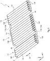
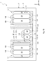
- the storage arrangement 1 shown for a vehicle for storing and releasing a compressed gas consists of several storage tubes 1.0, each of which is combined in groups to form a first storage tube section 1.1, a second storage tube section 1.2 and a third storage tube section 1.3, with the first and second storage tube sections 1.1 and 1.2 being connected via a fluid connection means 1.12 designed as a connecting tube 1.120, forming an intermediate space Z1, and the second and third tubular storage sections 1.2 and 1.3 are fluidly connected via a connecting tube 1.130 as a further fluid connecting means 1.13, forming an intermediate space Z2.
- Each of the three pipe storage sections 1.1, 1.2 and 1.3 consists of two layers L1 and L2 of pipe storage 1.0 and lie parallel to one another with respect to their longitudinal direction S in such a way as to save space so that adjacent pipe storage units from the lower layer L1 and the upper layer L2 are offset by 60° with respect to their longitudinal axis are, d. H. the circular circumference of a pipe store 1.0 lies tangentially to the circular circumferences of the pipe store 1.0 lying in the adjacent layer L1 or L2.
- the tube storage 1.0 of the tube storage sections 1.1, 1.2 and 1.3 are each fluidly connected at the same axial ends by means of tube storage loops 1.01 and 1.02, so that a meandering fluid path is created.
- the compressed gas is routed upwards, for example, from an input E of a tube store 1.0 in the lower layer L1 into a directly adjacent tube store 1.0 in the second layer L2 and then back down into a directly adjacent tube store 1.0 in the first layer, etc.
- the connecting pipe 1.12 connecting the two pipe storage sections 1.1 and 1.2 connects the same axial ends of the adjacent pipe storage 1.0 of the first and second pipe storage sections 1.1 and 1.2 in the first layer L1 and therefore runs horizontally in the plane formed by the first layer L1.
- the two pipe storage sections 1.2 and 1.3 are fluidly connected on the opposite side via the same axial ends of the adjacent pipe storage 1.0 of the second and third pipe storage sections 1.2 and 1.3 in the first layer L1 by means of the connecting pipe 1.13, which is also horizontal in the first layer L1 formed level runs.
- the spaces Z1 and Z2 created by the spaced tubular storage sections 1.1, 1.2 and 1.3 are used for the installation of cross members 2.1 and 2.2 to be connected to the structure of a vehicle body (cf. figure 2 ) used.
- the two crossbeams 2.1 and 2.2 are arranged in the spaces Z1 and Z2 in the plane formed by the second layer L2, i.e. they are aligned with the pipe stores 1.0 of the second plane L2, without crossing the area of the connecting pipes 1.12 and 1.13.
- the cross section of these crossbeams 2.1 and 2.2 is due to the distance b1 (cf.
- FIG 3 of the two pipe storage tanks 1.0 adjoining the intermediate space Z1 or Z2 in the second layer L2 and on the other hand to the diameter D (cf. figure 3 ) the pipe storage 1.0 adjusted so that the height of the crossbeams 2.1 and 2.2 does not exceed the pipe storage 1.0 of the second layer L2.
- the two crossbeams 2.1 and 2.2 in the storage arrangement 1 are shown figure 1 not shown.
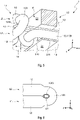
- FIG. 2.1 An alternative embodiment with regard to the cross-sectional shape of the cross members 2.1 and 2.2 shows figure 3 using the cross member 2.1.
- This crossbeam 2.1 also partially utilizes the space between the storage tube 1.0 connected to the connecting tube 1.12, since the diameter d1 of the connecting tube 1.12 is smaller than the diameter D of a storage tube 1.0.
- the cross member 2.1 to be adapted to this intermediate space Z1 with a T-shaped cross section, with the transverse section of the T shape being adapted to the distance b1 of the pipe store 1.0 of the second layer L2 adjoining the intermediate space Z1 and thus to the cross section of the cross member 2.1 after figure 2 corresponds, while the longitudinal section of the T-shape along the distance b2 between the tube store 1.0 of the first layer L1 adjoining the intermediate space Z1 is adapted to the edge of the connecting pipe 1.12 running in the direction of the pipe store 1.0 of the second layer L2.
- the distance between the pipe stores 1.0 between the pipe stores 1.0 of the first layer L1 is denoted by the reference symbol b3, where b3 ⁇ b2 applies.
- the figure 4 shows a memory arrangement 1 designed as an assembly with the figure 1 illustrated pipe storage 1.0.
- the tube accumulator 1.0 corresponding to those according to figure 1 also grouped at a distance into three tube storage sections 1.1, 1.2 and 1.3 to form the intermediate spaces Z1 and Z2.
- These intermediate spaces Z1 and Z2 are also bridged at the edge by a connecting pipe 1.12 and 1.13 aligned with the first layer for the fluid connection of the individual pipe storage sections 1.1, 1.2 and 1.3.
- This arrangement of the three spaced-apart pipe storage sections 1.1, 1.2 and 1.3 is framed by a frame support 3, which is essentially rectangular in shape with four frame elements 3.3, 3.4, 3.5 and 3.6.
- the frame support 3.3 is arranged on one side of the axial ends of the tube store 1.0 and the frame support 3.4 on the opposite side, while the frame supports 3.5 and 3.6 connecting the two frame elements 3.3 and 3.4 run in the longitudinal direction S of the tube store 1.0.
- This frame support 3 also includes a crossbar 3.1 and a crossbar 3.2, which are arranged in the space Z1 between the first and second tube storage section 1.1 and 1.2 or in the space Z2 between the second and third tube storage section 1.2 and 1.3 and the two frame elements 3.3 and 3.4 of the frame support 3 connect non-positively.
- the two transverse webs 3.1 and 3.2 run in the plane formed by the first layer L1 of the pipe storage 1.0, i.e. they are aligned with the pipe storage 1.0 of the first level L1 and therefore cross the connecting pipes 1.12 and 1.12 fluidly connecting the pipe storage sections 1.1, 1.2 and 1.3 1.13. Therefore, the area of the crossbar 3.1, where the connecting tube 1.12 is passed through, is provided with a cutout 3.10, as shown in FIG figure 5 is evident. As a result, the cross section of the transverse web 3.1 is reduced to a narrow web 3.11, which is non-positively connected to the frame element 3.4.
- the transverse web 3.1 is adapted in its cross section to the intermediate space Z1 between the adjacent pipe stores 1.0 of the first layer L1 in the first layer L1 such that their width is the distance b3 between these two pipe stores 1.0 and the height is slightly greater than the diameter D of the pipe stores 1.0 (cf. figure 3 ).
- the transverse web 3.1 thus protrudes only downwards by a projection a beyond the first layer L1, but does not protrude upwards in the direction of the tube storage 1.0 of the second layer L2 beyond the tube storage 1.0 of the first layer. In this direction upwards, the cross member 2.1 closes with a corresponding of figure 2 executed cross section. In this way, the cross bar 3.1 can be produced in one piece together with the cross member 2.1.
- the transverse web 3.2 arranged between the second tubular storage section 1.2 and the third raw storage section 1.3 is designed in a corresponding manner and has a cutout 3.20 for the passage of the connecting pipe 1.13.
- the cross section of this transverse web 3.2 is also adapted to the width b3 of the intermediate space Z2 transversely to the longitudinal direction S of the pipe storage 1.0 and is slightly larger than the diameter D of the pipe storage 1.0, so that the transverse web 3.2 does not go above the pipe storage in the direction of the second layer L2 1.0 of the first layer protrudes, but towers over the tube storage 1.0 of the first layer L1 downwards with a supernatant a.
- the frame support 3 is also designed relative to the three pipe storage sections 1.1, 1.2 and 1.3 in such a way that the frame elements 3.3 to 3.6, in adaptation to the two transverse webs 3.1 and 3.2, run in the plane of the first layer L1 of the pipe storage 1.0, i.e. not upwards the storage tubes 1.0 of the first layer L1 protrude, but project beyond the storage tubes 1.0 of the first layer L1 with the overhang a at the same height corresponding to the transverse webs 3.1 and 3.2.
- figure 5 is the in the figures 1 and 2 described crossbeam 2.1, which is aligned with the crossbar 3.1 in the intermediate space Z1 and at the height of the pipe storage 1.0 of the second layer L2, so that the crossbeam 2.1 is the pipe storage 1.0 of the second layer L2 upwards, i.e. in the opposite direction to the first layer L1 not towered over.
- this cross member is 2.1 and the cross member 2.2 according to figure 2 in the representation of the memory arrangement 1 after figure 4 not marked.
- the frame support 3 is non-positively connected to the cross members 2.1 and 2.2 via attachment points 3.0 of the two crosspieces 3.1 and 3.2.
- the storage arrangement 1 consisting of three tube storage sections 1.1, 1.2 and 1.3 together with the frame support 3, can be non-positively connected to the structure of the vehicle body not only via the cross members 2.1 and 2.2, but also the frame support 3 by means of on the frame elements 3.3, 3.4, 3.5 and 3.6 provided attachment points 3.0.
- the frame element 3.6 of the frame support 3 is after figure 4 not in a straight line, but with a slight bulge pointing outwards, so that an installation space Z3 for valves and a pressure control unit is created between the third tubular storage section 1.3 and the frame element 3.6.
- the frame support 3 after figure 4 has, in addition to the frame elements 3.1 to 3.6, a rod-shaped fastening carrier 4.1 running parallel to the frame element 3.4 and another rod-shaped fastening carrier 4.2 running parallel to the frame element 3.3, which are each connected at the ends with the frame elements 3.5 and 3.6 in a non-positive manner.
- the fastening support 4.1 is guided perpendicularly to the longitudinal direction S of the pipe storage 1.0 through the openings 1.010 of the pipe storage loops 1.01 located at the same axial end of the pipe storage 1.0, as is detailed in figure 6 is shown.
- the other fastening support 4.2 is passed through the openings 1.020 of the tube storage loops 1.02 on the opposite side.
- the cross section of these fastening supports 4.1 and 4.2 is in line with the contour of the openings 1.010 and 1.020 of the tube storage loops 1.01 and 1.02 as shown in the illustration figure 5 customized.
- these mounting brackets 4.1 and 4.2 run in the plane formed by the pipe stores 1.0 of the first layer L1, they must be guided through the transverse webs 3.1 and 3.2 and have corresponding cutouts for this purpose.
- the already existing cutouts 3.10 and 3.20 of the transverse webs 3.1 and 3.2 serve this purpose.
- Further cutouts 3.12 and 3.21 are provided at the opposite ends of the transverse webs for the passage of the fastening supports 4.1 and 4.2.
- the cutouts 3.10 and 3.12 in the crossbar 3.1 or the cutouts 3.20 and 3.21 in the crossbar 3.2 can each have the same end configuration.
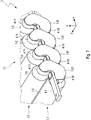
- the pipe storage loops 1.01 and 1.02 are non-positively connected to the mounting brackets 4.1 and 4.2 by means of mounting brackets 4.10 and 4.11 designed as pipe clamps, as is the case for the mounting bracket 4.1 in figure 7 is shown.
- the pipe storage loops 1.01 are each positively connected to the fastening support 4.1 with fastening straps 4.10 at their lower end connected to pipe storage 1.0 of the first layer L1 and on the other hand with fastening straps 4.11 to the fastening support 4.1 at their upper end connected to pipe storage 1.0 of the second layer L2 .
- the memory arrangement designed as an assembly figure 4 is connected to the structure of the body of the vehicle via the cross members 2.1 and 2.2 and thereby integrated into it, for example by the frame support 3 being non-positively connected to the underbody of the vehicle body via attachment points 3.0.
- a seal 3.7 for soundproofing can be provided on the frame elements 3.3 to 3.6 of the frame girder.
- the figure 8 shows a further embodiment of the storage arrangement 1 as an assembly for assembly and integration into a vehicle body.
- a mounting frame 2 with a structure congruent to the frame beam 3 is connected to this frame beam 3 .
- This mounting frame 2 includes in addition to the two cross members 2.1 and 2.2 according to the representations of Figures 2, 3 and 4 Support elements 2.3, 2.4, 2.5 and 2.6.
- This fastening frame 2 is placed with its support elements 2.3 to 2.6 on the frame support 3 in such a way that the individual support elements 2.3 to 2.6 lie congruently on the corresponding frame elements 3.3 to 3.6 of the frame support 3; this of course also applies to the two cross members 2.1 and 2.2 and the two crossbars 3.1 and 3.2.
- the mounting frame 2 is in the plane of the second layer L2 formed by the tube stores 1.0.
- the intermediate spaces formed by the carrier elements 2.3 to 2.6 and the crossbeams 2.1 and 2.2 are closed by means of cover elements 2.7, 2.8 and 2.9.
- the cover element 2.7 closes the area between the cross member 2.1 and the support element 2.5, the cover element 2.8 the area between the two cross members 2.1 and 2.2 and finally the cover element 2.9 the area between the cross member 2.2 and the support
- cover elements 2.70, 2.80 and 2.90 form a base plate with a sufficient distance to the storage tubes 1.0 of the first layer L1, since the frame support 3 together with the transverse webs 3.1 and 3.2 lower the storage tubes 1.0 of the first layer L1 downwards in the vertical direction of the vehicle (z-direction). the supernatant a (cf. figure 5 ) surmounted. This is the case when a force acts on the vehicle from below, ie on the storage arrangement 1 figure 8 there is sufficient deformation path to avoid damage to the storage tubes 1.0.
- the mounting frame 2 has mounting points 2.0, via which the storage arrangement 1 figure 7 are non-positively connected to carriers of the vehicle body.
- fastening frame 2 together with the frame support 3 in one piece.
- the memory arrangement 1 can figure 4 and so after figure 8 can also only be designed with two tubular storage sections 1.1 and 1.2, so that only one crossbeam 2.1 or only one crossbar 3.1 is required for the frame beam 3 or the mounting frame 2.
- This memory arrangement designed as an assembly 1 after figure 8 assumes a structural function in the vehicle in that this assembly can absorb high forces via the components 2.1 to 2.6 of the mounting frame 2, also via the transverse webs 3.1 and 3.2, both in the longitudinal direction of the vehicle (x-direction) and in the transverse direction of the vehicle (y-direction).
- FIG. 9 An alternative embodiment of the memory arrangement 1 after figure 8 is in the figures 9 and 10 shown, this storage arrangement 1 having only two storage tube sections, namely a first storage tube section 1.1 and a second storage tube section 1.2.
- this memory arrangement 1 consists of the two pipe storage sections 1.1 and 1.2 separating cross member 2.1 of the storage arrangement 1 after figure 8 from two partial cross members 2.10 and 2.11, which are arranged at a distance A from one another to form the intermediate space Z1 in the longitudinal direction of the vehicle (x-direction).
- the two partial crossbeams 2.10 and 2.11 also run in the plane of the second layer L2 of the tube storage 1.0 of the two tube storage sections 1.1 and 1.2 corresponding to the crossbeam 2.1 of the storage arrangement 1 figure 4 or figure 8 .
- the two tube storage sections 1.1 and 1.2 are fluidly connected by means of a fluid connection means 1.12 designed as a connecting tube 1.120, the length of the connecting tube 1.120 being adapted to the distance A so that the intermediate space Z1 is bridged.
- the storage arrangement 1 also has a transverse web 3.1, which consists of two partial transverse webs 3.13 and 3.14 running in the plane of the first layer L1 of the pipe storage 1.0 of the two pipe storage sections 1.1 and 1.2, each of which is connected to a partial cross member 2.10 and 2.11 in the vertical direction of the vehicle ( z-direction) are aligned.
- the connecting tube 1.120 runs in the first layer L1 of the tube store 1.0 of the two tube store sections 1.1 and 1.2 and breaks through the two partial transverse webs 3.13 and 3.14, which have corresponding cutouts 3.10.
- the frame support 3 can also be made in one piece with the mounting frame 2 and form a housing for the tube storage 1.0.
- this memory array 1 In an integration of this memory array 1 according to figures 9 and 10 In a vehicle, the area of the space Z1 between front seats and a rear seat bench of the vehicle is located and forms a foot garage 5 for the rear passengers to put their feet. In figure 9 the course of a passenger cell floor 6 of the vehicle is shown schematically, with the intermediate space Z1 forming the foot garage 5 .
- the pipe storage 1.0 of the two pipe storage sections 1.1 and 1.2 are each connected to pipe storage loops 1.01 and 1.02, with according to the figures 9 and 10 the pipe storage 1.0 of the first layer L1 and the second layer L2 are alternately connected, as indicated by the arrows P1 figure 9 is shown.
- the tube storage 1.0 of the respective tube storage sections 1.1 and 1.2 can also be fluidly connected in layers, as indicated by the arrows P2 (shown in broken lines) according to FIG figure 9 is shown.
- the intermediate space Z1 used as a footwell 5 according to the storage arrangement 1 figure 9 and 10 can also be used for arranging further pipe stores 1.0 in the plane of the first layer L1, resulting in a foot garage 5 with a smaller depth in the vertical direction of the vehicle.
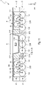
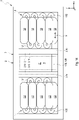
- FIG figures 11 and 12 Such a memory arrangement 1 is shown in FIG figures 11 and 12 , In which in the intermediate space Z1 an intermediate section 1.10 tube store with, for example, three tube stores 1.0 is arranged. These storage tubes 1.0 of the intermediate section 1.10 of the storage tube lie in the plane of the first layer L1 and are fluidly connected in a meandering manner by means of tube storage loops 1.01 and 1.02.
- first and second pipe storage sections 1.1 and 1.2 are each made up of two layers L1 and L2 of pipe storage systems 1.0 creates a foot garage 5 in the intermediate space Z1 due to the pipe storage systems 1.0 of the intermediate pipe storage section 1.10 being reduced by one layer compared to the pipe storage sections 1.1 and 1.2, such as this can be seen from the course of a schematically indicated passenger compartment floor 6 .
- the fluid connection of the intermediate storage tube section 1.10 with the adjacent storage tube sections 1.1 and 1.2 is effected by means of a fluid connection means 1.12 which, as a first connecting pipe section 1.121, fluidly connects the adjacent storage tubes 1.0 of the first storage pipe section 1.1 and of the intermediate storage pipe section 1.10 and which, as a second connecting pipe section 1.122, connects the adjacent storage pipes 1.0 of the second storage pipe section 1.2 and the pipe storage intermediate section 1.10 fluidly connects.
- the two connecting tube sections 1.121 and 1.122 are guided over cutouts 3.10 and 3.12 of the partial transverse webs 3.13 and 3.14.
- the pipe storage 1.0 of the two pipe storage sections 1.1 and 1.2 are each connected to pipe storage loops 1.01 and 1.02, according to the figures 11 and 12 the pipe storage 1.0 of the first layer L1 and the second layer L2 are alternately connected, as indicated by the arrows P1 figure 11 is shown.
- the tube storage 1.0 of the respective tube storage sections 1.1 and 1.2 can also be fluidly connected in layers, as shown by the arrows P2 (dashed line) according to FIG.
- the frame support 3 and the mounting frame 2 of the storage arrangement 1 with the partial transverse webs 3.13 and 3.14 and the partial transverse supports 2.10 and 2.11 are similar to those of the storage arrangement figure 9 and figure 10 constructed and form a housing for the pipe storage 1.0.
- the pipe storage sections 1.1 and 1.2 of the storage arrangement 1 according to figures 11 and 12 can of course also be formed with more than two layers of pipe storage 1.0.
- the pipe store intermediate section 1.10 is designed with a number of layers of pipe stores 1.0 reduced by at least the value 1.
- the memory arrangement 1 according to figures 11 and 12 can also be carried out without the first or second storage tube section 1.1 or 1.2, so that the storage arrangement 1 is produced from the intermediate storage tube section 1.10 as the first storage tube section with the foot garage 5 and another storage tube section as the second storage tube section 1.2.
- the figure 13 shows a memory arrangement 1 according to FIG figures 11 and 12 alternative storage arrangement 1 with an intermediate pipe storage section 1.10 also arranged in the intermediate space Z1 with, for example, two pipe storages 1.0.
- the difference to the memory arrangement 1 according to the figures 11 and 12 is that the two pipe storage 1.0 of the pipe storage intermediate section 1.10 in the longitudinal direction S, ie in the vehicle transverse direction (y-direction) with a length B shorter compared to the length b of the pipe storage 1.0 of the two pipe storage sections 1.1 and 1.2 are executed, so B ⁇ b applies.
- the foot garage 5.1 has a greater depth in the vertical direction of the vehicle than the foot garage 5.
- the pipe storage sections 1.1 and 1.2 can be formed with more than two layers of pipe storage 1.0.
- the pipe store intermediate section 1.10 then has at least a number of layers of pipe stores 1.0 reduced by the value 1.
- the memory arrangement 1 can figure 13 corresponding to the memory arrangement 1 according to the figures 11 and 12 also without the first and second tube storage section 1.1 or 1.2, so that the storage arrangement 1 is produced from the intermediate tube storage section 1.10 as the first pipe storage section with the foot garage 5 and 5.1 and another pipe storage section as the second pipe storage section 1.2.
- the figure 14 shows a memory arrangement 1 according to FIG figures 9 and 10 alternative memory arrangement 1, in which, in contrast to that according to figure 10 the pipe storage 1.0 of the first and second pipe storage sections 1.1 and 1.2 are aligned with their longitudinal direction S perpendicular to the partial cross members 2.10 and 2.11 and thus also perpendicular to the partial transverse webs 3.13 and 3.14, i.e. in the longitudinal direction of the vehicle (x-direction).
- the intermediate space Z1 remains free of pipe storage and forms a foot garage 5.
- the pipe storage 1.0 of the pipe storage sections 1.1 and 1.2 are connected in a meandering manner by means of pipe storage loops 1.01 and 1.02.
- the tube storage loops 1.01 and 1.02 connect respectively adjacent tube storage 1.0 of the first and second layer L1 and L2. It is of course also possible to connect the pipe storage 1.0 in layers in each case.
Description
Die Erfindung betrifft eine Speicheranordnung für ein Fahrzeug zum Speichern und Abgeben eines Druckgases gemäß dem Oberbegriff des Patentanspruchs 1. Die Erfindung betrifft ferner ein Fahrzeug mit einer Speicheranordnung zum Speichern und Abgeben eines Druckgases gemäß des Oberbegriffs des Patentanspruchs 8.The invention relates to a storage arrangement for a vehicle for storing and releasing a compressed gas according to the preamble of
Anordnungen zum Speichern von Gas unter hohem Druck sind aus dem allgemeinen Stand der Technik bekannt und dienen bspw. zum Speichern von Erdgas oder Wasserstoff. Solche Speicher haben einen vergleichsweise großen Durchmesser im Verhältnis zu ihrer Länge und sind deshalb wegen der damit verbundenen Bauhöhe hinsichtlich der Integration in eine Fahrzeugstruktur kritisch zu bewerten.Arrangements for storing gas under high pressure are known from the general prior art and are used, for example, to store natural gas or hydrogen. Such accumulators have a comparatively large diameter in relation to their length and are therefore to be viewed critically with regard to integration into a vehicle structure because of the associated overall height.
Daher werden mehrere sogenannte Rohrspeicher, die flaschenförmig mit einem kleinen Durchmesser im Verhältnis zur Länge ausgeführt sind, zu einem modularen Druckbehälter zusammengefasst, wie dies bspw. aus der
Eine gattungsbildende Speicheranordnung für ein Fahrzeug zum Speichern und Abgeben eines Druckgases ist aus der
Diese Speicheranordnung besteht aus mehreren übereinander angeordneten Rohrspeicher, wobei die nebeneinander angeordneten Rohrspeicher einer Lage an deren axialen Enden mittels Rohrspeicherschleifen fluidverbunden sind. Die am Rand zweier übereinander angeordneten Lagen benachbarten Rohrspeicher werden ebenso mittels solchen Rohrspeicherschleifen fluidverbunden. Um diese gestapelten Rohrspeicher zusammenzuhalten, werden quer zur Längsrichtung der Rohrspeicher verlaufende Montagewände mit an den Querschnitt der Rohrspeicher angepassten Montageöffnungen verwendet, wobei die Rohrspeicher in diese Montageöffnungen eingeführt und fixiert werden. Es wird auch vorgeschlagen, solche Montagewände jeweils im Bereich der Rohrspeicherschleifen einzusetzen, so dass die Rohrspeicherschleifen schleifenförmig durch zwei Montageöffnungen geführt werden. Solche Montagewände sind entlang der Montageöffnungen einer Lage geschlitzt ausgeführt, so dass mittels an den Stirnseiten verlaufenden Spannbändern diese Montagewände zusammengepresst und gleichzeitig eine Verbindung mit der Karosserie eines Fahrzeugs hergestellt wird.This storage arrangement consists of a plurality of storage tubes arranged one above the other, with the storage tubes of one layer arranged next to one another being fluidically connected at their axial ends by means of storage tube loops. The tube stores adjacent to the edge of two layers arranged one above the other are also fluidly connected by means of such tube store loops. In order to hold these stacked tube stores together, mounting walls running transversely to the longitudinal direction of the tube stores with mounting openings adapted to the cross section of the tube stores are used, with the tube stores being inserted and fixed in these mounting openings. It is also proposed to use such mounting walls in each case in the area of the pipe storage loops, so that the pipe storage loops are guided through two installation openings in the form of a loop. Such mounting walls are designed to be slotted along the mounting openings of a layer, so that these mounting walls are pressed together by means of clamping straps running on the end faces and at the same time a connection to the body of a vehicle is established.
Bei Fahrzeugen, die speziell für einen Elektroantrieb konfiguriert sind, befindet sich unterhalb des Fahrgastzellenbodens ein Technikraum für Traktionsbatterien des Elektroantriebs. Ein solches Fahrzeug ist bspw. aus der
Auch die
Der Erfindung liegt die Aufgabe zugrunde, eine Speicheranordnung aus mehreren Rohrspeichern zum Speichern und Abgeben eines Druckgases zu schaffen, die in die Karosseriestruktur des Fahrzeugs mit hoher Crashsicherheit integrierbar ist. Ferner ist es Aufgabe der Erfindung ein Fahrzeug mit einer Speicheranordnung aus mehreren Rohrspeichern zum Speichern und Abgeben eines Druckgases anzugeben, die in die Karosseriestruktur eines Fahrzeugs mit dem Ziel einer erhöhten Crashsicherheit integriert ist.The invention is based on the object of creating a storage arrangement made up of a plurality of pipe stores for storing and releasing a compressed gas, which can be integrated into the body structure of the vehicle with a high level of crash safety. Furthermore, the object of the invention is to specify a vehicle with a storage arrangement made up of a plurality of tube storage devices for storing and releasing a compressed gas, which is integrated into the body structure of a vehicle with the aim of increased crash safety.
Die erstgenannte Aufgabe wird gelöst durch eine Speicheranordnung mit den Merkmalen des Patentanspruches 1.The first-mentioned object is achieved by a memory arrangement having the features of
Eine solche Speicheranordnung für ein Fahrzeug zum Speichern und Abgeben eines Druckgases umfasst:
- einen ersten Rohrspeicherabschnitt mit mehreren in einer ersten Lage und wenigstens in einer zweiten Lage längsparallel zueinander angeordneten Rohrspeicher, die an deren axialen Enden mittels Rohrspeicherschleifen mäanderförmig fluidverbunden sind,
- wenigstens einen zweiten Rohrspeicherabschnitt mit mehreren in einer ersten Lage und wenigstens in einer zweiten Lage längsparallel zueinander angeordneten Rohrspeicher, die an deren axialen Enden mittels Rohrspeicherschleifen mäanderförmig fluidverbunden sind, und
- einem Fluidverbindungsmittel zum Fluidverbinden des ersten und zweiten Rohrspeicherabschnittes.
- a first tube storage section with a plurality of tube storages arranged longitudinally parallel to one another in a first layer and at least in a second layer, which are fluidly connected at their axial ends by means of tube storage loops in a meandering manner,
- at least one second storage tube section with a plurality of storage tubes arranged longitudinally parallel to one another in a first layer and at least in a second layer, which are fluidly connected at their axial ends by means of tube storage loops in a meandering manner, and
- fluid connection means for fluidly connecting the first and second storage tube sections.
Erfindungsgemäß ist vorgesehen, dass
- das Fluidverbindungsmittel die jeweils gleichen axialen Enden von zwei entweder in der ersten Lage auf einer Ebene benachbarten Rohrspeicher oder in der zweiten Lage auf einer Ebene benachbarten Rohrspeicher fluidverbindet, und
- ein Zwischenraum zwischen dem ersten und zweiten Rohrspeicherabschnitt zur Aufnahme eines Querträgers der Karosserie des Fahrzeugs, welcher entweder mit der zweite Lage der Rohrspeicher fluchtet, wenn das Fluidverbindungsmittel mit der ersten Lage der Rohrspeicher fluchtet, oder mit der ersten Lage der Rohrspeicher fluchtet, wenn das Fluidverbindungsmittel mit der zweiten Lage der Rohrspeicher fluchtet.
- the fluid connection means fluidly connects the respective same axial ends of two accumulators either adjacent on a plane in the first tier or adjacent on a plane in the second tier, and
- a space between the first and second storage tube sections for receiving a cross member of the body of the vehicle which is aligned with either the second layer of storage tubes when the fluid connection means is aligned with the first layer of storage tubes, or with the first layer of storage tubes is aligned when the fluid connection means is aligned with the second layer of storage tubes.
Bei einer solchen Speicheranordnung mit mindestens zwei beabstandeten Rohrspeicherabschnitte werden diese derart miteinander fluidverbunden, dass in dem Zwischenraum zwischen den beiden Rohrspeicherabschnitten ein Querträger hindurchgeführt werden kann, ohne dass dieser für das die beiden Rohrspeicherabschnitte verbindende vorzugsweise als Verbindungsrohr ausgebildete Fluidverbindungsmittel freigeschnitten werden muss, da dieser mit derjenigen Lage der Rohrspeicher fluchtet bzw. eine gemeinsame Ebene bildet, in welcher das Fluidverbindungsmittel nicht verläuft.In such a storage arrangement with at least two spaced-apart storage tube sections, these are fluidly connected to one another in such a way that a cross member can be guided through the space between the two storage tube sections without having to cut it free for the fluid connection means, which is preferably designed as a connecting pipe, connecting the two storage tube sections, since this that position of the pipe storage is aligned or forms a common plane in which the fluid connection means does not run.
Weiterbildungsgemäß weist die Speicheranordnung einen den ersten Rohrspeicherabschnitt und den zweiten Rohrspeicherabschnitt umrahmenden Rahmenträger auf.According to a development, the storage arrangement has a frame support framing the first pipe storage section and the second pipe storage section.
Mit einem solchen Rahmenträger und den mindestens zwei Rohrspeicherabschnitten wird eine eigenständige herstellbar Baugruppe geschaffen. Vorzugsweise wird die mechanische Verbindung zwischen den beiden Rohrspeicherabschnitten und dem Rahmenträger dadurch hergestellt, dass zwischen dem ersten und zweiten Rohrspeicherabschnitt ein Quersteg angeordnet ist, welcher mit derjenigen ersten oder zweiten Lage der Rohrspeicher fluchtet, mit der auch das vorzugsweise als Verbindungsrohr ausgebildete Fluidverbindungsmittel fluchtet, wobei das Verbindungsrohr als Fluidverbindungsmittel durch den Quersteg geführt ist. Der Quersteg ist endseitig mit dem Rahmenträger kraftschlüssig verbunden.An assembly that can be produced independently is created with such a frame support and the at least two pipe storage sections. The mechanical connection between the two tube storage sections and the frame support is preferably established in that a transverse web is arranged between the first and second tube storage section, which is aligned with that first or second layer of the tube storage with which the fluid connection means, which is preferably designed as a connecting tube, is also aligned, wherein the connecting tube is guided through the crossbar as a fluid connection means. The end of the crossbar is non-positively connected to the frame support.
Die Steifigkeit einer solchen Baugruppe kann weiter verbessert werden, wenn weiterbildungsgemäß die Speicheranordnung wenigstens einen stangenförmigen Befestigungsträger aufweist, welcher durch die Öffnungen der jeweils an einem gleichen axialen Ende der Rohrspeicher liegenden Rohrspeicherschleifen geführt und mit dem Rahmenträger kraftschlüssig verbunden ist. Es ist natürlich auch möglich auf der gegenüberliegenden Seite einen weiteren Befestigungsträger durch die Rohrspeicherschleifen zu führen.The rigidity of such an assembly can be further improved if, according to a further development, the storage arrangement has at least one rod-shaped fastening support which is guided through the openings of the pipe storage loops located at the same axial end of the pipe storage and is non-positively connected to the frame support. Of course, it is also possible to run another fastening support through the pipe storage loops on the opposite side.
Weiterhin ist nach einer bevorzugten Weiterbildung der Erfindung in dem Zwischenraum zwischen dem ersten und zweiten Rohrspeicherabschnitt ein Rohrspeicherzwischenabschnitt mit mehreren längsparallel in wenigstens der ersten Lage angeordneten Rohrspeicher vorgesehen, die an deren axialen Enden mittels Rohrspeicherschleifen mäanderförmig fluidverbunden sind. Hierbei ist die Anzahl der Lagen der Rohrspeicher des Rohrspeicherzwischenabschnittes um wenigstens eine Lage gegenüber der Anzahl der Lagen der Rohrspeicher des ersten und/oder zweiten Rohrspeicherabschnittes kleiner, wobei das in der ersten Lage der Rohrspeicher verlaufende Fluidverbindungsmittel aus einem die benachbarten Rohrspeicher des ersten Rohrspeicherabschnittes und des Rohrspeicherzwischenabschnittes fluidverbindenden ersten Verbindungsrohrabschnitt und einem die benachbarten Rohrspeicher des zweiten Rohrspeicherabschnittes und des Rohrspeicherzwischenabschnittes fluidverbindenden zweiten Verbindungsrohrabschnitt besteht.Furthermore, according to a preferred development of the invention, in the space between the first and second tube storage section, an intermediate tube storage section is provided with several longitudinally parallel storage tubes arranged in at least the first layer, which are fluidly connected in a meandering manner at their axial ends by means of pipe storage loops. In this case, the number of layers of the tube stores of the intermediate tube store section is at least one layer smaller than the number of layers of the tube stores of the first and/or second tube store section, with the fluid connection means running in the first layer of the tube stores consisting of one connecting the adjacent tube stores of the first tube store section and of the Pipe storage intermediate section fluid-connecting first connecting pipe section and the adjacent pipe storage of the second pipe storage section and the pipe storage intermediate section fluid-connecting second connecting pipe section.
Dadurch dass der Rohrspeicherzwischenabschnitt zwischen dem ersten und zweiten Rohrspeicherabschnitt mit weniger Lagen von Rohrspeichern als die benachbarten Rohrspeicherabschnitte ausgebildet ist, bildet dieser Rohrspeicherabschnitt eine Fußgarage für die Ablage der Füße von Fondpassagieren.Because the intermediate tube section between the first and second tube storage sections is formed with fewer layers of tube storage than the adjacent tube storage sections, this tube storage section forms a foot garage for resting the feet of rear passengers.
Besonders vorteilhaft ist es hierbei, wenn die Rohrspeicher des Rohrspeicherzwischenabschnittes in deren Längsrichtung gegenüber den Rohrspeichern des ersten und/oder zweiten Rohrspeicherabschnittes verkürzt sind, wodurch in demjenigen Bereich des Zwischenraums zwischen den benachbarten Rohrspeicherabschnitten ohne Rohrspeicher eine in Fahrzeughochrichtung eines Fahrzeugs gesehen tiefere Fußgarage entsteht.It is particularly advantageous here if the tube stores of the intermediate tube store section are shortened in their longitudinal direction compared to the tube stores of the first and/or second tube store section, as a result of which a lower foot garage is created in that region of the gap between the adjacent tube store sections without a tube store, as seen in the vertical direction of a vehicle.
Die erfindungsgemäße Speicheranordnung kann auch mit mehr als zwei Rohrspeicherabschnitten aufgebaut werden, wobei zwischen jeweils zwei Rohrspeicherabschnitte Freiräume bestehen, die Querträger und/oder Querstege der oben beschriebenen Art aufnehmen.The storage arrangement according to the invention can also be constructed with more than two tubular storage sections, with free spaces between each two tubular storage sections that accommodate cross members and/or crossbars of the type described above.
Ferner ist es möglich, die Rohrspeicherabschnitte nicht nur aus zwei Lagen sondern auch aus drei oder mehr Lagen aufzubauen.Furthermore, it is possible to construct the tube storage sections not only from two layers but also from three or more layers.
Die Rohrspeicher der benachbarten Lagen liegen derart bauraumsparend aufeinander, dass benachbarte Rohrspeicher aus benachbarten Lagen bezüglich deren Längsachse um 60° versetzt sind, d. h. der kreisförmige Umfang eines Rohrspeicher liegt tangential an den kreisförmigen Umfängen der in der benachbarten Lage liegenden Rohrspeicher. Es ist natürlich auch möglich, die Rohrspeicher in anderer Weise aufeinander zu lagern.The storage tubes of the adjacent layers lie one on top of the other in such a way that saves space, that adjacent storage tubes from adjacent layers are offset by 60° with respect to their longitudinal axis, i. H. the circular perimeter of one storage tube is tangent to the circular perimeters of the storage tubes lying in the adjacent tier. Of course, it is also possible to store the tube storage on top of one another in a different way.
Die zweitgenannte Aufgabe wird gelöst durch ein Fahrzeug mit den Merkmalen des Patentanspruchs 8
- Ein solches Fahrzeug umfasst
- eine erfindungsgemäße Speicheranordnung zum Speichern und Abgeben eines Druckgases mit folgende Komponenten:
- einen ersten Rohrspeicherabschnitt mit mehreren in einer ersten Lage und wenigstens in einer zweiten Lage längsparallel zueinander angeordneten Rohrspeicher, die an deren axialen Enden mittels Rohrspeicherschleifen mäanderförmig fluidverbunden sind,
- wenigstens einen zweiten Rohrspeicherabschnitt mit mehreren in einer ersten Lage und wenigstens in einer zweiten Lage längsparallel zueinander angeordneten Rohrspeicher, die an deren axialen Enden mittels Rohrspeicherschleifen mäanderförmig fluidverbunden sind, und
- ein Fluidverbindungsmittel zum Fluidverbinden des ersten und zweiten Rohrspeicherabschnittes, und
- einen mit der Karosserie des Fahrzeugs kraftschlüssig verbundener Querträger.
- eine erfindungsgemäße Speicheranordnung zum Speichern und Abgeben eines Druckgases mit folgende Komponenten:
- Erfindungsgemäß ist vorgesehen, dass
- das Fluidverbindungsmittel die jeweils gleichen axialen Enden von zwei entweder in der ersten Lage benachbarten Rohrspeicher oder in der zweiten Lage benachbarten Rohrspeicher fluidverbindet, und
- der Querträger in einem Zwischenraum zwischen dem ersten und zweiten Rohrspeicherabschnitt entweder fluchtend mit der zweite Lage der Rohrspeicher, wenn das Verbindungsrohr mit der ersten Lage der Rohrspeicher fluchtet, oder fluchtend mit der ersten Lage der Rohrspeicher, wenn das Verbindungsrohr mit der zweiten Lage der Rohrspeicher fluchtet, angeordnet ist.
- Such a vehicle includes
- a storage arrangement according to the invention for storing and releasing a compressed gas with the following components:
- a first tube storage section with a plurality of tube storages arranged longitudinally parallel to one another in a first layer and at least in a second layer, which are fluidly connected at their axial ends by means of tube storage loops in a meandering manner,
- at least one second storage tube section with a plurality of storage tubes arranged longitudinally parallel to one another in a first layer and at least in a second layer, which are fluidly connected at their axial ends by means of tube storage loops in a meandering manner, and
- fluid connection means for fluidly connecting the first and second storage tube sections, and
- a crossmember frictionally connected to the body of the vehicle.
- a storage arrangement according to the invention for storing and releasing a compressed gas with the following components:
- According to the invention it is provided that
- the fluid connection means fluidly connects the respective same axial ends of two adjacent storage tubes either in the first layer or in the second layer, and
- the cross member in a space between the first and second tube storage sections either aligned with the second layer of tube storage when the connecting tube is aligned with the first layer of tube storage, or aligned with the first layer of tube storage when the connecting tube is aligned with the second layer of tube storage , is arranged.
Bei diesem Fahrzeug mit integrierter Speicheranordnung wird eine über die Karosseriestruktur ermöglichte Querabstützung realisiert, ohne dass die Speicheranordnung aus mehreren Rohrspeicher so unterbrochen werden muss, dass kein durchgehendes Speichervolumen entsteht. Hierzu werden mindestens zwei beabstandete Rohrspeicherabschnitte derart miteinander fluidverbunden, dass in dem Zwischenraum zwischen den beiden Rohrspeicherabschnitten ein Querträger hindurchgeführt werden kann, ohne dass dieser für das die beiden Rohrspeicherabschnitte verbindende vorzugsweise als Verbindungsrohr ausgebildeten Fluidverbindungsmittel freigeschnitten werden muss, da dieses mit derjenigen Lage der Rohrspeicher fluchtet bzw. eine gemeinsame Ebene bildet, in welcher das Fluidverbindungsmittel nicht verläuft.In this vehicle with an integrated storage arrangement, a transverse support made possible by the body structure is realized without the storage arrangement consisting of a plurality of tube storage systems having to be interrupted in such a way that no continuous storage volume is created. For this purpose, at least two spaced-apart tube storage sections are fluidly connected to one another in such a way that a cross member can be passed through in the space between the two tube storage sections without having to cut it free for the fluid connection means connecting the two tube storage sections, which is preferably designed as a connecting pipe, since this is aligned with that position of the pipe storage or forms a common plane in which the fluid connection means does not run.
Nach einer bevorzugten Weiterbildung der Erfindung umfasst die Speicheranordnung einen zwischen dem ersten und zweiten Rohrspeicherabschnitt angeordneten Quersteg, welcher mit derjenigen ersten oder zweiten Lage fluchtet, mit der auch das vorzugsweise als Verbindungsrohr ausgebildete Fluidverbindungsmittel fluchtet, wobei das den ersten mit dem zweiten Rohrspeicherabschnitt fluidverbindende Fluidverbindungsmittel durch den Quersteg geführt ist. Damit ist dieser Quersteg zwischen den beiden Rohrspeicherabschnitte so angeordnet, dass dieser für das Fluidverbindungsmittel an einem Endbereich des Querstegs freigeschnitten ist. Vorzugsweise wird die Speicheranordnung aus dem ersten und zweiten Rohrspeicherabschnitt von einem Rahmenträger umrahmt, so dass der Quersteg endseitig mit dem Rahmenträger kraftschlüssig verbindbar ist. Damit kann eine solche Speicheranordnung aus den beiden Rohrspeicherabschnitten und dem Rahmenträger als eigene Baugruppe hergestellt werden, die als solche mittels des Rahmenträgers mit der Struktur der Karosserie des Fahrzeugs kraftschlüssig verbindbar ist. Eine solche Baugruppe erhöht auch die Steifigkeit der Fahrzeugkarosserie.According to a preferred development of the invention, the storage arrangement comprises a transverse web arranged between the first and second tubular storage section, which is aligned with the first or second layer with which the fluid connection means, which is preferably designed as a connecting tube, is also aligned, with the fluid connection means fluidly connecting the first and second tubular storage section through the crossbar is guided. This transverse web is thus arranged between the two tube storage sections in such a way that it is cut free for the fluid connection means at an end region of the transverse web. Preferably, the storage arrangement consisting of the first and second tube storage sections is framed by a frame support, so that the end of the transverse web can be connected to the frame support in a non-positive manner. In this way, such a storage arrangement can be produced from the two tubular storage sections and the frame support as a separate assembly, which as such is non-positively connected to the structure of the vehicle body by means of the frame support is connectable. Such an assembly also increases the rigidity of the vehicle body.
Eine verbesserte mechanische Anbindung der beiden Rohrspeicherabschnitte an den Rahmenträger wird dadurch erzielt, dass wenigstens ein stangenförmiger Befestigungsträger durch die Öffnungen der an einem gleichen axialen Ende der Rohrspeicher liegenden Rohrspeicherschleifen geführt ist. Ein solcher Befestigungsträger ist mit dem Rahmenträger endseitig kraftschlüssig verbindbar. Mittels Befestigungslaschen können die Rohrspeicherschleifen mit dem Rahmenträger verbunden werden, um die Steifigkeit der Struktur aus den beiden Rohrspeicherabschnitte und dem Rahmenträger zu erhöhen.An improved mechanical connection of the two pipe storage sections to the frame support is achieved in that at least one rod-shaped fastening support is guided through the openings of the pipe storage loops located at the same axial end of the pipe storage. Such a mounting bracket can be non-positively connected at the end to the frame bracket. The pipe storage loops can be connected to the frame support by means of fastening straps in order to increase the rigidity of the structure made up of the two pipe storage sections and the frame support.
Eine weitere Baugruppe mit den beiden Rohrspeicherabschnitten ist weiterbildungsgemäß dadurch realisierbar, dass der Querträger zusammen mit Trägerelementen einen zum Rahmenträger kongruenten Befestigungsrahmen bildet, wobei die von dem Querträger und dem Trägerelement gebildete Zwischenräume mittels Deckelelementen und/oder die von den Rahmenelementen und dem Quersteg des Rahmenträgers gebildeten Zwischenräume mittels Deckelelementen verschlossen sind und der Befestigungsrahmen mit dem Rahmenträger kraftschlüssig verbunden ist oder einstückig hergestellt ist. Eine solche Baugruppe kann direkt bspw. an den Unterboden der Fahrzeugkarosserie montiert werden.A further assembly with the two pipe storage sections can be implemented according to a further development in that the cross member together with support elements forms a fastening frame congruent to the frame support, with the intermediate spaces formed by the cross member and the support element being closed by means of cover elements and/or those formed by the frame elements and the crossbar of the frame support Gaps are closed by means of cover elements and the mounting frame is non-positively connected to the frame support or is made in one piece. Such an assembly can be mounted directly, for example, on the underbody of the vehicle body.
Weiterhin ist nach einer bevorzugten Weiterbildung der Erfindung in dem Zwischenraum zwischen dem ersten und zweiten Rohrspeicherabschnitt ein Rohrspeicherzwischenabschnitt mit mehreren längsparallel in wenigstens der ersten Lage angeordneten Rohrspeicher vorgesehen, die an deren axialen Enden mittels Rohrspeicherschleifen mäanderförmig fluidverbunden sind. Hierbei ist die Anzahl der Lagen der Rohrspeicher des Rohrspeicherzwischenabschnittes um wenigstens eine Lage gegenüber der Anzahl der Lagen der Rohrspeicher des ersten und/oder zweiten Rohrspeicherabschnittes kleiner, wobei das in der ersten Lage der Rohrspeicher verlaufende Fluidverbindungsmittel aus einem die benachbarten Rohrspeicher des ersten Rohrspeicherabschnittes und des Rohrspeicherzwischenabschnittes fluidverbindenden ersten Verbindungsrohrabschnitt und einem die benachbarten Rohrspeicher des zweiten Rohrspeicherabschnittes und des Rohrspeicherzwischenabschnittes fluidverbindenden zweiten Verbindungsrohrabschnitt besteht.Furthermore, according to a preferred development of the invention, in the space between the first and second tube storage section, an intermediate tube storage section is provided with several longitudinally parallel storage tubes arranged in at least the first layer, which are fluidly connected in a meandering manner at their axial ends by means of pipe storage loops. In this case, the number of layers of the tube store of the intermediate tube store section is at least one layer smaller than the number of layers of the tube store of the first and/or second tube store section, with the fluid connection means running in the first layer of the tube store from one connecting the adjacent tube store of the first Pipe storage section and the pipe storage intermediate section fluid-connecting first connecting pipe section and the adjacent pipe storage of the second pipe storage section and the pipe storage intermediate section fluid-connecting second connecting pipe section.
Dadurch dass der Rohrspeicherzwischenabschnitt zwischen dem ersten und zweiten Rohrspeicherabschnitt mit weniger Lagen von Rohrspeichern als die benachbarten Rohrspeicherabschnitte ausgebildet ist, bildet dieser Rohrspeicherabschnitt eine Fußgarage für die Ablage der Füße von Fondpassagieren.Because the intermediate tube section between the first and second tube storage sections is formed with fewer layers of tube storage than the adjacent tube storage sections, this tube storage section forms a foot garage for resting the feet of rear passengers.
Besonders vorteilhaft ist es hierbei, wenn die Rohrspeicher des Rohrspeicherzwischenabschnittes in deren Längsrichtung gegenüber den Rohrspeichern des ersten und/oder zweiten Rohrspeicherabschnittes verkürzt ist, wodurch in demjenigen Bereich des Zwischenraums zwischen den benachbarten Rohrspeicherabschnitten ohne Rohrspeicher eine in Fahrzeughochrichtung gesehen weitere, jedoch tiefere Fußgarage entsteht.It is particularly advantageous here if the tube store of the intermediate tube store section is shortened in its longitudinal direction compared to the tube store of the first and/or second tube store section, as a result of which in that area of the intermediate space between the adjacent tube store sections without a tube store, a further but deeper foot garage is created when viewed in the vertical direction of the vehicle.
Die Rohrspeicher können mit der Längsrichtung in Fahrzeugquerrichtung oder in Fahrzeuglängsrichtung ausgerichtet werden.The tube storage can be aligned with the longitudinal direction in the vehicle transverse direction or in the vehicle longitudinal direction.
Weitere Vorteile, Merkmale und Einzelheiten der Erfindung ergeben sich aus der nachfolgenden Beschreibung bevorzugter Ausführungsformen sowie anhand der Zeichnungen. Dabei zeigen:
Figur 1- eine Speicheranordnung aus Rohrspeichern mit drei verbundenen Rohrspeicherabschnitten,
Figur 2- eine Seitenansicht auf die
Speicheranordnung nach Figur 1 mit Querträgern, Figur 3- eine Detaildarstellung der Speicheranordnung nach
Figur 2 mit einem alternativen Querträger, - Figur 4
- eine als Baugruppe aufgebaute Speicheranordnung,
Figur 5- eine Detaildarstellung der Baugruppe nach
Figur 4 mit einem Querträger, Figur 6- eine Detaildarstellung von über eine Rohrspeicherschleife verbundenen Rohrspeichern,
- Figur 7
- eine Detaildarstellung mehrerer über Rohrspeicherschleifen verbundenen Rohrspeichern eines Rohrspeicherabschnittes,
- Figur 8
- eine Speicheranordnung nach
Figur 4 mit einem Befestigungsrahmen, - Figur 9
- eine Speicheranordnung nach
Figur 8 in einer alternativen Ausführung mit einer Fußgarage in einer Schnittansicht gemäß Schnitt IX-IX nach Figur 10 , Figur 10- eine Speicheranordnung nach
Figur 9 in einer Draufsicht, - Figur 11
- eine Speicheranordnung nach
Figur 9 in einer alternativen Ausführung in einer Schnittansicht gemäß Schnitt IX-IX nachFigur 12 , - Figur 12
- eine Speicheranordnung nach
Figur 11 in einer Draufsicht, - Figur 13
- eine Speicheranordnung nach
Figur 12 in einer alternativen Ausführung in einer Draufsicht, und - Figur 14
- eine Speicheranordnung nach
Figur 10 in einer alternativen Ausführung.
- figure 1
- a storage arrangement of storage tubes with three connected storage tube sections,
- figure 2
- a side view of the storage arrangement
figure 1 with crossbeams, - figure 3
- a detailed representation of the memory arrangement
figure 2 with an alternative cross member, - figure 4
- a memory arrangement constructed as an assembly,
- figure 5
- a detailed view of the assembly
figure 4 with a cross member, - figure 6
- a detailed representation of pipe storage tanks connected via a pipe storage loop,
- figure 7
- a detailed representation of several pipe storages of a pipe storage section connected via pipe storage loops,
- figure 8
- a storage arrangement
figure 4 with a mounting frame, - figure 9
- a storage arrangement
figure 8 in an alternative embodiment with a foot garage in a sectional view according to section IX-IXfigure 10 , - figure 10
- a storage arrangement
figure 9 in a top view, - figure 11
- a storage arrangement
figure 9 in an alternative embodiment in a sectional view according to section IX-IXfigure 12 , - figure 12
- a storage arrangement
figure 11 in a top view, - figure 13
- a storage arrangement
figure 12 in an alternative embodiment in a plan view, and - figure 14
- a storage arrangement
figure 10 in an alternative version.
Die in den
Jeder der drei Rohrspeicherabschnitte 1.1, 1.2 und 1.3 besteht aus zwei Lagen L1 und L2 von Rohrspeichern 1.0 und liegen bezüglich ihrer Längsrichtung S parallel derart bauraumsparend aufeinander, dass benachbarte Rohrspeicher aus der unteren Lage L1 und der oberen Lage L2 bezüglich deren Längsachse um 60° versetzt sind, d. h. der kreisförmige Umfang eines Rohrspeicher 1.0 liegt tangential an den kreisförmigen Umfängen der in der benachbarten Lage L1 oder L2 liegenden Rohrspeicher 1.0.Each of the three pipe storage sections 1.1, 1.2 and 1.3 consists of two layers L1 and L2 of pipe storage 1.0 and lie parallel to one another with respect to their longitudinal direction S in such a way as to save space so that adjacent pipe storage units from the lower layer L1 and the upper layer L2 are offset by 60° with respect to their longitudinal axis are, d. H. the circular circumference of a pipe store 1.0 lies tangentially to the circular circumferences of the pipe store 1.0 lying in the adjacent layer L1 or L2.
Die Rohrspeicher 1.0 der Rohrspeicherabschnitte 1.1, 1.2 und 1.3 sind jeweils an den gleichen axialen Enden mittels Rohrspeicherschleifen 1.01 bzw. 1.02 fluidverbunden, so dass ein mäanderförmiger Fluidverlauf entsteht. Hierbei wird das Druckgas bspw. von einem Eingang E eines Rohrspeichers 1.0 der unteren Lage L1 in einen direkt benachbarten Rohrspeicher 1.0 der zweiten Lage L2 nach oben und anschließend wieder in einen direkt benachbarten Rohrspeicher 1.0 der ersten Lage nach unten usw. geleitet.The tube storage 1.0 of the tube storage sections 1.1, 1.2 and 1.3 are each fluidly connected at the same axial ends by means of tube storage loops 1.01 and 1.02, so that a meandering fluid path is created. In this case, the compressed gas is routed upwards, for example, from an input E of a tube store 1.0 in the lower layer L1 into a directly adjacent tube store 1.0 in the second layer L2 and then back down into a directly adjacent tube store 1.0 in the first layer, etc.
Das die beiden Rohrspeicherabschnitte 1.1 und 1.2 verbindende Verbindungsrohr 1.12 verbindet jeweils die gleichen axialen Enden der in der ersten Lage L1 der benachbarten Rohrspeicher 1.0 des ersten und zweiten Rohrspeicherabschnittes 1.1 und 1.2 und verläuft daher waagrecht in der von der ersten Lage L1 gebildeten Ebene.The connecting pipe 1.12 connecting the two pipe storage sections 1.1 and 1.2 connects the same axial ends of the adjacent pipe storage 1.0 of the first and second pipe storage sections 1.1 and 1.2 in the first layer L1 and therefore runs horizontally in the plane formed by the first layer L1.
Die beiden Rohrspeicherabschnitte 1.2 und 1.3 werden auf der gegenüberliegenden Seite über die jeweils gleichen axialen Enden der in der ersten Lage L1 der benachbarten Rohrspeicher 1.0 des zweiten und dritten Rohrspeicherabschnittes 1.2 und 1.3 mittels des Verbindungsrohrs 1.13 fluidverbunden, welches ebenso waagrecht in der von der ersten Lage L1 gebildeten Ebene verläuft.The two pipe storage sections 1.2 and 1.3 are fluidly connected on the opposite side via the same axial ends of the adjacent pipe storage 1.0 of the second and third pipe storage sections 1.2 and 1.3 in the first layer L1 by means of the connecting pipe 1.13, which is also horizontal in the first layer L1 formed level runs.
Die durch die beabstandeten Rohrspeicherabschnitte 1.1, 1.2 und 1.3 geschaffenen Zwischenräume Z1 und Z2 werden für die Installation von mit der Struktur einer Fahrzeugkarosserie zu verbindenden Querträgern 2.1 und 2.2 (vgl.
Eine alternative Ausführung hinsichtlich der Querschnittsform der Querträger 2.1 und 2.2 zeigt
Die
Diese Anordnung der drei beabstandeten Rohrspeicherabschnitte 1.1, 1.2 und 1.3 werden von einem Rahmenträger 3 umrahmt, welcher im wesentlichen rechteckförmig mit vier Rahmenelementen 3.3, 3.4, 3.5 und 3.6 ausgebildet ist. Hierbei ist auf der einen Seite der axialen Enden der Rohrspeicher 1.0 der Rahmenträger 3.3 und auf der gegenüberliegenden Seite der Rahmenträger 3.4 angeordnet, während in Längsrichtung S der Rohrspeicher 1.0 die die beiden Rahmenelemente 3.3 und 3.4 verbindenden Rahmenträger 3.5 und 3.6 verlaufen.This arrangement of the three spaced-apart pipe storage sections 1.1, 1.2 and 1.3 is framed by a
Dieser Rahmenträger 3 umfasst ferner einen Quersteg 3.1 und einen Quersteg 3.2, die in dem Zwischenraum Z1 zwischen dem ersten und zweiten Rohrspeicherabschnitt 1.1 und 1.2 bzw. in dem Zwischenraum Z2 zwischen dem zweiten und dritten Rohrspeicherabschnitt 1.2 und 1.3 angeordnet sind und die beiden Rahmenelemente 3.3 und 3.4 des Rahmenträgers 3 kraftschlüssig verbinden.This
Hierbei verlaufen die beiden Querstege 3.1 und 3.2 in der von der ersten Lage L1 der Rohrspeicher 1.0 gebildeten Ebene, fluchten also mit den Rohrspeichern 1.0 der ersten Ebene L1 und kreuzen daher die die Rohrspeicherabschnitte 1.1, 1.2 und 1.3 fluidverbindenden Verbindungsrohre 1.12 und 1.13. Daher ist der Bereich des Quersteges 3.1, wo das Verbindungsrohr 1.12 hindurchgeführt wird, mit einem Ausschnitt 3.10 versehen, wie dies aus
Der Quersteg 3.1 ist in seinem Querschnitt an den Zwischenraum Z1 zwischen den in der ersten Lage L1 benachbarten Rohrspeichern 1.0 der ersten Lage L1 so angepasst, dass deren Breite dem Abstand b3 dieser beiden Rohrspeicher 1.0 und die Höhe geringfügig größer ist als der Durchmesser D der Rohrspeicher 1.0 (vgl.
Wird ein Querträger 2.1 mit einem gemäß von
In entsprechender Weise ist auch der zwischen dem zweiten Rohrspeicherabschnitt 1.2 und dem dritten Rohspeicherabschnitt 1.3 angeordnete Quersteg 3.2 ausgeführt und weist einen Ausschnitt 3.20 zur Durchführung des Verbindungsrohres 1.13 auf. Auch der Querschnitt dieses Quersteges 3.2 ist an die Breite b3 des Zwischenraums Z2 quer zur Längsrichtung S der Rohrspeicher 1.0 angepasst und geringfügig größer als der Durchmesser D der Rohrspeicher 1.0, so dass der Quersteg 3.2 nach oben in Richtung der zweiten Lage L2 nicht über die Rohrspeicher 1.0 der ersten Lage hinausragt, jedoch nach unten mit einem Überstand a die Rohrspeicher 1.0 der ersten Lage L1 überragt.The transverse web 3.2 arranged between the second tubular storage section 1.2 and the third raw storage section 1.3 is designed in a corresponding manner and has a cutout 3.20 for the passage of the connecting pipe 1.13. The cross section of this transverse web 3.2 is also adapted to the width b3 of the intermediate space Z2 transversely to the longitudinal direction S of the pipe storage 1.0 and is slightly larger than the diameter D of the pipe storage 1.0, so that the transverse web 3.2 does not go above the pipe storage in the direction of the second layer L2 1.0 of the first layer protrudes, but towers over the tube storage 1.0 of the first layer L1 downwards with a supernatant a.
Auch der Rahmenträger 3 ist relativ zu den drei Rohrspeicherabschnitten 1.1, 1.2 und 1.3 derart ausgeführt, dass die Rahmenelemente 3.3 bis 3.6 in Anpassung an die beiden Querstege 3.1 und 3.2 in der Ebene der ersten Lage L1 der Rohrspeicher 1.0 verlaufen, also nicht nach oben über die Rohrspeicher 1.0 der ersten Lage L1 hinausragen, jedoch mit der gleichen Höhe entsprechend der Querstege 3.1 und 3.2 die Speicherrohre 1.0 der ersten Lage L1 mit dem Überstand a überragen.The
Dadurch dass der Rahmenträger 3 zusammen mit den Querstegen 3.1 und 3.2 die Rohrspeicher 1.0 der ersten Lage L1 nach unten in Fahrzeughochrichtung (z-Richtung) überragt, lassen sich die Abschnitte zwischen dem Rahmenelement 3.5 und dem Quersteg 3.1, zwischen dem Quersteg 3.1 und dem Quersteg 3.2 sowie zwischen dem Quersteg 3.2 und dem Rahmenelement 3.2 mittels Deckelelementen 2.70, 2.80 und 2.90 verschließen (vgl. Figur 8), so dass bei einer Montage der Speicheranordnung 1 nach
In
Über Befestigungspunkte 3.0 der beiden Querstege 3.1 und 3.2 wird der Rahmenträger 3 mit den Querträgern 2.1 und 2.2 kraftschlüssig verbunden.The
Als Baugruppe kann die Speicheranordnung 1, bestehend aus drei Rohrspeicherabschnitten 1.1, 1.2 und 1.3 zusammen mit dem Rahmenträger 3, nicht nur über die Querträger 2.1 und 2.2 mit der Struktur der Fahrzeugkarosserie kraftschlüssig verbunden werden, sondern ebenso der Rahmenträger 3 mittels auf den Rahmenelementen 3.3, 3.4, 3.5 und 3.6 vorgesehenen Befestigungspunkten 3.0.As a subassembly, the
Das Rahmenelement 3.6 des Rahmenträgers 3 ist nach
Es ist auch möglich, sowohl den Querträger 2.1 und den Quersteg 3.1 als auch den Querträger 2.2 und den Quersteg 3.2 einstückig herzustellen und anschließend mit der Struktur der Fahrzeugkarosserie zu verbinden.It is also possible to produce both the cross member 2.1 and the cross bar 3.1 as well as the cross member 2.2 and the cross bar 3.2 in one piece and then to connect them to the structure of the vehicle body.
Der Rahmenträger 3 nach
Ferner ist aus
Da diese Befestigungsträger 4.1 und 4.2 in der von den Rohrspeichern 1.0 der ersten Lage L1 gebildeten Ebene verlaufen, müssen diese durch die Querstege 3.1 und 3.2 geführt werden und weisen hierzu entsprechende Ausschnitte auf. Im Bereich der Verbindungsrohre 1.12 und 1.13 dienen hierzu die bereits vorhandenen Ausschnitte 3.10 und 3.20 der Querstege 3.1 und 3.2. An den gegenüberliegenden Enden der Querstege sind weitere Ausschnitte 3.12 und 3.21 zur Durchführung der Befestigungsträger 4.1 und 4.2 vorgesehen. Hierbei können die Ausschnitte 3.10 und 3.12 in dem Quersteg 3.1 bzw. die Ausschnitte 3.20 und 3.21 in dem Quersteg 3.2 jeweils endseitig gleich ausgestaltet werden.Since these mounting brackets 4.1 and 4.2 run in the plane formed by the pipe stores 1.0 of the first layer L1, they must be guided through the transverse webs 3.1 and 3.2 and have corresponding cutouts for this purpose. In the area of the connecting tubes 1.12 and 1.13, the already existing cutouts 3.10 and 3.20 of the transverse webs 3.1 and 3.2 serve this purpose. Further cutouts 3.12 and 3.21 are provided at the opposite ends of the transverse webs for the passage of the fastening supports 4.1 and 4.2. In this case, the cutouts 3.10 and 3.12 in the crossbar 3.1 or the cutouts 3.20 and 3.21 in the crossbar 3.2 can each have the same end configuration.
Die Rohrspeicherschlaufen 1.01 und 1.02 werden mittels als Rohrschellen ausgebildeten Befestigungslaschen 4.10 und 4.11 mit den Befestigungsträgern 4.1 und 4.2 kraftschlüssig verbunden, wie dies beispielhaft für den Befestigungsträger 4.1 in
Die als Baugruppe ausgeführte Speicheranordnung nach
Die
Dieser Befestigungsrahmen 2 umfasst neben den beiden Querträgern 2.1 und 2.2 entsprechend den Darstellungen gemäß den
Alternativ oder zusätzlich können die Zwischenräume zwischen dem Rahmenelement 3.5 und dem Quersteg 3.1, zwischen dem Quersteg 3.1 und dem Quersteg 3.2 sowie zwischen dem Quersteg 3.2 und dem Rahmenelement 2.6 des Rahmenträgers 3 mit Deckelelementen 2.70, 2.80 und 2.90 abgedeckt werden. Diese Deckelelemente 2.70, 2.80 und 2.90 bilden eine Bodenplatte mit ausreichendem Abstand zu den Rohrspeichern 1.0 der ersten Lage L1, da der Rahmenträger 3 zusammen mit den Querstegen 3.1 und 3.2 die Rohrspeicher 1.0 der ersten Lage L1 nach unten in Fahrzeughochrichtung (z-Richtung) entsprechend dem Überstand a (vgl.
Der Befestigungsrahmen 2 weist Befestigungspunkte 2.0 auf, über die die Speicheranordnung 1 nach
Ferner ist es auch möglich, den Befestigungsrahmen 2 zusammen mit dem Rahmenträger 3 einstückig auszubilden.Furthermore, it is also possible to form the
Schließlich kann die Speicheranordnung 1 nach
Diese als Baugruppe ausgeführte Speicheranordnung 1 nach
Eine alternative Ausführung der Speicheranordnung 1 nach
Bei dieser Speicheranordnung 1 gemäß den
Wie aus den
Die Teilquerstege 3.13 und 3.14 bilden zusammen mit Rahmenelementen 3.3 bis 3.6 (vgl.
Bei einer Integration dieser Speicheranordnung 1 gemäß den
Die Rohrspeicher 1.0 der beiden Rohrspeicherabschnitte 1.1 und 1.2 sind jeweils mit Rohrspeicherschleifen 1.01 und 1.02 verbunden, wobei gemäß den
Der als Fußraum 5 genutzte Zwischenraum Z1 gemäß der Speicheranordnung 1 nach
Eine solche Speicheranordnung 1 zeigen die
Dadurch dass der erste und zweite Rohrspeicherabschnitt 1.1 und 1.2 jeweils aus zwei Lagen L1 und L2 von Rohrspeichern 1.0 aufgebaut ist, entsteht in dem Zwischenraum Z1 aufgrund der um eine Lage gegenüber den Rohrspeicherabschnitten 1.1 und 1.2 reduzierten Rohrspeichern 1.0 des Rohrspeicherzwischenabschnittes 1.10 eine Fußgarage 5, wie dies aus dem Verlauf eines schematisch angedeuteten Fahrgastzellenbodens 6 ersichtlich ist.The fact that the first and second pipe storage sections 1.1 and 1.2 are each made up of two layers L1 and L2 of pipe storage systems 1.0 creates a
Die Fluidverbindung des Rohrspeicherzwischenabschnittes 1.10 mit den benachbarten Rohrspeicherabschnitten 1.1 und 1.2 erfolgt mittels eines Fluidverbindungsmittels 1.12, welches als erster Verbindungsrohrabschnitt 1.121 die benachbarten Rohrspeicher 1.0 des ersten Rohrspeicherabschnittes 1.1 und des Rohrspeicherzwischenabschnittes 1.10 fluidverbindet und welches als zweiter Verbindungsrohrabschnitt 1.122 die benachbarten Rohrspeicher 1.0 des zweiten Rohrspeicherabschnittes 1.2 und des Rohrspeicherzwischenabschnittes 1.10 fluidverbindet. Die beiden Verbindungsrohrabschnitte 1.121 und 1.122 werden über Ausschnitte 3.10 und 3.12 der Teilquerstege 3.13 und 3.14 geführt.The fluid connection of the intermediate storage tube section 1.10 with the adjacent storage tube sections 1.1 and 1.2 is effected by means of a fluid connection means 1.12 which, as a first connecting pipe section 1.121, fluidly connects the adjacent storage tubes 1.0 of the first storage pipe section 1.1 and of the intermediate storage pipe section 1.10 and which, as a second connecting pipe section 1.122, connects the adjacent storage pipes 1.0 of the second storage pipe section 1.2 and the pipe storage intermediate section 1.10 fluidly connects. The two connecting tube sections 1.121 and 1.122 are guided over cutouts 3.10 and 3.12 of the partial transverse webs 3.13 and 3.14.
Die Rohrspeicher 1.0 der beiden Rohrspeicherabschnitte 1.1 und 1.2 sind jeweils mit Rohrspeicherschleifen 1.01 und 1.02 verbunden, wobei gemäß den
Der Rahmenträger 3 und der Befestigungsrahmen 2 der Speicheranordnung 1 mit den Teilquerstegen 3.13 und 3.14 und den Teilquerträgern 2.10 und 2.11 sind entsprechend derjenigen der Speicheranordnung nach
Die Rohrspeicherabschnitte 1.1 und 1.2 der Speicheranordnung 1 gemäß den
Die Speicheranordnung 1 gemäß den
Die
Damit entsteht eine Fußgarage 5 in Fahrzeughochrichtung gesehen oberhalb der Rohrspeicher 1.0 des Rohrspeicherzwischenabschnittes 1.10 und eine Fußgarage 5.1 im verbleibenden Bereich des Zwischenraums Z1, in welchem sich keine Rohrspeicher 1.0 befinden. Damit weist die Fußgarage 5.1 in Fahrzeughochrichtung eine größere Tiefe auf als die Fußgarage 5.This creates a
Auch bei dieser Speicheranordnung 1 gemäß
Schließlich kann die Speicheranordnung 1 nach
Die
Der Zwischenraum Z1 bleibt frei von Rohrspeichern und bildet eine Fußgarage 5.The intermediate space Z1 remains free of pipe storage and forms a
Die Rohrspeicher 1.0 der Rohrspeicherabschnitte 1.1 und 1.2 sind mittels Rohrspeicherschleifen 1.01 und 1.02 mäanderförmig verbunden. Nach
Nach
- 11
- Speicheranordnungstorage arrangement
- 1.01.0
-
Rohrspeicher der Speicheranordnung 1Pipe storage of
storage arrangement 1 - 1.011.01
- Rohrspeicherschleifetube storage loop
- 1.0101,010
- Öffnung der Rohrspeicherschleife 1.01Opening of the pipe storage loop 1.01
- 1.021.02
- Rohrspeicherschleifetube storage loop
- 1.0201,020
- Öffnung der Rohrspeicherschleife 1.02Opening of the tube storage loop 1.02
- 1.11.1
-
erster Rohrspeicherabschnitt der Speicheranordnung 1first tube storage section of the
storage arrangement 1 - 1.101.10
- RohrspeicherzwischenabschnittPipe Storage Intermediate Section
- 1.121.12
- Fluidverbindungsmittelfluid connection means
- 1.1201,120
- Verbindungsrohrconnecting tube
- 1.1211.121
- erster Verbindungsrohrabschnittfirst connecting pipe section
- 1.1221.122
- zweiter Verbindungsrohrabschnittsecond connecting pipe section
- 1.131.13
- Fluidverbindungsmittelfluid connection means
- 1.1301,130
- Verbindungsrohrconnecting tube
- 1.21.2
-
zweiter Rohrspeicherabschnitt der Speicheranordnung 1second tube storage section of the
storage arrangement 1 - 1.31.3
-
dritter Rohrspeicherabschnitt der Speicheranordnung 1third tube storage section of the
storage arrangement 1
- 22
- Befestigungsrahmenmounting frame
- 2.02.0
-
Befestigungspunkt des Befestigungsrahmen 2Fastening point of the
fastening frame 2 - 2.12.1
- Querträgercross member
- 2.102.10
- Teilquerträger des Querträgers 2.1Partial cross member of the cross member 2.1
- 2.112.11
- Teilquerträger des Querträgers 2.1Partial cross member of the cross member 2.1
- 2.22.2
- Querträgercross member
- 2.32.3
-
Trägerelement des Befestigungsrahmens 2Support element of the mounting
frame 2 - 2.42.4
-
Trägerelement des Befestigungsrahmens 2Support element of the mounting
frame 2 - 2.52.5
-
Trägerelement des Befestigungsrahmens 2Support element of the mounting
frame 2 - 2.62.6
-
Trägerelement des Befestigungsrahmens 2Support element of the mounting
frame 2 - 2.72.7
-
Deckelelement des Befestigungsrahmens 2Cover element of the mounting
frame 2 - 2.702.70
- Deckelelementcover element
- 2.82.8
-
Deckelelement des Befestigungsrahmens 2Cover element of the mounting
frame 2 - 2.802.80
- Deckelelementcover element
- 2.92.9
-
Deckelelement des Befestigungsrahmens 2Cover element of the mounting
frame 2 - 2.902.90
- Deckelelementcover element
- 33
- Rahmenträgerframe carrier
- 3.03.0
-
Befestigungspunkt des Rahmenträgers 3Mounting point of the
frame beam 3 - 3.13.1
-
Quersteg des Rahmenträgers 3Cross bar of the
frame member 3 - 3.103.10
- Ausschnitt des Quersteges 3.1Section of the cross bar 3.1
- 3.113.11
- Steg des Quersteges 3.1 am Ausschnitt 3.10Web of the cross bar 3.1 at the cutout 3.10
- 3.123.12
- weiterer Ausschnitt des Quersteges 3.1another section of the cross bar 3.1
- 3.133.13
- Teilquersteg des Quersteges 3.1Partial cross bar of the cross bar 3.1
- 3.143.14
- Teilquersteg des Quersteges 3.1Partial cross bar of the cross bar 3.1
- 3.23.2
-
Quersteg des Rahmenträgers 3Crossbar of the
frame member 3 - 3.203.20
- Ausschnitt des Quersteges 3.2Section of the cross bar 3.2
- 3.213.21
- weiterer Ausschnitt des Quersteges 3.2another section of the cross bar 3.2
- 3.33.3
-
Rahmenelement des Rahmenträgers 3Frame member of the
frame beam 3 - 3.43.4
-
Rahmenelement des Rahmenträgers 3Frame element of the
frame beam 3 - 3.53.5
-
Rahmenelement des Rahmenträgers 3Frame member of the
frame beam 3 - 3.63.6
-
Rahmenelement des Rahmenträgers 3Frame member of the
frame beam 3 - 3.73.7
- Dichtungpoetry
- 4.14.1
-
Befestigungsträger des Rahmenträgers 3Frame
member mounting bracket 3 - 4.104.10
- Befestigungslaschefastening tab
- 4.114.11
- Befestigungslaschefastening tab
- 4.24.2
-
Befestigungsträger des Rahmenträgers 3Frame
member mounting bracket 3
- 55
- Fußgaragefoot garage
- 66
- Fahrgastzellenboden eines FahrzeugsPassenger compartment floor of a vehicle
- AA
- AbstandDistance
- aa
- ÜberstandGot over
- BB
- Längelength
- bb
- Längelength
- b1b1
- AbstandDistance
- b2b2
- AbstandDistance
- b3b3
- AbstandDistance
- d1d1
- Durchmesserdiameter
- DD
- Durchmesserdiameter
- SS
- Längsrichtung der Rohrspeicher 1.0Longitudinal direction of the pipe storage 1.0
- EE
- Eingang eines Rohrspeichers 1.0Entrance of a pipe store 1.0
- Z1Z1
- Zwischenraumspace
- Z2Z2
- Zwischenraumspace
- Z3Z3
-
Bauraum innerhalb des Rahmenträgers 3Installation space within the
frame member 3
Claims (9)
- Storage assembly (1) for a vehicle for storing and dispensing a pressurised gas, comprising:- a first storage tube section (1.1) comprising a plurality of storage tubes (1.0) arranged longitudinally parallel to each other in a first layer (L1) and at least in a second layer (L2), which are fluidically connected in a meandering manner at their axial ends by means of storage tube loops (1.01, 1.02),- at least one second storage tube section (1.2) comprising a plurality of storage tubes (1.0) arranged longitudinally parallel to one another in a first layer (L1) and at least in a second layer (L2), which are fluidically connected in a meandering manner at their axial ends by means of storage tube loops (1.01, 1.02), and- a fluid connection means (1.12, 1.13) for fluidically connecting the first and second storage tube sections (1.1, 1.2),
characterised in that- the fluid connection means (1.12, 1.13) fluidically connects the respective same axial ends of either two storage tubes (1.0) that are adjacent in the first layer (L1) on one plane or two storage tubes (1.0) that are adjacent in the second layer (L2) on one plane, and- an intermediate space (Z1) is provided between the first and second storage tube sections (1.1, 1.2) for receiving a cross-member (2.1) of the body of the vehicle, which is either aligned with the second layer (L2) of the storage tubes (1.0) when the fluid connection means (1.12, 1.13) is aligned with the first layer (L1) of the storage tubes (1.0), or with the first layer (L1) of the storage tubes (1.0) when the fluid connection means (1.12) is aligned with the second layer (L2) of the storage tubes (1.0). - Storage assembly (1) according to claim 1,
characterised in that the storage assembly (1) has a frame support (3) that frames the first storage tube section (1.1) and the second storage tube section (1.2). - Storage assembly (1) according to claim 2,
characterised in that the storage assembly (1) comprises a transverse web (3.1) which is arranged between the first and second storage tube sections (1.1, 1.2) and which is aligned with that of the first or second layer (L1, L2) with which the fluid connection means (1.12) is also aligned, wherein the fluid connection means (1.12) is guided through the transverse web (3.1) and the transverse web (3.1) is connected at the end to the frame support (3) in a force-fitting manner. - Storage assembly (1) according any one of the preceding claims,
characterised in that the storage assembly (1) has at least one rod-shaped fastening support (4.1) which is guided through the openings (1.010) of the storage tube loops (1.01) located at the same axial end of the storage tubes (1.0) and is connected in a force-fitting manner to the frame support (3). - Storage assembly (1) according any one of the preceding claims,
characterised in that the fluid connection means (1.12, 1.13) is formed as a connecting tube (1.120, 1.130). - Storage assembly (1) according any one of the preceding claims
characterised in that the storage assembly (1) is formed with an intermediate storage tube section (1.10) arranged in the intermediate space (Z1) comprising a plurality of storage tubes (1.0) arranged longitudinally parallel in at least the first layer (L1), which are fluidically connected in a meandering manner at their axial ends by means of storage tube loops (1.01, 1.02), wherein- the number of layers of the storage tubes (1.0) of the intermediate storage tube section (1.10) is smaller by at least one layer compared to the number of layers of the storage tubes of the first and/or second storage tube section (1.1, 1.2), and- the fluid connection means (1.12) extending in the first layer (L1) of the storage tubes (1.0) consists of a first connecting tube section (1.121) fluidically connecting the adjacent storage tubes (1.0) of the first storage tube section (1.1) and of the intermediate storage tube section (1.10) and a second connecting tube section (1.122) fluidically connecting the adjacent storage tubes (1.0) of the second storage tube section (1.2) and of the intermediate storage tube section (1.10). - Storage assembly according to claim 6,
characterised in that at least one layer (L1) of the storage tubes (1.0) of the intermediate storage tube section (1.10) is shortened in the longitudinal direction of the storage tubes (1.0) relative to the storage tubes (1.0) of the first and/or second storage tube section (1.1, 1.2). - Vehicle comprising- a storage assembly (1) according to any one of the preceding claims for storing and dispensing a pressurised gas, comprising a cross-member (2.1) connected to the body of the vehicle in a force-fitting manner,wherein the cross-member (2.1) in the intermediate space (Z1) between the first and second storage tube sections (1.1, 1.2) is either aligned with the second layer (L2) of the storage tubes (1.0) when the fluid connection means (1. 12) is aligned with the first layer (L1) of the storage tubes (1.0), or aligned with the first layer (L1) of the storage tubes (1.0) when the fluid connection means (1.12) is aligned with the second layer (L2) of the storage tubes (1.0).
- Vehicle according to claim 8,
characterised in that the cross-member (2.1) together with support elements (2.3, 2.4, 2.5, 2.6) forms a fastening frame (2) that is congruent with the frame support (3), wherein the intermediate spaces formed by the cross-member (2.1) and the support elements (2.3, 2.4, 2.5, 2.6) are closed by means of cover elements (2.7, 2.8) and/or the intermediate spaces formed by the frame elements (3.3, 3.4, 3.5, 3.6) and the transverse web (3.1) of the frame support (3) are closed by means of cover elements (2.70, 2.80), and the fastening frame (2) is connected to the frame support (3) in a force-fitting manner or is integral therewith.
Applications Claiming Priority (2)
| Application Number | Priority Date | Filing Date | Title |
|---|---|---|---|
| DE102018205967.5A DE102018205967A1 (en) | 2018-04-19 | 2018-04-19 | Vehicle with a storage arrangement for storing and discharging a compressed gas and storage arrangement for a vehicle |
| PCT/EP2019/060038 WO2019202058A1 (en) | 2018-04-19 | 2019-04-18 | Vehicle having a storage assembly for storing and dispensing a pressurised gas, and storage assembly for a vehicle |
Publications (2)
| Publication Number | Publication Date |
|---|---|
| EP3625496A1 EP3625496A1 (en) | 2020-03-25 |
| EP3625496B1 true EP3625496B1 (en) | 2022-12-14 |
Family
ID=66334427
Family Applications (1)
| Application Number | Title | Priority Date | Filing Date |
|---|---|---|---|
| EP19720501.6A Active EP3625496B1 (en) | 2018-04-19 | 2019-04-18 | Vehicle having a storage assembly for storing and dispensing a pressurised gas, and storage assembly for a vehicle |
Country Status (6)
| Country | Link |
|---|---|
| US (1) | US11549642B2 (en) |
| EP (1) | EP3625496B1 (en) |
| CN (1) | CN111989518B (en) |
| DE (1) | DE102018205967A1 (en) |
| ES (1) | ES2935772T3 (en) |
| WO (1) | WO2019202058A1 (en) |
Families Citing this family (11)
| Publication number | Priority date | Publication date | Assignee | Title |
|---|---|---|---|---|
| DE102019130030A1 (en) * | 2019-11-07 | 2021-05-12 | Bayerische Motoren Werke Aktiengesellschaft | Motor vehicle |
| DE102019132060A1 (en) * | 2019-11-27 | 2021-05-27 | Bayerische Motoren Werke Aktiengesellschaft | Method for manufacturing a motor vehicle and method for manufacturing a plurality of motor vehicles |
| DE102020101170A1 (en) | 2020-01-20 | 2021-07-22 | Audi Aktiengesellschaft | Vehicle with a storage arrangement for storing and releasing a compressed gas |
| DE102020101165B4 (en) | 2020-01-20 | 2023-06-01 | Audi Aktiengesellschaft | Vehicle with a compressed gas accumulator |
| DE102020101168A1 (en) * | 2020-01-20 | 2021-06-02 | Audi Aktiengesellschaft | Vehicle with a storage arrangement for storing and releasing a compressed gas |
| DE102020101167A1 (en) | 2020-01-20 | 2021-07-22 | Audi Aktiengesellschaft | Storage arrangement for a vehicle for storing and releasing a compressed gas and a vehicle with such a storage arrangement |
| DE102020101169A1 (en) * | 2020-01-20 | 2021-06-02 | Audi Aktiengesellschaft | Vehicle with a storage arrangement for storing and releasing a compressed gas |
| DE102020103077A1 (en) | 2020-02-06 | 2021-08-12 | Audi Aktiengesellschaft | Vehicle with a storage arrangement for storing and releasing a compressed gas |
| DE102020106083A1 (en) | 2020-03-06 | 2021-09-09 | Audi Aktiengesellschaft | Truck, tractor, trailer and loading and unloading terminal |
| DE102020113473B4 (en) | 2020-05-19 | 2023-10-12 | Audi Aktiengesellschaft | Pressure tank arrangement with improved crash properties and motor vehicle with such a pressure tank arrangement |
| CN113022706A (en) * | 2021-04-15 | 2021-06-25 | 武汉雄韬氢雄燃料电池科技有限公司 | Novel hydrogen storage device for hydrogen energy automobile |
Family Cites Families (20)
| Publication number | Priority date | Publication date | Assignee | Title |
|---|---|---|---|---|
| US4932403A (en) | 1989-04-14 | 1990-06-12 | Scholley Frank G | Flexible container for compressed gases |
| JP2001317689A (en) | 2000-05-01 | 2001-11-16 | Mitsubishi Rayon Co Ltd | Pressure tank |
| ITMC20010086A1 (en) | 2001-08-20 | 2003-02-20 | Sida Engineering Srl | MULTICELL TANK FOR PRESSURIZED GAS |
| BR0314448A (en) | 2002-09-17 | 2007-11-06 | Alexander S Pouchkarev | multilayer pressure vessel and method of manufacture of this |
| DE202006004434U1 (en) | 2006-03-21 | 2006-06-08 | Otto Fuchs Kg | Fuel tank arrangement for use in motor vehicle, connects opening at one end of each fuel tank to accumulator, while other end of each tank is mechanically connected to retainer |
| EP2402191B1 (en) | 2009-02-24 | 2016-09-28 | Nissan Motor Co., Ltd. | Battery installation structure |
| DE102011012496B4 (en) | 2011-02-25 | 2023-09-14 | Volkswagen Ag | vehicle |
| US9217538B2 (en) | 2012-05-03 | 2015-12-22 | Other Lab, Llc | Conformable natural gas storage |
| EP2954248A4 (en) | 2013-02-05 | 2016-09-07 | Other Lab Llc | Natural gas intestine packed storage tank |
| US9174531B2 (en) | 2013-06-19 | 2015-11-03 | Fca Us Llc | Modular fuel storage system |
| EP3066380B1 (en) | 2013-11-08 | 2018-09-05 | United Technologies Corporation | High conformal pressure vessel |
| CN203666380U (en) | 2013-12-19 | 2014-06-25 | 北京汽车股份有限公司 | Vehicle and natural gas storage device thereof |
| US9033085B1 (en) | 2014-02-20 | 2015-05-19 | Atieva, Inc. | Segmented, undercarriage mounted EV battery pack |
| US10690288B2 (en) | 2015-06-15 | 2020-06-23 | Other Lab, Llc | System and method for a conformable pressure vessel |
| US9850852B2 (en) | 2015-07-30 | 2017-12-26 | Third Shore Group, LLC | Compressed gas capture and recovery system |
| JP2019507850A (en) | 2015-12-02 | 2019-03-22 | アザー ラブ リミテッド ライアビリティ カンパニー | System and method for braiding a liner and applying a resin |
| BR102017010041A2 (en) | 2016-05-16 | 2017-11-28 | Goodrich Corporation | ADAPTABLE PRESSURE CONTAINER, AND, AIRCRAFT EMERGENCY EVACUATION SYSTEM |
| US9878611B1 (en) | 2016-07-29 | 2018-01-30 | GM Global Technology Operations LLC | Vehicle with natural gas storage array |
| US10717356B2 (en) | 2017-08-09 | 2020-07-21 | Toyota Jidosha Kabushiki Kaisha | High pressure canister unit and fuel cell vehicle |
| JP7067241B2 (en) | 2017-08-09 | 2022-05-16 | トヨタ自動車株式会社 | High-pressure container unit and fuel cell vehicle |
-
2018
- 2018-04-19 DE DE102018205967.5A patent/DE102018205967A1/en not_active Ceased
-
2019
- 2019-04-18 WO PCT/EP2019/060038 patent/WO2019202058A1/en unknown
- 2019-04-18 EP EP19720501.6A patent/EP3625496B1/en active Active
- 2019-04-18 ES ES19720501T patent/ES2935772T3/en active Active
- 2019-04-18 US US17/047,903 patent/US11549642B2/en active Active
- 2019-04-18 CN CN201980026263.0A patent/CN111989518B/en active Active
Also Published As
| Publication number | Publication date |
|---|---|
| ES2935772T3 (en) | 2023-03-09 |
| CN111989518B (en) | 2022-03-01 |
| EP3625496A1 (en) | 2020-03-25 |
| DE102018205967A1 (en) | 2019-10-24 |
| US11549642B2 (en) | 2023-01-10 |
| WO2019202058A1 (en) | 2019-10-24 |
| US20210164615A1 (en) | 2021-06-03 |
| CN111989518A (en) | 2020-11-24 |
Similar Documents
| Publication | Publication Date | Title |
|---|---|---|
| EP3625496B1 (en) | Vehicle having a storage assembly for storing and dispensing a pressurised gas, and storage assembly for a vehicle | |
| EP1934120B1 (en) | Storage rack with a multiplicity of rack units | |
| DE4009401C2 (en) | ||
| WO2020120068A1 (en) | Energy storage underbody for a motor car body-in-white | |
| EP1717107B1 (en) | Bumper provided with supports | |
| EP1654150B1 (en) | Junction structure for connecting two profiles in a vehicle support frame | |
| DE3343682A1 (en) | CARRYING STRUCTURE FOR A MOTOR VEHICLE | |
| DE102018132255A1 (en) | Energy storage floor assembly for a car body shell | |
| DE102006058993A1 (en) | Subframe for a motor vehicle has two longitudinal beams stretching a vehicle's longitudinal direction and two transverse stretchers interlinking the longitudinal beams in a vehicle's crosswise direction | |
| EP1819576A1 (en) | Subframe for a chassis frame of a utility vehicle | |
| EP1985508A2 (en) | Energy absorbing deformation element for a motor vehicle | |
| WO2018166895A1 (en) | Battery housing comprising a reinforcing structure and use | |
| DE202005017269U1 (en) | Storage racking has first transporting means which consists of several detachably interconnected modules, the number of which is variable in dependence upon number of rack units | |
| DE102018210699B4 (en) | Vehicle with an electric drive and a hybrid energy storage | |
| EP3016843B1 (en) | Overhead conveying device having support framework modules | |
| EP2882634A1 (en) | Overhead conveying device with column gantries | |
| DE102012014775A1 (en) | Device for arrangement of battery modules in battery case of vehicle battery, has stacker bar which is guided on guide channels that are formed in hollow profile structure of battery modules in stack direction | |
| DE102017127064A1 (en) | Batterierahmen | |
| DE102010048350A1 (en) | Base assembly for modular system, for multiple design variants of passenger car body, have rear drive unit, where front module and rear module are connected with each other by base assembly | |
| DE102018132257A1 (en) | Front axle support arrangement on an electrically operated motor vehicle | |
| DE102013016456A1 (en) | Substructure for a motor vehicle | |
| EP1331159B1 (en) | Frame structure for a motor vehicle | |
| DE19517918A1 (en) | Chassis frame for vehicle | |
| DE102020202883A1 (en) | Substructure for a vehicle | |
| DE102018120774B4 (en) | Honeycomb rack for storage of stored goods and a honeycomb rack |
Legal Events
| Date | Code | Title | Description |
|---|---|---|---|
| STAA | Information on the status of an ep patent application or granted ep patent |
Free format text: STATUS: UNKNOWN |
|
| STAA | Information on the status of an ep patent application or granted ep patent |
Free format text: STATUS: THE INTERNATIONAL PUBLICATION HAS BEEN MADE |
|
| PUAI | Public reference made under article 153(3) epc to a published international application that has entered the european phase |
Free format text: ORIGINAL CODE: 0009012 |
|
| STAA | Information on the status of an ep patent application or granted ep patent |
Free format text: STATUS: REQUEST FOR EXAMINATION WAS MADE |
|
| 17P | Request for examination filed |
Effective date: 20191217 |
|
| AK | Designated contracting states |
Kind code of ref document: A1 Designated state(s): AL AT BE BG CH CY CZ DE DK EE ES FI FR GB GR HR HU IE IS IT LI LT LU LV MC MK MT NL NO PL PT RO RS SE SI SK SM TR |
|
| AX | Request for extension of the european patent |
Extension state: BA ME |
|
| RIN1 | Information on inventor provided before grant (corrected) |
Inventor name: SCHUETZ, THORSTEN Inventor name: ALBL, SEBASTIAN Inventor name: HOCHGRAEBER, FELIX Inventor name: HOFMANN, FRANZ |
|
| DAV | Request for validation of the european patent (deleted) | ||
| DAX | Request for extension of the european patent (deleted) | ||
| GRAP | Despatch of communication of intention to grant a patent |
Free format text: ORIGINAL CODE: EPIDOSNIGR1 |
|
| STAA | Information on the status of an ep patent application or granted ep patent |
Free format text: STATUS: GRANT OF PATENT IS INTENDED |
|
| INTG | Intention to grant announced |
Effective date: 20220929 |
|
| GRAS | Grant fee paid |
Free format text: ORIGINAL CODE: EPIDOSNIGR3 |
|
| GRAA | (expected) grant |
Free format text: ORIGINAL CODE: 0009210 |
|
| STAA | Information on the status of an ep patent application or granted ep patent |
Free format text: STATUS: THE PATENT HAS BEEN GRANTED |
|
| AK | Designated contracting states |
Kind code of ref document: B1 Designated state(s): AL AT BE BG CH CY CZ DE DK EE ES FI FR GB GR HR HU IE IS IT LI LT LU LV MC MK MT NL NO PL PT RO RS SE SI SK SM TR |
|
| REG | Reference to a national code |
Ref country code: GB Ref legal event code: FG4D Free format text: NOT ENGLISH |
|
| REG | Reference to a national code |
Ref country code: CH Ref legal event code: EP |
|
| REG | Reference to a national code |
Ref country code: DE Ref legal event code: R096 Ref document number: 502019006528 Country of ref document: DE |
|
| REG | Reference to a national code |
Ref country code: IE Ref legal event code: FG4D Free format text: LANGUAGE OF EP DOCUMENT: GERMAN |
|
| REG | Reference to a national code |
Ref country code: AT Ref legal event code: REF Ref document number: 1537870 Country of ref document: AT Kind code of ref document: T Effective date: 20230115 |
|
| REG | Reference to a national code |
Ref country code: DE Ref legal event code: R084 Ref document number: 502019006528 Country of ref document: DE |
|
| REG | Reference to a national code |
Ref country code: ES Ref legal event code: FG2A Ref document number: 2935772 Country of ref document: ES Kind code of ref document: T3 Effective date: 20230309 |
|
| REG | Reference to a national code |
Ref country code: LT Ref legal event code: MG9D |
|
| REG | Reference to a national code |
Ref country code: NL Ref legal event code: MP Effective date: 20221214 |
|
| PG25 | Lapsed in a contracting state [announced via postgrant information from national office to epo] |
Ref country code: SE Free format text: LAPSE BECAUSE OF FAILURE TO SUBMIT A TRANSLATION OF THE DESCRIPTION OR TO PAY THE FEE WITHIN THE PRESCRIBED TIME-LIMIT Effective date: 20221214 Ref country code: NO Free format text: LAPSE BECAUSE OF FAILURE TO SUBMIT A TRANSLATION OF THE DESCRIPTION OR TO PAY THE FEE WITHIN THE PRESCRIBED TIME-LIMIT Effective date: 20230314 Ref country code: LT Free format text: LAPSE BECAUSE OF FAILURE TO SUBMIT A TRANSLATION OF THE DESCRIPTION OR TO PAY THE FEE WITHIN THE PRESCRIBED TIME-LIMIT Effective date: 20221214 Ref country code: FI Free format text: LAPSE BECAUSE OF FAILURE TO SUBMIT A TRANSLATION OF THE DESCRIPTION OR TO PAY THE FEE WITHIN THE PRESCRIBED TIME-LIMIT Effective date: 20221214 |
|
| PG25 | Lapsed in a contracting state [announced via postgrant information from national office to epo] |
Ref country code: RS Free format text: LAPSE BECAUSE OF FAILURE TO SUBMIT A TRANSLATION OF THE DESCRIPTION OR TO PAY THE FEE WITHIN THE PRESCRIBED TIME-LIMIT Effective date: 20221214 Ref country code: LV Free format text: LAPSE BECAUSE OF FAILURE TO SUBMIT A TRANSLATION OF THE DESCRIPTION OR TO PAY THE FEE WITHIN THE PRESCRIBED TIME-LIMIT Effective date: 20221214 Ref country code: HR Free format text: LAPSE BECAUSE OF FAILURE TO SUBMIT A TRANSLATION OF THE DESCRIPTION OR TO PAY THE FEE WITHIN THE PRESCRIBED TIME-LIMIT Effective date: 20221214 Ref country code: GR Free format text: LAPSE BECAUSE OF FAILURE TO SUBMIT A TRANSLATION OF THE DESCRIPTION OR TO PAY THE FEE WITHIN THE PRESCRIBED TIME-LIMIT Effective date: 20230315 |
|
| PG25 | Lapsed in a contracting state [announced via postgrant information from national office to epo] |
Ref country code: NL Free format text: LAPSE BECAUSE OF FAILURE TO SUBMIT A TRANSLATION OF THE DESCRIPTION OR TO PAY THE FEE WITHIN THE PRESCRIBED TIME-LIMIT Effective date: 20221214 |
|
| P01 | Opt-out of the competence of the unified patent court (upc) registered |
Effective date: 20230530 |
|
| PG25 | Lapsed in a contracting state [announced via postgrant information from national office to epo] |
Ref country code: SM Free format text: LAPSE BECAUSE OF FAILURE TO SUBMIT A TRANSLATION OF THE DESCRIPTION OR TO PAY THE FEE WITHIN THE PRESCRIBED TIME-LIMIT Effective date: 20221214 Ref country code: RO Free format text: LAPSE BECAUSE OF FAILURE TO SUBMIT A TRANSLATION OF THE DESCRIPTION OR TO PAY THE FEE WITHIN THE PRESCRIBED TIME-LIMIT Effective date: 20221214 Ref country code: PT Free format text: LAPSE BECAUSE OF FAILURE TO SUBMIT A TRANSLATION OF THE DESCRIPTION OR TO PAY THE FEE WITHIN THE PRESCRIBED TIME-LIMIT Effective date: 20230414 Ref country code: EE Free format text: LAPSE BECAUSE OF FAILURE TO SUBMIT A TRANSLATION OF THE DESCRIPTION OR TO PAY THE FEE WITHIN THE PRESCRIBED TIME-LIMIT Effective date: 20221214 Ref country code: CZ Free format text: LAPSE BECAUSE OF FAILURE TO SUBMIT A TRANSLATION OF THE DESCRIPTION OR TO PAY THE FEE WITHIN THE PRESCRIBED TIME-LIMIT Effective date: 20221214 |
|
| PGFP | Annual fee paid to national office [announced via postgrant information from national office to epo] |
Ref country code: IT Payment date: 20230428 Year of fee payment: 5 Ref country code: FR Payment date: 20230425 Year of fee payment: 5 Ref country code: ES Payment date: 20230503 Year of fee payment: 5 Ref country code: DE Payment date: 20230430 Year of fee payment: 5 |
|
| PG25 | Lapsed in a contracting state [announced via postgrant information from national office to epo] |
Ref country code: SK Free format text: LAPSE BECAUSE OF FAILURE TO SUBMIT A TRANSLATION OF THE DESCRIPTION OR TO PAY THE FEE WITHIN THE PRESCRIBED TIME-LIMIT Effective date: 20221214 Ref country code: PL Free format text: LAPSE BECAUSE OF FAILURE TO SUBMIT A TRANSLATION OF THE DESCRIPTION OR TO PAY THE FEE WITHIN THE PRESCRIBED TIME-LIMIT Effective date: 20221214 Ref country code: IS Free format text: LAPSE BECAUSE OF FAILURE TO SUBMIT A TRANSLATION OF THE DESCRIPTION OR TO PAY THE FEE WITHIN THE PRESCRIBED TIME-LIMIT Effective date: 20230414 Ref country code: AL Free format text: LAPSE BECAUSE OF FAILURE TO SUBMIT A TRANSLATION OF THE DESCRIPTION OR TO PAY THE FEE WITHIN THE PRESCRIBED TIME-LIMIT Effective date: 20221214 |
|
| REG | Reference to a national code |
Ref country code: DE Ref legal event code: R097 Ref document number: 502019006528 Country of ref document: DE |
|
| PLBE | No opposition filed within time limit |
Free format text: ORIGINAL CODE: 0009261 |
|
| STAA | Information on the status of an ep patent application or granted ep patent |
Free format text: STATUS: NO OPPOSITION FILED WITHIN TIME LIMIT |
|
| PG25 | Lapsed in a contracting state [announced via postgrant information from national office to epo] |
Ref country code: DK Free format text: LAPSE BECAUSE OF FAILURE TO SUBMIT A TRANSLATION OF THE DESCRIPTION OR TO PAY THE FEE WITHIN THE PRESCRIBED TIME-LIMIT Effective date: 20221214 |
|
| PGFP | Annual fee paid to national office [announced via postgrant information from national office to epo] |
Ref country code: GB Payment date: 20230420 Year of fee payment: 5 |
|
| 26N | No opposition filed |
Effective date: 20230915 |
|
| PG25 | Lapsed in a contracting state [announced via postgrant information from national office to epo] |
Ref country code: SI Free format text: LAPSE BECAUSE OF FAILURE TO SUBMIT A TRANSLATION OF THE DESCRIPTION OR TO PAY THE FEE WITHIN THE PRESCRIBED TIME-LIMIT Effective date: 20221214 |
|
| REG | Reference to a national code |
Ref country code: CH Ref legal event code: PL |
|
| PG25 | Lapsed in a contracting state [announced via postgrant information from national office to epo] |
Ref country code: LU Free format text: LAPSE BECAUSE OF NON-PAYMENT OF DUE FEES Effective date: 20230418 |
|
| REG | Reference to a national code |
Ref country code: BE Ref legal event code: MM Effective date: 20230430 |
|
| PG25 | Lapsed in a contracting state [announced via postgrant information from national office to epo] |
Ref country code: MC Free format text: LAPSE BECAUSE OF FAILURE TO SUBMIT A TRANSLATION OF THE DESCRIPTION OR TO PAY THE FEE WITHIN THE PRESCRIBED TIME-LIMIT Effective date: 20221214 |
|
| PG25 | Lapsed in a contracting state [announced via postgrant information from national office to epo] |
Ref country code: MC Free format text: LAPSE BECAUSE OF FAILURE TO SUBMIT A TRANSLATION OF THE DESCRIPTION OR TO PAY THE FEE WITHIN THE PRESCRIBED TIME-LIMIT Effective date: 20221214 Ref country code: LI Free format text: LAPSE BECAUSE OF NON-PAYMENT OF DUE FEES Effective date: 20230430 Ref country code: CH Free format text: LAPSE BECAUSE OF NON-PAYMENT OF DUE FEES Effective date: 20230430 |
|
| REG | Reference to a national code |
Ref country code: IE Ref legal event code: MM4A |
|
| PG25 | Lapsed in a contracting state [announced via postgrant information from national office to epo] |
Ref country code: BE Free format text: LAPSE BECAUSE OF NON-PAYMENT OF DUE FEES Effective date: 20230430 |
|
| PG25 | Lapsed in a contracting state [announced via postgrant information from national office to epo] |
Ref country code: IE Free format text: LAPSE BECAUSE OF NON-PAYMENT OF DUE FEES Effective date: 20230418 |