EP3623794B1 - Système de détection microfluidique et une cartouche microfluidique - Google Patents
Système de détection microfluidique et une cartouche microfluidique Download PDFInfo
- Publication number
- EP3623794B1 EP3623794B1 EP19198299.0A EP19198299A EP3623794B1 EP 3623794 B1 EP3623794 B1 EP 3623794B1 EP 19198299 A EP19198299 A EP 19198299A EP 3623794 B1 EP3623794 B1 EP 3623794B1
- Authority
- EP
- European Patent Office
- Prior art keywords
- electrical
- microfluidic
- cartridge
- microfluidic cartridge
- electrodes
- Prior art date
- Legal status (The legal status is an assumption and is not a legal conclusion. Google has not performed a legal analysis and makes no representation as to the accuracy of the status listed.)
- Active
Links
- 238000001514 detection method Methods 0.000 title claims description 124
- 230000003287 optical effect Effects 0.000 claims description 48
- 239000007788 liquid Substances 0.000 claims description 35
- 238000003556 assay Methods 0.000 claims description 25
- 239000000758 substrate Substances 0.000 claims description 23
- 239000011888 foil Substances 0.000 claims description 21
- 229920000642 polymer Polymers 0.000 claims description 21
- 230000005540 biological transmission Effects 0.000 claims description 19
- 239000007787 solid Substances 0.000 claims description 12
- 238000000835 electrochemical detection Methods 0.000 claims description 5
- 239000000523 sample Substances 0.000 description 57
- 238000004458 analytical method Methods 0.000 description 17
- 239000003153 chemical reaction reagent Substances 0.000 description 12
- 239000002096 quantum dot Substances 0.000 description 12
- 239000006249 magnetic particle Substances 0.000 description 11
- 238000005259 measurement Methods 0.000 description 11
- -1 alkaline phophatase Proteins 0.000 description 10
- 239000010408 film Substances 0.000 description 10
- 238000012360 testing method Methods 0.000 description 10
- 239000002245 particle Substances 0.000 description 9
- 238000005086 pumping Methods 0.000 description 9
- 239000000376 reactant Substances 0.000 description 9
- 239000012530 fluid Substances 0.000 description 7
- HVYWMOMLDIMFJA-DPAQBDIFSA-N cholesterol Chemical compound C1C=C2C[C@@H](O)CC[C@]2(C)[C@@H]2[C@@H]1[C@@H]1CC[C@H]([C@H](C)CCCC(C)C)[C@@]1(C)CC2 HVYWMOMLDIMFJA-DPAQBDIFSA-N 0.000 description 6
- 238000000034 method Methods 0.000 description 6
- 239000004642 Polyimide Substances 0.000 description 5
- 239000002184 metal Substances 0.000 description 5
- 229920001721 polyimide Polymers 0.000 description 5
- 230000005855 radiation Effects 0.000 description 5
- RLFWWDJHLFCNIJ-UHFFFAOYSA-N 4-aminoantipyrine Chemical compound CN1C(C)=C(N)C(=O)N1C1=CC=CC=C1 RLFWWDJHLFCNIJ-UHFFFAOYSA-N 0.000 description 4
- 102100036475 Alanine aminotransferase 1 Human genes 0.000 description 4
- 108010082126 Alanine transaminase Proteins 0.000 description 4
- 102000004190 Enzymes Human genes 0.000 description 4
- 108090000790 Enzymes Proteins 0.000 description 4
- 238000010521 absorption reaction Methods 0.000 description 4
- 238000006243 chemical reaction Methods 0.000 description 4
- DPXDJGUFSPAFJZ-UHFFFAOYSA-L disodium;4-[3-methyl-n-(4-sulfonatobutyl)anilino]butane-1-sulfonate Chemical compound [Na+].[Na+].CC1=CC=CC(N(CCCCS([O-])(=O)=O)CCCCS([O-])(=O)=O)=C1 DPXDJGUFSPAFJZ-UHFFFAOYSA-L 0.000 description 4
- 230000000694 effects Effects 0.000 description 4
- 238000010438 heat treatment Methods 0.000 description 4
- HXITXNWTGFUOAU-UHFFFAOYSA-N phenylboronic acid Chemical compound OB(O)C1=CC=CC=C1 HXITXNWTGFUOAU-UHFFFAOYSA-N 0.000 description 4
- 229920000573 polyethylene Polymers 0.000 description 4
- 238000002965 ELISA Methods 0.000 description 3
- 108010001336 Horseradish Peroxidase Proteins 0.000 description 3
- 239000005062 Polybutadiene Substances 0.000 description 3
- YXFVVABEGXRONW-UHFFFAOYSA-N Toluene Chemical compound CC1=CC=CC=C1 YXFVVABEGXRONW-UHFFFAOYSA-N 0.000 description 3
- 239000012491 analyte Substances 0.000 description 3
- 235000012000 cholesterol Nutrition 0.000 description 3
- 239000011248 coating agent Substances 0.000 description 3
- 238000000576 coating method Methods 0.000 description 3
- 244000052769 pathogen Species 0.000 description 3
- 230000001717 pathogenic effect Effects 0.000 description 3
- 229920002857 polybutadiene Polymers 0.000 description 3
- 239000000126 substance Substances 0.000 description 3
- YBJHBAHKTGYVGT-ZKWXMUAHSA-N (+)-Biotin Chemical compound N1C(=O)N[C@@H]2[C@H](CCCCC(=O)O)SC[C@@H]21 YBJHBAHKTGYVGT-ZKWXMUAHSA-N 0.000 description 2
- 229920000219 Ethylene vinyl alcohol Polymers 0.000 description 2
- 239000004696 Poly ether ether ketone Substances 0.000 description 2
- 239000004952 Polyamide Substances 0.000 description 2
- 239000004697 Polyetherimide Substances 0.000 description 2
- 239000004698 Polyethylene Substances 0.000 description 2
- 239000004721 Polyphenylene oxide Substances 0.000 description 2
- 239000004734 Polyphenylene sulfide Substances 0.000 description 2
- 239000004954 Polyphthalamide Substances 0.000 description 2
- 239000004793 Polystyrene Substances 0.000 description 2
- NIXOWILDQLNWCW-UHFFFAOYSA-N acrylic acid group Chemical group C(C=C)(=O)O NIXOWILDQLNWCW-UHFFFAOYSA-N 0.000 description 2
- 239000004676 acrylonitrile butadiene styrene Substances 0.000 description 2
- 238000001816 cooling Methods 0.000 description 2
- 229920001577 copolymer Polymers 0.000 description 2
- 238000007405 data analysis Methods 0.000 description 2
- 239000004205 dimethyl polysiloxane Substances 0.000 description 2
- 235000013870 dimethyl polysiloxane Nutrition 0.000 description 2
- 201000010099 disease Diseases 0.000 description 2
- 208000037265 diseases, disorders, signs and symptoms Diseases 0.000 description 2
- 238000009429 electrical wiring Methods 0.000 description 2
- 238000005516 engineering process Methods 0.000 description 2
- 239000004715 ethylene vinyl alcohol Substances 0.000 description 2
- 238000000684 flow cytometry Methods 0.000 description 2
- 230000006870 function Effects 0.000 description 2
- RZXDTJIXPSCHCI-UHFFFAOYSA-N hexa-1,5-diene-2,5-diol Chemical compound OC(=C)CCC(O)=C RZXDTJIXPSCHCI-UHFFFAOYSA-N 0.000 description 2
- 238000004519 manufacturing process Methods 0.000 description 2
- 239000000463 material Substances 0.000 description 2
- 239000012528 membrane Substances 0.000 description 2
- 239000000203 mixture Substances 0.000 description 2
- 238000005192 partition Methods 0.000 description 2
- 229920003229 poly(methyl methacrylate) Polymers 0.000 description 2
- 229920002239 polyacrylonitrile Polymers 0.000 description 2
- 229920002647 polyamide Polymers 0.000 description 2
- 229920006260 polyaryletherketone Polymers 0.000 description 2
- 229920001748 polybutylene Polymers 0.000 description 2
- 229920001707 polybutylene terephthalate Polymers 0.000 description 2
- 239000004417 polycarbonate Substances 0.000 description 2
- 229920000515 polycarbonate Polymers 0.000 description 2
- 229920001123 polycyclohexylenedimethylene terephthalate Polymers 0.000 description 2
- 229920000728 polyester Polymers 0.000 description 2
- 229920002530 polyetherether ketone Polymers 0.000 description 2
- 229920001601 polyetherimide Polymers 0.000 description 2
- 229920000139 polyethylene terephthalate Polymers 0.000 description 2
- 239000005020 polyethylene terephthalate Substances 0.000 description 2
- 229920001470 polyketone Polymers 0.000 description 2
- 229920006254 polymer film Polymers 0.000 description 2
- 239000004926 polymethyl methacrylate Substances 0.000 description 2
- 239000011116 polymethylpentene Substances 0.000 description 2
- 229920006324 polyoxymethylene Polymers 0.000 description 2
- 229920006380 polyphenylene oxide Polymers 0.000 description 2
- 229920000069 polyphenylene sulfide Polymers 0.000 description 2
- 229920006375 polyphtalamide Polymers 0.000 description 2
- 239000004810 polytetrafluoroethylene Substances 0.000 description 2
- 229940058401 polytetrafluoroethylene Drugs 0.000 description 2
- 238000007639 printing Methods 0.000 description 2
- 230000000638 stimulation Effects 0.000 description 2
- XLYOFNOQVPJJNP-UHFFFAOYSA-N water Substances O XLYOFNOQVPJJNP-UHFFFAOYSA-N 0.000 description 2
- KPGXRSRHYNQIFN-UHFFFAOYSA-L 2-oxoglutarate(2-) Chemical compound [O-]C(=O)CCC(=O)C([O-])=O KPGXRSRHYNQIFN-UHFFFAOYSA-L 0.000 description 1
- 108010003415 Aspartate Aminotransferases Proteins 0.000 description 1
- 102000004625 Aspartate Aminotransferases Human genes 0.000 description 1
- 229920002160 Celluloid Polymers 0.000 description 1
- 108010089254 Cholesterol oxidase Proteins 0.000 description 1
- 208000035473 Communicable disease Diseases 0.000 description 1
- KRHYYFGTRYWZRS-UHFFFAOYSA-M Fluoride anion Chemical compound [F-] KRHYYFGTRYWZRS-UHFFFAOYSA-M 0.000 description 1
- WQZGKKKJIJFFOK-GASJEMHNSA-N Glucose Natural products OC[C@H]1OC(O)[C@H](O)[C@@H](O)[C@@H]1O WQZGKKKJIJFFOK-GASJEMHNSA-N 0.000 description 1
- 108010093096 Immobilized Enzymes Proteins 0.000 description 1
- 241001465754 Metazoa Species 0.000 description 1
- REYJJPSVUYRZGE-UHFFFAOYSA-N Octadecylamine Chemical compound CCCCCCCCCCCCCCCCCCN REYJJPSVUYRZGE-UHFFFAOYSA-N 0.000 description 1
- 229920012266 Poly(ether sulfone) PES Polymers 0.000 description 1
- 229930182556 Polyacetal Natural products 0.000 description 1
- 229920002614 Polyether block amide Polymers 0.000 description 1
- 229920002367 Polyisobutene Polymers 0.000 description 1
- 239000004743 Polypropylene Substances 0.000 description 1
- 108010042687 Pyruvate Oxidase Proteins 0.000 description 1
- 108010055297 Sterol Esterase Proteins 0.000 description 1
- 102000000019 Sterol Esterase Human genes 0.000 description 1
- 108010090804 Streptavidin Proteins 0.000 description 1
- XECAHXYUAAWDEL-UHFFFAOYSA-N acrylonitrile butadiene styrene Chemical compound C=CC=C.C=CC#N.C=CC1=CC=CC=C1 XECAHXYUAAWDEL-UHFFFAOYSA-N 0.000 description 1
- 229920000122 acrylonitrile butadiene styrene Polymers 0.000 description 1
- 230000008649 adaptation response Effects 0.000 description 1
- 238000004026 adhesive bonding Methods 0.000 description 1
- 230000004520 agglutination Effects 0.000 description 1
- 150000001412 amines Chemical class 0.000 description 1
- 239000000427 antigen Substances 0.000 description 1
- 102000036639 antigens Human genes 0.000 description 1
- 108091007433 antigens Proteins 0.000 description 1
- 239000007900 aqueous suspension Substances 0.000 description 1
- 125000003118 aryl group Chemical group 0.000 description 1
- 230000000712 assembly Effects 0.000 description 1
- 238000000429 assembly Methods 0.000 description 1
- 150000001555 benzenes Chemical class 0.000 description 1
- WQZGKKKJIJFFOK-VFUOTHLCSA-N beta-D-glucose Chemical compound OC[C@H]1O[C@@H](O)[C@H](O)[C@@H](O)[C@@H]1O WQZGKKKJIJFFOK-VFUOTHLCSA-N 0.000 description 1
- 102000005936 beta-Galactosidase Human genes 0.000 description 1
- 108010005774 beta-Galactosidase Proteins 0.000 description 1
- 230000015572 biosynthetic process Effects 0.000 description 1
- 229960002685 biotin Drugs 0.000 description 1
- 235000020958 biotin Nutrition 0.000 description 1
- 239000011616 biotin Substances 0.000 description 1
- 210000001124 body fluid Anatomy 0.000 description 1
- 239000010839 body fluid Substances 0.000 description 1
- 229920002301 cellulose acetate Polymers 0.000 description 1
- 230000008859 change Effects 0.000 description 1
- 238000012512 characterization method Methods 0.000 description 1
- 239000003795 chemical substances by application Substances 0.000 description 1
- 230000015271 coagulation Effects 0.000 description 1
- 238000005345 coagulation Methods 0.000 description 1
- 125000004122 cyclic group Chemical group 0.000 description 1
- 238000003066 decision tree Methods 0.000 description 1
- 230000001419 dependent effect Effects 0.000 description 1
- 230000000881 depressing effect Effects 0.000 description 1
- 238000011161 development Methods 0.000 description 1
- 239000006185 dispersion Substances 0.000 description 1
- 239000003822 epoxy resin Substances 0.000 description 1
- 239000005038 ethylene vinyl acetate Substances 0.000 description 1
- 238000001704 evaporation Methods 0.000 description 1
- 230000008020 evaporation Effects 0.000 description 1
- 210000003608 fece Anatomy 0.000 description 1
- GNBHRKFJIUUOQI-UHFFFAOYSA-N fluorescein Chemical compound O1C(=O)C2=CC=CC=C2C21C1=CC=C(O)C=C1OC1=CC(O)=CC=C21 GNBHRKFJIUUOQI-UHFFFAOYSA-N 0.000 description 1
- 229920002313 fluoropolymer Polymers 0.000 description 1
- 235000013305 food Nutrition 0.000 description 1
- 125000000524 functional group Chemical group 0.000 description 1
- 239000011521 glass Substances 0.000 description 1
- 239000008103 glucose Substances 0.000 description 1
- 238000007646 gravure printing Methods 0.000 description 1
- LNEPOXFFQSENCJ-UHFFFAOYSA-N haloperidol Chemical compound C1CC(O)(C=2C=CC(Cl)=CC=2)CCN1CCCC(=O)C1=CC=C(F)C=C1 LNEPOXFFQSENCJ-UHFFFAOYSA-N 0.000 description 1
- 238000003018 immunoassay Methods 0.000 description 1
- 238000011534 incubation Methods 0.000 description 1
- 238000001746 injection moulding Methods 0.000 description 1
- 230000003908 liver function Effects 0.000 description 1
- 235000013372 meat Nutrition 0.000 description 1
- 244000005700 microbiome Species 0.000 description 1
- 238000002156 mixing Methods 0.000 description 1
- 238000012986 modification Methods 0.000 description 1
- 230000004048 modification Effects 0.000 description 1
- 238000012544 monitoring process Methods 0.000 description 1
- 125000000896 monocarboxylic acid group Chemical group 0.000 description 1
- 238000000465 moulding Methods 0.000 description 1
- 229920001084 poly(chloroprene) Polymers 0.000 description 1
- 229920003223 poly(pyromellitimide-1,4-diphenyl ether) Polymers 0.000 description 1
- 229920002492 poly(sulfone) Polymers 0.000 description 1
- 229920000058 polyacrylate Polymers 0.000 description 1
- 229920002312 polyamide-imide Polymers 0.000 description 1
- 229920000647 polyepoxide Polymers 0.000 description 1
- 229920001195 polyisoprene Polymers 0.000 description 1
- 239000004626 polylactic acid Substances 0.000 description 1
- 229920000307 polymer substrate Polymers 0.000 description 1
- 229920000306 polymethylpentene Polymers 0.000 description 1
- 229920001155 polypropylene Polymers 0.000 description 1
- 229920001296 polysiloxane Polymers 0.000 description 1
- 229920002223 polystyrene Polymers 0.000 description 1
- 239000004814 polyurethane Substances 0.000 description 1
- 239000004800 polyvinyl chloride Substances 0.000 description 1
- 239000005033 polyvinylidene chloride Substances 0.000 description 1
- 238000003825 pressing Methods 0.000 description 1
- 238000007650 screen-printing Methods 0.000 description 1
- 238000011895 specific detection Methods 0.000 description 1
- 238000004544 sputter deposition Methods 0.000 description 1
- 239000000725 suspension Substances 0.000 description 1
- 229920001169 thermoplastic Polymers 0.000 description 1
- 239000010409 thin film Substances 0.000 description 1
- 238000010023 transfer printing Methods 0.000 description 1
- 150000003626 triacylglycerols Chemical class 0.000 description 1
- 238000007740 vapor deposition Methods 0.000 description 1
- 235000013311 vegetables Nutrition 0.000 description 1
- 238000013022 venting Methods 0.000 description 1
- 230000035899 viability Effects 0.000 description 1
- 239000002351 wastewater Substances 0.000 description 1
- 238000003466 welding Methods 0.000 description 1
- 210000000707 wrist Anatomy 0.000 description 1
Images


Classifications
-
- B—PERFORMING OPERATIONS; TRANSPORTING
- B01—PHYSICAL OR CHEMICAL PROCESSES OR APPARATUS IN GENERAL
- B01L—CHEMICAL OR PHYSICAL LABORATORY APPARATUS FOR GENERAL USE
- B01L3/00—Containers or dishes for laboratory use, e.g. laboratory glassware; Droppers
- B01L3/50—Containers for the purpose of retaining a material to be analysed, e.g. test tubes
- B01L3/502—Containers for the purpose of retaining a material to be analysed, e.g. test tubes with fluid transport, e.g. in multi-compartment structures
- B01L3/5027—Containers for the purpose of retaining a material to be analysed, e.g. test tubes with fluid transport, e.g. in multi-compartment structures by integrated microfluidic structures, i.e. dimensions of channels and chambers are such that surface tension forces are important, e.g. lab-on-a-chip
- B01L3/502715—Containers for the purpose of retaining a material to be analysed, e.g. test tubes with fluid transport, e.g. in multi-compartment structures by integrated microfluidic structures, i.e. dimensions of channels and chambers are such that surface tension forces are important, e.g. lab-on-a-chip characterised by interfacing components, e.g. fluidic, electrical, optical or mechanical interfaces
-
- G—PHYSICS
- G01—MEASURING; TESTING
- G01N—INVESTIGATING OR ANALYSING MATERIALS BY DETERMINING THEIR CHEMICAL OR PHYSICAL PROPERTIES
- G01N21/00—Investigating or analysing materials by the use of optical means, i.e. using sub-millimetre waves, infrared, visible or ultraviolet light
- G01N21/62—Systems in which the material investigated is excited whereby it emits light or causes a change in wavelength of the incident light
- G01N21/63—Systems in which the material investigated is excited whereby it emits light or causes a change in wavelength of the incident light optically excited
- G01N21/64—Fluorescence; Phosphorescence
- G01N21/6428—Measuring fluorescence of fluorescent products of reactions or of fluorochrome labelled reactive substances, e.g. measuring quenching effects, using measuring "optrodes"
-
- B—PERFORMING OPERATIONS; TRANSPORTING
- B01—PHYSICAL OR CHEMICAL PROCESSES OR APPARATUS IN GENERAL
- B01L—CHEMICAL OR PHYSICAL LABORATORY APPARATUS FOR GENERAL USE
- B01L9/00—Supporting devices; Holding devices
- B01L9/52—Supports specially adapted for flat sample carriers, e.g. for plates, slides, chips
- B01L9/527—Supports specially adapted for flat sample carriers, e.g. for plates, slides, chips for microfluidic devices, e.g. used for lab-on-a-chip
-
- G—PHYSICS
- G01—MEASURING; TESTING
- G01N—INVESTIGATING OR ANALYSING MATERIALS BY DETERMINING THEIR CHEMICAL OR PHYSICAL PROPERTIES
- G01N21/00—Investigating or analysing materials by the use of optical means, i.e. using sub-millimetre waves, infrared, visible or ultraviolet light
- G01N21/01—Arrangements or apparatus for facilitating the optical investigation
- G01N21/03—Cuvette constructions
- G01N21/05—Flow-through cuvettes
-
- G—PHYSICS
- G01—MEASURING; TESTING
- G01N—INVESTIGATING OR ANALYSING MATERIALS BY DETERMINING THEIR CHEMICAL OR PHYSICAL PROPERTIES
- G01N21/00—Investigating or analysing materials by the use of optical means, i.e. using sub-millimetre waves, infrared, visible or ultraviolet light
- G01N21/17—Systems in which incident light is modified in accordance with the properties of the material investigated
- G01N21/25—Colour; Spectral properties, i.e. comparison of effect of material on the light at two or more different wavelengths or wavelength bands
- G01N21/255—Details, e.g. use of specially adapted sources, lighting or optical systems
-
- G—PHYSICS
- G01—MEASURING; TESTING
- G01N—INVESTIGATING OR ANALYSING MATERIALS BY DETERMINING THEIR CHEMICAL OR PHYSICAL PROPERTIES
- G01N21/00—Investigating or analysing materials by the use of optical means, i.e. using sub-millimetre waves, infrared, visible or ultraviolet light
- G01N21/17—Systems in which incident light is modified in accordance with the properties of the material investigated
- G01N21/25—Colour; Spectral properties, i.e. comparison of effect of material on the light at two or more different wavelengths or wavelength bands
- G01N21/31—Investigating relative effect of material at wavelengths characteristic of specific elements or molecules, e.g. atomic absorption spectrometry
-
- G—PHYSICS
- G01—MEASURING; TESTING
- G01N—INVESTIGATING OR ANALYSING MATERIALS BY DETERMINING THEIR CHEMICAL OR PHYSICAL PROPERTIES
- G01N27/00—Investigating or analysing materials by the use of electric, electrochemical, or magnetic means
- G01N27/26—Investigating or analysing materials by the use of electric, electrochemical, or magnetic means by investigating electrochemical variables; by using electrolysis or electrophoresis
- G01N27/403—Cells and electrode assemblies
-
- G—PHYSICS
- G01—MEASURING; TESTING
- G01N—INVESTIGATING OR ANALYSING MATERIALS BY DETERMINING THEIR CHEMICAL OR PHYSICAL PROPERTIES
- G01N35/00—Automatic analysis not limited to methods or materials provided for in any single one of groups G01N1/00 - G01N33/00; Handling materials therefor
- G01N35/00029—Automatic analysis not limited to methods or materials provided for in any single one of groups G01N1/00 - G01N33/00; Handling materials therefor provided with flat sample substrates, e.g. slides
-
- G—PHYSICS
- G01—MEASURING; TESTING
- G01N—INVESTIGATING OR ANALYSING MATERIALS BY DETERMINING THEIR CHEMICAL OR PHYSICAL PROPERTIES
- G01N35/00—Automatic analysis not limited to methods or materials provided for in any single one of groups G01N1/00 - G01N33/00; Handling materials therefor
- G01N35/00584—Control arrangements for automatic analysers
- G01N35/00722—Communications; Identification
- G01N35/00732—Identification of carriers, materials or components in automatic analysers
-
- B—PERFORMING OPERATIONS; TRANSPORTING
- B01—PHYSICAL OR CHEMICAL PROCESSES OR APPARATUS IN GENERAL
- B01L—CHEMICAL OR PHYSICAL LABORATORY APPARATUS FOR GENERAL USE
- B01L2200/00—Solutions for specific problems relating to chemical or physical laboratory apparatus
- B01L2200/02—Adapting objects or devices to another
- B01L2200/025—Align devices or objects to ensure defined positions relative to each other
-
- B—PERFORMING OPERATIONS; TRANSPORTING
- B01—PHYSICAL OR CHEMICAL PROCESSES OR APPARATUS IN GENERAL
- B01L—CHEMICAL OR PHYSICAL LABORATORY APPARATUS FOR GENERAL USE
- B01L2300/00—Additional constructional details
- B01L2300/02—Identification, exchange or storage of information
-
- B—PERFORMING OPERATIONS; TRANSPORTING
- B01—PHYSICAL OR CHEMICAL PROCESSES OR APPARATUS IN GENERAL
- B01L—CHEMICAL OR PHYSICAL LABORATORY APPARATUS FOR GENERAL USE
- B01L2300/00—Additional constructional details
- B01L2300/06—Auxiliary integrated devices, integrated components
- B01L2300/0627—Sensor or part of a sensor is integrated
- B01L2300/0645—Electrodes
-
- B—PERFORMING OPERATIONS; TRANSPORTING
- B01—PHYSICAL OR CHEMICAL PROCESSES OR APPARATUS IN GENERAL
- B01L—CHEMICAL OR PHYSICAL LABORATORY APPARATUS FOR GENERAL USE
- B01L2300/00—Additional constructional details
- B01L2300/06—Auxiliary integrated devices, integrated components
- B01L2300/0627—Sensor or part of a sensor is integrated
- B01L2300/0654—Lenses; Optical fibres
-
- B—PERFORMING OPERATIONS; TRANSPORTING
- B01—PHYSICAL OR CHEMICAL PROCESSES OR APPARATUS IN GENERAL
- B01L—CHEMICAL OR PHYSICAL LABORATORY APPARATUS FOR GENERAL USE
- B01L2300/00—Additional constructional details
- B01L2300/08—Geometry, shape and general structure
- B01L2300/0809—Geometry, shape and general structure rectangular shaped
- B01L2300/0816—Cards, e.g. flat sample carriers usually with flow in two horizontal directions
-
- B—PERFORMING OPERATIONS; TRANSPORTING
- B01—PHYSICAL OR CHEMICAL PROCESSES OR APPARATUS IN GENERAL
- B01L—CHEMICAL OR PHYSICAL LABORATORY APPARATUS FOR GENERAL USE
- B01L2300/00—Additional constructional details
- B01L2300/08—Geometry, shape and general structure
- B01L2300/0861—Configuration of multiple channels and/or chambers in a single devices
- B01L2300/0864—Configuration of multiple channels and/or chambers in a single devices comprising only one inlet and multiple receiving wells, e.g. for separation, splitting
-
- G—PHYSICS
- G01—MEASURING; TESTING
- G01N—INVESTIGATING OR ANALYSING MATERIALS BY DETERMINING THEIR CHEMICAL OR PHYSICAL PROPERTIES
- G01N21/00—Investigating or analysing materials by the use of optical means, i.e. using sub-millimetre waves, infrared, visible or ultraviolet light
- G01N21/01—Arrangements or apparatus for facilitating the optical investigation
- G01N21/03—Cuvette constructions
- G01N2021/0346—Capillary cells; Microcells
-
- G—PHYSICS
- G01—MEASURING; TESTING
- G01N—INVESTIGATING OR ANALYSING MATERIALS BY DETERMINING THEIR CHEMICAL OR PHYSICAL PROPERTIES
- G01N21/00—Investigating or analysing materials by the use of optical means, i.e. using sub-millimetre waves, infrared, visible or ultraviolet light
- G01N21/62—Systems in which the material investigated is excited whereby it emits light or causes a change in wavelength of the incident light
- G01N21/63—Systems in which the material investigated is excited whereby it emits light or causes a change in wavelength of the incident light optically excited
- G01N21/64—Fluorescence; Phosphorescence
- G01N21/6428—Measuring fluorescence of fluorescent products of reactions or of fluorochrome labelled reactive substances, e.g. measuring quenching effects, using measuring "optrodes"
- G01N2021/6439—Measuring fluorescence of fluorescent products of reactions or of fluorochrome labelled reactive substances, e.g. measuring quenching effects, using measuring "optrodes" with indicators, stains, dyes, tags, labels, marks
-
- G—PHYSICS
- G01—MEASURING; TESTING
- G01N—INVESTIGATING OR ANALYSING MATERIALS BY DETERMINING THEIR CHEMICAL OR PHYSICAL PROPERTIES
- G01N35/00—Automatic analysis not limited to methods or materials provided for in any single one of groups G01N1/00 - G01N33/00; Handling materials therefor
- G01N2035/00178—Special arrangements of analysers
- G01N2035/00237—Handling microquantities of analyte, e.g. microvalves, capillary networks
-
- G—PHYSICS
- G01—MEASURING; TESTING
- G01N—INVESTIGATING OR ANALYSING MATERIALS BY DETERMINING THEIR CHEMICAL OR PHYSICAL PROPERTIES
- G01N35/00—Automatic analysis not limited to methods or materials provided for in any single one of groups G01N1/00 - G01N33/00; Handling materials therefor
- G01N35/00584—Control arrangements for automatic analysers
- G01N35/00722—Communications; Identification
- G01N35/00732—Identification of carriers, materials or components in automatic analysers
- G01N2035/00742—Type of codes
- G01N2035/00752—Type of codes bar codes
-
- G—PHYSICS
- G01—MEASURING; TESTING
- G01N—INVESTIGATING OR ANALYSING MATERIALS BY DETERMINING THEIR CHEMICAL OR PHYSICAL PROPERTIES
- G01N35/00—Automatic analysis not limited to methods or materials provided for in any single one of groups G01N1/00 - G01N33/00; Handling materials therefor
- G01N35/00584—Control arrangements for automatic analysers
- G01N35/00722—Communications; Identification
- G01N35/00732—Identification of carriers, materials or components in automatic analysers
- G01N2035/00792—Type of components bearing the codes, other than sample carriers
- G01N2035/00811—Type of components bearing the codes, other than sample carriers consumable or exchangeable components other than sample carriers, e.g. detectors, flow cells
-
- G—PHYSICS
- G01—MEASURING; TESTING
- G01N—INVESTIGATING OR ANALYSING MATERIALS BY DETERMINING THEIR CHEMICAL OR PHYSICAL PROPERTIES
- G01N35/00—Automatic analysis not limited to methods or materials provided for in any single one of groups G01N1/00 - G01N33/00; Handling materials therefor
- G01N35/00584—Control arrangements for automatic analysers
- G01N35/00722—Communications; Identification
- G01N35/00732—Identification of carriers, materials or components in automatic analysers
- G01N2035/00821—Identification of carriers, materials or components in automatic analysers nature of coded information
- G01N2035/00851—Identification of carriers, materials or components in automatic analysers nature of coded information process control parameters
-
- G—PHYSICS
- G01—MEASURING; TESTING
- G01N—INVESTIGATING OR ANALYSING MATERIALS BY DETERMINING THEIR CHEMICAL OR PHYSICAL PROPERTIES
- G01N21/00—Investigating or analysing materials by the use of optical means, i.e. using sub-millimetre waves, infrared, visible or ultraviolet light
- G01N21/62—Systems in which the material investigated is excited whereby it emits light or causes a change in wavelength of the incident light
- G01N21/63—Systems in which the material investigated is excited whereby it emits light or causes a change in wavelength of the incident light optically excited
- G01N21/64—Fluorescence; Phosphorescence
- G01N21/645—Specially adapted constructive features of fluorimeters
- G01N21/648—Specially adapted constructive features of fluorimeters using evanescent coupling or surface plasmon coupling for the excitation of fluorescence
-
- G—PHYSICS
- G01—MEASURING; TESTING
- G01N—INVESTIGATING OR ANALYSING MATERIALS BY DETERMINING THEIR CHEMICAL OR PHYSICAL PROPERTIES
- G01N2201/00—Features of devices classified in G01N21/00
- G01N2201/06—Illumination; Optics
- G01N2201/062—LED's
-
- G—PHYSICS
- G01—MEASURING; TESTING
- G01N—INVESTIGATING OR ANALYSING MATERIALS BY DETERMINING THEIR CHEMICAL OR PHYSICAL PROPERTIES
- G01N2201/00—Features of devices classified in G01N21/00
- G01N2201/06—Illumination; Optics
- G01N2201/062—LED's
- G01N2201/0627—Use of several LED's for spectral resolution
Definitions
- the invention relates to a microfluidic cartridge for performing a plurality of different assays and a a microfluidic detection system suitable for performing electrical assays of a sample using the microfluidic cartridge.
- microfluidic detection systems and microfluidic cartridges of such systems are well known in the art.
- Such microfluidic detection system usually comprises a detector assembly and at least one microfluidic cartridge, where the microfluidic cartridge is shaped to hold a sample e.g. a liquid sample in a flow channel of the microfluidic cartridge.
- the microfluidic cartridge can be inserted into a slot of the detector assembly for optical analyses.
- Such microfluidic detection systems are usually used for performing analysis of liquids very fast and at relatively low cost. Often such microfluidic detection systems are used for high through put analysis. Due to development of standard analyses which can be performed at the doctor or even at a home of a patient, it is required that the general cost for the microfluidic detection system is relatively low.
- US 3,910,701 discloses an apparatus for measuring light reflectance, absorption and/or transmission having a plurality of light emitting diodes (LEDs) arranged to direct light emissions toward a test piece, with the various diodes being selected to emit light of different wavelengths and at least one light-responsive sensor disposed to receive light reflected and/or transmitted by the test piece and originating with each of the light-emitting diodes.
- LEDs light emitting diodes
- Electrical drive circuit means are provided for alternately or sequentially energizing the plurality of LEDs of different wavelengths, such that the reflected or transmitted light received by the sensor is a function of the various wavelengths of the respective LEDs.
- the plurality of LED sources and the light responsive sensor are mounted within a self-contained module, of size and shape similar to a camera lens, and the module is detachably connected to a portable housing for the instrument. In this manner, a number of different source modules may be provided for each detection site simply by moving the module.
- US 7,791,728 discloses a microfluidic analysis system for optically analyzing a substance that includes a light source having a plurality of selectable single-wavelength light sources, a substance presentation member optically coupled to the light source, and an optical detection system associated with the substance presentation member.
- the light source and wavelength selection system include a light generating carousel having a plurality of single-wavelength light sources coupled thereto. The carousel can be rotated for position of the desired single-wavelength light source for a test.
- the microfluidic analysis system is suitable for completing an optical analysis on a millimeter or microliter scale volume of fluid due to the use of the multi-wavelength selector structure having multiple single-wavelength light sources such as light emitting diodes (LEDs) or lasers.
- LEDs light emitting diodes
- US2013327957 discloses an apparatus and methods for performing flow cytometry on particles that undergo a Stokes-shift emission of radiation.
- An interrogation apparatus may be used to detect, sort, quantify, and/or qualify particles of interest that are carried in a sample of fluid.
- a microfluidic cassette is arranged to urge particles of interest through the interrogation aperture in a substantially single-file arrangement.
- the source of stimulation radiation is generally structured to emit radiation as a beam oriented for propagation of stimulation radiation in a Particular direction, such as though an interrogation aperture of a cassette.
- At least a first photodetector is disposed in an operable position to detect Stokes-shift emission radiation from a particle passing through the interrogation aperture.
- US2013258318 discloses an apparatus for, and a method of, characterizing a plurality of particles carried by a fluid that can be urged to move through a channel in a microfluidic cassette by combining data analysis of a first signal that is optically-based, and data analysis of a second signal that is electrically-based.
- Optically-based information is typically obtained by a digital image sensor.
- Electrically-based information can be obtained by direct measurement of impedance; sometimes in an arrangement operating under the Coulter principle.
- Data provided by exemplary characterization includes at least one of: volumetric cell count; viability percentage or ratio; particle type; and a particle size histogram.
- US 2013/327957 A1 discloses a microfluidic cassette comprising a five-layer structure for performing flow cytometry in which electrodes on a central interrogation layer made of a polymer perform an electrical measurement and the layers are optically transmissive to permit a fluorescence measurement to be performed.
- a microfluidic detection system which can be applied for performing a plurality of analysis in a very fast and simple manner is provided.
- the microfluidic system can be applied for performing analysis of very high accuracy at a relatively low cost.
- the microfluidic detection system is stable and has a long durability.
- the object of the invention is to provide a microfluidic cartridge which is suitable for performing a plurality of different assays and which microfluidic cartridge advantageously can be applied as a part of the microfluidic detection system.
- the microfluidic detection system is a very compact system which can be applied in a wide range of different analysis and where only minor amounts of liquid sample are required for each analysis.
- the test can be performed in a very fast way and accordingly the microfluidic detection system may be applied for high throughput analysis.
- test and “analysis” are used interchangeably.
- the microfluidic detection system comprises a microfluidic cartridge and a detector assembly.
- the microfluidic cartridge comprises a first and a second side and at least one flow channel and at least one inlet to the one or more flow channels for feeding a liquid sample.
- the flow channel or flow channels comprises a plurality of detection cites comprising at least one electrical detection site comprising electrodes arranged for performing an electrochemical detection at the electrical detection site, and at least one optical detection site with a transparent window for optical readout at the optical detection site, wherein the microfluidic cartridge comprises a solid substrate with a channel shaped cavity and a polymer foil bonded to said solid substrate to form the at least one flow channel, wherein the foil is a polymer carrying the electrodes for the at least one electrical detection site and electrical transmission lines for reading out from the electrodes.
- the microfluidic detection system comprises a microfluidic cartridge and a detector assembly
- the microfluidic cartridge comprises at least one flow channel
- the flow channel(s) comprises at least one electrical detection site and an inlet to the flow channel(s) for feeding a liquid sample to the electrical detection site
- the microfluidic cartridge comprises a solid substrate with channel shaped cavity and a polymer foil bonded to the solid substrate to form the at least one flow channel
- electrodes, electrical transmission lines and connection pads are arranged for performing an electrochemical detection at the electrical detection site, wherein the foil is a polymer carrying the electrodes and the electrical detection site.
- the detector assembly comprises a slot for inserting the microfluidic cartridge and at least one electrical reader for reading out electrical signals out from the electrical detection site(s) via the connection pads when the cartridge is inserted to a first or second predetermined position into the slot, the predetermined positions of the microfluidic cartridge are determined by projecting flanges arranged on the microfluidic cartridge and cavities arranged on the detector assembly at selected positions or projecting flanges arranged on the detector assembly and cavities arranged on the microfluidic cartridge at the selected positions, which engage or snap into place to temporarily positioning the microfluidic cartridge in the detector assembly at one of the first and the second predetermined positions, the projecting flanges and cavities comprises a first set of projecting flanges and cavities which correspond to the first predetermined position and the projecting flanges and cavities comprises a second set of projecting flanges and cavities which correspond to the second predetermined position.
- optical detection site means a part of one of the one or more flow channels of the microfluidic cartridge with a transparent window and comprising or constructed to comprise a sample part subjected to the optical analysis via the transparent window.
- An optical detection site is advantageously a relatively small part of the at least one flow channel, preferably in the form of section of the at least one flow channel and/or a chamber preferably in fluid connection to at least one of the at least one flow channel.
- the optical detection site may be determined as the site irradiated by the light beams and from which the signals are directed to the optical reader.
- optical detection site may be at least one of the first optical detection site.
- optical detection site used in singular should also be interpreted to include the plural form of the “optical detection sites”, unless otherwise specified.
- first optical detection site is meant to denote optical detection site(s) which is to be illuminated from the first fixed light source.
- the term "light beam” is herein used to mean a directional projection of light emitted from the Led.
- the light beams are not continuous but may have a desired duration sufficient to perform the desired analysis.
- a suitable duration may e.g. be up to 10 seconds, such as from about 1 ms to about 5 seconds.
- rays of light is used to denote a part of the light beam i.e. the light beam comprises a plurality of rays.
- the slot in the detector assembly is adapted to the microfluidic cartridge.
- the microfluidic detection system will comprise a plurality of microfluidic cartridges which one after the other may be inserted into the detector assembly for performing at least one analysis.
- the slot in the detector assembly may in an embodiment be adapted to microfluidic cartridges of different shapes and/or sizes.
- the microfluidic cartridge may advantageously be at least partly of transparent glass or polymer.
- the microfluidic cartridge comprises a polymer substrate having one or more channel shaped cavities which are covered by a foil which in at least the optical detection site is transparent to thereby form the flow channel or flow channels.
- the cartridge comprises one or more integrated lenses and/or mirrors arranged in or adjacent the optical detection site.
- the one or more integrated lenses and/or mirrors may act to direct, and/or focus the beams to the optical detection site.
- One or more integrated lenses and/or mirrors and/or other optical components may be arranged at any desired position in the microfluidic detection system in order to guide the beams, to direct the beams, to confine the beams, to focus the beams and/or to collimate the beams or in other ways manipulate the beams.
- the flow channel or flow channels of the microfluidic cartridge comprises a plurality of detection sites configured for performing a plurality of different assays.
- the detection sites may comprise any type of detection sites e.g. as described below.
- the plurality of detection cites comprises at least one electrical detection site.
- An electrical detection site is a site in the flow channel(s) configured for reading out an electrical signal via electrodes. Therefore the electrical detection site need not be transparent.
- the electrical detection site comprises electrodes arranged for performing an electrochemical detection at the electrical detection site.
- the electrodes comprise electrical wires connected to microfluidic cartridge connection pads.
- the electrical wires can be in the form of any type of electrical transmission lines, such as printed metal lines. Other preferences are described below.
- connection pads of the microfluidic cartridge are configured for providing read out electric contact to the detector assembly.
- the detector assembly comprises at least one electrical reader for reading out electrical signals out from the electrical detection site(s) via the connection pads.
- the electrical reader comprises a voltmeter electrically connected to voltmeter connection pads arranged in the slit such that when the microfluidic cartridge is inserted into the slot the microfluidic cartridge connection pads are in electrical connection with the voltmeter connection pads.
- the microfluidic cartridge can in a simple way be accurately positioned relative to the detector assembly e.g. further making use of the click arrangement described above.
- the detector assembly further comprises at least one output interface such as a display and/or a printer and a processor.
- the processor may be any kind of processor preferably a programmable computer which is integrated into the detector assembly.
- the detector assembly is connected to a computer via a wire or via wireless connection.
- the detector assembly may for example be connected to a central database comprising patient journals, and by identifying the patient e.g. by scanning a barcode or a chip related to the patient e.g. a bar code on a wrist on the patient or a chip in the patient ensuring that the result is entered into the patient journals in the central database or the detector assembly may receive instructions from the patient journal concerning which assays are to be performed on the sample from the patient.
- the processer may be programmed with software for performing one or more desired assays.
- the detector assembly is programmed to perform a multiplexing of the read out signals.
- the microfluidic cartridge comprises a machine readable code comprising instructions about assays to be performed using the cartridge and the detector assembly comprises a code reader for reading the machine readable code and feeding the instructions about the assays to be performed to the processor, wherein the processor is programmed to control at least one of the reader(s) and the output interface at least partly based on instructions obtained from the machine readable code, preferably the at least one reader is at least one of the optical reader and the electrical reader.
- the bar code may be any kind of bar code such as a 1D, a 2D or a 3D bar code.
- the detector assembly comprises a plurality of microfluidic cartridges comprising different bar codes coding for different assays.
- the respective bar codes of the microfluidic cartridges each code for performing read out of a predetermined number of the detection sites.
- the bar code system may for example be used to indicate which assays a client should have access to and/or which dispatch sites a client should access to read out from.
- microfluidic cartridges prepared for several different assays could be sold with different bar codes, where respective barcodes codes for allowing use of respective assays.
- respective barcodes codes for allowing use of respective assays.
- At least one of the microfluidic cartridges comprises a bar code coding for performing read outs from only some of the detection sites.
- the detector assembly is advantageously programmed using suitable software.
- the software advantageously comprises a central database which can be used in analyzing the resulting detection e.g. for calibration against tests performed on samples with known compositions.
- the software comprises a database having data identifying preselected diseases and if a patient has one of these diseases it can be identified when performing assays on a sample from this patients. Thereby outbreaks of infectious diseases for example in a region can relatively fast be identified.
- the software comprises a database having data identifying preselected pathogen components, such as pathogen microorganisms for which an assay can be performed, by performing the assay the concentration of such pathogen components in a sample from a patient can be determined very fast, and during treatment of the patient monitoring of treatment progress compared to other similar patients can be performed.
- the software comprises a program for performing built-in decision-tree for multiple assay results thereby providing an adaptive response depending on actual number of assays run on a sample.
- batch information of the microfluidic cartridge is in a central database and the detector assembly can access this information via the barcode or via a batch number. Thereby limited data on the microfluidic cartridge are required.
- the detector assembly may preferably comprise a temperature controlling element arranged to be in contact with the microfluidic cartridge in the slot, and preferably adjacent to at least one of the detection sites when the microfluidic cartridge is inserted into the slot of the detector assembly.
- Such a temperature controlling element can for example comprise a peltier element, a thin film heating element and/or other resistive heating elements.
- the detector assembly is constructed to perform a pumping effect in the flow channel of the microfluidic cartridge by alternately applying heating and cooling air in a pumping chamber of the microfluidic cartridge where the pumping chamber is in fluid contact with the flow channel.
- the pressure in the pumping chamber will alternately increase and decrease thereby resulting in a pumping effect.
- the detector assembly comprises a movable pin for actuating a liquid sample in the flow channel.
- the microfluidic cartridge which can be applied in this embodiment comprises a flexible membrane e.g. in the form of a foil, covering a part of the flow channel or a chamber in fluid connection with the flow channel and the pin is arranged to be pressed into the channel or chamber to perform a pumping effect.
- Such pumping effect may be applied to fill up desired areas e.g. chambers of the flow channel and/or to perform a mixing of liquids and solids.
- the detector assembly comprises an actuator e.g. in the form of a movable pin for temporarily depressing and optionally closing the flow channel.
- the actuator is e.g. a step motor driven actuator for example such as described in WO2012016107 .
- the actuator may form a membrane pump, which in combination with hydraulic resistance can ensure filling of one or more chambers, such as all chambers.
- the liquid sample is fed to the microfluidic cartridge and the microfluidic cartridge is inserted into the slot of the detector assembly e.g. manually or using a robot e.g. a cassette-robot function.
- liquid sample means any liquid containing sample including liquid sample comprising solid parts, such as dispersions and suspensions.
- the sample comprises liquid at the time of performing the method.
- any liquid sample can be applied, including but not limited to liquid samples comprising particles, such as dispersed particles.
- the liquid sample is crushed food or tissue optionally blended with water or it may be an extract thereof.
- the microfluidic detection system can for example be applied for performing quantitative and/or qualitative tests on tissue, vegetables, meat and etc.
- the liquid sample comprises human or animal faeces e.g. in an aqueous suspension.
- the liquid sample comprises waste water or water from a nature source e.g. a lake or a river.
- the liquid sample comprises markers such a fluorophores preferably bonded to a target component toward which at least one assay is to be performed.
- the fluorophores may in an embodiment be bonded to a magnetic particle.
- the emission wavelength is relatively specific, i.e. it should preferably have a wavelength band which in the method of determination is sufficiently narrow to be distinguished from other emissions.
- relatively specific wavelength means that the wavelength can be distinguished from other emitting wavelengths in the test.
- the fluorophores have relatively specific emission wavelengths such that emission from the respective fluorophores can be distinguished from each other.
- the fluorophores can be any type of fluorophores which can be configured to bind to the capture sites of the magnetic particles. Fluorophores are well known to the skilled person and are commercially available.
- quantum dots examples are described in US 7498177 and the quantum dots available from Life Technologies Europe BV. include more than 150 different product configurations with emission wavelength spanning in a broad wavelength range for examples quantum dots with the respective emission wavelengths: 525, 545, 565, 585, 605, 625, 655 and IR 705 and 800 nm.
- StreptAvidin, Biotin, antibodies and a number of different functionalities have been conjugated in the Invitrogen/life Technologies portfolio of Quantum dot products.
- quantum dots also include quantum dots available from Ocean NanoTech, Springdale, Arkansas 72764, including more than 40 different product configurations with emission wavelength spanning in nm and a functionalized outer core of PEG or other biological compatible coating, for example with the respective emission wavelengths: 530, 550, 580, 590, 600, 610, 620 and 630 nm.
- the quantum dots from Ocean NanoTech include quantum dots with different functional groups e.g. amine, COOH, phenylboronic acid (PBA), as well as quantum dots with amphiphilic polymer and PEG coating.
- Other examples of quantum dots available from Ocean NanoTech are quantum dots with a sole core e.g. provided in toluene and with only an octadecylamine coat or with amphiphilic polymer and PEG coating.
- the fluorophores are quantum dots or aromatic probes and/or conjugated probes, such as fluorescein, derivatives of benzene, metal-chalcogenide fluorophores or combinations thereof.
- the fluorophores may in an embodiment be configured to bind to a selected capture sites e.g. within an optical detection site of the microfluidic cartridge.
- the invention relates to a microfluidic cartridge according to the appended claims.
- the microfluidic cartridge is suitable for being a part of the microfluidic detection system.
- the microfluidic cartridge of the invention can also be used alone or together with prior art detector assemblies.
- the microfluidic cartridge of the invention is designed for performing a plurality of different assays.
- the cartridge comprises at least one flow channel and an inlet to the flow channel(s) for feeding a liquid sample.
- the flow channel(s) comprises a plurality of detection cites comprising at least one electrical detection site comprising electrodes arranged for performing an electrochemical detection at the electrical detection site, and at least one optical detection site with a transparent window for optical readout at the optical detection site.
- microfluidic cartridge which can be applied for simultaneously performing optical and electrical red outs from the same sample.
- the microfluidic detection system provides a new concept which opens up for a new range of combined assays to be performed very fast and on the same sample.
- This microfluidic cartridge is both time saving and furthermore the results obtained may be more accurate because the electrical and the optical test can be performed at the same time and at the same sample.
- the cartridge comprises a plurality of electrical detection sites and/or a plurality of optical detection sites.
- each of the one or more optical detection sites is in the form of a chamber having a cross sectional area which is at least about 25 %, such as at least about 50 %, such as at least 100 % larger than a cross sectional area of the flow channel leading to the chamber.
- the respective chambers may have equal or different size.
- one or more of the optical detection sites comprise a reagent, preferably all of the optical detection sites comprise a reaction agent.
- the reagent can in principle be any reagent, such as the reagents known from prior art.
- At least one optical detection site of the cartridge is an absorption optical detection site configured for absorption detection
- the absorption optical detection site preferably comprises at least one reagent selected from agglutination reagents, coagulation reagents, an antibody and/or an antigen.
- At least one optical detection site of the cartridge is a colorimetric detection site configured for colorimetric detection, preferably the colorimetric detection site comprises at least one reagent selected from color-forming reagents.
- the color-forming reagent can be any kind of reagent that induces a color change upon reaction with a target to be tested for using the microfluidic cartridge.
- Targets that can be subjects to a colorimetric detection e.g. by being converted chemically to a colored product via a color-producing reaction include enzyme substrates and co-factors.
- Non-limiting examples of such targets include glucose, cholesterol, and triglycerides.
- levels of total cholesterol in a body fluid can be spectrophotometrically measured by well-known color-forming assays by reacting the fluid with color-forming reactants including cholesterol esterase, cholesterol oxidase, an oxidizable dye such as n,n-bis(4-sulfobutyl)-3-methylaniline, disodium salt (TODB), 4-aminoantipyrine, and horse radish peroxidase.
- color-forming reactants including cholesterol esterase, cholesterol oxidase, an oxidizable dye such as n,n-bis(4-sulfobutyl)-3-methylaniline, disodium salt (TODB), 4-aminoantipyrine, and horse radish peroxidase.
- color-forming reactants may be used for catalyzing the formation of colored products.
- color-forming reactants include alanine aminotransferase (ALT) and aspartate aminotransferase.
- Alanine aminotransferase (ALT) is a reactant indicative of liver function.
- suitable color-forming reactants include alphaketoglutarate, pyruvate oxidase, an oxidizable dye such as N,N-Bis(4-sulfobutyl)-3-methylaniline, disodium salt (TODB), 4-aminoantipyrine, and horse radish peroxidase.
- targets which may be detected via a color-producing colorimetric detection comprise targets found by immunoassays, such as an enzyme-linked immunosorbent assay (ELISA).
- ELISA enzyme-linked immunosorbent assay
- a target is specifically bound by an antibody, which in turn is detected by a secondary, enzyme-linked antibody.
- the linked enzyme (the color-forming reactants) catalyzes a color-producing reaction.
- enzymes include but are not limited to beta -galactosidase, alkaline phophatase, and horse radish peroxidase.
- color-forming reactants will depend on the particular target being examined. In general, any color-forming reactants capable of reacting with a target either directly or indirectly to generate colored products is suitable for use in the microfluidic cartridge of the present invention.
- At least one optical detection site of the cartridge is a spectroscopic detection site configured for spectroscopic detection, preferably the spectroscopic detection site comprises at least one reagent selected from markers e.g. fluorophores such as the fluorophores described above.
- markers e.g. fluorophores such as the fluorophores described above.
- the cartridge comprises a solid substrate with at least one channel shaped cavity for forming the flow channel(s) with chambers for dispatch sites and optionally additional chambers e.g. pumping chamber and a sink section such as described in WO2012016107 .
- a flexible foil is bonded to the solid substrate to form the flow channel(s).
- the foil is preferably bonded to the solid substrate by welding.
- the foil is a semi permeable foil for capillary venting e.g. evaporation of selected gasses.
- the solid substrate is carrying the electrodes for the at least electrical detection site and electrical transmission lines for reading out from the electrodes.
- the electrodes and electrical transmissions lines may advantageously be printed electrodes on molded base for increased robustness in mass production.
- the foil is a polymer carrying the electrodes for the at least electrical detection site and electrical transmission lines for reading out from the electrodes.
- electrodes are provided on both sides of the foil, preferably with through holes to ease connectivity and to improve robustness of the electrodes.
- the electrodes and/or the electrical transmission lines are applied by vapor deposition, sputtering and/or printing, preferably at least one of the electrodes and/or the electrical transmission lines are printed.
- the printing can be screen printing, gravure printing or transfer printing.
- the foil comprises a cover polymer film laminated onto the at least a part of the electrical transmission lines to thereby embed at least the part of the electrical transmission lines.
- the polymer foil may for example comprise a thermoplastic polymer, preferably selected from Polystyrene (PS), Polycarbonate (PC) or polyimide (PI).
- a thermoplastic polymer preferably selected from Polystyrene (PS), Polycarbonate (PC) or polyimide (PI).
- microfluidic cartridge can be produced in any suitable materials, e.g. the materials used for prior art microfluidic cartridges.
- the microfluidic cartridge may for example be produced from one or more elements made from polymers, such as polymers selected from cyclic oleofin copolymers (COC), acrylonitrile-butadiene-styrene copolymer, polycarbonate, polydimethyl-siloxane (PDMS), polyethylene (PE), polymethylmethacrylate (PMMA), polymethylpentene, polypropylene, polystyrene, polysulfone, polytetra-fluoroethylene (PTFE), polyurethane (PU), polyvinylchloride (PVC), polyvinylidene chloride (PVDC), polyvinylidine fluoride, styrene-acryl copolymers polyisoprene, polybutadiene, polychloroprene, polyisobutylene, poly(styrene-butadiene-styrene), silicones, epoxy resins, Poly ether block amide, polyester, acrylonitrile
- Prefered polymers comprise a polyimide, e.g. a phenylene-pyromellitimide such as poly(4,4'-oxodiphenylene-pyromellitimide e.g. Kapton ® .
- a polyimide e.g. a phenylene-pyromellitimide such as poly(4,4'-oxodiphenylene-pyromellitimide e.g. Kapton ® .
- the microfluidic cartridge is manufactured by providing a rigid substrate comprising one or more channels and optional cavities and/or holes and covering the one or more channels and optional cavities and/or holes with one or more films.
- the rigid substrate is advantageously produced by injection molding but other molding methods may also be applied.
- the film may be a polymer or a metal film or a layered film comprising polymer and/or metal e.g. a polymer coated metal film or a metal sputtered polymer film.
- At least one of the substrate and the film is transparent to at least one wavelength, preferably within the visible area.
- at least one of the substrate and the film is transparent to at least one of the different light beams of the detector assembly it is supposed to be used together with.
- the film may advantageously be welded to the substrate. Gluing may also be provided.
- the microfluidic cartridge By providing the microfluidic cartridge from a substrate and a film as described the microfluidic cartridge will have a substrate side and a film side.
- Figure 1 shows a detector assembly 1.
- the detector assembly comprises a screen 2, which is used for visually setting the detector assembly and visually display the result of measurements performed on the detector assembly 1.
- the detector assembly 1 comprises control buttons 3 which are used for setting and operating the detector assembly.
- the detector assembly also comprises means for connection with other hardware, such as a computer or printer.
- the detector assembly 1 also comprises a slot 4 in which a microfluidic cartridge may be inserted.
- the microfluidic cartridges are described in further details below.
- the interior of the detector assembly comprises means for keeping the microfluidic cartridge in a fixed position when the cartridge is inserted into the slot.
- the detector assembly may perform measurements on the sample.
- the measurements may e.g. be optical measurements such photometric or colorometric measurement. It may also be measurements based on a charge-coupled device or magnetic measurements.
- FIG. 2 shows a microfluidic cartridge comprising a substrate 12 with five cavities in the form of channels 11.
- Each channel 11 comprises an inlet 13 and a sink 14 with a not shown flexible wall section.
- the microfluidic cartridge 10 also comprises an indent, which provides a read out section 16 for the channels 11, where the channels comprise a transparent window and where magnetic particles may be temporally immobilized using a not shown magnet.
- each channel 11 comprises temporally immobilized magnetic particles and temporally immobilized fluorophores.
- the microfluidic device is divided into zones comprising zone 0 which is the inlet zone, zone 1 and zone 2 which comprise temporally immobilized fluorophores and magnetic particles 17 arranged such that they do not react until they are in contact with the liquid sample, zone 3 which is the read out zone and zone 4 which is the sink zone.
- zone 1 comprises temporally immobilized fluorophores and zone 2 comprises temporally immobilized magnetic particles.
- zone 1 comprises temporally immobilized magnetic particles and zone 2 comprises temporally immobilized fluorophores.
- the microfluidic cartridge 10 may comprise several subzones of zone 1 and zone 2, if desired.
- a liquid sample is fed to the inlet 13, the sample is sucked into zone 1 of the channels using the flexible wall section, which will later be described in more details.
- the liquid sample is pulsated in zone 1 to dissolve or re-suspend the immobilized elements 17 in zone 1.
- the liquid sample is drawn further into the channels 11 to zone 2 for dissolving or resuspending the immobilized elements 17 in zone 2.
- the liquid sample is drawn fully into the sinks 14.
- the magnetic particles are immobilized in the read out zone 3.
- the liquid sample can be reintroduced into the channels 11 by using the flexible wall of the sink 14 and the immobilized magnetic particles can be flushed using the liquid sample to remove not immobilized fluorophores and other elements that could potentially provide noise.
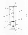
- FIG 3 shows the microfluidic cartridge 10 of Figure 1 seen from the side..
- the microfluidic cartridge 10 comprises a substrate 12 with five cavities in the form of channels 11.
- the channels 11 are provided in the form of grooves covered with a foil 11a.
- Each channel 11 is connected with an inlet 13 and at their opposite end the channels 11 are connected with a common sink 14.
- the inlet 13 has the shape of a well.
- the wall By pressing the flexible wall section 15 of the sink 14, the wall will be moved and air will be pressed out of the channels 11, and when the pressure is released the flexible wall section 15 will return to its initial position and a liquid sample arranged in the inlet 13 will be sucked into the channel 11 to a desired position.
- the liquid sample By further manipulating the flexible wall section the liquid sample can be drawn further into the channels 11 or it may be pulsated in the channels.
- the flexible wall section 15 may be manipulated to collect the sample in the sink and to re-flush the sample into the channels, if desired.
- the flexible wall section 15 thereby provides a simple and cheap method of controlling a liquid sample in the micro fluidic device.
- the micro fluidic cartridge also comprises an indent which provides a read out section 16 for the channels 11.
- the channels comprise a transparent window and the magnetic particles can be temporally immobilized using a not shown magnet.
- the magnet is mounted in the detector assembly which also includes a reading for reading signals through the read section 16.
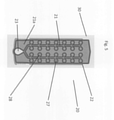
- FIGS 4 and 5 show alternative embodiments of the microfluidic cartridge 20.
- microfluidic cartridge 20 is seen with two channels 21, which in one end is connected with an inlet 23 and in the opposite end connected with sinks 24.
- each chamber is connected with the channel and each chamber may comprise an analyte, which may react with a liquid sample which will fill the chambers when it passes from the inlet 23, through the channels 21 to the sink 24.
- the channels 21, the inlet 23, the sinks 24, and the chambers 27, 28 are formed as recesses in the substrate 22.
- the access to the channels 21, the sinks 24, and the chambers 27, 28 are closed by a foil 21a, so they are only accessible via the inlet 23.
- the chambers 27 and 28 are placed in pairs on each side of the channel 21.
- the chambers may comprise the same or different analytes.
- each pair along the channel may comprise the same analyte so the sample will be tested twice with same analyte, thereby improving the certainty of the measured results.
- the microfluidic cartridge 20 shown in Figure 4 may e.g. be able to measure with twelve different analytes, i.e. the microfluidic cartridge 20 comprises twelve pairs of chambers 27, 28 located along the channels 21.
- the analytes may be a combination of analytes, which may be measured with different means, such as optical, electrical or magnetic means.
- the analytes may e.g. be immobilized magnetic particles or immobilized enzymes functioning as color-forming reactants, which will react with the liquid sample, when the sample enters the chamber.
- FIG. 5 shows a microfluidic cartridge 20 which substantially corresponds to the microfluidic cartridge shown in Figure 4 .
- the sinks are omitted in this particular embodiment.
- the microfluidic cartridge comprises an inlet 23 connected with two channels 21, which are connected with pairs of chambers 27, 28 along the channels.
- the chambers 27 and 28 are transparent to light from a light source e.g. a multicolor-LED. As such the chambers 27 and 28 are suitable for use with optical detection means.
- microfluidic cartridge illustrated in Figure 5 is used as an example of some measurements which may be performed with the microfluidic detection system.
- Figure 6 shows an optical detection system in which an LED 30 emits a substantial monochromatic light beam towards a chamber in the microfluidic cartridge 20.
- the light beam bases the sample in the chamber and is transformed to a light beam 32 with different wavelength.
- the light beam 32 is detected by the CCD detector 35 below the microfluidic cartridge 20.
- Figure 7 shows another example in which the microfluidic cartridge 20 receives a light beam 31 emitted from the LED 30.
- the light beam 31 is reflected by the sample in the chamber of the microfluidic cartridge.
- the reflected light is divided into light with two different wavelengths 32 and 33 which are detected by the CCD detector 35 placed on the same side of the microfluidic cartridge 20 as the LED 30.
- Figure 8 shows yet another exampleof the detection system.
- the detection system utilizes a spectrometer 36 for detection of the light reflected from the sample in a chamber of the microfluidic cartridge 20.
- the light beam 31 is emitted from the LED 30 and reflected by the sample held in the microfluidic cartridge 20.
- the reflected light is reflected as light with three different wavelengths 32, 33 and 34.
- the reflected light is detected by the spectrometer 36 and the resulting curve is shown in the inserted box 37.
- Figure 9 illustrates an embodiment of the detection system. This is a system where an array or electrodes 38 send a current through one or more of the chambers in the microfluidic cartridge 20. Due to the resistance in the sample, the detection system will be able to detect the nature of the sample.
- FIG 10 illustrates the principles of a light tunnel.
- the light tunnel includes three LEDs 30a, 30b and 30 c, each emitting light with a wavelength which is different from the wavelengths of the other two LEDs.
- the LED 30a may emit light in the range: 610 ⁇ 760.
- the LED 30b may emit light in the range 570 ⁇ 590, and finally the LED 30c may emit light in the range: 450 ⁇ 500.
- Each LED is intended to emit light to one or more specific detection sites, and to avoid transmission of incident light to detection sites where it is not desired, the light tunnel is constructed with partition members 39 which will ensure that undesired transmission of incident light is avoided.
- each LED 30a, 30b and 30c is enclosed by partitions members 39, which will ensure that the light emitted from the LED only transmits light to the detection site for which the light is intended.
- the light tunnel makes it possible to transmit light through two or more detection sites simultaneously.
- the LEDs 30a, 30b and 30c transmit light simultaneously through three different detection sites on the microfluidic cartridge 20.
- the resulting light beams are detected by the CCD detector 35.
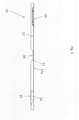
- FIG 11 shows an embodiment of a microfluidic cartridge 40 according to the invention.
- the the microfluidic cartridge 40 comprises an inlet 43 for introduction of a sample.
- the inlet 43 is connected with a channel 41 which in the opposite end is connected with a sink 44.
- a channel 41 which in the opposite end is connected with a sink 44.
- the channel 41 Along the length of the channel 41 are located two detection sites 47 for optical detection and further two detection sites 48 for electrical detection.
- the electrical detection sites 48 may comprise electrodes which are connected with connection pads 50 by means of electrical wiring 49.
- the electrical wiring may be printed on the substrate 42 of the the microfluidic cartridge 40.
- connection pads 50 may be connected with corresponding connection pads in the detection assembly and to an electrical reader, such as a voltmeter.
Landscapes
- Chemical & Material Sciences (AREA)
- Physics & Mathematics (AREA)
- Health & Medical Sciences (AREA)
- Analytical Chemistry (AREA)
- Immunology (AREA)
- Life Sciences & Earth Sciences (AREA)
- General Health & Medical Sciences (AREA)
- Biochemistry (AREA)
- General Physics & Mathematics (AREA)
- Pathology (AREA)
- Spectroscopy & Molecular Physics (AREA)
- Chemical Kinetics & Catalysis (AREA)
- Clinical Laboratory Science (AREA)
- Dispersion Chemistry (AREA)
- Optics & Photonics (AREA)
- Nuclear Medicine, Radiotherapy & Molecular Imaging (AREA)
- Molecular Biology (AREA)
- Electrochemistry (AREA)
- Hematology (AREA)
- Investigating, Analyzing Materials By Fluorescence Or Luminescence (AREA)
- Investigating Or Analysing Materials By Optical Means (AREA)
- Automatic Analysis And Handling Materials Therefor (AREA)
- Optical Measuring Cells (AREA)
- Investigating Or Analysing Materials By The Use Of Chemical Reactions (AREA)
- Investigating Or Analysing Biological Materials (AREA)
- Sampling And Sample Adjustment (AREA)
Claims (8)
- Cartouche microfluidique permettant d'effectuer une pluralité de dosages différents, la cartouche (40) comprenant au moins un canal d'écoulement (41) et une entrée (43) vers le canal d'écoulement permettant d'alimenter un échantillon liquide vers le canal d'écoulement (41), le canal d'écoulement (41) comprenant une pluralité de sites de détection (47, 48) comprenant au moins un site de détection électrique (48) comprenant des électrodes conçues pour effectuer une détection électrochimique au niveau du site de détection électrique (48), et au moins un site de détection optique (47) doté d'une fenêtre transparente pour une lecture optique au niveau du site de détection optique (47), ladite cartouche microfluidique (40) comprenant un substrat solide doté en son sein d'une cavité en forme de canal et une feuille polymère collée audit substrat solide pour recouvrir la cavité en forme de canal de manière à définir ledit au moins un canal d'écoulement (41) entre la feuille polymère et le substrat et de manière à définir l'entrée, ledit au moins un site de détection électrique (48) et ledit au moins une site de détection optique (47) se trouvant dans ledit au moins un canal d'écoulement (41) et ladite feuille étant un polymère portant les électrodes pour ledit au moins un site de détection électrique (48) et portant des lignes de transmission électrique (49) pour la lecture à partir des électrodes.
- Cartouche microfluidique selon la revendication 1, au moins l'une des électrodes ou au moins l'une des lignes de transmission électrique (49) étant imprimée.
- Cartouche microfluidique selon la revendication 1 ou la revendication 2, lesdites électrodes se trouvant des deux côtés de la feuille.
- Cartouche microfluidique selon la revendication 1 ou la revendication 2, au moins une partie des lignes de transmission électrique (49) est noyée dans la feuille polymère.
- Cartouche microfluidique selon l'une quelconque des revendications 1 à 4, ladite cartouche comprenant des plots de connexion (50) conçus pour être connectés aux plots de connexion d'un voltmètre, les électrodes étant connectées aux plots de connexion par l'intermédiaire des lignes de transmission électrique (49) et les électrodes étant implantées pour transmettre un courant à travers un échantillon liquide se trouvant au niveau du site de détection électrique (48).
- Système de détection microfluidique comprenant une cartouche microfluidique selon l'une quelconque des revendications précédentes et un ensemble détecteur,
l'ensemble détecteur comprenant une fente pour insérer la cartouche microfluidique et au moins un lecteur électrique pour lire des signaux électriques sortant du ou des sites de détection électrique (48) par l'intermédiaire desdits plots de connexion (50) lorsque ladite cartouche (40) est insérée dans une première ou une seconde position prédéfinie dans ladite fente, lesdites positions prédéfinies de ladite cartouche microfluidique (40) étant déterminées par des brides saillantes agencées sur la cartouche microfluidique et des cavités agencées sur l'ensemble détecteur dans des positions sélectionnées ou des brides saillantes agencées sur l'ensemble détecteur et des cavités agencées sur la cartouche microfluidique dans les positions sélectionnées, qui s'engagent ou s'encliquettent en place pour positionner temporairement la cartouche microfluidique (40) dans l'ensemble détecteur dans l'une des première et seconde positions prédéfinies, lesdites brides saillantes et cavités comprenant un premier ensemble de brides saillantes et de cavités qui correspondent à la première position prédéfinie et lesdites brides saillantes et cavités comprenant un second ensemble de brides saillantes et de cavités qui correspondent à la seconde position prédéfinie. - Système de détection microfluidique selon la revendication 6, ledit lecteur électrique comprenant un voltmètre connecté électriquement à des plots de connexion de voltmètre se trouvant dans la fente, lesdits plots de connexion (50) de la cartouche (40) étant en connexion électrique avec les plots de connexion de voltmètre lorsqu'ils sont insérés dans la fente dans l'une des première et seconde positions prédéfinies.
- Système de détection microfluidique selon la revendication 7, lesdites électrodes étant connectées aux plots de connexion de la cartouche (50) par l'intermédiaire des lignes de transmission électrique (49) et lesdites électrodes étant implantées pour transmettre un courant à travers un échantillon liquide se trouvant sur le site de détection électrique (48) lorsque lesdits plots de connexion de la cartouche sont en connexion électrique avec les plots de connexion du voltmètre lorsqu'ils sont insérés dans la fente dans l'une des première et seconde positions prédéfinies.
Applications Claiming Priority (3)
| Application Number | Priority Date | Filing Date | Title |
|---|---|---|---|
| DKPA201470363 | 2014-06-18 | ||
| PCT/DK2015/050166 WO2015192855A1 (fr) | 2014-06-18 | 2015-06-15 | Système de détection micro-fluidique, et cartouche micro-fluidique |
| EP15810324.2A EP3158317B8 (fr) | 2014-06-18 | 2015-06-15 | Système de détection micro-fluidique |
Related Parent Applications (2)
| Application Number | Title | Priority Date | Filing Date |
|---|---|---|---|
| EP15810324.2A Division EP3158317B8 (fr) | 2014-06-18 | 2015-06-15 | Système de détection micro-fluidique |
| EP15810324.2A Division-Into EP3158317B8 (fr) | 2014-06-18 | 2015-06-15 | Système de détection micro-fluidique |
Publications (2)
| Publication Number | Publication Date |
|---|---|
| EP3623794A1 EP3623794A1 (fr) | 2020-03-18 |
| EP3623794B1 true EP3623794B1 (fr) | 2022-03-02 |
Family
ID=54934895
Family Applications (2)
| Application Number | Title | Priority Date | Filing Date |
|---|---|---|---|
| EP19198299.0A Active EP3623794B1 (fr) | 2014-06-18 | 2015-06-15 | Système de détection microfluidique et une cartouche microfluidique |
| EP15810324.2A Active EP3158317B8 (fr) | 2014-06-18 | 2015-06-15 | Système de détection micro-fluidique |
Family Applications After (1)
| Application Number | Title | Priority Date | Filing Date |
|---|---|---|---|
| EP15810324.2A Active EP3158317B8 (fr) | 2014-06-18 | 2015-06-15 | Système de détection micro-fluidique |
Country Status (12)
| Country | Link |
|---|---|
| US (2) | US10307754B2 (fr) |
| EP (2) | EP3623794B1 (fr) |
| JP (2) | JP6603675B2 (fr) |
| KR (2) | KR102466599B1 (fr) |
| CN (2) | CN106662522B (fr) |
| AU (2) | AU2015276638B2 (fr) |
| BR (1) | BR112016029490B1 (fr) |
| CA (2) | CA2951959A1 (fr) |
| ES (2) | ES2760073T3 (fr) |
| MX (2) | MX2016016828A (fr) |
| PT (2) | PT3623794T (fr) |
| WO (1) | WO2015192855A1 (fr) |
Families Citing this family (14)
| Publication number | Priority date | Publication date | Assignee | Title |
|---|---|---|---|---|
| EP2906928A4 (fr) | 2012-10-15 | 2016-11-09 | Nanocellect Biomedical Inc | Systèmes, appareil et procédés de tri de particules |
| TWI789343B (zh) * | 2016-02-01 | 2023-01-11 | 丹麥商碩騰丹麥有限公司 | 微流體分析系統、執行分析的微流體匣及方法 |
| EP3315963A1 (fr) * | 2016-10-26 | 2018-05-02 | Fuchs Petrolub SE | Élément de réception d'échantillons, kit d'analyse et procédé d'analyse d'un liquide, en particulier d'une émulsion d'huile de refroidissement |
| CN107462735B (zh) * | 2017-08-10 | 2020-06-02 | 天津派普大业仪器科技有限公司 | 基于微流控技术的两次加样检测方法 |
| CN107643394B (zh) * | 2017-08-29 | 2020-06-02 | 天津派普大业仪器科技有限公司 | 微流控放射免疫两步检测法 |
| BR112021003395A2 (pt) * | 2018-08-23 | 2021-05-18 | Sanwa Biotech Ltd | aparelho de diagnóstico portátil e método do mesmo |
| US10738342B2 (en) * | 2018-08-30 | 2020-08-11 | Urinary Technologies, Inc. | System for microbial species detection, quantification and antibiotic susceptibility identification |
| CN213148721U (zh) * | 2019-11-22 | 2021-05-07 | 京东方科技集团股份有限公司 | 分析仪及检测系统 |
| US20220244231A1 (en) * | 2019-11-22 | 2022-08-04 | Boe Technology Group Co., Ltd. | Dairy Solution Analysis Method and Portable Dairy Solution Analysis Device |
| CN113720817B (zh) * | 2021-08-27 | 2024-04-09 | 苏州国科均豪生物科技有限公司 | 一种盘式微流控检测分析系统 |
| CN114210377B (zh) * | 2021-12-21 | 2023-01-06 | 哈尔滨工业大学 | 一种基于电场调控的便携式多功能可视化微流体设备 |
| CN114995548A (zh) * | 2022-06-28 | 2022-09-02 | 中国人民解放军空军军医大学 | 一种兼具升降温功能的宽程多阶温度控制装置 |
| CN116399910B (zh) * | 2023-06-05 | 2023-09-01 | 湖北工业大学 | 一种用于gis设备的微流控气体检测装置 |
| CN116990288B (zh) * | 2023-07-24 | 2024-02-06 | 扬州大学 | 一种基于微流控的镉离子逻辑检测装置 |
Family Cites Families (54)
| Publication number | Priority date | Publication date | Assignee | Title |
|---|---|---|---|---|
| US3910701A (en) | 1973-07-30 | 1975-10-07 | George R Henderson | Method and apparatus for measuring light reflectance absorption and or transmission |
| US5304487A (en) | 1992-05-01 | 1994-04-19 | Trustees Of The University Of Pennsylvania | Fluid handling in mesoscale analytical devices |
| CA2134477C (fr) | 1992-05-01 | 1999-07-06 | Peter Wilding | Analyse fondee sur la restriction de l'ecoulement |
| US6207369B1 (en) | 1995-03-10 | 2001-03-27 | Meso Scale Technologies, Llc | Multi-array, multi-specific electrochemiluminescence testing |
| US5609828A (en) * | 1995-05-31 | 1997-03-11 | bio M erieux Vitek, Inc. | Sample card |
| ATE400358T1 (de) * | 1997-12-24 | 2008-07-15 | Cepheid | Vorrichtung und verfahren zur lyse |
| AU3771599A (en) * | 1998-05-18 | 1999-12-06 | University Of Washington | Liquid analysis cartridge |
| US20020177135A1 (en) * | 1999-07-27 | 2002-11-28 | Doung Hau H. | Devices and methods for biochip multiplexing |
| US7277166B2 (en) * | 2000-08-02 | 2007-10-02 | Honeywell International Inc. | Cytometer analysis cartridge optical configuration |
| US6870165B2 (en) | 2001-10-19 | 2005-03-22 | Biocal Technology, Inc. | Multi-color multiplexed analysis in a bio-separation system |
| JP4203938B2 (ja) | 2001-11-26 | 2009-01-07 | 東拓工業株式会社 | 分岐継手及びこれを用いた管の接続構造 |
| US7569393B2 (en) * | 2002-06-28 | 2009-08-04 | International Technidyne Corporation | Analytical test cartridge; and, methods |
| US7011794B2 (en) * | 2002-11-25 | 2006-03-14 | Immunivest Corporation | Upon a cartridge for containing a specimen sample for optical analysis |
| EP2711415B1 (fr) * | 2002-12-26 | 2022-02-16 | Meso Scale Technologies, LLC. | Cartouches de test et procédés d'utilisation |
| DE602004028463D1 (de) * | 2003-05-30 | 2010-09-16 | Pelikan Technologies Inc | Verfahren und vorrichtung zur injektion von flüssigkeit |
| JPWO2005024437A1 (ja) | 2003-09-05 | 2007-11-08 | 日本電気株式会社 | 測定システム |
| US7723099B2 (en) * | 2003-09-10 | 2010-05-25 | Abbott Point Of Care Inc. | Immunoassay device with immuno-reference electrode |
| US7887750B2 (en) | 2004-05-05 | 2011-02-15 | Bayer Healthcare Llc | Analytical systems, devices, and cartridges therefor |
| US7695676B2 (en) | 2004-08-11 | 2010-04-13 | Hans Kloepfer | Methods and apparatus for analyzing an analysis fluid |
| US7524672B2 (en) | 2004-09-22 | 2009-04-28 | Sandia Corporation | Microfluidic microarray systems and methods thereof |
| EP1827693B1 (fr) | 2004-12-09 | 2010-03-24 | Scandinavian Micro Biodevices ApS | Dispositif microfluidique et procedes permettant de produire ce dispositif microfluidique |
| CN101031802B (zh) * | 2005-01-07 | 2012-11-07 | 积水化学工业株式会社 | 使用盒的检测装置 |
| GB0502556D0 (en) * | 2005-02-08 | 2005-03-16 | Lab901 Ltd | Analysis instrument |
| IES20050304A2 (en) | 2005-05-11 | 2006-11-15 | Haemoglobal Biotech Ltd | A mobile chemistry and haematology analyser with an intergrated diagnostic databank |
| US20100261286A1 (en) * | 2005-07-14 | 2010-10-14 | Young Hoon Kim | Microfluidic devices and methods of preparing and using the same |
| US7791728B2 (en) | 2005-08-11 | 2010-09-07 | Hewlett-Packard Development Company, L.P. | System for optically analyzing a substance with a selected single-wavelength |
| JP5155661B2 (ja) | 2005-09-06 | 2013-03-06 | アークレイ株式会社 | 微細流路用流量計およびこれを用いた分析装置、分析装置用カートリッジ |
| JP2009521684A (ja) * | 2005-12-22 | 2009-06-04 | ハネウェル・インターナショナル・インコーポレーテッド | 携帯用サンプル分析装置のカートリッジ |
| US7498177B2 (en) | 2006-04-24 | 2009-03-03 | Jesus Martinez De La Fuente | Quantum dots and their uses |
| CN1869662A (zh) * | 2006-05-15 | 2006-11-29 | 清华大学 | 一种多通道柱成像荧光检测器 |
| EP2101917A1 (fr) | 2007-01-10 | 2009-09-23 | Scandinavian Micro Biodevices A/S | Dispositif et systèmes microfluidiques et méthode d'exécution d'un essai |
| CN201002227Y (zh) | 2007-02-02 | 2008-01-09 | 张聪因 | 棘轮板手的制动结构 |
| JP5119872B2 (ja) | 2007-11-12 | 2013-01-16 | トヨタ紡織株式会社 | 車両用換気装置 |
| US9201059B2 (en) | 2008-03-14 | 2015-12-01 | Scandinavian Micro Biodevices Aps | Microfluidic system and a method of performing a test |
| CN104155210B (zh) | 2008-10-02 | 2017-08-22 | 彼克斯赛尔医疗科技有限公司 | 基于粘弹性聚焦的光学成像 |
| JP2012511156A (ja) | 2008-12-05 | 2012-05-17 | ナノアイヴイディー,インコーポレイテッド | ポイント・オブ・ケア分析器用マイクロ流体ベースのラボオンテストカード |
| KR101179550B1 (ko) * | 2008-12-22 | 2012-09-05 | 한국전자통신연구원 | 액체 시료 분석용 칩 판독 시스템, 이를 이용한 분석 방법 및 유비쿼터스 판독 시스템 |
| WO2010088514A1 (fr) | 2009-01-30 | 2010-08-05 | Micronics, Inc. | Système portable de détection de fluorescence à gain élevé |
| DE102009016712A1 (de) | 2009-04-09 | 2010-10-14 | Bayer Technology Services Gmbh | Einweg-Mikrofluidik-Testkassette zur Bioassay von Analyten |
| AU2011239538B2 (en) | 2010-04-16 | 2014-10-23 | Opko Diagnostics, Llc | Systems and devices for analysis of samples |
| WO2012016107A1 (fr) | 2010-07-30 | 2012-02-02 | Sdix | Procédés et kits de détection de salmonelle enteritidis et sérotypes associés |
| GB201014805D0 (en) * | 2010-09-07 | 2010-10-20 | Multi Sense Technologies Ltd | Microfluidics based assay device |
| TW201217783A (en) * | 2010-09-15 | 2012-05-01 | Mbio Diagnostics Inc | System and method for detecting multiple molecules in one assay |
| CN103329081A (zh) * | 2010-12-09 | 2013-09-25 | 阿尔·祺福 | 用于流体样本分析的微流控装置 |
| CA2853615C (fr) * | 2011-04-20 | 2016-07-05 | Mesa Tech International, Inc. | Dispositif integre pour la detection et l'identification d'acide nucleique |
| US8717556B2 (en) * | 2011-07-27 | 2014-05-06 | Aptina Imaging Corporation | Microfluidic systems with chemical pumps |
| US8804105B2 (en) * | 2012-03-27 | 2014-08-12 | E. I. Spectra, Llc | Combined optical imaging and electrical detection to characterize particles carried in a fluid |
| CN102628805B (zh) * | 2012-04-26 | 2014-10-15 | 大连理工大学 | 基于光子晶体滤波片的微流控芯片荧光检测系统 |
| CN103381376B (zh) * | 2012-05-02 | 2014-12-10 | 李木 | 一种无人值守型数字式微流控系统及其控制方法 |
| CN104525284A (zh) * | 2012-05-02 | 2015-04-22 | 李木 | 一种分立式数字微流控系统及其控制方法 |
| US8735853B2 (en) * | 2012-06-09 | 2014-05-27 | E.I. Spectra, Llc | Fluorescence flow cytometry |
| DK2864781T3 (en) | 2012-06-22 | 2018-02-05 | Scandinavian Micro Biodevices Aps | A METHOD AND SYSTEM FOR QUANTITATIVE OR QUALITATIVE DETERMINATION OF A TARGET COMPONENT |
| CN102829681B (zh) | 2012-07-27 | 2016-05-04 | 胡兆贤 | 一种制动卷尺 |
| JP2014071056A (ja) * | 2012-10-01 | 2014-04-21 | Sony Corp | 光学的測定装置及び光学的測定用マイクロチップ |
-
2015
- 2015-06-15 AU AU2015276638A patent/AU2015276638B2/en active Active
- 2015-06-15 CA CA2951959A patent/CA2951959A1/fr active Pending
- 2015-06-15 PT PT191982990T patent/PT3623794T/pt unknown
- 2015-06-15 EP EP19198299.0A patent/EP3623794B1/fr active Active
- 2015-06-15 EP EP15810324.2A patent/EP3158317B8/fr active Active
- 2015-06-15 ES ES15810324T patent/ES2760073T3/es active Active
- 2015-06-15 WO PCT/DK2015/050166 patent/WO2015192855A1/fr active Application Filing
- 2015-06-15 KR KR1020217038876A patent/KR102466599B1/ko active IP Right Grant
- 2015-06-15 MX MX2016016828A patent/MX2016016828A/es active IP Right Grant
- 2015-06-15 ES ES19198299T patent/ES2910383T3/es active Active
- 2015-06-15 BR BR112016029490-4A patent/BR112016029490B1/pt active IP Right Grant
- 2015-06-15 CA CA3167526A patent/CA3167526A1/fr active Pending
- 2015-06-15 US US15/319,542 patent/US10307754B2/en active Active
- 2015-06-15 KR KR1020177001409A patent/KR102407905B1/ko active IP Right Grant
- 2015-06-15 CN CN201580038124.1A patent/CN106662522B/zh active Active
- 2015-06-15 JP JP2016573097A patent/JP6603675B2/ja active Active
- 2015-06-15 CN CN202010750347.3A patent/CN111871476B/zh active Active
- 2015-06-15 PT PT158103242T patent/PT3158317T/pt unknown
-
2016
- 2016-12-16 MX MX2020001500A patent/MX2020001500A/es unknown
-
2019
- 2019-03-13 US US16/351,953 patent/US11779919B2/en active Active
- 2019-08-12 AU AU2019216581A patent/AU2019216581B2/en active Active
- 2019-10-11 JP JP2019187299A patent/JP6890758B2/ja active Active
Non-Patent Citations (1)
| Title |
|---|
| None * |
Also Published As
Similar Documents
| Publication | Publication Date | Title |
|---|---|---|
| EP3623794B1 (fr) | Système de détection microfluidique et une cartouche microfluidique | |
| JP5203453B2 (ja) | 集積光学および流体制御要素を有する反応容器 | |
| US20120003659A1 (en) | Strobo thin film chemical analysis apparatus and assay method using the same | |
| US20210293740A1 (en) | Devices, systems, and methods for performing optical and electrochemical assays | |
| US20210310978A1 (en) | Techniques for performing optical and electrochemical assays with universal circuitry | |
| US20220113246A1 (en) | Devices, systems, and methods for performing optical assays |
Legal Events
| Date | Code | Title | Description |
|---|---|---|---|
| PUAI | Public reference made under article 153(3) epc to a published international application that has entered the european phase |
Free format text: ORIGINAL CODE: 0009012 |
|
| STAA | Information on the status of an ep patent application or granted ep patent |
Free format text: STATUS: THE APPLICATION HAS BEEN PUBLISHED |
|
| AC | Divisional application: reference to earlier application |
Ref document number: 3158317 Country of ref document: EP Kind code of ref document: P |
|
| AK | Designated contracting states |
Kind code of ref document: A1 Designated state(s): AL AT BE BG CH CY CZ DE DK EE ES FI FR GB GR HR HU IE IS IT LI LT LU LV MC MK MT NL NO PL PT RO RS SE SI SK SM TR |
|
| STAA | Information on the status of an ep patent application or granted ep patent |
Free format text: STATUS: REQUEST FOR EXAMINATION WAS MADE |
|
| 17P | Request for examination filed |
Effective date: 20200618 |
|
| RBV | Designated contracting states (corrected) |
Designated state(s): AL AT BE BG CH CY CZ DE DK EE ES FI FR GB GR HR HU IE IS IT LI LT LU LV MC MK MT NL NO PL PT RO RS SE SI SK SM TR |
|
| STAA | Information on the status of an ep patent application or granted ep patent |
Free format text: STATUS: EXAMINATION IS IN PROGRESS |
|
| 17Q | First examination report despatched |
Effective date: 20201120 |
|
| STAA | Information on the status of an ep patent application or granted ep patent |
Free format text: STATUS: EXAMINATION IS IN PROGRESS |
|
| GRAP | Despatch of communication of intention to grant a patent |
Free format text: ORIGINAL CODE: EPIDOSNIGR1 |
|
| STAA | Information on the status of an ep patent application or granted ep patent |
Free format text: STATUS: GRANT OF PATENT IS INTENDED |
|
| INTG | Intention to grant announced |
Effective date: 20210913 |
|
| GRAS | Grant fee paid |
Free format text: ORIGINAL CODE: EPIDOSNIGR3 |
|
| GRAA | (expected) grant |
Free format text: ORIGINAL CODE: 0009210 |
|
| STAA | Information on the status of an ep patent application or granted ep patent |
Free format text: STATUS: THE PATENT HAS BEEN GRANTED |
|
| AC | Divisional application: reference to earlier application |
Ref document number: 3158317 Country of ref document: EP Kind code of ref document: P |
|
| AK | Designated contracting states |
Kind code of ref document: B1 Designated state(s): AL AT BE BG CH CY CZ DE DK EE ES FI FR GB GR HR HU IE IS IT LI LT LU LV MC MK MT NL NO PL PT RO RS SE SI SK SM TR |
|
| REG | Reference to a national code |
Ref country code: GB Ref legal event code: FG4D |
|
| REG | Reference to a national code |
Ref country code: CH Ref legal event code: EP Ref country code: AT Ref legal event code: REF Ref document number: 1472638 Country of ref document: AT Kind code of ref document: T Effective date: 20220315 |
|
| REG | Reference to a national code |
Ref country code: DE Ref legal event code: R096 Ref document number: 602015077345 Country of ref document: DE |
|
| REG | Reference to a national code |
Ref country code: IE Ref legal event code: FG4D |
|
| REG | Reference to a national code |
Ref country code: PT Ref legal event code: SC4A Ref document number: 3623794 Country of ref document: PT Date of ref document: 20220408 Kind code of ref document: T Free format text: AVAILABILITY OF NATIONAL TRANSLATION Effective date: 20220404 |
|
| REG | Reference to a national code |
Ref country code: NL Ref legal event code: FP |
|
| REG | Reference to a national code |
Ref country code: ES Ref legal event code: FG2A Ref document number: 2910383 Country of ref document: ES Kind code of ref document: T3 Effective date: 20220512 |
|
| REG | Reference to a national code |
Ref country code: LT Ref legal event code: MG9D |
|
| PG25 | Lapsed in a contracting state [announced via postgrant information from national office to epo] |
Ref country code: SE Free format text: LAPSE BECAUSE OF FAILURE TO SUBMIT A TRANSLATION OF THE DESCRIPTION OR TO PAY THE FEE WITHIN THE PRESCRIBED TIME-LIMIT Effective date: 20220302 Ref country code: RS Free format text: LAPSE BECAUSE OF FAILURE TO SUBMIT A TRANSLATION OF THE DESCRIPTION OR TO PAY THE FEE WITHIN THE PRESCRIBED TIME-LIMIT Effective date: 20220302 Ref country code: NO Free format text: LAPSE BECAUSE OF FAILURE TO SUBMIT A TRANSLATION OF THE DESCRIPTION OR TO PAY THE FEE WITHIN THE PRESCRIBED TIME-LIMIT Effective date: 20220602 Ref country code: LT Free format text: LAPSE BECAUSE OF FAILURE TO SUBMIT A TRANSLATION OF THE DESCRIPTION OR TO PAY THE FEE WITHIN THE PRESCRIBED TIME-LIMIT Effective date: 20220302 Ref country code: HR Free format text: LAPSE BECAUSE OF FAILURE TO SUBMIT A TRANSLATION OF THE DESCRIPTION OR TO PAY THE FEE WITHIN THE PRESCRIBED TIME-LIMIT Effective date: 20220302 Ref country code: BG Free format text: LAPSE BECAUSE OF FAILURE TO SUBMIT A TRANSLATION OF THE DESCRIPTION OR TO PAY THE FEE WITHIN THE PRESCRIBED TIME-LIMIT Effective date: 20220602 |
|
| PG25 | Lapsed in a contracting state [announced via postgrant information from national office to epo] |
Ref country code: PL Free format text: LAPSE BECAUSE OF FAILURE TO SUBMIT A TRANSLATION OF THE DESCRIPTION OR TO PAY THE FEE WITHIN THE PRESCRIBED TIME-LIMIT Effective date: 20220302 Ref country code: LV Free format text: LAPSE BECAUSE OF FAILURE TO SUBMIT A TRANSLATION OF THE DESCRIPTION OR TO PAY THE FEE WITHIN THE PRESCRIBED TIME-LIMIT Effective date: 20220302 Ref country code: GR Free format text: LAPSE BECAUSE OF FAILURE TO SUBMIT A TRANSLATION OF THE DESCRIPTION OR TO PAY THE FEE WITHIN THE PRESCRIBED TIME-LIMIT Effective date: 20220603 Ref country code: FI Free format text: LAPSE BECAUSE OF FAILURE TO SUBMIT A TRANSLATION OF THE DESCRIPTION OR TO PAY THE FEE WITHIN THE PRESCRIBED TIME-LIMIT Effective date: 20220302 |
|
| PG25 | Lapsed in a contracting state [announced via postgrant information from national office to epo] |
Ref country code: SM Free format text: LAPSE BECAUSE OF FAILURE TO SUBMIT A TRANSLATION OF THE DESCRIPTION OR TO PAY THE FEE WITHIN THE PRESCRIBED TIME-LIMIT Effective date: 20220302 Ref country code: SK Free format text: LAPSE BECAUSE OF FAILURE TO SUBMIT A TRANSLATION OF THE DESCRIPTION OR TO PAY THE FEE WITHIN THE PRESCRIBED TIME-LIMIT Effective date: 20220302 Ref country code: RO Free format text: LAPSE BECAUSE OF FAILURE TO SUBMIT A TRANSLATION OF THE DESCRIPTION OR TO PAY THE FEE WITHIN THE PRESCRIBED TIME-LIMIT Effective date: 20220302 Ref country code: EE Free format text: LAPSE BECAUSE OF FAILURE TO SUBMIT A TRANSLATION OF THE DESCRIPTION OR TO PAY THE FEE WITHIN THE PRESCRIBED TIME-LIMIT Effective date: 20220302 Ref country code: CZ Free format text: LAPSE BECAUSE OF FAILURE TO SUBMIT A TRANSLATION OF THE DESCRIPTION OR TO PAY THE FEE WITHIN THE PRESCRIBED TIME-LIMIT Effective date: 20220302 |
|
| PG25 | Lapsed in a contracting state [announced via postgrant information from national office to epo] |
Ref country code: IS Free format text: LAPSE BECAUSE OF FAILURE TO SUBMIT A TRANSLATION OF THE DESCRIPTION OR TO PAY THE FEE WITHIN THE PRESCRIBED TIME-LIMIT Effective date: 20220702 Ref country code: AL Free format text: LAPSE BECAUSE OF FAILURE TO SUBMIT A TRANSLATION OF THE DESCRIPTION OR TO PAY THE FEE WITHIN THE PRESCRIBED TIME-LIMIT Effective date: 20220302 |
|
| REG | Reference to a national code |
Ref country code: DE Ref legal event code: R097 Ref document number: 602015077345 Country of ref document: DE |
|
| PLBE | No opposition filed within time limit |
Free format text: ORIGINAL CODE: 0009261 |
|
| STAA | Information on the status of an ep patent application or granted ep patent |
Free format text: STATUS: NO OPPOSITION FILED WITHIN TIME LIMIT |
|
| PG25 | Lapsed in a contracting state [announced via postgrant information from national office to epo] |
Ref country code: MC Free format text: LAPSE BECAUSE OF FAILURE TO SUBMIT A TRANSLATION OF THE DESCRIPTION OR TO PAY THE FEE WITHIN THE PRESCRIBED TIME-LIMIT Effective date: 20220302 Ref country code: DK Free format text: LAPSE BECAUSE OF FAILURE TO SUBMIT A TRANSLATION OF THE DESCRIPTION OR TO PAY THE FEE WITHIN THE PRESCRIBED TIME-LIMIT Effective date: 20220302 |
|
| 26N | No opposition filed |
Effective date: 20221205 |
|
| PG25 | Lapsed in a contracting state [announced via postgrant information from national office to epo] |
Ref country code: SI Free format text: LAPSE BECAUSE OF FAILURE TO SUBMIT A TRANSLATION OF THE DESCRIPTION OR TO PAY THE FEE WITHIN THE PRESCRIBED TIME-LIMIT Effective date: 20220302 |
|
| REG | Reference to a national code |
Ref country code: AT Ref legal event code: UEP Ref document number: 1472638 Country of ref document: AT Kind code of ref document: T Effective date: 20220302 |
|
| PGFP | Annual fee paid to national office [announced via postgrant information from national office to epo] |
Ref country code: LU Payment date: 20230512 Year of fee payment: 9 |
|
| PGFP | Annual fee paid to national office [announced via postgrant information from national office to epo] |
Ref country code: IE Payment date: 20230526 Year of fee payment: 9 Ref country code: FR Payment date: 20230509 Year of fee payment: 9 Ref country code: DE Payment date: 20230509 Year of fee payment: 9 Ref country code: PT Payment date: 20230526 Year of fee payment: 9 Ref country code: NL Payment date: 20230511 Year of fee payment: 9 Ref country code: IT Payment date: 20230613 Year of fee payment: 9 |
|
| PGFP | Annual fee paid to national office [announced via postgrant information from national office to epo] |
Ref country code: AT Payment date: 20230526 Year of fee payment: 9 |
|
| PGFP | Annual fee paid to national office [announced via postgrant information from national office to epo] |
Ref country code: BE Payment date: 20230510 Year of fee payment: 9 |
|
| PGFP | Annual fee paid to national office [announced via postgrant information from national office to epo] |
Ref country code: GB Payment date: 20230510 Year of fee payment: 9 Ref country code: ES Payment date: 20230703 Year of fee payment: 9 Ref country code: CH Payment date: 20230701 Year of fee payment: 9 |
|
| PG25 | Lapsed in a contracting state [announced via postgrant information from national office to epo] |
Ref country code: MK Free format text: LAPSE BECAUSE OF FAILURE TO SUBMIT A TRANSLATION OF THE DESCRIPTION OR TO PAY THE FEE WITHIN THE PRESCRIBED TIME-LIMIT Effective date: 20220302 Ref country code: CY Free format text: LAPSE BECAUSE OF FAILURE TO SUBMIT A TRANSLATION OF THE DESCRIPTION OR TO PAY THE FEE WITHIN THE PRESCRIBED TIME-LIMIT Effective date: 20220302 |