EP3623794B1 - A microfluidic detection system and a microfluidic cartridge - Google Patents
A microfluidic detection system and a microfluidic cartridge Download PDFInfo
- Publication number
- EP3623794B1 EP3623794B1 EP19198299.0A EP19198299A EP3623794B1 EP 3623794 B1 EP3623794 B1 EP 3623794B1 EP 19198299 A EP19198299 A EP 19198299A EP 3623794 B1 EP3623794 B1 EP 3623794B1
- Authority
- EP
- European Patent Office
- Prior art keywords
- electrical
- microfluidic
- cartridge
- microfluidic cartridge
- electrodes
- Prior art date
- Legal status (The legal status is an assumption and is not a legal conclusion. Google has not performed a legal analysis and makes no representation as to the accuracy of the status listed.)
- Active
Links
Images


Classifications
-
- B—PERFORMING OPERATIONS; TRANSPORTING
- B01—PHYSICAL OR CHEMICAL PROCESSES OR APPARATUS IN GENERAL
- B01L—CHEMICAL OR PHYSICAL LABORATORY APPARATUS FOR GENERAL USE
- B01L3/00—Containers or dishes for laboratory use, e.g. laboratory glassware; Droppers
- B01L3/50—Containers for the purpose of retaining a material to be analysed, e.g. test tubes
- B01L3/502—Containers for the purpose of retaining a material to be analysed, e.g. test tubes with fluid transport, e.g. in multi-compartment structures
- B01L3/5027—Containers for the purpose of retaining a material to be analysed, e.g. test tubes with fluid transport, e.g. in multi-compartment structures by integrated microfluidic structures, i.e. dimensions of channels and chambers are such that surface tension forces are important, e.g. lab-on-a-chip
- B01L3/502715—Containers for the purpose of retaining a material to be analysed, e.g. test tubes with fluid transport, e.g. in multi-compartment structures by integrated microfluidic structures, i.e. dimensions of channels and chambers are such that surface tension forces are important, e.g. lab-on-a-chip characterised by interfacing components, e.g. fluidic, electrical, optical or mechanical interfaces
-
- G—PHYSICS
- G01—MEASURING; TESTING
- G01N—INVESTIGATING OR ANALYSING MATERIALS BY DETERMINING THEIR CHEMICAL OR PHYSICAL PROPERTIES
- G01N21/00—Investigating or analysing materials by the use of optical means, i.e. using sub-millimetre waves, infrared, visible or ultraviolet light
- G01N21/62—Systems in which the material investigated is excited whereby it emits light or causes a change in wavelength of the incident light
- G01N21/63—Systems in which the material investigated is excited whereby it emits light or causes a change in wavelength of the incident light optically excited
- G01N21/64—Fluorescence; Phosphorescence
- G01N21/6428—Measuring fluorescence of fluorescent products of reactions or of fluorochrome labelled reactive substances, e.g. measuring quenching effects, using measuring "optrodes"
-
- B—PERFORMING OPERATIONS; TRANSPORTING
- B01—PHYSICAL OR CHEMICAL PROCESSES OR APPARATUS IN GENERAL
- B01L—CHEMICAL OR PHYSICAL LABORATORY APPARATUS FOR GENERAL USE
- B01L9/00—Supporting devices; Holding devices
- B01L9/52—Supports specially adapted for flat sample carriers, e.g. for plates, slides, chips
- B01L9/527—Supports specially adapted for flat sample carriers, e.g. for plates, slides, chips for microfluidic devices, e.g. used for lab-on-a-chip
-
- G—PHYSICS
- G01—MEASURING; TESTING
- G01N—INVESTIGATING OR ANALYSING MATERIALS BY DETERMINING THEIR CHEMICAL OR PHYSICAL PROPERTIES
- G01N21/00—Investigating or analysing materials by the use of optical means, i.e. using sub-millimetre waves, infrared, visible or ultraviolet light
- G01N21/01—Arrangements or apparatus for facilitating the optical investigation
- G01N21/03—Cuvette constructions
- G01N21/05—Flow-through cuvettes
-
- G—PHYSICS
- G01—MEASURING; TESTING
- G01N—INVESTIGATING OR ANALYSING MATERIALS BY DETERMINING THEIR CHEMICAL OR PHYSICAL PROPERTIES
- G01N21/00—Investigating or analysing materials by the use of optical means, i.e. using sub-millimetre waves, infrared, visible or ultraviolet light
- G01N21/17—Systems in which incident light is modified in accordance with the properties of the material investigated
- G01N21/25—Colour; Spectral properties, i.e. comparison of effect of material on the light at two or more different wavelengths or wavelength bands
- G01N21/255—Details, e.g. use of specially adapted sources, lighting or optical systems
-
- G—PHYSICS
- G01—MEASURING; TESTING
- G01N—INVESTIGATING OR ANALYSING MATERIALS BY DETERMINING THEIR CHEMICAL OR PHYSICAL PROPERTIES
- G01N21/00—Investigating or analysing materials by the use of optical means, i.e. using sub-millimetre waves, infrared, visible or ultraviolet light
- G01N21/17—Systems in which incident light is modified in accordance with the properties of the material investigated
- G01N21/25—Colour; Spectral properties, i.e. comparison of effect of material on the light at two or more different wavelengths or wavelength bands
- G01N21/31—Investigating relative effect of material at wavelengths characteristic of specific elements or molecules, e.g. atomic absorption spectrometry
-
- G—PHYSICS
- G01—MEASURING; TESTING
- G01N—INVESTIGATING OR ANALYSING MATERIALS BY DETERMINING THEIR CHEMICAL OR PHYSICAL PROPERTIES
- G01N27/00—Investigating or analysing materials by the use of electric, electrochemical, or magnetic means
- G01N27/26—Investigating or analysing materials by the use of electric, electrochemical, or magnetic means by investigating electrochemical variables; by using electrolysis or electrophoresis
- G01N27/403—Cells and electrode assemblies
-
- G—PHYSICS
- G01—MEASURING; TESTING
- G01N—INVESTIGATING OR ANALYSING MATERIALS BY DETERMINING THEIR CHEMICAL OR PHYSICAL PROPERTIES
- G01N35/00—Automatic analysis not limited to methods or materials provided for in any single one of groups G01N1/00 - G01N33/00; Handling materials therefor
- G01N35/00029—Automatic analysis not limited to methods or materials provided for in any single one of groups G01N1/00 - G01N33/00; Handling materials therefor provided with flat sample substrates, e.g. slides
-
- G—PHYSICS
- G01—MEASURING; TESTING
- G01N—INVESTIGATING OR ANALYSING MATERIALS BY DETERMINING THEIR CHEMICAL OR PHYSICAL PROPERTIES
- G01N35/00—Automatic analysis not limited to methods or materials provided for in any single one of groups G01N1/00 - G01N33/00; Handling materials therefor
- G01N35/00584—Control arrangements for automatic analysers
- G01N35/00722—Communications; Identification
- G01N35/00732—Identification of carriers, materials or components in automatic analysers
-
- B—PERFORMING OPERATIONS; TRANSPORTING
- B01—PHYSICAL OR CHEMICAL PROCESSES OR APPARATUS IN GENERAL
- B01L—CHEMICAL OR PHYSICAL LABORATORY APPARATUS FOR GENERAL USE
- B01L2200/00—Solutions for specific problems relating to chemical or physical laboratory apparatus
- B01L2200/02—Adapting objects or devices to another
- B01L2200/025—Align devices or objects to ensure defined positions relative to each other
-
- B—PERFORMING OPERATIONS; TRANSPORTING
- B01—PHYSICAL OR CHEMICAL PROCESSES OR APPARATUS IN GENERAL
- B01L—CHEMICAL OR PHYSICAL LABORATORY APPARATUS FOR GENERAL USE
- B01L2300/00—Additional constructional details
- B01L2300/02—Identification, exchange or storage of information
-
- B—PERFORMING OPERATIONS; TRANSPORTING
- B01—PHYSICAL OR CHEMICAL PROCESSES OR APPARATUS IN GENERAL
- B01L—CHEMICAL OR PHYSICAL LABORATORY APPARATUS FOR GENERAL USE
- B01L2300/00—Additional constructional details
- B01L2300/06—Auxiliary integrated devices, integrated components
- B01L2300/0627—Sensor or part of a sensor is integrated
- B01L2300/0645—Electrodes
-
- B—PERFORMING OPERATIONS; TRANSPORTING
- B01—PHYSICAL OR CHEMICAL PROCESSES OR APPARATUS IN GENERAL
- B01L—CHEMICAL OR PHYSICAL LABORATORY APPARATUS FOR GENERAL USE
- B01L2300/00—Additional constructional details
- B01L2300/06—Auxiliary integrated devices, integrated components
- B01L2300/0627—Sensor or part of a sensor is integrated
- B01L2300/0654—Lenses; Optical fibres
-
- B—PERFORMING OPERATIONS; TRANSPORTING
- B01—PHYSICAL OR CHEMICAL PROCESSES OR APPARATUS IN GENERAL
- B01L—CHEMICAL OR PHYSICAL LABORATORY APPARATUS FOR GENERAL USE
- B01L2300/00—Additional constructional details
- B01L2300/08—Geometry, shape and general structure
- B01L2300/0809—Geometry, shape and general structure rectangular shaped
- B01L2300/0816—Cards, e.g. flat sample carriers usually with flow in two horizontal directions
-
- B—PERFORMING OPERATIONS; TRANSPORTING
- B01—PHYSICAL OR CHEMICAL PROCESSES OR APPARATUS IN GENERAL
- B01L—CHEMICAL OR PHYSICAL LABORATORY APPARATUS FOR GENERAL USE
- B01L2300/00—Additional constructional details
- B01L2300/08—Geometry, shape and general structure
- B01L2300/0861—Configuration of multiple channels and/or chambers in a single devices
- B01L2300/0864—Configuration of multiple channels and/or chambers in a single devices comprising only one inlet and multiple receiving wells, e.g. for separation, splitting
-
- G—PHYSICS
- G01—MEASURING; TESTING
- G01N—INVESTIGATING OR ANALYSING MATERIALS BY DETERMINING THEIR CHEMICAL OR PHYSICAL PROPERTIES
- G01N21/00—Investigating or analysing materials by the use of optical means, i.e. using sub-millimetre waves, infrared, visible or ultraviolet light
- G01N21/01—Arrangements or apparatus for facilitating the optical investigation
- G01N21/03—Cuvette constructions
- G01N2021/0346—Capillary cells; Microcells
-
- G—PHYSICS
- G01—MEASURING; TESTING
- G01N—INVESTIGATING OR ANALYSING MATERIALS BY DETERMINING THEIR CHEMICAL OR PHYSICAL PROPERTIES
- G01N21/00—Investigating or analysing materials by the use of optical means, i.e. using sub-millimetre waves, infrared, visible or ultraviolet light
- G01N21/62—Systems in which the material investigated is excited whereby it emits light or causes a change in wavelength of the incident light
- G01N21/63—Systems in which the material investigated is excited whereby it emits light or causes a change in wavelength of the incident light optically excited
- G01N21/64—Fluorescence; Phosphorescence
- G01N21/6428—Measuring fluorescence of fluorescent products of reactions or of fluorochrome labelled reactive substances, e.g. measuring quenching effects, using measuring "optrodes"
- G01N2021/6439—Measuring fluorescence of fluorescent products of reactions or of fluorochrome labelled reactive substances, e.g. measuring quenching effects, using measuring "optrodes" with indicators, stains, dyes, tags, labels, marks
-
- G—PHYSICS
- G01—MEASURING; TESTING
- G01N—INVESTIGATING OR ANALYSING MATERIALS BY DETERMINING THEIR CHEMICAL OR PHYSICAL PROPERTIES
- G01N35/00—Automatic analysis not limited to methods or materials provided for in any single one of groups G01N1/00 - G01N33/00; Handling materials therefor
- G01N2035/00178—Special arrangements of analysers
- G01N2035/00237—Handling microquantities of analyte, e.g. microvalves, capillary networks
-
- G—PHYSICS
- G01—MEASURING; TESTING
- G01N—INVESTIGATING OR ANALYSING MATERIALS BY DETERMINING THEIR CHEMICAL OR PHYSICAL PROPERTIES
- G01N35/00—Automatic analysis not limited to methods or materials provided for in any single one of groups G01N1/00 - G01N33/00; Handling materials therefor
- G01N35/00584—Control arrangements for automatic analysers
- G01N35/00722—Communications; Identification
- G01N35/00732—Identification of carriers, materials or components in automatic analysers
- G01N2035/00742—Type of codes
- G01N2035/00752—Type of codes bar codes
-
- G—PHYSICS
- G01—MEASURING; TESTING
- G01N—INVESTIGATING OR ANALYSING MATERIALS BY DETERMINING THEIR CHEMICAL OR PHYSICAL PROPERTIES
- G01N35/00—Automatic analysis not limited to methods or materials provided for in any single one of groups G01N1/00 - G01N33/00; Handling materials therefor
- G01N35/00584—Control arrangements for automatic analysers
- G01N35/00722—Communications; Identification
- G01N35/00732—Identification of carriers, materials or components in automatic analysers
- G01N2035/00792—Type of components bearing the codes, other than sample carriers
- G01N2035/00811—Type of components bearing the codes, other than sample carriers consumable or exchangeable components other than sample carriers, e.g. detectors, flow cells
-
- G—PHYSICS
- G01—MEASURING; TESTING
- G01N—INVESTIGATING OR ANALYSING MATERIALS BY DETERMINING THEIR CHEMICAL OR PHYSICAL PROPERTIES
- G01N35/00—Automatic analysis not limited to methods or materials provided for in any single one of groups G01N1/00 - G01N33/00; Handling materials therefor
- G01N35/00584—Control arrangements for automatic analysers
- G01N35/00722—Communications; Identification
- G01N35/00732—Identification of carriers, materials or components in automatic analysers
- G01N2035/00821—Identification of carriers, materials or components in automatic analysers nature of coded information
- G01N2035/00851—Identification of carriers, materials or components in automatic analysers nature of coded information process control parameters
-
- G—PHYSICS
- G01—MEASURING; TESTING
- G01N—INVESTIGATING OR ANALYSING MATERIALS BY DETERMINING THEIR CHEMICAL OR PHYSICAL PROPERTIES
- G01N21/00—Investigating or analysing materials by the use of optical means, i.e. using sub-millimetre waves, infrared, visible or ultraviolet light
- G01N21/62—Systems in which the material investigated is excited whereby it emits light or causes a change in wavelength of the incident light
- G01N21/63—Systems in which the material investigated is excited whereby it emits light or causes a change in wavelength of the incident light optically excited
- G01N21/64—Fluorescence; Phosphorescence
- G01N21/645—Specially adapted constructive features of fluorimeters
- G01N21/648—Specially adapted constructive features of fluorimeters using evanescent coupling or surface plasmon coupling for the excitation of fluorescence
-
- G—PHYSICS
- G01—MEASURING; TESTING
- G01N—INVESTIGATING OR ANALYSING MATERIALS BY DETERMINING THEIR CHEMICAL OR PHYSICAL PROPERTIES
- G01N2201/00—Features of devices classified in G01N21/00
- G01N2201/06—Illumination; Optics
- G01N2201/062—LED's
-
- G—PHYSICS
- G01—MEASURING; TESTING
- G01N—INVESTIGATING OR ANALYSING MATERIALS BY DETERMINING THEIR CHEMICAL OR PHYSICAL PROPERTIES
- G01N2201/00—Features of devices classified in G01N21/00
- G01N2201/06—Illumination; Optics
- G01N2201/062—LED's
- G01N2201/0627—Use of several LED's for spectral resolution
Definitions
- the invention relates to a microfluidic cartridge for performing a plurality of different assays and a a microfluidic detection system suitable for performing electrical assays of a sample using the microfluidic cartridge.
- microfluidic detection systems and microfluidic cartridges of such systems are well known in the art.
- Such microfluidic detection system usually comprises a detector assembly and at least one microfluidic cartridge, where the microfluidic cartridge is shaped to hold a sample e.g. a liquid sample in a flow channel of the microfluidic cartridge.
- the microfluidic cartridge can be inserted into a slot of the detector assembly for optical analyses.
- Such microfluidic detection systems are usually used for performing analysis of liquids very fast and at relatively low cost. Often such microfluidic detection systems are used for high through put analysis. Due to development of standard analyses which can be performed at the doctor or even at a home of a patient, it is required that the general cost for the microfluidic detection system is relatively low.
- US 3,910,701 discloses an apparatus for measuring light reflectance, absorption and/or transmission having a plurality of light emitting diodes (LEDs) arranged to direct light emissions toward a test piece, with the various diodes being selected to emit light of different wavelengths and at least one light-responsive sensor disposed to receive light reflected and/or transmitted by the test piece and originating with each of the light-emitting diodes.
- LEDs light emitting diodes
- Electrical drive circuit means are provided for alternately or sequentially energizing the plurality of LEDs of different wavelengths, such that the reflected or transmitted light received by the sensor is a function of the various wavelengths of the respective LEDs.
- the plurality of LED sources and the light responsive sensor are mounted within a self-contained module, of size and shape similar to a camera lens, and the module is detachably connected to a portable housing for the instrument. In this manner, a number of different source modules may be provided for each detection site simply by moving the module.
- US 7,791,728 discloses a microfluidic analysis system for optically analyzing a substance that includes a light source having a plurality of selectable single-wavelength light sources, a substance presentation member optically coupled to the light source, and an optical detection system associated with the substance presentation member.
- the light source and wavelength selection system include a light generating carousel having a plurality of single-wavelength light sources coupled thereto. The carousel can be rotated for position of the desired single-wavelength light source for a test.
- the microfluidic analysis system is suitable for completing an optical analysis on a millimeter or microliter scale volume of fluid due to the use of the multi-wavelength selector structure having multiple single-wavelength light sources such as light emitting diodes (LEDs) or lasers.
- LEDs light emitting diodes
- US2013327957 discloses an apparatus and methods for performing flow cytometry on particles that undergo a Stokes-shift emission of radiation.
- An interrogation apparatus may be used to detect, sort, quantify, and/or qualify particles of interest that are carried in a sample of fluid.
- a microfluidic cassette is arranged to urge particles of interest through the interrogation aperture in a substantially single-file arrangement.
- the source of stimulation radiation is generally structured to emit radiation as a beam oriented for propagation of stimulation radiation in a Particular direction, such as though an interrogation aperture of a cassette.
- At least a first photodetector is disposed in an operable position to detect Stokes-shift emission radiation from a particle passing through the interrogation aperture.
- US2013258318 discloses an apparatus for, and a method of, characterizing a plurality of particles carried by a fluid that can be urged to move through a channel in a microfluidic cassette by combining data analysis of a first signal that is optically-based, and data analysis of a second signal that is electrically-based.
- Optically-based information is typically obtained by a digital image sensor.
- Electrically-based information can be obtained by direct measurement of impedance; sometimes in an arrangement operating under the Coulter principle.
- Data provided by exemplary characterization includes at least one of: volumetric cell count; viability percentage or ratio; particle type; and a particle size histogram.
- US 2013/327957 A1 discloses a microfluidic cassette comprising a five-layer structure for performing flow cytometry in which electrodes on a central interrogation layer made of a polymer perform an electrical measurement and the layers are optically transmissive to permit a fluorescence measurement to be performed.
- a microfluidic detection system which can be applied for performing a plurality of analysis in a very fast and simple manner is provided.
- the microfluidic system can be applied for performing analysis of very high accuracy at a relatively low cost.
- the microfluidic detection system is stable and has a long durability.
- the object of the invention is to provide a microfluidic cartridge which is suitable for performing a plurality of different assays and which microfluidic cartridge advantageously can be applied as a part of the microfluidic detection system.
- the microfluidic detection system is a very compact system which can be applied in a wide range of different analysis and where only minor amounts of liquid sample are required for each analysis.
- the test can be performed in a very fast way and accordingly the microfluidic detection system may be applied for high throughput analysis.
- test and “analysis” are used interchangeably.
- the microfluidic detection system comprises a microfluidic cartridge and a detector assembly.
- the microfluidic cartridge comprises a first and a second side and at least one flow channel and at least one inlet to the one or more flow channels for feeding a liquid sample.
- the flow channel or flow channels comprises a plurality of detection cites comprising at least one electrical detection site comprising electrodes arranged for performing an electrochemical detection at the electrical detection site, and at least one optical detection site with a transparent window for optical readout at the optical detection site, wherein the microfluidic cartridge comprises a solid substrate with a channel shaped cavity and a polymer foil bonded to said solid substrate to form the at least one flow channel, wherein the foil is a polymer carrying the electrodes for the at least one electrical detection site and electrical transmission lines for reading out from the electrodes.
- the microfluidic detection system comprises a microfluidic cartridge and a detector assembly
- the microfluidic cartridge comprises at least one flow channel
- the flow channel(s) comprises at least one electrical detection site and an inlet to the flow channel(s) for feeding a liquid sample to the electrical detection site
- the microfluidic cartridge comprises a solid substrate with channel shaped cavity and a polymer foil bonded to the solid substrate to form the at least one flow channel
- electrodes, electrical transmission lines and connection pads are arranged for performing an electrochemical detection at the electrical detection site, wherein the foil is a polymer carrying the electrodes and the electrical detection site.
- the detector assembly comprises a slot for inserting the microfluidic cartridge and at least one electrical reader for reading out electrical signals out from the electrical detection site(s) via the connection pads when the cartridge is inserted to a first or second predetermined position into the slot, the predetermined positions of the microfluidic cartridge are determined by projecting flanges arranged on the microfluidic cartridge and cavities arranged on the detector assembly at selected positions or projecting flanges arranged on the detector assembly and cavities arranged on the microfluidic cartridge at the selected positions, which engage or snap into place to temporarily positioning the microfluidic cartridge in the detector assembly at one of the first and the second predetermined positions, the projecting flanges and cavities comprises a first set of projecting flanges and cavities which correspond to the first predetermined position and the projecting flanges and cavities comprises a second set of projecting flanges and cavities which correspond to the second predetermined position.
- optical detection site means a part of one of the one or more flow channels of the microfluidic cartridge with a transparent window and comprising or constructed to comprise a sample part subjected to the optical analysis via the transparent window.
- An optical detection site is advantageously a relatively small part of the at least one flow channel, preferably in the form of section of the at least one flow channel and/or a chamber preferably in fluid connection to at least one of the at least one flow channel.
- the optical detection site may be determined as the site irradiated by the light beams and from which the signals are directed to the optical reader.
- optical detection site may be at least one of the first optical detection site.
- optical detection site used in singular should also be interpreted to include the plural form of the “optical detection sites”, unless otherwise specified.
- first optical detection site is meant to denote optical detection site(s) which is to be illuminated from the first fixed light source.
- the term "light beam” is herein used to mean a directional projection of light emitted from the Led.
- the light beams are not continuous but may have a desired duration sufficient to perform the desired analysis.
- a suitable duration may e.g. be up to 10 seconds, such as from about 1 ms to about 5 seconds.
- rays of light is used to denote a part of the light beam i.e. the light beam comprises a plurality of rays.
- the slot in the detector assembly is adapted to the microfluidic cartridge.
- the microfluidic detection system will comprise a plurality of microfluidic cartridges which one after the other may be inserted into the detector assembly for performing at least one analysis.
- the slot in the detector assembly may in an embodiment be adapted to microfluidic cartridges of different shapes and/or sizes.
- the microfluidic cartridge may advantageously be at least partly of transparent glass or polymer.
- the microfluidic cartridge comprises a polymer substrate having one or more channel shaped cavities which are covered by a foil which in at least the optical detection site is transparent to thereby form the flow channel or flow channels.
- the cartridge comprises one or more integrated lenses and/or mirrors arranged in or adjacent the optical detection site.
- the one or more integrated lenses and/or mirrors may act to direct, and/or focus the beams to the optical detection site.
- One or more integrated lenses and/or mirrors and/or other optical components may be arranged at any desired position in the microfluidic detection system in order to guide the beams, to direct the beams, to confine the beams, to focus the beams and/or to collimate the beams or in other ways manipulate the beams.
- the flow channel or flow channels of the microfluidic cartridge comprises a plurality of detection sites configured for performing a plurality of different assays.
- the detection sites may comprise any type of detection sites e.g. as described below.
- the plurality of detection cites comprises at least one electrical detection site.
- An electrical detection site is a site in the flow channel(s) configured for reading out an electrical signal via electrodes. Therefore the electrical detection site need not be transparent.
- the electrical detection site comprises electrodes arranged for performing an electrochemical detection at the electrical detection site.
- the electrodes comprise electrical wires connected to microfluidic cartridge connection pads.
- the electrical wires can be in the form of any type of electrical transmission lines, such as printed metal lines. Other preferences are described below.
- connection pads of the microfluidic cartridge are configured for providing read out electric contact to the detector assembly.
- the detector assembly comprises at least one electrical reader for reading out electrical signals out from the electrical detection site(s) via the connection pads.
- the electrical reader comprises a voltmeter electrically connected to voltmeter connection pads arranged in the slit such that when the microfluidic cartridge is inserted into the slot the microfluidic cartridge connection pads are in electrical connection with the voltmeter connection pads.
- the microfluidic cartridge can in a simple way be accurately positioned relative to the detector assembly e.g. further making use of the click arrangement described above.
- the detector assembly further comprises at least one output interface such as a display and/or a printer and a processor.
- the processor may be any kind of processor preferably a programmable computer which is integrated into the detector assembly.
- the detector assembly is connected to a computer via a wire or via wireless connection.
- the detector assembly may for example be connected to a central database comprising patient journals, and by identifying the patient e.g. by scanning a barcode or a chip related to the patient e.g. a bar code on a wrist on the patient or a chip in the patient ensuring that the result is entered into the patient journals in the central database or the detector assembly may receive instructions from the patient journal concerning which assays are to be performed on the sample from the patient.
- the processer may be programmed with software for performing one or more desired assays.
- the detector assembly is programmed to perform a multiplexing of the read out signals.
- the microfluidic cartridge comprises a machine readable code comprising instructions about assays to be performed using the cartridge and the detector assembly comprises a code reader for reading the machine readable code and feeding the instructions about the assays to be performed to the processor, wherein the processor is programmed to control at least one of the reader(s) and the output interface at least partly based on instructions obtained from the machine readable code, preferably the at least one reader is at least one of the optical reader and the electrical reader.
- the bar code may be any kind of bar code such as a 1D, a 2D or a 3D bar code.
- the detector assembly comprises a plurality of microfluidic cartridges comprising different bar codes coding for different assays.
- the respective bar codes of the microfluidic cartridges each code for performing read out of a predetermined number of the detection sites.
- the bar code system may for example be used to indicate which assays a client should have access to and/or which dispatch sites a client should access to read out from.
- microfluidic cartridges prepared for several different assays could be sold with different bar codes, where respective barcodes codes for allowing use of respective assays.
- respective barcodes codes for allowing use of respective assays.
- At least one of the microfluidic cartridges comprises a bar code coding for performing read outs from only some of the detection sites.
- the detector assembly is advantageously programmed using suitable software.
- the software advantageously comprises a central database which can be used in analyzing the resulting detection e.g. for calibration against tests performed on samples with known compositions.
- the software comprises a database having data identifying preselected diseases and if a patient has one of these diseases it can be identified when performing assays on a sample from this patients. Thereby outbreaks of infectious diseases for example in a region can relatively fast be identified.
- the software comprises a database having data identifying preselected pathogen components, such as pathogen microorganisms for which an assay can be performed, by performing the assay the concentration of such pathogen components in a sample from a patient can be determined very fast, and during treatment of the patient monitoring of treatment progress compared to other similar patients can be performed.
- the software comprises a program for performing built-in decision-tree for multiple assay results thereby providing an adaptive response depending on actual number of assays run on a sample.
- batch information of the microfluidic cartridge is in a central database and the detector assembly can access this information via the barcode or via a batch number. Thereby limited data on the microfluidic cartridge are required.
- the detector assembly may preferably comprise a temperature controlling element arranged to be in contact with the microfluidic cartridge in the slot, and preferably adjacent to at least one of the detection sites when the microfluidic cartridge is inserted into the slot of the detector assembly.
- Such a temperature controlling element can for example comprise a peltier element, a thin film heating element and/or other resistive heating elements.
- the detector assembly is constructed to perform a pumping effect in the flow channel of the microfluidic cartridge by alternately applying heating and cooling air in a pumping chamber of the microfluidic cartridge where the pumping chamber is in fluid contact with the flow channel.
- the pressure in the pumping chamber will alternately increase and decrease thereby resulting in a pumping effect.
- the detector assembly comprises a movable pin for actuating a liquid sample in the flow channel.
- the microfluidic cartridge which can be applied in this embodiment comprises a flexible membrane e.g. in the form of a foil, covering a part of the flow channel or a chamber in fluid connection with the flow channel and the pin is arranged to be pressed into the channel or chamber to perform a pumping effect.
- Such pumping effect may be applied to fill up desired areas e.g. chambers of the flow channel and/or to perform a mixing of liquids and solids.
- the detector assembly comprises an actuator e.g. in the form of a movable pin for temporarily depressing and optionally closing the flow channel.
- the actuator is e.g. a step motor driven actuator for example such as described in WO2012016107 .
- the actuator may form a membrane pump, which in combination with hydraulic resistance can ensure filling of one or more chambers, such as all chambers.
- the liquid sample is fed to the microfluidic cartridge and the microfluidic cartridge is inserted into the slot of the detector assembly e.g. manually or using a robot e.g. a cassette-robot function.
- liquid sample means any liquid containing sample including liquid sample comprising solid parts, such as dispersions and suspensions.
- the sample comprises liquid at the time of performing the method.
- any liquid sample can be applied, including but not limited to liquid samples comprising particles, such as dispersed particles.
- the liquid sample is crushed food or tissue optionally blended with water or it may be an extract thereof.
- the microfluidic detection system can for example be applied for performing quantitative and/or qualitative tests on tissue, vegetables, meat and etc.
- the liquid sample comprises human or animal faeces e.g. in an aqueous suspension.
- the liquid sample comprises waste water or water from a nature source e.g. a lake or a river.
- the liquid sample comprises markers such a fluorophores preferably bonded to a target component toward which at least one assay is to be performed.
- the fluorophores may in an embodiment be bonded to a magnetic particle.
- the emission wavelength is relatively specific, i.e. it should preferably have a wavelength band which in the method of determination is sufficiently narrow to be distinguished from other emissions.
- relatively specific wavelength means that the wavelength can be distinguished from other emitting wavelengths in the test.
- the fluorophores have relatively specific emission wavelengths such that emission from the respective fluorophores can be distinguished from each other.
- the fluorophores can be any type of fluorophores which can be configured to bind to the capture sites of the magnetic particles. Fluorophores are well known to the skilled person and are commercially available.
- quantum dots examples are described in US 7498177 and the quantum dots available from Life Technologies Europe BV. include more than 150 different product configurations with emission wavelength spanning in a broad wavelength range for examples quantum dots with the respective emission wavelengths: 525, 545, 565, 585, 605, 625, 655 and IR 705 and 800 nm.
- StreptAvidin, Biotin, antibodies and a number of different functionalities have been conjugated in the Invitrogen/life Technologies portfolio of Quantum dot products.
- quantum dots also include quantum dots available from Ocean NanoTech, Springdale, Arkansas 72764, including more than 40 different product configurations with emission wavelength spanning in nm and a functionalized outer core of PEG or other biological compatible coating, for example with the respective emission wavelengths: 530, 550, 580, 590, 600, 610, 620 and 630 nm.
- the quantum dots from Ocean NanoTech include quantum dots with different functional groups e.g. amine, COOH, phenylboronic acid (PBA), as well as quantum dots with amphiphilic polymer and PEG coating.
- Other examples of quantum dots available from Ocean NanoTech are quantum dots with a sole core e.g. provided in toluene and with only an octadecylamine coat or with amphiphilic polymer and PEG coating.
- the fluorophores are quantum dots or aromatic probes and/or conjugated probes, such as fluorescein, derivatives of benzene, metal-chalcogenide fluorophores or combinations thereof.
- the fluorophores may in an embodiment be configured to bind to a selected capture sites e.g. within an optical detection site of the microfluidic cartridge.
- the invention relates to a microfluidic cartridge according to the appended claims.
- the microfluidic cartridge is suitable for being a part of the microfluidic detection system.
- the microfluidic cartridge of the invention can also be used alone or together with prior art detector assemblies.
- the microfluidic cartridge of the invention is designed for performing a plurality of different assays.
- the cartridge comprises at least one flow channel and an inlet to the flow channel(s) for feeding a liquid sample.
- the flow channel(s) comprises a plurality of detection cites comprising at least one electrical detection site comprising electrodes arranged for performing an electrochemical detection at the electrical detection site, and at least one optical detection site with a transparent window for optical readout at the optical detection site.
- microfluidic cartridge which can be applied for simultaneously performing optical and electrical red outs from the same sample.
- the microfluidic detection system provides a new concept which opens up for a new range of combined assays to be performed very fast and on the same sample.
- This microfluidic cartridge is both time saving and furthermore the results obtained may be more accurate because the electrical and the optical test can be performed at the same time and at the same sample.
- the cartridge comprises a plurality of electrical detection sites and/or a plurality of optical detection sites.
- each of the one or more optical detection sites is in the form of a chamber having a cross sectional area which is at least about 25 %, such as at least about 50 %, such as at least 100 % larger than a cross sectional area of the flow channel leading to the chamber.
- the respective chambers may have equal or different size.
- one or more of the optical detection sites comprise a reagent, preferably all of the optical detection sites comprise a reaction agent.
- the reagent can in principle be any reagent, such as the reagents known from prior art.
- At least one optical detection site of the cartridge is an absorption optical detection site configured for absorption detection
- the absorption optical detection site preferably comprises at least one reagent selected from agglutination reagents, coagulation reagents, an antibody and/or an antigen.
- At least one optical detection site of the cartridge is a colorimetric detection site configured for colorimetric detection, preferably the colorimetric detection site comprises at least one reagent selected from color-forming reagents.
- the color-forming reagent can be any kind of reagent that induces a color change upon reaction with a target to be tested for using the microfluidic cartridge.
- Targets that can be subjects to a colorimetric detection e.g. by being converted chemically to a colored product via a color-producing reaction include enzyme substrates and co-factors.
- Non-limiting examples of such targets include glucose, cholesterol, and triglycerides.
- levels of total cholesterol in a body fluid can be spectrophotometrically measured by well-known color-forming assays by reacting the fluid with color-forming reactants including cholesterol esterase, cholesterol oxidase, an oxidizable dye such as n,n-bis(4-sulfobutyl)-3-methylaniline, disodium salt (TODB), 4-aminoantipyrine, and horse radish peroxidase.
- color-forming reactants including cholesterol esterase, cholesterol oxidase, an oxidizable dye such as n,n-bis(4-sulfobutyl)-3-methylaniline, disodium salt (TODB), 4-aminoantipyrine, and horse radish peroxidase.
- color-forming reactants may be used for catalyzing the formation of colored products.
- color-forming reactants include alanine aminotransferase (ALT) and aspartate aminotransferase.
- Alanine aminotransferase (ALT) is a reactant indicative of liver function.
- suitable color-forming reactants include alphaketoglutarate, pyruvate oxidase, an oxidizable dye such as N,N-Bis(4-sulfobutyl)-3-methylaniline, disodium salt (TODB), 4-aminoantipyrine, and horse radish peroxidase.
- targets which may be detected via a color-producing colorimetric detection comprise targets found by immunoassays, such as an enzyme-linked immunosorbent assay (ELISA).
- ELISA enzyme-linked immunosorbent assay
- a target is specifically bound by an antibody, which in turn is detected by a secondary, enzyme-linked antibody.
- the linked enzyme (the color-forming reactants) catalyzes a color-producing reaction.
- enzymes include but are not limited to beta -galactosidase, alkaline phophatase, and horse radish peroxidase.
- color-forming reactants will depend on the particular target being examined. In general, any color-forming reactants capable of reacting with a target either directly or indirectly to generate colored products is suitable for use in the microfluidic cartridge of the present invention.
- At least one optical detection site of the cartridge is a spectroscopic detection site configured for spectroscopic detection, preferably the spectroscopic detection site comprises at least one reagent selected from markers e.g. fluorophores such as the fluorophores described above.
- markers e.g. fluorophores such as the fluorophores described above.
- the cartridge comprises a solid substrate with at least one channel shaped cavity for forming the flow channel(s) with chambers for dispatch sites and optionally additional chambers e.g. pumping chamber and a sink section such as described in WO2012016107 .
- a flexible foil is bonded to the solid substrate to form the flow channel(s).
- the foil is preferably bonded to the solid substrate by welding.
- the foil is a semi permeable foil for capillary venting e.g. evaporation of selected gasses.
- the solid substrate is carrying the electrodes for the at least electrical detection site and electrical transmission lines for reading out from the electrodes.
- the electrodes and electrical transmissions lines may advantageously be printed electrodes on molded base for increased robustness in mass production.
- the foil is a polymer carrying the electrodes for the at least electrical detection site and electrical transmission lines for reading out from the electrodes.
- electrodes are provided on both sides of the foil, preferably with through holes to ease connectivity and to improve robustness of the electrodes.
- the electrodes and/or the electrical transmission lines are applied by vapor deposition, sputtering and/or printing, preferably at least one of the electrodes and/or the electrical transmission lines are printed.
- the printing can be screen printing, gravure printing or transfer printing.
- the foil comprises a cover polymer film laminated onto the at least a part of the electrical transmission lines to thereby embed at least the part of the electrical transmission lines.
- the polymer foil may for example comprise a thermoplastic polymer, preferably selected from Polystyrene (PS), Polycarbonate (PC) or polyimide (PI).
- a thermoplastic polymer preferably selected from Polystyrene (PS), Polycarbonate (PC) or polyimide (PI).
- microfluidic cartridge can be produced in any suitable materials, e.g. the materials used for prior art microfluidic cartridges.
- the microfluidic cartridge may for example be produced from one or more elements made from polymers, such as polymers selected from cyclic oleofin copolymers (COC), acrylonitrile-butadiene-styrene copolymer, polycarbonate, polydimethyl-siloxane (PDMS), polyethylene (PE), polymethylmethacrylate (PMMA), polymethylpentene, polypropylene, polystyrene, polysulfone, polytetra-fluoroethylene (PTFE), polyurethane (PU), polyvinylchloride (PVC), polyvinylidene chloride (PVDC), polyvinylidine fluoride, styrene-acryl copolymers polyisoprene, polybutadiene, polychloroprene, polyisobutylene, poly(styrene-butadiene-styrene), silicones, epoxy resins, Poly ether block amide, polyester, acrylonitrile
- Prefered polymers comprise a polyimide, e.g. a phenylene-pyromellitimide such as poly(4,4'-oxodiphenylene-pyromellitimide e.g. Kapton ® .
- a polyimide e.g. a phenylene-pyromellitimide such as poly(4,4'-oxodiphenylene-pyromellitimide e.g. Kapton ® .
- the microfluidic cartridge is manufactured by providing a rigid substrate comprising one or more channels and optional cavities and/or holes and covering the one or more channels and optional cavities and/or holes with one or more films.
- the rigid substrate is advantageously produced by injection molding but other molding methods may also be applied.
- the film may be a polymer or a metal film or a layered film comprising polymer and/or metal e.g. a polymer coated metal film or a metal sputtered polymer film.
- At least one of the substrate and the film is transparent to at least one wavelength, preferably within the visible area.
- at least one of the substrate and the film is transparent to at least one of the different light beams of the detector assembly it is supposed to be used together with.
- the film may advantageously be welded to the substrate. Gluing may also be provided.
- the microfluidic cartridge By providing the microfluidic cartridge from a substrate and a film as described the microfluidic cartridge will have a substrate side and a film side.
- Figure 1 shows a detector assembly 1.
- the detector assembly comprises a screen 2, which is used for visually setting the detector assembly and visually display the result of measurements performed on the detector assembly 1.
- the detector assembly 1 comprises control buttons 3 which are used for setting and operating the detector assembly.
- the detector assembly also comprises means for connection with other hardware, such as a computer or printer.
- the detector assembly 1 also comprises a slot 4 in which a microfluidic cartridge may be inserted.
- the microfluidic cartridges are described in further details below.
- the interior of the detector assembly comprises means for keeping the microfluidic cartridge in a fixed position when the cartridge is inserted into the slot.
- the detector assembly may perform measurements on the sample.
- the measurements may e.g. be optical measurements such photometric or colorometric measurement. It may also be measurements based on a charge-coupled device or magnetic measurements.
- FIG. 2 shows a microfluidic cartridge comprising a substrate 12 with five cavities in the form of channels 11.
- Each channel 11 comprises an inlet 13 and a sink 14 with a not shown flexible wall section.
- the microfluidic cartridge 10 also comprises an indent, which provides a read out section 16 for the channels 11, where the channels comprise a transparent window and where magnetic particles may be temporally immobilized using a not shown magnet.
- each channel 11 comprises temporally immobilized magnetic particles and temporally immobilized fluorophores.
- the microfluidic device is divided into zones comprising zone 0 which is the inlet zone, zone 1 and zone 2 which comprise temporally immobilized fluorophores and magnetic particles 17 arranged such that they do not react until they are in contact with the liquid sample, zone 3 which is the read out zone and zone 4 which is the sink zone.
- zone 1 comprises temporally immobilized fluorophores and zone 2 comprises temporally immobilized magnetic particles.
- zone 1 comprises temporally immobilized magnetic particles and zone 2 comprises temporally immobilized fluorophores.
- the microfluidic cartridge 10 may comprise several subzones of zone 1 and zone 2, if desired.
- a liquid sample is fed to the inlet 13, the sample is sucked into zone 1 of the channels using the flexible wall section, which will later be described in more details.
- the liquid sample is pulsated in zone 1 to dissolve or re-suspend the immobilized elements 17 in zone 1.
- the liquid sample is drawn further into the channels 11 to zone 2 for dissolving or resuspending the immobilized elements 17 in zone 2.
- the liquid sample is drawn fully into the sinks 14.
- the magnetic particles are immobilized in the read out zone 3.
- the liquid sample can be reintroduced into the channels 11 by using the flexible wall of the sink 14 and the immobilized magnetic particles can be flushed using the liquid sample to remove not immobilized fluorophores and other elements that could potentially provide noise.
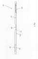
- FIG 3 shows the microfluidic cartridge 10 of Figure 1 seen from the side..
- the microfluidic cartridge 10 comprises a substrate 12 with five cavities in the form of channels 11.
- the channels 11 are provided in the form of grooves covered with a foil 11a.
- Each channel 11 is connected with an inlet 13 and at their opposite end the channels 11 are connected with a common sink 14.
- the inlet 13 has the shape of a well.
- the wall By pressing the flexible wall section 15 of the sink 14, the wall will be moved and air will be pressed out of the channels 11, and when the pressure is released the flexible wall section 15 will return to its initial position and a liquid sample arranged in the inlet 13 will be sucked into the channel 11 to a desired position.
- the liquid sample By further manipulating the flexible wall section the liquid sample can be drawn further into the channels 11 or it may be pulsated in the channels.
- the flexible wall section 15 may be manipulated to collect the sample in the sink and to re-flush the sample into the channels, if desired.
- the flexible wall section 15 thereby provides a simple and cheap method of controlling a liquid sample in the micro fluidic device.
- the micro fluidic cartridge also comprises an indent which provides a read out section 16 for the channels 11.
- the channels comprise a transparent window and the magnetic particles can be temporally immobilized using a not shown magnet.
- the magnet is mounted in the detector assembly which also includes a reading for reading signals through the read section 16.
- FIGS 4 and 5 show alternative embodiments of the microfluidic cartridge 20.
- microfluidic cartridge 20 is seen with two channels 21, which in one end is connected with an inlet 23 and in the opposite end connected with sinks 24.
- each chamber is connected with the channel and each chamber may comprise an analyte, which may react with a liquid sample which will fill the chambers when it passes from the inlet 23, through the channels 21 to the sink 24.
- the channels 21, the inlet 23, the sinks 24, and the chambers 27, 28 are formed as recesses in the substrate 22.
- the access to the channels 21, the sinks 24, and the chambers 27, 28 are closed by a foil 21a, so they are only accessible via the inlet 23.
- the chambers 27 and 28 are placed in pairs on each side of the channel 21.
- the chambers may comprise the same or different analytes.
- each pair along the channel may comprise the same analyte so the sample will be tested twice with same analyte, thereby improving the certainty of the measured results.
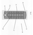
- the microfluidic cartridge 20 shown in Figure 4 may e.g. be able to measure with twelve different analytes, i.e. the microfluidic cartridge 20 comprises twelve pairs of chambers 27, 28 located along the channels 21.
- the analytes may be a combination of analytes, which may be measured with different means, such as optical, electrical or magnetic means.
- the analytes may e.g. be immobilized magnetic particles or immobilized enzymes functioning as color-forming reactants, which will react with the liquid sample, when the sample enters the chamber.
- FIG. 5 shows a microfluidic cartridge 20 which substantially corresponds to the microfluidic cartridge shown in Figure 4 .
- the sinks are omitted in this particular embodiment.
- the microfluidic cartridge comprises an inlet 23 connected with two channels 21, which are connected with pairs of chambers 27, 28 along the channels.
- the chambers 27 and 28 are transparent to light from a light source e.g. a multicolor-LED. As such the chambers 27 and 28 are suitable for use with optical detection means.
- microfluidic cartridge illustrated in Figure 5 is used as an example of some measurements which may be performed with the microfluidic detection system.
- Figure 6 shows an optical detection system in which an LED 30 emits a substantial monochromatic light beam towards a chamber in the microfluidic cartridge 20.
- the light beam bases the sample in the chamber and is transformed to a light beam 32 with different wavelength.
- the light beam 32 is detected by the CCD detector 35 below the microfluidic cartridge 20.
- Figure 7 shows another example in which the microfluidic cartridge 20 receives a light beam 31 emitted from the LED 30.
- the light beam 31 is reflected by the sample in the chamber of the microfluidic cartridge.
- the reflected light is divided into light with two different wavelengths 32 and 33 which are detected by the CCD detector 35 placed on the same side of the microfluidic cartridge 20 as the LED 30.
- Figure 8 shows yet another exampleof the detection system.
- the detection system utilizes a spectrometer 36 for detection of the light reflected from the sample in a chamber of the microfluidic cartridge 20.
- the light beam 31 is emitted from the LED 30 and reflected by the sample held in the microfluidic cartridge 20.
- the reflected light is reflected as light with three different wavelengths 32, 33 and 34.
- the reflected light is detected by the spectrometer 36 and the resulting curve is shown in the inserted box 37.
- Figure 9 illustrates an embodiment of the detection system. This is a system where an array or electrodes 38 send a current through one or more of the chambers in the microfluidic cartridge 20. Due to the resistance in the sample, the detection system will be able to detect the nature of the sample.
- FIG 10 illustrates the principles of a light tunnel.
- the light tunnel includes three LEDs 30a, 30b and 30 c, each emitting light with a wavelength which is different from the wavelengths of the other two LEDs.
- the LED 30a may emit light in the range: 610 ⁇ 760.
- the LED 30b may emit light in the range 570 ⁇ 590, and finally the LED 30c may emit light in the range: 450 ⁇ 500.
- Each LED is intended to emit light to one or more specific detection sites, and to avoid transmission of incident light to detection sites where it is not desired, the light tunnel is constructed with partition members 39 which will ensure that undesired transmission of incident light is avoided.
- each LED 30a, 30b and 30c is enclosed by partitions members 39, which will ensure that the light emitted from the LED only transmits light to the detection site for which the light is intended.
- the light tunnel makes it possible to transmit light through two or more detection sites simultaneously.
- the LEDs 30a, 30b and 30c transmit light simultaneously through three different detection sites on the microfluidic cartridge 20.
- the resulting light beams are detected by the CCD detector 35.
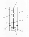
- FIG 11 shows an embodiment of a microfluidic cartridge 40 according to the invention.
- the the microfluidic cartridge 40 comprises an inlet 43 for introduction of a sample.
- the inlet 43 is connected with a channel 41 which in the opposite end is connected with a sink 44.
- a channel 41 which in the opposite end is connected with a sink 44.
- the channel 41 Along the length of the channel 41 are located two detection sites 47 for optical detection and further two detection sites 48 for electrical detection.
- the electrical detection sites 48 may comprise electrodes which are connected with connection pads 50 by means of electrical wiring 49.
- the electrical wiring may be printed on the substrate 42 of the the microfluidic cartridge 40.
- connection pads 50 may be connected with corresponding connection pads in the detection assembly and to an electrical reader, such as a voltmeter.
Description
- The invention relates to a microfluidic cartridge for performing a plurality of different assays and a a microfluidic detection system suitable for performing electrical assays of a sample using the microfluidic cartridge.
- Microfluidic detection systems and microfluidic cartridges of such systems are well known in the art. Such microfluidic detection system usually comprises a detector assembly and at least one microfluidic cartridge, where the microfluidic cartridge is shaped to hold a sample e.g. a liquid sample in a flow channel of the microfluidic cartridge. The microfluidic cartridge can be inserted into a slot of the detector assembly for optical analyses. Such microfluidic detection systems are usually used for performing analysis of liquids very fast and at relatively low cost. Often such microfluidic detection systems are used for high through put analysis. Due to development of standard analyses which can be performed at the doctor or even at a home of a patient, it is required that the general cost for the microfluidic detection system is relatively low.
- Many of the standard analysis require that the sample should be subjected to several tests using optical light sources having different wavelengths.
US 3,910,701 discloses an apparatus for measuring light reflectance, absorption and/or transmission having a plurality of light emitting diodes (LEDs) arranged to direct light emissions toward a test piece, with the various diodes being selected to emit light of different wavelengths and at least one light-responsive sensor disposed to receive light reflected and/or transmitted by the test piece and originating with each of the light-emitting diodes. - Electrical drive circuit means are provided for alternately or sequentially energizing the plurality of LEDs of different wavelengths, such that the reflected or transmitted light received by the sensor is a function of the various wavelengths of the respective LEDs. The plurality of LED sources and the light responsive sensor are mounted within a self-contained module, of size and shape similar to a camera lens, and the module is detachably connected to a portable housing for the instrument. In this manner, a number of different source modules may be provided for each detection site simply by moving the module.
-
US 7,791,728 discloses a microfluidic analysis system for optically analyzing a substance that includes a light source having a plurality of selectable single-wavelength light sources, a substance presentation member optically coupled to the light source, and an optical detection system associated with the substance presentation member. The light source and wavelength selection system include a light generating carousel having a plurality of single-wavelength light sources coupled thereto. The carousel can be rotated for position of the desired single-wavelength light source for a test. The microfluidic analysis system is suitable for completing an optical analysis on a millimeter or microliter scale volume of fluid due to the use of the multi-wavelength selector structure having multiple single-wavelength light sources such as light emitting diodes (LEDs) or lasers. -
US2013327957 discloses an apparatus and methods for performing flow cytometry on particles that undergo a Stokes-shift emission of radiation. An interrogation apparatus may be used to detect, sort, quantify, and/or qualify particles of interest that are carried in a sample of fluid. A microfluidic cassette is arranged to urge particles of interest through the interrogation aperture in a substantially single-file arrangement. The source of stimulation radiation is generally structured to emit radiation as a beam oriented for propagation of stimulation radiation in a Particular direction, such as though an interrogation aperture of a cassette. At least a first photodetector is disposed in an operable position to detect Stokes-shift emission radiation from a particle passing through the interrogation aperture. -
US2013258318 discloses an apparatus for, and a method of, characterizing a plurality of particles carried by a fluid that can be urged to move through a channel in a microfluidic cassette by combining data analysis of a first signal that is optically-based, and data analysis of a second signal that is electrically-based. Optically-based information is typically obtained by a digital image sensor. Electrically-based information can be obtained by direct measurement of impedance; sometimes in an arrangement operating under the Coulter principle. Data provided by exemplary characterization includes at least one of: volumetric cell count; viability percentage or ratio; particle type; and a particle size histogram. -
US 2013/327957 A1 discloses a microfluidic cassette comprising a five-layer structure for performing flow cytometry in which electrodes on a central interrogation layer made of a polymer perform an electrical measurement and the layers are optically transmissive to permit a fluorescence measurement to be performed. - A microfluidic detection system which can be applied for performing a plurality of analysis in a very fast and simple manner is provided.
- The microfluidic system can be applied for performing analysis of very high accuracy at a relatively low cost.
- The microfluidic detection system is stable and has a long durability.
- The object of the invention is to provide a microfluidic cartridge which is suitable for performing a plurality of different assays and which microfluidic cartridge advantageously can be applied as a part of the microfluidic detection system.
- These and other objects have been solved by the invention as defined in the claims and as described herein below.
- The invention is set out in the appended set of claims. References to "embodiments" which are not according to the invention as set out in the appended set of claims are to be understood as being for illustration purposes only.
- It has been found that the invention and embodiments thereof have a number of additional advantages, which will be clear to the skilled person from the following description.
- The microfluidic detection system is a very compact system which can be applied in a wide range of different analysis and where only minor amounts of liquid sample are required for each analysis. The test can be performed in a very fast way and accordingly the microfluidic detection system may be applied for high throughput analysis.
- The terms "test" and "analysis" are used interchangeably.
- The microfluidic detection system comprises a microfluidic cartridge and a detector assembly.
- The microfluidic cartridge comprises a first and a second side and at least one flow channel and at least one inlet to the one or more flow channels for feeding a liquid sample. The flow channel or flow channels comprises a plurality of detection cites comprising at least one electrical detection site comprising electrodes arranged for performing an electrochemical detection at the electrical detection site, and at least one optical detection site with a transparent window for optical readout at the optical detection site, wherein the microfluidic cartridge comprises a solid substrate with a channel shaped cavity and a polymer foil bonded to said solid substrate to form the at least one flow channel, wherein the foil is a polymer carrying the electrodes for the at least one electrical detection site and electrical transmission lines for reading out from the electrodes.
- The microfluidic detection system comprises a microfluidic cartridge and a detector assembly, the microfluidic cartridge comprises at least one flow channel, the flow channel(s) comprises at least one electrical detection site and an inlet to the flow channel(s) for feeding a liquid sample to the electrical detection site, the microfluidic cartridge comprises a solid substrate with channel shaped cavity and a polymer foil bonded to the solid substrate to form the at least one flow channel, electrodes, electrical transmission lines and connection pads are arranged for performing an electrochemical detection at the electrical detection site, wherein the foil is a polymer carrying the electrodes and the electrical detection site.
- The detector assembly comprises a slot for inserting the microfluidic cartridge and at least one electrical reader for reading out electrical signals out from the electrical detection site(s) via the connection pads when the cartridge is inserted to a first or second predetermined position into the slot, the predetermined positions of the microfluidic cartridge are determined by projecting flanges arranged on the microfluidic cartridge and cavities arranged on the detector assembly at selected positions or projecting flanges arranged on the detector assembly and cavities arranged on the microfluidic cartridge at the selected positions, which engage or snap into place to temporarily positioning the microfluidic cartridge in the detector assembly at one of the first and the second predetermined positions, the projecting flanges and cavities comprises a first set of projecting flanges and cavities which correspond to the first predetermined position and the projecting flanges and cavities comprises a second set of projecting flanges and cavities which correspond to the second predetermined position.
- The term "optical detection site" means a part of one of the one or more flow channels of the microfluidic cartridge with a transparent window and comprising or constructed to comprise a sample part subjected to the optical analysis via the transparent window. An optical detection site is advantageously a relatively small part of the at least one flow channel, preferably in the form of section of the at least one flow channel and/or a chamber preferably in fluid connection to at least one of the at least one flow channel.
- The optical detection site may be determined as the site irradiated by the light beams and from which the signals are directed to the optical reader.
- The term "optical detection site" may be at least one of the first optical detection site.
- The term "optical detection site" used in singular should also be interpreted to include the plural form of the "optical detection sites", unless otherwise specified.
- The term "first optical detection site" is meant to denote optical detection site(s) which is to be illuminated from the first fixed light source.
- The term "light beam" is herein used to mean a directional projection of light emitted from the Led. The light beams are not continuous but may have a desired duration sufficient to perform the desired analysis. A suitable duration may e.g. be up to 10 seconds, such as from about 1 ms to about 5 seconds.
- The term "rays of light" is used to denote a part of the light beam i.e. the light beam comprises a plurality of rays.
- The slot in the detector assembly is adapted to the microfluidic cartridge. Normally the microfluidic detection system will comprise a plurality of microfluidic cartridges which one after the other may be inserted into the detector assembly for performing at least one analysis.
- The slot in the detector assembly may in an embodiment be adapted to microfluidic cartridges of different shapes and/or sizes.
- The microfluidic cartridge may advantageously be at least partly of transparent glass or polymer. In a preferred embodiment the microfluidic cartridge comprises a polymer substrate having one or more channel shaped cavities which are covered by a foil which in at least the optical detection site is transparent to thereby form the flow channel or flow channels.
- In an embodiment the cartridge comprises one or more integrated lenses and/or mirrors arranged in or adjacent the optical detection site. The one or more integrated lenses and/or mirrors may act to direct, and/or focus the beams to the optical detection site.
- One or more integrated lenses and/or mirrors and/or other optical components may be arranged at any desired position in the microfluidic detection system in order to guide the beams, to direct the beams, to confine the beams, to focus the beams and/or to collimate the beams or in other ways manipulate the beams.
- In an embodiment the flow channel or flow channels of the microfluidic cartridge comprises a plurality of detection sites configured for performing a plurality of different assays. The detection sites may comprise any type of detection sites e.g. as described below.
- The plurality of detection cites comprises at least one electrical detection site. An electrical detection site is a site in the flow channel(s) configured for reading out an electrical signal via electrodes. Therefore the electrical detection site need not be transparent.
- The electrical detection site comprises electrodes arranged for performing an electrochemical detection at the electrical detection site. The electrodes comprise electrical wires connected to microfluidic cartridge connection pads.
- The electrical wires can be in the form of any type of electrical transmission lines, such as printed metal lines. Other preferences are described below.
- The connection pads of the microfluidic cartridge are configured for providing read out electric contact to the detector assembly.
- The detector assembly comprises at least one electrical reader for reading out electrical signals out from the electrical detection site(s) via the connection pads.
- In an embodiment the electrical reader comprises a voltmeter electrically connected to voltmeter connection pads arranged in the slit such that when the microfluidic cartridge is inserted into the slot the microfluidic cartridge connection pads are in electrical connection with the voltmeter connection pads. Thereby the microfluidic cartridge can in a simple way be accurately positioned relative to the detector assembly e.g. further making use of the click arrangement described above.
- Advantageously the detector assembly further comprises at least one output interface such as a display and/or a printer and a processor. The processor may be any kind of processor preferably a programmable computer which is integrated into the detector assembly. In an embodiment the detector assembly is connected to a computer via a wire or via wireless connection.
- The detector assembly may for example be connected to a central database comprising patient journals, and by identifying the patient e.g. by scanning a barcode or a chip related to the patient e.g. a bar code on a wrist on the patient or a chip in the patient ensuring that the result is entered into the patient journals in the central database or the detector assembly may receive instructions from the patient journal concerning which assays are to be performed on the sample from the patient.
- The processer may be programmed with software for performing one or more desired assays.
- In an embodiment the detector assembly is programmed to perform a multiplexing of the read out signals.
- In an embodiment the microfluidic cartridge comprises a machine readable code comprising instructions about assays to be performed using the cartridge and the detector assembly comprises a code reader for reading the machine readable code and feeding the instructions about the assays to be performed to the processor, wherein the processor is programmed to control at least one of the reader(s) and the output interface at least partly based on instructions obtained from the machine readable code, preferably the at least one reader is at least one of the optical reader and the electrical reader.
- The bar code may be any kind of bar code such as a 1D, a 2D or a 3D bar code.
- In an embodiment the detector assembly comprises a plurality of microfluidic cartridges comprising different bar codes coding for different assays.
- Advantageously the respective bar codes of the microfluidic cartridges each code for performing read out of a predetermined number of the detection sites.
- The bar code system may for example be used to indicate which assays a client should have access to and/or which dispatch sites a client should access to read out from.
- Thereby microfluidic cartridges prepared for several different assays could be sold with different bar codes, where respective barcodes codes for allowing use of respective assays. Thereby it is not required to make different microfluidic cartridges for different assays or assay combinations and mass production of one or a few types of microfluidic cartridges for a plurality of different assays instead of making many different types of microfluidic cartridge reduces cost significantly.
- In an embodiment at least one of the microfluidic cartridges comprises a bar code coding for performing read outs from only some of the detection sites.
- The detector assembly is advantageously programmed using suitable software. The software advantageously comprises a central database which can be used in analyzing the resulting detection e.g. for calibration against tests performed on samples with known compositions.
- In an embodiment the software comprises a database having data identifying preselected diseases and if a patient has one of these diseases it can be identified when performing assays on a sample from this patients. Thereby outbreaks of infectious diseases for example in a region can relatively fast be identified.
- In an embodiment the software comprises a database having data identifying preselected pathogen components, such as pathogen microorganisms for which an assay can be performed, by performing the assay the concentration of such pathogen components in a sample from a patient can be determined very fast, and during treatment of the patient monitoring of treatment progress compared to other similar patients can be performed.
- In an embodiment the software comprises a program for performing built-in decision-tree for multiple assay results thereby providing an adaptive response depending on actual number of assays run on a sample.
- In an embodiment batch information of the microfluidic cartridge is in a central database and the detector assembly can access this information via the barcode or via a batch number. Thereby limited data on the microfluidic cartridge are required.
- The detector assembly may preferably comprise a temperature controlling element arranged to be in contact with the microfluidic cartridge in the slot, and preferably adjacent to at least one of the detection sites when the microfluidic cartridge is inserted into the slot of the detector assembly.
- Such a temperature controlling element can for example comprise a peltier element, a thin film heating element and/or other resistive heating elements.
- In an embodiment the detector assembly is constructed to perform a pumping effect in the flow channel of the microfluidic cartridge by alternately applying heating and cooling air in a pumping chamber of the microfluidic cartridge where the pumping chamber is in fluid contact with the flow channel. By alternately applying heating and cooling air in the pumping chamber, the pressure in the pumping chamber will alternately increase and decrease thereby resulting in a pumping effect.
- In an embodiment the detector assembly comprises a movable pin for actuating a liquid sample in the flow channel. The microfluidic cartridge which can be applied in this embodiment comprises a flexible membrane e.g. in the form of a foil, covering a part of the flow channel or a chamber in fluid connection with the flow channel and the pin is arranged to be pressed into the channel or chamber to perform a pumping effect.
- Such pumping effect may be applied to fill up desired areas e.g. chambers of the flow channel and/or to perform a mixing of liquids and solids.
- In an embodiment the detector assembly comprises an actuator e.g. in the form of a movable pin for temporarily depressing and optionally closing the flow channel.
- The actuator is e.g. a step motor driven actuator for example such as described in
WO2012016107 . - The actuator may form a membrane pump, which in combination with hydraulic resistance can ensure filling of one or more chambers, such as all chambers.
- In use the liquid sample is fed to the microfluidic cartridge and the microfluidic cartridge is inserted into the slot of the detector assembly e.g. manually or using a robot e.g. a cassette-robot function.
- Preferred micro fluidic devices will be described further below.
- The term "liquid sample" means any liquid containing sample including liquid sample comprising solid parts, such as dispersions and suspensions. The sample comprises liquid at the time of performing the method.
- In principle any liquid sample can be applied, including but not limited to liquid samples comprising particles, such as dispersed particles. In one embodiment the liquid sample is crushed food or tissue optionally blended with water or it may be an extract thereof. Thus, the microfluidic detection system can for example be applied for performing quantitative and/or qualitative tests on tissue, vegetables, meat and etc.
- In an embodiment the liquid sample comprises human or animal faeces e.g. in an aqueous suspension.
- In an embodiment the liquid sample comprises waste water or water from a nature source e.g. a lake or a river.
- In an embodiment the liquid sample comprises markers such a fluorophores preferably bonded to a target component toward which at least one assay is to be performed. The fluorophores may in an embodiment be bonded to a magnetic particle.
- Generally it is desired to select fluorophores with a relatively specific emission wavelength and energy for a simpler qualitative or quantitative determination of the target component. In particular it is desired that the emission wavelength is relatively specific, i.e. it should preferably have a wavelength band which in the method of determination is sufficiently narrow to be distinguished from other emissions.
- The term "relatively specific wavelength" means that the wavelength can be distinguished from other emitting wavelengths in the test.
- In particular in situations where there are several different fluorophores and optionally several target components it is preferred that the fluorophores have relatively specific emission wavelengths such that emission from the respective fluorophores can be distinguished from each other.
- The fluorophores can be any type of fluorophores which can be configured to bind to the capture sites of the magnetic particles. Fluorophores are well known to the skilled person and are commercially available.
- Examples of quantum dots are described in
US 7498177 and the quantum dots available from Life Technologies Europe BV. include more than 150 different product configurations with emission wavelength spanning in a broad wavelength range for examples quantum dots with the respective emission wavelengths: 525, 545, 565, 585, 605, 625, 655 and IR 705 and 800 nm. In an embodiment StreptAvidin, Biotin, antibodies and a number of different functionalities have been conjugated in the Invitrogen/life Technologies portfolio of Quantum dot products. - Examples of quantum dots also include quantum dots available from Ocean NanoTech, Springdale, Arkansas 72764, including more than 40 different product configurations with emission wavelength spanning in nm and a functionalized outer core of PEG or other biological compatible coating, for example with the respective emission wavelengths: 530, 550, 580, 590, 600, 610, 620 and 630 nm. The quantum dots from Ocean NanoTech include quantum dots with different functional groups e.g. amine, COOH, phenylboronic acid (PBA), as well as quantum dots with amphiphilic polymer and PEG coating. Other examples of quantum dots available from Ocean NanoTech are quantum dots with a sole core e.g. provided in toluene and with only an octadecylamine coat or with amphiphilic polymer and PEG coating.
- In an embodiment the fluorophores are quantum dots or aromatic probes and/or conjugated probes, such as fluorescein, derivatives of benzene, metal-chalcogenide fluorophores or combinations thereof.
- The fluorophores may in an embodiment be configured to bind to a selected capture sites e.g. within an optical detection site of the microfluidic cartridge.
- The invention relates to a microfluidic cartridge according to the appended claims. The microfluidic cartridge is suitable for being a part of the microfluidic detection system. The microfluidic cartridge of the invention can also be used alone or together with prior art detector assemblies.
- The microfluidic cartridge of the invention is designed for performing a plurality of different assays. The cartridge comprises at least one flow channel and an inlet to the flow channel(s) for feeding a liquid sample. The flow channel(s) comprises a plurality of detection cites comprising at least one electrical detection site comprising electrodes arranged for performing an electrochemical detection at the electrical detection site, and at least one optical detection site with a transparent window for optical readout at the optical detection site.
- Heretofore it has never been suggested to provide a microfluidic cartridge which can be applied for simultaneously performing optical and electrical red outs from the same sample. The microfluidic detection system provides a new concept which opens up for a new range of combined assays to be performed very fast and on the same sample. This microfluidic cartridge is both time saving and furthermore the results obtained may be more accurate because the electrical and the optical test can be performed at the same time and at the same sample.
- Advantageously the cartridge comprises a plurality of electrical detection sites and/or a plurality of optical detection sites.
- Preferably each of the one or more optical detection sites is in the form of a chamber having a cross sectional area which is at least about 25 %, such as at least about 50 %, such as at least 100 % larger than a cross sectional area of the flow channel leading to the chamber.
- The respective chambers may have equal or different size.
- Advantageously one or more of the optical detection sites comprise a reagent, preferably all of the optical detection sites comprise a reaction agent. The reagent can in principle be any reagent, such as the reagents known from prior art.
- In an embodiment at least one optical detection site of the cartridge is an absorption optical detection site configured for absorption detection, the absorption optical detection site preferably comprises at least one reagent selected from agglutination reagents, coagulation reagents, an antibody and/or an antigen.
- In an embodiment at least one optical detection site of the cartridge is a colorimetric detection site configured for colorimetric detection, preferably the colorimetric detection site comprises at least one reagent selected from color-forming reagents.
- The color-forming reagent can be any kind of reagent that induces a color change upon reaction with a target to be tested for using the microfluidic cartridge.
- Targets that can be subjects to a colorimetric detection e.g. by being converted chemically to a colored product via a color-producing reaction include enzyme substrates and co-factors. Non-limiting examples of such targets include glucose, cholesterol, and triglycerides. In particular, levels of total cholesterol (i.e., the sum of free and esterified cholesterol) in a body fluid can be spectrophotometrically measured by well-known color-forming assays by reacting the fluid with color-forming reactants including cholesterol esterase, cholesterol oxidase, an oxidizable dye such as n,n-bis(4-sulfobutyl)-3-methylaniline, disodium salt (TODB), 4-aminoantipyrine, and horse radish peroxidase.
- A vast number of color-forming reactants may be used for catalyzing the formation of colored products. Examples of such color-forming reactants include alanine aminotransferase (ALT) and aspartate aminotransferase. Alanine aminotransferase (ALT) is a reactant indicative of liver function. Other suitable color-forming reactants include alphaketoglutarate, pyruvate oxidase, an oxidizable dye such as N,N-Bis(4-sulfobutyl)-3-methylaniline, disodium salt (TODB), 4-aminoantipyrine, and horse radish peroxidase.
- Other targets which may be detected via a color-producing colorimetric detection comprise targets found by immunoassays, such as an enzyme-linked immunosorbent assay (ELISA). In a typical ELISA, a target is specifically bound by an antibody, which in turn is detected by a secondary, enzyme-linked antibody. The linked enzyme (the color-forming reactants) catalyzes a color-producing reaction. Such enzymes include but are not limited to beta -galactosidase, alkaline phophatase, and horse radish peroxidase.
- The choice of suitable color-forming reactants will depend on the particular target being examined. In general, any color-forming reactants capable of reacting with a target either directly or indirectly to generate colored products is suitable for use in the microfluidic cartridge of the present invention.
- In an embodiment at least one optical detection site of the cartridge is a spectroscopic detection site configured for spectroscopic detection, preferably the spectroscopic detection site comprises at least one reagent selected from markers e.g. fluorophores such as the fluorophores described above.
- In an embodiment the cartridge comprises a solid substrate with at least one channel shaped cavity for forming the flow channel(s) with chambers for dispatch sites and optionally additional chambers e.g. pumping chamber and a sink section such as described in
WO2012016107 . - A flexible foil is bonded to the solid substrate to form the flow channel(s). The foil is preferably bonded to the solid substrate by welding.
- In an embodiment the foil is a semi permeable foil for capillary venting e.g. evaporation of selected gasses.
- In an embodiment the solid substrate is carrying the electrodes for the at least electrical detection site and electrical transmission lines for reading out from the electrodes. The electrodes and electrical transmissions lines may advantageously be printed electrodes on molded base for increased robustness in mass production.
- The foil is a polymer carrying the electrodes for the at least electrical detection site and electrical transmission lines for reading out from the electrodes.
- In an embodiment electrodes are provided on both sides of the foil, preferably with through holes to ease connectivity and to improve robustness of the electrodes.
- Advantageously the electrodes and/or the electrical transmission lines are applied by vapor deposition, sputtering and/or printing, preferably at least one of the electrodes and/or the electrical transmission lines are printed.
- The printing can be screen printing, gravure printing or transfer printing.
- In an embodiment at least a part of the electrical transmission lines are embedded in the polymer, optionally the foil comprises a cover polymer film laminated onto the at least a part of the electrical transmission lines to thereby embed at least the part of the electrical transmission lines.
- The polymer foil may for example comprise a thermoplastic polymer, preferably selected from Polystyrene (PS), Polycarbonate (PC) or polyimide (PI).
- The microfluidic cartridge can be produced in any suitable materials, e.g. the materials used for prior art microfluidic cartridges.
- The microfluidic cartridge may for example be produced from one or more elements made from polymers, such as polymers selected from cyclic oleofin copolymers (COC), acrylonitrile-butadiene-styrene copolymer, polycarbonate, polydimethyl-siloxane (PDMS), polyethylene (PE), polymethylmethacrylate (PMMA), polymethylpentene, polypropylene, polystyrene, polysulfone, polytetra-fluoroethylene (PTFE), polyurethane (PU), polyvinylchloride (PVC), polyvinylidene chloride (PVDC), polyvinylidine fluoride, styrene-acryl copolymers polyisoprene, polybutadiene, polychloroprene, polyisobutylene, poly(styrene-butadiene-styrene), silicones, epoxy resins, Poly ether block amide, polyester, acrylonitrile butadiene styrene (ABS), acrylic, celluloid, cellulose acetate, ethylene-vinyl acetate (EVA), ethylene vinyl alcohol (EVAL), fluoroplastics, polyacetal (POM), polyacrylates (acrylic), polyacrylonitrile (PAN) polyamide (PA), polyamide-imide (PAI), polyaryletherketone (PAEK), polybutadiene (PBD), polybutylene (PB), polybutylene terephthalate (PBT), polyethylene terephthalate (PET), polycyclohexylene dimethylene terephthalate (PCT), polyketone (PK), polyester/polythene/polyethene, polyetheretherketone (PEEK), polyetherimide (PEI), polyethersulfone (PES), polyethylenechlorinates (PEC), polyimide (PI), polylactic acid (PLA), polymethylpentene (PMP), polyphenylene oxide (PPO), polyphenylene sulfide (PPS), polyphthalamide (PPA), and mixtures thereof.
- Prefered polymers comprise a polyimide, e.g. a phenylene-pyromellitimide such as poly(4,4'-oxodiphenylene-pyromellitimide e.g. Kapton®.
- In an embodiment the microfluidic cartridge is manufactured by providing a rigid substrate comprising one or more channels and optional cavities and/or holes and covering the one or more channels and optional cavities and/or holes with one or more films. The rigid substrate is advantageously produced by injection molding but other molding methods may also be applied. The film may be a polymer or a metal film or a layered film comprising polymer and/or metal e.g. a polymer coated metal film or a metal sputtered polymer film.
- At least one of the substrate and the film is transparent to at least one wavelength, preferably within the visible area. Advantageously at least one of the substrate and the film is transparent to at least one of the different light beams of the detector assembly it is supposed to be used together with.
- The film may advantageously be welded to the substrate. Gluing may also be provided.
- By providing the microfluidic cartridge from a substrate and a film as described the microfluidic cartridge will have a substrate side and a film side.
- It should be emphasized that the term "comprises/comprising" when used herein is to be interpreted as an open term, i.e. it should be taken to specify the presence of specifically stated feature(s), such as element(s), unit(s), integer(s), step(s) component(s) and combination(s) thereof, but does not preclude the presence or addition of one or more other stated features.
- All features of the inventions including ranges and preferred ranges can be combined in various ways within the scope of the invention, unless there are specific reasons for not to combine such features.
- The invention will be explained more fully below in connection with a preferred embodiment and with reference to the drawings in which:
-
FIG. 1 shows an example of a detector assembly, -
FIG. 2 shows an example of a microfluidic cartridge, -
FIG. 3 shows the microfluidic cartridge offig. 2 in a side view, -
FIG. 4 shows an alternative embodiment of the microfluidic cartridge, -
FIG. 5 shows yet another embodiment of the microfluidic cartridge, -
FIG. 6 shows detection with LED and CCD, -
FIG. 7 shows alternative detection with LED and CCD, -
FIG. 8 shows detection with spectrometer, -
FIG. 9 shows electrical detection, -
FIG. 10 shows a light tunnel, and -
FIG. 11 shows a microfluidic cartridge adapted for electrical detection. - The figures are schematic and only intended to show the principles of the invention and may be simplified for clarity. Throughout, the same reference numerals are used for identical or corresponding parts.
- Further scope of applicability of the present invention will become apparent from the detailed description given hereinafter. However, it should be understood that the detailed description and specific examples, while indicating preferred embodiments of the invention, are given by way of illustration only, since various changes and modifications within the scope of the invention will become apparent to those skilled in the art from this detailed description.
- The invention is defined by the features of the independent claim(s). Preferred embodiments are defined in the dependent claims. Any reference numerals in the claims are intended to be non-limiting for their scope.
-
Figure 1 shows adetector assembly 1. The detector assembly comprises ascreen 2, which is used for visually setting the detector assembly and visually display the result of measurements performed on thedetector assembly 1. Thedetector assembly 1 comprisescontrol buttons 3 which are used for setting and operating the detector assembly. The detector assembly also comprises means for connection with other hardware, such as a computer or printer. - The
detector assembly 1 also comprises aslot 4 in which a microfluidic cartridge may be inserted. The microfluidic cartridges are described in further details below. The interior of the detector assembly comprises means for keeping the microfluidic cartridge in a fixed position when the cartridge is inserted into the slot. - Thus, when a microfluidic cartridge comprising a sample of interest is inserted into the
slot 4 of thedetector assembly 1, the detector assembly may perform measurements on the sample. The measurements may e.g. be optical measurements such photometric or colorometric measurement. It may also be measurements based on a charge-coupled device or magnetic measurements. -
Figure 2 shows a microfluidic cartridge comprising asubstrate 12 with five cavities in the form ofchannels 11. Eachchannel 11 comprises aninlet 13 and asink 14 with a not shown flexible wall section. - The
microfluidic cartridge 10 also comprises an indent, which provides a read outsection 16 for thechannels 11, where the channels comprise a transparent window and where magnetic particles may be temporally immobilized using a not shown magnet. - In this embodiment each
channel 11 comprises temporally immobilized magnetic particles and temporally immobilized fluorophores. The microfluidic device is divided intozones comprising zone 0 which is the inlet zone,zone 1 andzone 2 which comprise temporally immobilized fluorophores and magnetic particles 17 arranged such that they do not react until they are in contact with the liquid sample,zone 3 which is the read out zone andzone 4 which is the sink zone. - In an
embodiment zone 1 comprises temporally immobilized fluorophores andzone 2 comprises temporally immobilized magnetic particles. - In an
embodiment zone 1 comprises temporally immobilized magnetic particles andzone 2 comprises temporally immobilized fluorophores. - The
microfluidic cartridge 10 may comprise several subzones ofzone 1 andzone 2, if desired. - In use a liquid sample is fed to the
inlet 13, the sample is sucked intozone 1 of the channels using the flexible wall section, which will later be described in more details. Optionally the liquid sample is pulsated inzone 1 to dissolve or re-suspend the immobilized elements 17 inzone 1. Thereafter the liquid sample is drawn further into thechannels 11 tozone 2 for dissolving or resuspending the immobilized elements 17 inzone 2. After a preselected incubation time the liquid sample is drawn fully into thesinks 14. The magnetic particles are immobilized in the read outzone 3. Moreover, if desired, the liquid sample can be reintroduced into thechannels 11 by using the flexible wall of thesink 14 and the immobilized magnetic particles can be flushed using the liquid sample to remove not immobilized fluorophores and other elements that could potentially provide noise. -
Figure 3 shows themicrofluidic cartridge 10 ofFigure 1 seen from the side.. - The
microfluidic cartridge 10 comprises asubstrate 12 with five cavities in the form ofchannels 11. Thechannels 11 are provided in the form of grooves covered with afoil 11a. Eachchannel 11 is connected with aninlet 13 and at their opposite end thechannels 11 are connected with acommon sink 14. Theinlet 13 has the shape of a well. - By pressing the
flexible wall section 15 of thesink 14, the wall will be moved and air will be pressed out of thechannels 11, and when the pressure is released theflexible wall section 15 will return to its initial position and a liquid sample arranged in theinlet 13 will be sucked into thechannel 11 to a desired position. By further manipulating the flexible wall section the liquid sample can be drawn further into thechannels 11 or it may be pulsated in the channels. Finally theflexible wall section 15 may be manipulated to collect the sample in the sink and to re-flush the sample into the channels, if desired. Theflexible wall section 15 thereby provides a simple and cheap method of controlling a liquid sample in the micro fluidic device. - The micro fluidic cartridge also comprises an indent which provides a read out
section 16 for thechannels 11. In the read outsections 16 of thechannels 11, the channels comprise a transparent window and the magnetic particles can be temporally immobilized using a not shown magnet. The magnet is mounted in the detector assembly which also includes a reading for reading signals through theread section 16. -
Figures 4 and5 show alternative embodiments of themicrofluidic cartridge 20. - In
figure 4 themicrofluidic cartridge 20 is seen with twochannels 21, which in one end is connected with aninlet 23 and in the opposite end connected withsinks 24. - Along the two
channels 21 a number ofchambers inlet 23, through thechannels 21 to thesink 24. - The
channels 21, theinlet 23, thesinks 24, and thechambers substrate 22. The access to thechannels 21, thesinks 24, and thechambers foil 21a, so they are only accessible via theinlet 23. - The
chambers channel 21. The chambers may comprise the same or different analytes. For example each pair along the channel may comprise the same analyte so the sample will be tested twice with same analyte, thereby improving the certainty of the measured results. Thus, themicrofluidic cartridge 20 shown inFigure 4 may e.g. be able to measure with twelve different analytes, i.e. themicrofluidic cartridge 20 comprises twelve pairs ofchambers channels 21. The analytes may be a combination of analytes, which may be measured with different means, such as optical, electrical or magnetic means. Thus, the analytes may e.g. be immobilized magnetic particles or immobilized enzymes functioning as color-forming reactants, which will react with the liquid sample, when the sample enters the chamber. -
Figure 5 shows amicrofluidic cartridge 20 which substantially corresponds to the microfluidic cartridge shown inFigure 4 . However, the sinks are omitted in this particular embodiment. When a liquid sample is placed in theinlet 23 it will flow into thechannels 21 and thechambers - Consequently, the microfluidic cartridge comprises an
inlet 23 connected with twochannels 21, which are connected with pairs ofchambers chambers chambers - In the following
Figures 6 to 9 the microfluidic cartridge illustrated inFigure 5 is used as an example of some measurements which may be performed with the microfluidic detection system. -
Figure 6 shows an optical detection system in which anLED 30 emits a substantial monochromatic light beam towards a chamber in themicrofluidic cartridge 20. The light beam bases the sample in the chamber and is transformed to alight beam 32 with different wavelength. Thelight beam 32 is detected by theCCD detector 35 below themicrofluidic cartridge 20. -
Figure 7 shows another example in which themicrofluidic cartridge 20 receives alight beam 31 emitted from theLED 30. Thelight beam 31 is reflected by the sample in the chamber of the microfluidic cartridge. The reflected light is divided into light with twodifferent wavelengths CCD detector 35 placed on the same side of themicrofluidic cartridge 20 as theLED 30. -
Figure 8 shows yet another exampleof the detection system. In this embodiment the detection system utilizes aspectrometer 36 for detection of the light reflected from the sample in a chamber of themicrofluidic cartridge 20. Thelight beam 31 is emitted from theLED 30 and reflected by the sample held in themicrofluidic cartridge 20. The reflected light is reflected as light with threedifferent wavelengths spectrometer 36 and the resulting curve is shown in the insertedbox 37. -
Figure 9 illustrates an embodiment of the detection system. This is a system where an array orelectrodes 38 send a current through one or more of the chambers in themicrofluidic cartridge 20. Due to the resistance in the sample, the detection system will be able to detect the nature of the sample. -
Figure 10 illustrates the principles of a light tunnel. The light tunnel includes threeLEDs LED 30a may emit light in the range: 610<λ<760. TheLED 30b may emit light in the range 570<λ<590, and finally theLED 30c may emit light in the range: 450<λ<500. - Each LED is intended to emit light to one or more specific detection sites, and to avoid transmission of incident light to detection sites where it is not desired, the light tunnel is constructed with
partition members 39 which will ensure that undesired transmission of incident light is avoided. - Thus, each
LED partitions members 39, which will ensure that the light emitted from the LED only transmits light to the detection site for which the light is intended. - The light tunnel makes it possible to transmit light through two or more detection sites simultaneously. As seen in the embodiment of
Figure 10 , theLEDs microfluidic cartridge 20. The resulting light beams are detected by theCCD detector 35. -
Figure 11 shows an embodiment of amicrofluidic cartridge 40 according to the invention. The themicrofluidic cartridge 40 comprises aninlet 43 for introduction of a sample. Theinlet 43 is connected with achannel 41 which in the opposite end is connected with asink 44. Along the length of thechannel 41 are located twodetection sites 47 for optical detection and further twodetection sites 48 for electrical detection. - The
electrical detection sites 48 may comprise electrodes which are connected withconnection pads 50 by means ofelectrical wiring 49. The electrical wiring may be printed on thesubstrate 42 of the themicrofluidic cartridge 40. - The
connection pads 50 may be connected with corresponding connection pads in the detection assembly and to an electrical reader, such as a voltmeter. - The figures only illustrate a limited number of embodiments according the invention, and the full scope of the invention is defined in the claims. However, it is clear that several combinations are possible and the optical detection may be combined with magnetic and/or electrical detection.
Claims (8)
- A microfluidic cartridge for performing a plurality of different assays, the cartridge (40) comprising at least one flow channel (41) and an inlet (43) to the flow channel for feeding a liquid sample to the flow channel (41), the flow channel comprising a plurality of detection sites (47, 48) comprising at least one electrical detection site (48) comprising electrodes arranged for performing an electrochemical detection at the electrical detection site (48), and at least one optical detection site (47) with a transparent window for optical readout at the optical detection site (47), wherein the microfluidic cartridge (40) comprises a solid substrate with a channel shaped cavity therein and a polymer foil bonded to said solid substrate to cover the channel shaped cavity so as to define the at least one flow channel (41) between the polymer foil and the substrate and so as to define the inlet, wherein the at least one electrical detection site (48) and the at least one optical detection site (47) are located in said at least one flow channel (41) and wherein said foil is a polymer carrying the electrodes for the at least one electrical detection site (48) and carrying electrical transmission lines (49) for reading out from the electrodes.
- The microfluidic cartridge of claim 1, wherein at least one the electrodes or at least one of the electrical transmission lines (49) is printed.
- The microfluidic cartridge of claim 1 or claim 2, wherein electrodes are located on both sides of the foil.
- The microfluidic cartridge of claim 1 or claim 2, wherein at least a part of the electrical transmission lines (49) are embedded in the polymer foil.
- The microfluidic cartridge of any one of claims 1-4, wherein the cartridge comprises connection pads (50) configured for being connected to connection pads of a voltmeter, the electrodes are connected to the connection pads via the electrical transmission (49) lines and the electrodes are located for transmitting a current through a liquid sample located at the electrical detection site (48).
- A microfluidic detection system comprising a microfluidic cartridge according to any one of the preceding claims and a detector assembly, the detector assembly comprises a slot for inserting the microfluidic cartridge and at least one electrical reader for reading out electrical signals out from the electrical detection site(s) (48) via said connection pads (50) when said cartridge (40) is inserted to a first or second predetermined position into said slot, said predetermined positions of said microfluidic cartridge (40) are determined by projecting flanges arranged on the microfluidic cartridge and cavities arranged on the detector assembly at selected positions or projecting flanges arranged on the detector assembly and cavities arranged on the microfluidic cartridge at the selected positions, which engage or snap into place to temporarily positioning the microfluidic cartridge (40) in the detector assembly at one of the first and the second predetermined positions, said projecting flanges and cavities comprises a first set of projecting flanges and cavities which correspond to the first predetermined position and said projecting flanges and cavities comprises a second set of projecting flanges and cavities which correspond to the second predetermined position.
- The microfluidic detection system of claim 6, wherein said electrical reader comprises a voltmeter electrically connected to voltmeter connection pads located in the slit, said connection pads (50) of the cartridge (40) are in electrical connection with the voltmeter connection pads when inserted into the slit at one of the first and the second predetermined positions.
- The microfluidic detection system of claim 7, wherein the electrodes are connected to the connection pads of the cartridge (50) via the electrical transmission lines (49) and the electrodes are located for transmitting a current through a liquid sample located at the electrical detection site (48) when said connection pads of the cartridge are in electrical connection with the voltmeter connection pads when inserted into the slit at one of the first and the second predetermined positions.
Applications Claiming Priority (3)
| Application Number | Priority Date | Filing Date | Title |
|---|---|---|---|
| DKPA201470363 | 2014-06-18 | ||
| EP15810324.2A EP3158317B8 (en) | 2014-06-18 | 2015-06-15 | A microfluidic detection system |
| PCT/DK2015/050166 WO2015192855A1 (en) | 2014-06-18 | 2015-06-15 | A microfluidic detection system and a microfluidic cartridge |
Related Parent Applications (2)
| Application Number | Title | Priority Date | Filing Date |
|---|---|---|---|
| EP15810324.2A Division EP3158317B8 (en) | 2014-06-18 | 2015-06-15 | A microfluidic detection system |
| EP15810324.2A Division-Into EP3158317B8 (en) | 2014-06-18 | 2015-06-15 | A microfluidic detection system |
Publications (2)
| Publication Number | Publication Date |
|---|---|
| EP3623794A1 EP3623794A1 (en) | 2020-03-18 |
| EP3623794B1 true EP3623794B1 (en) | 2022-03-02 |
Family
ID=54934895
Family Applications (2)
| Application Number | Title | Priority Date | Filing Date |
|---|---|---|---|
| EP15810324.2A Active EP3158317B8 (en) | 2014-06-18 | 2015-06-15 | A microfluidic detection system |
| EP19198299.0A Active EP3623794B1 (en) | 2014-06-18 | 2015-06-15 | A microfluidic detection system and a microfluidic cartridge |
Family Applications Before (1)
| Application Number | Title | Priority Date | Filing Date |
|---|---|---|---|
| EP15810324.2A Active EP3158317B8 (en) | 2014-06-18 | 2015-06-15 | A microfluidic detection system |
Country Status (12)
| Country | Link |
|---|---|
| US (2) | US10307754B2 (en) |
| EP (2) | EP3158317B8 (en) |
| JP (2) | JP6603675B2 (en) |
| KR (2) | KR102407905B1 (en) |
| CN (2) | CN106662522B (en) |
| AU (2) | AU2015276638B2 (en) |
| BR (1) | BR112016029490B1 (en) |
| CA (2) | CA2951959A1 (en) |
| ES (2) | ES2910383T3 (en) |
| MX (2) | MX2016016828A (en) |
| PT (2) | PT3623794T (en) |
| WO (1) | WO2015192855A1 (en) |
Families Citing this family (13)
| Publication number | Priority date | Publication date | Assignee | Title |
|---|---|---|---|---|
| CN110579435B (en) | 2012-10-15 | 2023-09-26 | 纳诺赛莱克特生物医药股份有限公司 | System, apparatus and method for particle sorting |
| TWI789343B (en) * | 2016-02-01 | 2023-01-11 | 丹麥商碩騰丹麥有限公司 | A microfluidic assay system, a microfluidic cartridge and a method of performing an assay |
| EP3315963A1 (en) * | 2016-10-26 | 2018-05-02 | Fuchs Petrolub SE | Sample receiving element, analyses set and method for analyzing a liquid, in particular a cooling lubricant emulsion |
| CN107462735B (en) * | 2017-08-10 | 2020-06-02 | 天津派普大业仪器科技有限公司 | Two-time sample adding detection method based on microfluidic technology |
| CN107643394B (en) * | 2017-08-29 | 2020-06-02 | 天津派普大业仪器科技有限公司 | Microfluidic radioimmunoassay two-step detection method |
| SG11202101646RA (en) * | 2018-08-23 | 2021-03-30 | Sanwa Biotech Ltd | Portable diagnostic apparatus and the method thereof |
| CN112834445A (en) | 2019-11-22 | 2021-05-25 | 京东方科技集团股份有限公司 | Analyzer and detection system |
| CN113227766A (en) * | 2019-11-22 | 2021-08-06 | 京东方科技集团股份有限公司 | Dairy solution analysis method and portable dairy solution analysis apparatus |
| CN113720817B (en) * | 2021-08-27 | 2024-04-09 | 苏州国科均豪生物科技有限公司 | Disk-type microfluidic detection analysis system |
| CN114210377B (en) * | 2021-12-21 | 2023-01-06 | 哈尔滨工业大学 | Portable multifunctional visual microfluid equipment based on electric field regulation and control |
| CN114995548A (en) * | 2022-06-28 | 2022-09-02 | 中国人民解放军空军军医大学 | Wide-range multi-order temperature control device with temperature rise and drop functions |
| CN116399910B (en) * | 2023-06-05 | 2023-09-01 | 湖北工业大学 | Microfluidic gas detection device for GIS equipment |
| CN116990288B (en) * | 2023-07-24 | 2024-02-06 | 扬州大学 | Micro-fluidic-based cadmium ion logic detection device |
Family Cites Families (54)
| Publication number | Priority date | Publication date | Assignee | Title |
|---|---|---|---|---|
| US3910701A (en) | 1973-07-30 | 1975-10-07 | George R Henderson | Method and apparatus for measuring light reflectance absorption and or transmission |
| EP0637996B1 (en) | 1992-05-01 | 1997-07-23 | The Trustees Of The University Of Pennsylvania | Microfabricated detection structures |
| US5304487A (en) | 1992-05-01 | 1994-04-19 | Trustees Of The University Of Pennsylvania | Fluid handling in mesoscale analytical devices |
| US6207369B1 (en) | 1995-03-10 | 2001-03-27 | Meso Scale Technologies, Llc | Multi-array, multi-specific electrochemiluminescence testing |
| US5609828A (en) * | 1995-05-31 | 1997-03-11 | bio M erieux Vitek, Inc. | Sample card |
| EP1179585B1 (en) * | 1997-12-24 | 2008-07-09 | Cepheid | Device and method for lysis |
| EP1046032A4 (en) * | 1998-05-18 | 2002-05-29 | Univ Washington | Liquid analysis cartridge |
| US20020177135A1 (en) * | 1999-07-27 | 2002-11-28 | Doung Hau H. | Devices and methods for biochip multiplexing |
| US7277166B2 (en) | 2000-08-02 | 2007-10-02 | Honeywell International Inc. | Cytometer analysis cartridge optical configuration |
| US6870165B2 (en) | 2001-10-19 | 2005-03-22 | Biocal Technology, Inc. | Multi-color multiplexed analysis in a bio-separation system |
| JP4203938B2 (en) | 2001-11-26 | 2009-01-07 | 東拓工業株式会社 | Branch joint and pipe connection structure using the same |
| US7569393B2 (en) * | 2002-06-28 | 2009-08-04 | International Technidyne Corporation | Analytical test cartridge; and, methods |
| US7011794B2 (en) * | 2002-11-25 | 2006-03-14 | Immunivest Corporation | Upon a cartridge for containing a specimen sample for optical analysis |
| CN102620959B (en) | 2002-12-26 | 2015-12-16 | 梅索磅秤技术有限公司 | Assay cartridges and using method thereof |
| ATE476137T1 (en) * | 2003-05-30 | 2010-08-15 | Pelikan Technologies Inc | METHOD AND DEVICE FOR INJECTING LIQUID |
| WO2005024437A1 (en) | 2003-09-05 | 2005-03-17 | Nec Corporation | Measuring system |
| US7723099B2 (en) | 2003-09-10 | 2010-05-25 | Abbott Point Of Care Inc. | Immunoassay device with immuno-reference electrode |
| US7887750B2 (en) | 2004-05-05 | 2011-02-15 | Bayer Healthcare Llc | Analytical systems, devices, and cartridges therefor |
| US7695676B2 (en) | 2004-08-11 | 2010-04-13 | Hans Kloepfer | Methods and apparatus for analyzing an analysis fluid |
| US7524672B2 (en) | 2004-09-22 | 2009-04-28 | Sandia Corporation | Microfluidic microarray systems and methods thereof |
| EP1827693B1 (en) | 2004-12-09 | 2010-03-24 | Scandinavian Micro Biodevices ApS | A micro fluidic device and methods for producing a micro fluidic device |
| EP1852703A4 (en) * | 2005-01-07 | 2010-02-17 | Sekisui Chemical Co Ltd | Detection device using cartridge |
| GB0502556D0 (en) * | 2005-02-08 | 2005-03-16 | Lab901 Ltd | Analysis instrument |
| IES20050304A2 (en) * | 2005-05-11 | 2006-11-15 | Haemoglobal Biotech Ltd | A mobile chemistry and haematology analyser with an intergrated diagnostic databank |
| KR20080027392A (en) * | 2005-07-14 | 2008-03-26 | 나노디텍 코포레이션 | Microfluidic devices and methods of preparing and using the same |
| US7791728B2 (en) | 2005-08-11 | 2010-09-07 | Hewlett-Packard Development Company, L.P. | System for optically analyzing a substance with a selected single-wavelength |
| WO2007029720A1 (en) | 2005-09-06 | 2007-03-15 | Arkray, Inc. | Flowmeter for fine channel, and analyzer and cartridge for analyzer that use the flowmeter |
| WO2007075922A2 (en) * | 2005-12-22 | 2007-07-05 | Honeywell International Inc. | Portable sample analyzer cartridge |
| US7498177B2 (en) | 2006-04-24 | 2009-03-03 | Jesus Martinez De La Fuente | Quantum dots and their uses |
| CN1869662A (en) * | 2006-05-15 | 2006-11-29 | 清华大学 | Multi-channel column imaging fluorescent detector |
| US8877484B2 (en) | 2007-01-10 | 2014-11-04 | Scandinavian Micro Biodevices Aps | Microfluidic device and a microfluidic system and a method of performing a test |
| CN201002227Y (en) | 2007-02-02 | 2008-01-09 | 张聪因 | Braking structure for ratchet spanner |
| JP5119872B2 (en) | 2007-11-12 | 2013-01-16 | トヨタ紡織株式会社 | Ventilator for vehicles |
| WO2009112038A2 (en) | 2008-03-14 | 2009-09-17 | Scandinavian Micro Biodevices Aps | A microfluidic system and a method of performing a test |
| CN102257418B (en) * | 2008-10-02 | 2015-04-08 | 彼克斯赛尔医疗科技有限公司 | Optical imaging based on viscoelastic focusing |
| CN102239409A (en) | 2008-12-05 | 2011-11-09 | 纳诺维德公司 | Microfluidic-based lab-on-a-test card for a point-of-care analyzer |
| KR101179550B1 (en) | 2008-12-22 | 2012-09-05 | 한국전자통신연구원 | Liquid Sample Analysis Chip Reading System, Method of Analyzing and Ubiquitous Reading System Using the Same |
| EP2391883B1 (en) | 2009-01-30 | 2018-03-07 | Micronics, Inc. | Portable high gain fluorescence detection system |
| DE102009016712A1 (en) * | 2009-04-09 | 2010-10-14 | Bayer Technology Services Gmbh | Disposable microfluidic test cassette for bioassay of analytes |
| EP2558203A1 (en) * | 2010-04-16 | 2013-02-20 | Opko Diagnostics, LLC | Systems and devices for analysis of samples |
| WO2012016107A1 (en) | 2010-07-30 | 2012-02-02 | Sdix | Methods and kits for detection of salmonella enteritidis and related serovars |
| GB201014805D0 (en) * | 2010-09-07 | 2010-10-20 | Multi Sense Technologies Ltd | Microfluidics based assay device |
| WO2012037369A1 (en) * | 2010-09-15 | 2012-03-22 | Mbio Diagnostics, Inc. | System and method for detecting multiple molecules in one assay |
| JP2013545109A (en) | 2010-12-09 | 2013-12-19 | ケヴァル,アルテュール | Microfluidic devices for fluid sample analysis |
| DK2699700T3 (en) * | 2011-04-20 | 2016-08-01 | Mesa Biotech Inc | Integrated device for nukleinsyreregistrering and identification |
| US8717556B2 (en) * | 2011-07-27 | 2014-05-06 | Aptina Imaging Corporation | Microfluidic systems with chemical pumps |
| US8804105B2 (en) * | 2012-03-27 | 2014-08-12 | E. I. Spectra, Llc | Combined optical imaging and electrical detection to characterize particles carried in a fluid |
| CN102628805B (en) * | 2012-04-26 | 2014-10-15 | 大连理工大学 | Microfluidic chip fluorescence detection system based on photonic crystal filter plates |
| CN103381376B (en) * | 2012-05-02 | 2014-12-10 | 李木 | Unattended digital microfluidic system and control method thereof |
| CN104525284A (en) * | 2012-05-02 | 2015-04-22 | 李木 | A discrete digital micro-fluidic system and a control method thereof |
| US8735853B2 (en) * | 2012-06-09 | 2014-05-27 | E.I. Spectra, Llc | Fluorescence flow cytometry |
| AU2013279833B2 (en) | 2012-06-22 | 2018-07-19 | Zoetis Denmark Aps | A method and a system for quantitative or qualitative determination of a target component |
| CN102829681B (en) | 2012-07-27 | 2016-05-04 | 胡兆贤 | A kind of brake |
| JP2014071056A (en) * | 2012-10-01 | 2014-04-21 | Sony Corp | Optical measuring apparatus and optical measuring microchip |
-
2015
- 2015-06-15 ES ES19198299T patent/ES2910383T3/en active Active
- 2015-06-15 CN CN201580038124.1A patent/CN106662522B/en active Active
- 2015-06-15 KR KR1020177001409A patent/KR102407905B1/en active IP Right Grant
- 2015-06-15 ES ES15810324T patent/ES2760073T3/en active Active
- 2015-06-15 CN CN202010750347.3A patent/CN111871476B/en active Active
- 2015-06-15 PT PT191982990T patent/PT3623794T/en unknown
- 2015-06-15 EP EP15810324.2A patent/EP3158317B8/en active Active
- 2015-06-15 KR KR1020217038876A patent/KR102466599B1/en active IP Right Grant
- 2015-06-15 EP EP19198299.0A patent/EP3623794B1/en active Active
- 2015-06-15 CA CA2951959A patent/CA2951959A1/en active Pending
- 2015-06-15 CA CA3167526A patent/CA3167526A1/en active Pending
- 2015-06-15 PT PT158103242T patent/PT3158317T/en unknown
- 2015-06-15 WO PCT/DK2015/050166 patent/WO2015192855A1/en active Application Filing
- 2015-06-15 AU AU2015276638A patent/AU2015276638B2/en active Active
- 2015-06-15 MX MX2016016828A patent/MX2016016828A/en active IP Right Grant
- 2015-06-15 JP JP2016573097A patent/JP6603675B2/en active Active
- 2015-06-15 US US15/319,542 patent/US10307754B2/en active Active
- 2015-06-15 BR BR112016029490-4A patent/BR112016029490B1/en active IP Right Grant
-
2016
- 2016-12-16 MX MX2020001500A patent/MX2020001500A/en unknown
-
2019
- 2019-03-13 US US16/351,953 patent/US11779919B2/en active Active
- 2019-08-12 AU AU2019216581A patent/AU2019216581B2/en active Active
- 2019-10-11 JP JP2019187299A patent/JP6890758B2/en active Active
Non-Patent Citations (1)
| Title |
|---|
| None * |
Also Published As
Similar Documents
| Publication | Publication Date | Title |
|---|---|---|
| EP3623794B1 (en) | A microfluidic detection system and a microfluidic cartridge | |
| JP5203453B2 (en) | Reaction vessel with integrated optical and fluid control elements | |
| US20120003659A1 (en) | Strobo thin film chemical analysis apparatus and assay method using the same | |
| US20210293740A1 (en) | Devices, systems, and methods for performing optical and electrochemical assays | |
| US20210310978A1 (en) | Techniques for performing optical and electrochemical assays with universal circuitry | |
| US20220113246A1 (en) | Devices, systems, and methods for performing optical assays |
Legal Events
| Date | Code | Title | Description |
|---|---|---|---|
| PUAI | Public reference made under article 153(3) epc to a published international application that has entered the european phase |
Free format text: ORIGINAL CODE: 0009012 |
|
| STAA | Information on the status of an ep patent application or granted ep patent |
Free format text: STATUS: THE APPLICATION HAS BEEN PUBLISHED |
|
| AC | Divisional application: reference to earlier application |
Ref document number: 3158317 Country of ref document: EP Kind code of ref document: P |
|
| AK | Designated contracting states |
Kind code of ref document: A1 Designated state(s): AL AT BE BG CH CY CZ DE DK EE ES FI FR GB GR HR HU IE IS IT LI LT LU LV MC MK MT NL NO PL PT RO RS SE SI SK SM TR |
|
| STAA | Information on the status of an ep patent application or granted ep patent |
Free format text: STATUS: REQUEST FOR EXAMINATION WAS MADE |
|
| 17P | Request for examination filed |
Effective date: 20200618 |
|
| RBV | Designated contracting states (corrected) |
Designated state(s): AL AT BE BG CH CY CZ DE DK EE ES FI FR GB GR HR HU IE IS IT LI LT LU LV MC MK MT NL NO PL PT RO RS SE SI SK SM TR |
|
| STAA | Information on the status of an ep patent application or granted ep patent |
Free format text: STATUS: EXAMINATION IS IN PROGRESS |
|
| 17Q | First examination report despatched |
Effective date: 20201120 |
|
| STAA | Information on the status of an ep patent application or granted ep patent |
Free format text: STATUS: EXAMINATION IS IN PROGRESS |
|
| GRAP | Despatch of communication of intention to grant a patent |
Free format text: ORIGINAL CODE: EPIDOSNIGR1 |
|
| STAA | Information on the status of an ep patent application or granted ep patent |
Free format text: STATUS: GRANT OF PATENT IS INTENDED |
|
| INTG | Intention to grant announced |
Effective date: 20210913 |
|
| GRAS | Grant fee paid |
Free format text: ORIGINAL CODE: EPIDOSNIGR3 |
|
| GRAA | (expected) grant |
Free format text: ORIGINAL CODE: 0009210 |
|
| STAA | Information on the status of an ep patent application or granted ep patent |
Free format text: STATUS: THE PATENT HAS BEEN GRANTED |
|
| AC | Divisional application: reference to earlier application |
Ref document number: 3158317 Country of ref document: EP Kind code of ref document: P |
|
| AK | Designated contracting states |
Kind code of ref document: B1 Designated state(s): AL AT BE BG CH CY CZ DE DK EE ES FI FR GB GR HR HU IE IS IT LI LT LU LV MC MK MT NL NO PL PT RO RS SE SI SK SM TR |
|
| REG | Reference to a national code |
Ref country code: GB Ref legal event code: FG4D |
|
| REG | Reference to a national code |
Ref country code: CH Ref legal event code: EP Ref country code: AT Ref legal event code: REF Ref document number: 1472638 Country of ref document: AT Kind code of ref document: T Effective date: 20220315 |
|
| REG | Reference to a national code |
Ref country code: DE Ref legal event code: R096 Ref document number: 602015077345 Country of ref document: DE |
|
| REG | Reference to a national code |
Ref country code: IE Ref legal event code: FG4D |
|
| REG | Reference to a national code |
Ref country code: PT Ref legal event code: SC4A Ref document number: 3623794 Country of ref document: PT Date of ref document: 20220408 Kind code of ref document: T Free format text: AVAILABILITY OF NATIONAL TRANSLATION Effective date: 20220404 |
|
| REG | Reference to a national code |
Ref country code: NL Ref legal event code: FP |
|
| REG | Reference to a national code |
Ref country code: ES Ref legal event code: FG2A Ref document number: 2910383 Country of ref document: ES Kind code of ref document: T3 Effective date: 20220512 |
|
| REG | Reference to a national code |
Ref country code: LT Ref legal event code: MG9D |
|
| PG25 | Lapsed in a contracting state [announced via postgrant information from national office to epo] |
Ref country code: SE Free format text: LAPSE BECAUSE OF FAILURE TO SUBMIT A TRANSLATION OF THE DESCRIPTION OR TO PAY THE FEE WITHIN THE PRESCRIBED TIME-LIMIT Effective date: 20220302 Ref country code: RS Free format text: LAPSE BECAUSE OF FAILURE TO SUBMIT A TRANSLATION OF THE DESCRIPTION OR TO PAY THE FEE WITHIN THE PRESCRIBED TIME-LIMIT Effective date: 20220302 Ref country code: NO Free format text: LAPSE BECAUSE OF FAILURE TO SUBMIT A TRANSLATION OF THE DESCRIPTION OR TO PAY THE FEE WITHIN THE PRESCRIBED TIME-LIMIT Effective date: 20220602 Ref country code: LT Free format text: LAPSE BECAUSE OF FAILURE TO SUBMIT A TRANSLATION OF THE DESCRIPTION OR TO PAY THE FEE WITHIN THE PRESCRIBED TIME-LIMIT Effective date: 20220302 Ref country code: HR Free format text: LAPSE BECAUSE OF FAILURE TO SUBMIT A TRANSLATION OF THE DESCRIPTION OR TO PAY THE FEE WITHIN THE PRESCRIBED TIME-LIMIT Effective date: 20220302 Ref country code: BG Free format text: LAPSE BECAUSE OF FAILURE TO SUBMIT A TRANSLATION OF THE DESCRIPTION OR TO PAY THE FEE WITHIN THE PRESCRIBED TIME-LIMIT Effective date: 20220602 |
|
| PG25 | Lapsed in a contracting state [announced via postgrant information from national office to epo] |
Ref country code: PL Free format text: LAPSE BECAUSE OF FAILURE TO SUBMIT A TRANSLATION OF THE DESCRIPTION OR TO PAY THE FEE WITHIN THE PRESCRIBED TIME-LIMIT Effective date: 20220302 Ref country code: LV Free format text: LAPSE BECAUSE OF FAILURE TO SUBMIT A TRANSLATION OF THE DESCRIPTION OR TO PAY THE FEE WITHIN THE PRESCRIBED TIME-LIMIT Effective date: 20220302 Ref country code: GR Free format text: LAPSE BECAUSE OF FAILURE TO SUBMIT A TRANSLATION OF THE DESCRIPTION OR TO PAY THE FEE WITHIN THE PRESCRIBED TIME-LIMIT Effective date: 20220603 Ref country code: FI Free format text: LAPSE BECAUSE OF FAILURE TO SUBMIT A TRANSLATION OF THE DESCRIPTION OR TO PAY THE FEE WITHIN THE PRESCRIBED TIME-LIMIT Effective date: 20220302 |
|
| PG25 | Lapsed in a contracting state [announced via postgrant information from national office to epo] |
Ref country code: SM Free format text: LAPSE BECAUSE OF FAILURE TO SUBMIT A TRANSLATION OF THE DESCRIPTION OR TO PAY THE FEE WITHIN THE PRESCRIBED TIME-LIMIT Effective date: 20220302 Ref country code: SK Free format text: LAPSE BECAUSE OF FAILURE TO SUBMIT A TRANSLATION OF THE DESCRIPTION OR TO PAY THE FEE WITHIN THE PRESCRIBED TIME-LIMIT Effective date: 20220302 Ref country code: RO Free format text: LAPSE BECAUSE OF FAILURE TO SUBMIT A TRANSLATION OF THE DESCRIPTION OR TO PAY THE FEE WITHIN THE PRESCRIBED TIME-LIMIT Effective date: 20220302 Ref country code: EE Free format text: LAPSE BECAUSE OF FAILURE TO SUBMIT A TRANSLATION OF THE DESCRIPTION OR TO PAY THE FEE WITHIN THE PRESCRIBED TIME-LIMIT Effective date: 20220302 Ref country code: CZ Free format text: LAPSE BECAUSE OF FAILURE TO SUBMIT A TRANSLATION OF THE DESCRIPTION OR TO PAY THE FEE WITHIN THE PRESCRIBED TIME-LIMIT Effective date: 20220302 |
|
| PG25 | Lapsed in a contracting state [announced via postgrant information from national office to epo] |
Ref country code: IS Free format text: LAPSE BECAUSE OF FAILURE TO SUBMIT A TRANSLATION OF THE DESCRIPTION OR TO PAY THE FEE WITHIN THE PRESCRIBED TIME-LIMIT Effective date: 20220702 Ref country code: AL Free format text: LAPSE BECAUSE OF FAILURE TO SUBMIT A TRANSLATION OF THE DESCRIPTION OR TO PAY THE FEE WITHIN THE PRESCRIBED TIME-LIMIT Effective date: 20220302 |
|
| REG | Reference to a national code |
Ref country code: DE Ref legal event code: R097 Ref document number: 602015077345 Country of ref document: DE |
|
| PLBE | No opposition filed within time limit |
Free format text: ORIGINAL CODE: 0009261 |
|
| STAA | Information on the status of an ep patent application or granted ep patent |
Free format text: STATUS: NO OPPOSITION FILED WITHIN TIME LIMIT |
|
| PG25 | Lapsed in a contracting state [announced via postgrant information from national office to epo] |
Ref country code: MC Free format text: LAPSE BECAUSE OF FAILURE TO SUBMIT A TRANSLATION OF THE DESCRIPTION OR TO PAY THE FEE WITHIN THE PRESCRIBED TIME-LIMIT Effective date: 20220302 Ref country code: DK Free format text: LAPSE BECAUSE OF FAILURE TO SUBMIT A TRANSLATION OF THE DESCRIPTION OR TO PAY THE FEE WITHIN THE PRESCRIBED TIME-LIMIT Effective date: 20220302 |
|
| 26N | No opposition filed |
Effective date: 20221205 |
|
| PG25 | Lapsed in a contracting state [announced via postgrant information from national office to epo] |
Ref country code: SI Free format text: LAPSE BECAUSE OF FAILURE TO SUBMIT A TRANSLATION OF THE DESCRIPTION OR TO PAY THE FEE WITHIN THE PRESCRIBED TIME-LIMIT Effective date: 20220302 |
|
| REG | Reference to a national code |
Ref country code: AT Ref legal event code: UEP Ref document number: 1472638 Country of ref document: AT Kind code of ref document: T Effective date: 20220302 |
|
| PGFP | Annual fee paid to national office [announced via postgrant information from national office to epo] |
Ref country code: LU Payment date: 20230512 Year of fee payment: 9 |
|
| PGFP | Annual fee paid to national office [announced via postgrant information from national office to epo] |
Ref country code: IE Payment date: 20230526 Year of fee payment: 9 Ref country code: FR Payment date: 20230509 Year of fee payment: 9 Ref country code: DE Payment date: 20230509 Year of fee payment: 9 Ref country code: PT Payment date: 20230526 Year of fee payment: 9 Ref country code: NL Payment date: 20230511 Year of fee payment: 9 Ref country code: IT Payment date: 20230613 Year of fee payment: 9 |
|
| PGFP | Annual fee paid to national office [announced via postgrant information from national office to epo] |
Ref country code: AT Payment date: 20230526 Year of fee payment: 9 |
|
| PGFP | Annual fee paid to national office [announced via postgrant information from national office to epo] |
Ref country code: BE Payment date: 20230510 Year of fee payment: 9 |
|
| PGFP | Annual fee paid to national office [announced via postgrant information from national office to epo] |
Ref country code: GB Payment date: 20230510 Year of fee payment: 9 Ref country code: ES Payment date: 20230703 Year of fee payment: 9 Ref country code: CH Payment date: 20230701 Year of fee payment: 9 |