EP3622868B1 - Scharnierlagervorrichtung zur schwenkbaren befestigung eines deckels und/oder eines sitzes an einem becken einer toilette - Google Patents
Scharnierlagervorrichtung zur schwenkbaren befestigung eines deckels und/oder eines sitzes an einem becken einer toilette Download PDFInfo
- Publication number
- EP3622868B1 EP3622868B1 EP19194306.7A EP19194306A EP3622868B1 EP 3622868 B1 EP3622868 B1 EP 3622868B1 EP 19194306 A EP19194306 A EP 19194306A EP 3622868 B1 EP3622868 B1 EP 3622868B1
- Authority
- EP
- European Patent Office
- Prior art keywords
- seat
- lid
- bearing block
- shaft
- locking
- Prior art date
- Legal status (The legal status is an assumption and is not a legal conclusion. Google has not performed a legal analysis and makes no representation as to the accuracy of the status listed.)
- Active
Links
Images



Classifications
-
- A—HUMAN NECESSITIES
- A47—FURNITURE; DOMESTIC ARTICLES OR APPLIANCES; COFFEE MILLS; SPICE MILLS; SUCTION CLEANERS IN GENERAL
- A47K—SANITARY EQUIPMENT; ACCESSORIES THEREFOR, e.g. TOILET ACCESSORIES
- A47K13/00—Seats or covers for all kinds of closets
- A47K13/12—Hinges
Definitions
- the invention relates to a hinge bearing device for the pivotable attachment of a cover and/or a seat to a bowl of a toilet, in particular a public toilet, preferably a public toilet in a moving vehicle, comprising a first bearing block with a first axle mount and one arranged in the first axle mount first axle body for the rotatable mounting of the cover or the seat relative to the first bearing block about a first pivot axis, a second bearing block with a second axle mount and a second axle body arranged in the second axle mount for the rotatable mounting of the cover or the seat relative to the second bearing block a second pivot axis.
- the invention also relates to a basin and a cover and/or a seat for a toilet, in particular a public toilet, preferably a public toilet in a moving vehicle, comprising the basin with a fastening surface and the cover and/or the seat each with a first and second bearing mount.
- the invention relates to a use of a hinge bearing device and a method for assembling a hinge bearing device for pivotably fastening a lid and/or a seat to a bowl of a toilet, in particular one public toilet, preferably a public toilet in a moving vehicle.
- toilets are well known.
- GB 2 504 210A , WO 2013/097204 A1 , DE 20 2010 000453 U1 and U.S. 2011/296600 A1 disclose a hinge bearing device for a lid and/or a seat.
- toilets include a basin with an upper basin opening and a sewage opening connected to a sewage pipe and leading out of a basin interior, and a seat and/or a lid, each connected by means of a hinge bearing device between a Closed position and an open position can be pivotally attached to the basin.
- the seat and lid are positioned above the upper pool opening.
- the seat is often ring-shaped and is also referred to as a toilet seat.
- the lid is usually designed as a closed flap with an oval or round outline and closes the upper pelvic opening.
- the seat and cover are often mounted coaxially so that they can pivot about an axis, but designs with offset pivot axes for the seat and cover are also known.
- toilets are used both in exclusively privately accessible areas, for example in apartments or houses, and/or also in publicly accessible areas, for example in hospitals, train stations, universities or trains.
- Toilets in public areas are public toilets.
- Public toilets in a moving vehicle are, for example, toilets in a sanitary facility on a local and/or long-distance public transport train or on a coach.
- toilets additionally and/or alternatively also include toilets for users with limited mobility, who are limited in their mobility due to age, illness or some other reason.
- Toilets for users with limited mobility include, among other things, additional support elements attached to a wall or floor, for example support handles, handrails or the like.
- public toilets in particular public toilets in a moving vehicle, also include support handles, handrails or the like.
- DE 10 2004 041 034 B4 shows a toilet seat and lid combination in which the toilet seat and the toilet lid are pivoted with two dampers.
- DE 10 2007 010 930 B4 shows one DE 10 2004 041 034 B4 A substantially similar structure and a substantially similar arrangement of the dampers, with a fastening arrangement arranged there between the damper and the toilet bowl allowing the user an easily accessible and quick assembly and/or disassembly of the toilet seat and/or the toilet lid.
- toilets which lock the lid and/or the seat.
- a hinge device for a lid and/or seat of a toilet which comprises a locking bar which yields resiliently in the vertical direction when installed, for holding the lid and the seat in an open position.
- the disadvantage of integrating this holding function in the hinge device is that it has a comparatively high structural height.
- the invention is therefore based on the object of providing a hinge bearing device as well as a basin and cover and/or seat for a toilet and a corresponding assembly method which, in a simplified manner compared to the prior art, allows for their quick and inexpensive manufacture, assembly and maintenance without the Abandon properties in terms of resistance to the effects of vandalism or dismantling and cleanability.
- this object is achieved with a hinge bearing device according to claim 1 of the type described above, in which the first and second axle mounts are structurally identical and the first axle body is designed as a first rotary damper, which has a first axle component, one relative to the first axle component rotatable second axle component and between the first and the second axle component, a damping torque generating first damper element.
- the hinge bearing device connecting the lid and/or the seat to a basin is preferably designed in such a way that the lid and/or the seat of a basin for a toilet can be pivoted back and forth about a pivot axis between a substantially horizontal closed position and a substantially vertical open position is.
- the basin of such toilets is preferably arranged in an installed position in such a way that a seat surface of the seat and/or the lid extend essentially in a horizontal plane in the closed position and the seat encompasses the opening of the basin and/or the lid Opening of the basin of the toilet closed.
- the seat and/or the lid In an open position, the seat and/or the lid preferably extends essentially in a vertical plane, the lid in the open position uncovering the opening of the bowl of the toilet for use.
- the cover and/or seat in the installed position in the closed position preferably have an opening angle of essentially 0° with respect to a horizontal plane.
- the cover and/or the seat In the open position, the cover and/or the seat have an opening angle of approximately 100° with respect to the horizontal plane.
- the opening angle is determined in relation to the first and/or second pivot axis. Starting from the closed position, approximately 0°, the opening angle increases in the direction of the open position, approximately 100°, and beyond.
- the cover and/or the seat each comprise a first and a second bearing seat.
- the first and/or second bearing block preferably each have a fastening surface.
- the respective fastening surface preferably extends essentially horizontally in a plane and/or essentially parallel to the first and/or second pivot axis, wherein the fastening surface can also extend at least in sections transversely to the first and/or second pivot axis.
- the attachment surfaces can be essentially flat and/or corrugated and/or wavy and/or toothed.
- the fastening surface of the first bearing block and/or the fastening surface of the second bearing block can comprise a projection and/or a recess and/or a corner and/or an edge.
- the fastening surfaces of the first and the second bearing block can be arranged and/or fastened on the pelvis, in particular in a rear part of the pelvis, preferably on its upper side, on a fastening surface of the pelvis.
- the fastening surface of the pelvis preferably extends essentially horizontally in a plane and/or essentially parallel to the first and/or second pivot axis, wherein sections of the fastening surface can also extend transversely to the first and/or second pivot axis.
- the attachment surface of the basin can be essentially flat and/or wavy and/or corrugated and/or toothed.
- the mounting surface of the pelvis may include a protrusion and/or a recess and/or a corner and/or an edge.
- the fastening surface of the first bearing block and/or the fastening surface of the second bearing block and/or the fastening surface of the pelvis is designed for the cohesive and/or non-positive and/or positive connection or fastening of the first and/or second bearing block on the pelvis.
- the first bearing block and/or the second bearing block can be attached to the basin by means of a screw connection.
- the respective fastening surface of the first bearing block and/or the second bearing block can be designed as a flange, with the respective flange preferably being formed integrally with the first bearing block and/or the second bearing block.
- the first and/or the second bearing block preferably comprises the material steel and/or aluminum and/or cast iron and/or plastic and/or ceramics. Additionally and/or alternatively, the first and/or the second bearing block comprise fiber-reinforced materials. Fibers are, for example, glass fibers and/or plastic fibers and/or aramid fibers and/or steel fibers and/or natural fibers and/or nylon fibers.
- the first and/or the second bearing block is/are particularly preferably designed in one piece (in one piece). Furthermore, the first and/or the second bearing block is/are preferably designed in two pieces (two-piece) or in three pieces (three-piece) or in several pieces (multi-piece).
- first and/or the second bearing block preferably has a height of at least 2 cm, 3 cm, 4 cm, 5 cm or 6 cm and a maximum height of 2 cm, 3 cm, 4 cm, 5 cm or 6 cm.
- the length, width and height dimensions of the first and/or second bearing block are preferably identical or essentially similar.
- Information on the length relates to a distance essentially parallel to the first and/or second pivot axis in an essentially horizontal plane.
- Information on the width relates to a distance essentially transverse to the first and/or second pivot axis in an essentially horizontal plane.
- information about the height relates to a distance substantially transverse to the first and/or second pivot axis in a substantially vertical plane.
- the first and/or the second axle mount is arranged coaxially to the first and/or the second pivot axis.
- the first and/or the second axle mount preferably has an essentially cylindrical inner wall, i.e. essentially one running parallel to the first and/or second pivot axis, and/or an essentially conical inner wall, i.e. one that converges to a point. In the case of a conical progression, the point can lie virtually outside of the first and/or second bearing block.
- the first axle mount extends inside the first bearing block and/or the second axle mount extends inside the second bearing block.
- the first and/or the second axle receptacle extend within the first and/or second bearing block to about one third or about one half or about two thirds of the length of the first and/or the second bearing block.
- first and/or the second axle mount is preferably circular and/or oval and/or wavy and/or polygonal, for example polygonal and/or tooth-shaped, preferably in the circumferential direction.
- the first axle mount of the first bearing block preferably has a diameter, preferably an average diameter.
- the second axle mount of the second bearing block preferably has a diameter, preferably an average diameter.
- the diameter or the mean diameter of the first axle and/or the second axle mount vary in the longitudinal direction.
- the first axle mount and/or the second axle mount can be designed as a continuous axle mount, for example as a through hole.
- the first and second axle mounts preferably have the same diameter or average diameter. Alternatively, preferably, the first and second axle mounts have different diameters or average diameters.
- the first and/or the second axle mount are at least partially a plain bearing, in particular a rotary plain bearing and/or an axial plain bearing.
- the first and/or the second axle mount each comprise a plain bearing ring.
- the sliding bearing ring preferably comprises the materials graphite and/or ceramic and/or plastic and/or copper and/or aluminum and/or brass.
- the respective plain bearing ring preferably comprises the same material as the first and/or second bearing block.
- the first and/or the second axle mount are preferably designed in sections for a form-fitting and/or force-fitting and/or material-fitting connection.
- the first and/or the second axle mount is also designed in such a way that a relative movement between the first and/or the second bearing block and the cover and/or the seat in the axial direction, i.e. along the first and/or second pivot axis , prevented or minimized.
- the first and the second axle mount are identical. Furthermore, the first bearing block and the second bearing block are preferably identical in construction. According to the invention, the first bearing block and the second bearing block are arranged in the same direction as one another and coaxially to the first and/or second pivot axis in the installed position. In this preferred unidirectional arrangement, the first axle seat of the first bearing block and the second axle seat of the second bearing block open coaxially with the first and/or second pivot axis in the same direction.
- a second bearing block arranged in the same direction as the first bearing block is essentially a second bearing block displaced coaxially to the first and/or second pivot axis in parallel.
- An essentially rectified arrangement of two bearing blocks is in particular not a mirror-symmetrical or mirrored arrangement of two bearing blocks.
- first axle body for the rotatable mounting of the cover and/or the Seat in their respective first bearing mount about the first pivot axis and within the second axle mount of the second bearing block, a second axle body for rotatably mounting the lid and/or the seat in their respective first bearing mount about its second pivot axis.
- the second axle body may include a third axle component and a fourth axle component rotatable relative to the third axle component.
- the first and/or the second axle body are preferably arranged coaxially to the first and/or second pivot axis.
- the first and/or the second axle body preferably has a substantially cylindrical casing, i.e. substantially parallel to the first and/or second pivot axis, and/or a substantially conical casing, i.e. converging to a point.
- the first axle body preferably its first axle component, extends within the first axle mount and/or the second axle body, preferably its third axle component, within the second axle mount.
- first axle body preferably extends, preferably with its second axle component, beyond the first bearing block and out of its first axle mount. Additionally and/or alternatively, the second axle body preferably extends, preferably with its fourth axle component, beyond the second bearing block from its second axle mount.
- first axle body and/or the second axle body are preferably circular and/or oval and/or wavy and/or polygonal, for example polygonal and/or tooth-shaped, in the circumferential direction.
- the first axle body arranged on the first bearing block preferably has a diameter, preferably an average diameter.
- the second axle body arranged on the second bearing block preferably has a diameter, preferably an average diameter.
- the diameter of the first axle body and/or the second axle body can vary in the longitudinal direction.
- the first axle body, in particular its first axle component is preferably designed to be complementary to the first axle mount and/or the second axle body, in particular its third axle component, is designed to be complementary to the second axle mount.
- the first axle component of the first rotary damper is preferably fixed in the first bearing block, in particular in its first axle mount releasably fixed.
- the first axle component can be firmly bonded, for example glued and/or welded.
- the first axle component can be fixed in a form-fitting manner, for example by means of projections and/or recesses, and/or be toothed and/or wavy and/or polygonal.
- the first axle component can be non-positively connected to the first bearing block, for example by means of a screw connection.
- the first axle body, in particular the first axle component is preferably formed integrally with the first bearing block.
- the plain bearing ring of the first axle mount includes the first axle body, in particular the first axle component and/or the first damper element and/or the second axle component, preferably in sections.
- the plain bearing ring of the second axle mount preferably includes the second axle body, in particular the third axle component and/or the second damper element and/or the fourth axle component in a positive and/or non-positive manner.
- the first axle body includes the first
- Rotational damper and preferably a first slide bearing ring is the first axle body.
- the first damping element preferably absorbs essentially tangentially acting and/or radially acting forces.
- the damping direction preferably counteracts the force of gravity.
- the compact design of the first and second bearing block of the hinge bearing device is extremely robust with regard to external improper forces.
- the hinge bearing device according to the invention also protects the damping element or the rotary damper from intentional external forces by arranging it within the first bearing block and the cover and/or the seat.
- the solution according to the invention is advantageously much less susceptible to contamination and can be cleaned much more easily.
- the manufacturing costs, the storage costs and the effort of procuring spare parts as well as the assembly effort can be significantly reduced compared to solutions from the prior art due to the structurally identical design possibility of the first and second bearing block.
- the first axle component of the first rotary damper is connected torque-proof to the first bearing block and/or is formed integrally with the first bearing block and the second axle component includes an attachment surface configured for torque-transmitting attachment to the seat or cover.
- first rotary damper is the first axle body.
- an integral and/or non-positive and/or positive connection causes a torque-resistant connection between the first rotary damper, preferably its first axle component, and the first bearing block.
- the fastening surface of the second axle component of the first axle body is designed for a materially bonded and/or non-positive and/or positive connection with the seat or cover for torque-transmitting fastening.
- the first axle body or the first rotary damper is preferably pivotably mounted, at least in sections, in the first bearing block, in particular in its first axle mount.
- the first damper element is encompassed, preferably partially and/or completely, by the second axle component.
- a connection between the second axle component and the cover or the seat can preferably be formed in a materially bonded and/or force-fitting and/or form-fitting manner.
- the first axle component of the first axle body or the first rotary damper forms a pin on the front side and the first bearing block and/or its first axle receptacle forms a groove complementary to the pin or the first axle component of the first axle body or the first rotary damper forms a groove on the front side and the first bearing block and/or its first axle mount has a pin complementary to the groove.
- the first axle component is particularly preferably fixed on and/or within the first bearing block.
- the second axle component of the first axle body is preferably designed for a torque-transmitting connection to the first bearing mount of the cover and/or the seat.
- the connection is preferably materially bonded, for example glued or welded, and/or non-positively, for example by means of a screw connection, and/or form-fitting, for example by a polygonal and/or a toothed design.
- the second axle component of the first axle body is designed to complement the first bearing mount of the cover and/or the seat, ie in the sense of a negative.
- first and the second pivot axis are coaxial to one another in the installation position of the first and the second bearing block.
- first and the second pivot axis are arranged in a substantially horizontal plane in the installed position.
- this embodiment allows the hinge bearing device to be constructed as compactly and space-savingly as possible.
- the second axle body is designed as a second rotary damper, which includes a third axle component, a fourth axle component that can rotate relative to the third axle component, and a second damper element that generates a damping torque between the third and fourth axle components.
- the second rotary damper can be the second axle body. It is also to be understood that an integral and/or non-positive and/or positive connection causes a torque-resistant connection between the second rotary damper, preferably its third axle component, and the second bearing block. In addition and/or as an alternative, it should be understood that the fastening surface of the fourth axle component is designed for a material-to-material and/or non-positive and/or positive connection to the seat or cover for torque-transmitting fastening.
- a second plain bearing ring preferably partially and/or completely encompasses the second axle body, in particular its third axle component.
- a connection between the second plain bearing ring and the third axle component of the second axle body can preferably be formed in a materially bonded and/or force-fitting and/or form-fitting manner.
- a connection between the second plain bearing ring and the cover or the seat can preferably be formed in a materially bonded and/or force-fitting and/or form-fitting manner.
- the third axle component of the second axle body or the second rotary damper preferably forms a pin on the front side and the second bearing block and/or its second axle receptacle forms a groove complementary to the pin or the third axle component of the second axle body or the second rotary damper forms a groove on the face side and the second bearing block and/or its second axle mount forms a pin complementary to the groove.
- the third axle component is particularly preferably fixed on and/or within the second bearing block.
- the third axle component of the second rotary damper is preferably fixed, preferably releasably fixed, in the second bearing block, in particular in its second axle mount.
- the third axle component can be materially bonded, for example glued and/or welded.
- the third axle component can be fixed in a form-fitting manner, for example by means of projections and/or recesses, and/or be toothed and/or wavy and/or polygonal.
- the third axle component can be non-positively connected to the second bearing block, for example by means of a screw connection.
- the third axle component is preferably formed integrally with the second bearing block.
- the second plain bearing ring includes the third axle component and/or the second damper element and/or the fourth axle component in sections.
- the plain bearing ring preferably comprises the third axle component and/or the second damper element and/or the fourth axle component in a positive and/or non-positive manner.
- the second axle body preferably comprises the second rotary damper and a second plain bearing ring.
- the fourth axle component of the second axle body is preferably designed for a torque-transmitting connection to the first bearing mount of the cover and/or the seat.
- the connection is preferably materially bonded, for example glued or welded, and/or non-positively, for example by means of a screw connection, and/or form-fitting, for example by a polygonal and/or a toothed design.
- the fourth axle component of the second axle body is designed to complement the first bearing mount of the cover and/or the seat, i.e. in the sense of a negative.
- both the lid and the seat of the toilet can pivot into a closed position without mechanically overloading the hinge bearing device, the bowl, the lid and the seat.
- first and the third axle component are structurally identical and/or the second and the fourth Axle component are identical and / or the first and the second damper element are identical.
- the second rotary damper is particularly preferably identical in construction to the first rotary damper.
- the second axle body is preferably structurally identical to the first axle body.
- the first and the second bearing block are identical in construction.
- the additional structurally identical design of the first and third axle components and/or the second and fourth axle components and/or the first and second damper element reduces the manufacturing costs, the storage costs and the effort involved in procuring spare parts and the assembly effort, despite the fact that they are smaller Further reduce quantities compared to solutions from the prior art.
- the first bearing block has a third axle mount, which accommodates a first axle section of a third axle body, which has a second axle section, which is designed to be arranged in a second bearing mount of the cover or the seat for the rotatable mounting of the cover or seat about a third pivot axis defined by the third axle body, and/or the second bearing block has a fourth axle mount, which accommodates a first axle section of a fourth axle body, which has a second axle section which is intended for arrangement in a second bearing mount of the cover or of the seat is designed for the rotatable mounting of the cover or seat about a fourth pivot axis defined by the fourth axis body.
- the third axle body is fixed with its first axle section in the third axle mount of the first bearing block, preferably releasably.
- the first axle section of the third axle body is preferably connected to the third axle mount of the first bearing block in a material-to-material and/or form-fitting and/or force-fitting manner.
- the third axle body can have a second axle section for arrangement in a second bearing receptacle of the cover or of the seat.
- the connection between the second axle section of the third axle body and the second bearing mount of the cover or of the seat is preferably designed as a plain bearing.
- the third axle mount is preferably at least designed in sections and/or selectively for a form-fitting and/or force-fitting and/or material-to-material connection.
- the fourth axle body is fixed with its first axle section in the fourth axle receptacle of the second bearing block, preferably releasably.
- the first axle section of the fourth axle body is preferably connected to the third axle mount of the second bearing block in a material-to-material and/or form-fitting and/or force-fitting manner.
- the fourth axle body can have a second axle section for arrangement in a second bearing receptacle of the cover or of the seat.
- the connection between the second axle section of the fourth axle body and the second bearing mount of the cover or of the seat is preferably designed as a plain bearing.
- the fourth axle mount is preferably designed at least in sections and/or at certain points for a form-fitting and/or force-fitting and/or material-fitting connection.
- the third and/or the fourth axle mount are arranged coaxially to the third and/or fourth pivot axis.
- the third and/or the fourth axle mount preferably has an essentially cylindrical inner wall, ie one that runs essentially parallel to the third and/or fourth pivot axis, and/or an essentially conical inner wall, ie one that converges to a point. In the case of a conical progression, the point can lie virtually outside of the first and/or second bearing block.
- the third axle mount extends inside the first bearing block and/or the fourth axle mount extends inside the second bearing block.
- the third and/or the fourth axle receptacle extend within the first and/or second bearing block to about one third or about one half or about two thirds of the length of the first and/or the second bearing block.
- the first and third axle mounts can form a continuous opening through the first bearing block and/or the second and fourth axle mounts can form a continuous opening through the second bearing block.
- the first and third axle mounts are preferably arranged coaxially with one another on two essentially opposite sides of the first bearing block and/or the second and fourth axle mounts are arranged coaxially with one another on two essentially opposite sides of the second bearing block.
- the third and/or the fourth axle mount are preferably circular and/or oval and/or wavy and/or polygonal, for example polygonal and/or tooth-shaped, in the circumferential direction.
- the third axle mount of the first bearing block preferably has a diameter, preferably an average diameter.
- the fourth axle mount of the second bearing block preferably has a diameter, preferably an average diameter.
- the third axle mount preferably penetrates through the first bearing block and/or the fourth axle mount penetrates through the second bearing block.
- the third and/or the fourth axis body are preferably arranged coaxially to the third and/or fourth pivot axis.
- the third and/or the fourth axle body preferably has a cylindrical jacket, i.e. one that essentially runs parallel to the third and/or fourth pivot axis, and/or a conical jacket, i.e. one that converges to a point.
- the third axle body preferably its first axle section, extends within the third axle mount and/or the fourth axle body within the fourth axle mount.
- the third axle body preferably its second axle section, preferably extends beyond the first bearing block and out of its third axle receptacle.
- the fourth axle body preferably its second axle section, preferably extends beyond the second bearing block and out of its fourth axle mount.
- the third axle body and/or the fourth axle body are preferably circular and/or oval and/or wavy and/or polygonal in the circumferential direction, for example polygonal and/or tooth-shaped, preferably in sections.
- the third axle body arranged on the first bearing block preferably has a diameter, preferably an average diameter.
- the fourth axle body arranged on the second bearing block preferably has a diameter, preferably an average diameter.
- the first axle section of the third axle body is preferably fixed in the third axle receptacle of the first bearing block, preferably in a form-fitting and/or force-fitting and/or cohesive manner. Additionally and/or alternatively, the first axle section of the fourth axle body is preferably fixed in the fourth axle mount of the second bearing block, preferably in a form-fitting and/or force-fitting and/or cohesive manner. Furthermore, the first bearing block forms the third axle body and/or the second bearing block forms the fourth axle body integrally, i.e. in one piece.
- a further preferred embodiment provides that the third and the fourth axle mount have the same construction and/or the third and fourth axle bodies have the same construction.
- An advantage of the invention is the modular design of the first and second bearing block, which makes it possible to produce a hinge bearing device consisting of identical parts of the bearing blocks and to provide functions, such as a damping function, based on identical parts as required.
- the production costs, the storage costs and the expense of procuring spare parts and the assembly effort can be reduced by the additional structurally identical design of the third and fourth axle mount and/or the third and fourth axle body in comparison to solutions from the prior art technology further reduce.
- first and the third pivot axis are coaxial with one another and/or the second and the fourth pivot axis are coaxial with one another.
- Another preferred embodiment shows that the second axle component of the first axle body is designed in the direction of the second bearing block and the fourth axle component of the second axle body is designed in the opposite direction to the first bearing block, or the fourth axle component of the second axle body is designed in the direction of the first bearing block and the second Axle component of the first axle body is formed in the opposite direction to the second bearing block.
- the first and the second bearing block are preferably arranged in the same direction as one another, with the first and/or the second and/or the third and/or the fourth pivot axis being aligned coaxially with one another.
- a rectified arranged first and second bearing block essentially, starting from a virtually same origin and the same orientation, parallel shifted such that the first and / or the second and / or the third and / or the fourth pivot axis are aligned coaxially to each other.
- the first and the second bearing block are preferably identical in construction.
- the first and second bearing blocks of the hinge bearing device can essentially be produced from identical parts due to the parallel arrangement of the first bearing block and the second bearing block.
- the first bearing block is designed with a first locking groove and/or a first locking point and/or the second bearing block is designed with a second locking groove and/or a second locking point.
- the first and/or second locking groove following a circular path preferably has a radian measure which preferably corresponds to a pivoting angle of the lid and/or seat between its closed position and the open position, with at least one first and/or second locking point at a position along the first and / or second locking groove is arranged, which preferably corresponds to the open position of the lid and / or the seat.
- the first locking point preferably lies on the circular path of the first locking groove and/or the second locking point lies on the circular path of the second locking groove.
- a preferred further embodiment comprises a first locking element, which engages with a first end in the first locking groove and/or the first locking point and is designed to be attachable to lock the cover and/or seat with a second end for attachment to the cover and/or seat and/or a second locking element which has a first end in the second locking groove and/or engages the second locking point and is adapted to be fastened to lock the lid and/or seat with a second end for attachment to the lid and/or seat.
- first and/or the second locking element extends from a first end to a second end, preferably parallel to one of the four pivot axes.
- first and/or second locking element is in particular an elastic element, preferably a spring, or the first and/or second locking element comprises an elastic element, preferably a spring.
- the first and/or the second locking element is designed to engage and/or disengage in the first and/or the second locking point, preferably in the open position of the cover and/or the seat.
- the locking and unlocking movement of the first and/or second locking element preferably takes place essentially parallel, i.e. in the longitudinal direction, to at least one of the four pivot axes.
- the first and/or second locking element is preferably mounted in the first and/or second locking groove so that it can be moved at least in sections in a tangential direction.
- the first and/or second locking groove is/are preferably also designed in such a way that they prevent a relative movement of the first and/or second locking element in the radial direction with respect to the respective circular path.
- the first and/or second bearing block each form a stop for the first and/or second locking element in an axial direction.
- the arrangement of a locking groove or a locking point in engagement with a locking element avoids an unwanted angular change of the lid and/or the seat between the closed position and the open position, which in particular avoids mechanical shock loads caused by a sudden, non-forced closing movement, especially in moving vehicles, is at least reduced, if not completely eliminated.
- the locking function implemented according to the invention is designed to save space and is equally robust to the effects of improper force.
- the first axle body has a locking recess and the first bearing block has a locking device and/or the second axle body has a locking recess and the second bearing block has a locking device, the locking device preferably having a resilient locking element or a locking element with a spring element.
- the hinge bearing device preferably comprises a first axle body with a locking recess and a first bearing block with a locking device. Furthermore, preferably, the hinge bearing device comprises a second axle body with a locking recess and a second bearing block with a locking device.
- the locking device can be designed as a resilient locking element.
- the resilient locking element preferably comprises, for example, a steel spring or a rubber spring or an elastomer spring.
- the resilient locking element additionally has damping properties.
- the locking device particularly preferably comprises a locking element with a spring element.
- the spring element preferably comprises, for example, a steel spring or a rubber spring or an elastomer spring.
- the locking element is preferably spherical or pin-shaped, i.e. conical or cylindrical. In particular, the locking element can be polygonal.
- the locking device engages in the locking recess when the cover and/or seat is in an open position.
- the locking device preferably forms a positive connection with the locking recess.
- the connection between the locking device and the locking recess is a positive and non-positive connection.
- Two circumferentially spaced radial elevations on the first and/or second axle body can form the locking recess.
- a radial recess in sections or at certain points relative to the remaining circumference of the first and/or the second axle body can form the locking device.
- the course of the curved path of the radial elevations or the transition into the radial recess can be used to adjust the course of the force when opening or closing the cover and/or seat into the open position or out of the open position.
- the curved track is designed in such a way that an unwanted or uncontrolled closing of the cover and/or seat is prevented without restricting the user's ability to handle it.
- the arrangement of a locking recess in engagement with a locking device avoids unwanted and/or uncontrolled closing of the cover and/or the seat from the open position into the closed position. In particular, this at least reduces, if not completely prevents, mechanical shock loads caused by an uncontrolled closing movement, i.e. the lid and/or seat falling down, particularly in moving vehicles.
- the locking function implemented according to the invention is designed to be particularly space-saving and equally particularly robust against the effects of improper force.
- the first axle body comprises a freewheel element and/or the second axle body comprises a freewheel element.
- the free-wheeling element preferably delays the course of movement of the cover and/or the seat in a pivoting direction into the open position.
- the freewheel element has a braking effect on the cover and/or the seat between the open position and a maximum position.
- the cover and/or the seat preferably have an opening angle of approximately 112.5° to approximately 115° in the maximum position.
- the freewheel element is preferably arranged between the first or second and third or fourth axle body.
- the freewheel element is positively connected to the respective axle body.
- both the lid and the seat of the toilet can pivot into an open position without mechanically overloading the hinge bearing device, in particular the rotary damper, the basin, the lid and the seat.
- an adhesive and/or sealing element is arranged on the first and/or second bearing block.
- the adhesive and/or sealing element is arranged between the basin, in particular in its rear region, preferably on its upper side, and the first and/or second bearing block.
- the adhesive and/or sealing element is preferably arranged on the fastening surface of the first and/or second bearing block.
- the invention is based on the object of enabling a more user-friendly use of a hinge bearing device for pivotably fastening a lid and/or a seat to a bowl of a toilet.
- the invention is achieved in that the fastening surface of the pelvis is designed for fastening a hinge bearing device according to one of the previous embodiments, the first axle mount of the cover and/or seat is designed to hold the second axle component of the first axle body and/or the fourth axle component of the second axle body and the second axle receptacle of the cover and/or seat are designed to accommodate the second axle section of the third and/or fourth axle body, the hinge bearing device according to one of the previous embodiments moving the cover and/or seat between a closed position and an open position pivotable about at least one of the four pivot axes relative to the pelvis on the mounting surface.
- the mounting surface of the basin is preferably arranged in its installed position in a plane that extends essentially parallel to at least one of the four pivot axes, wherein the mounting surface can extend at least in sections transversely to one of the four pivot axes.
- the mounting surface of the basin is arranged inclined to at least one of the four pivot axes in its installed position.
- the fastening surface of the basin is particularly preferably arranged in a substantially horizontally extending plane, it being possible for the fastening surface to extend in the vertical direction at least in sections.
- the fastening surface is preferably arranged on the upper side thereof, ie the side essentially facing the seat and/or the lid.
- the basin forms in its installation position the attachment surface in its rear third, preferably in its rear quarter.
- the attachment surface of the pelvis is designed to attach a hinge bearing device, preferably at least one bearing block, particularly preferably a first and/or second bearing block, to it.
- the fastening surface of the pelvis is preferably designed for a material connection, for example glued and/or welded, and/or a form-fitting connection, for example through a recess and/or opening in the fastening surface of the pelvis, and/or a non-positive connection, for example through a screw connection , educated.
- the fastening surface is preferably designed to be essentially flat and/or wavy and/or toothed and/or corrugated. Furthermore, the fastening surface can include projections and/or recesses and/or openings.
- the fastening surface of the pelvis is preferably designed to be complementary to the fastening surface of the first and/or second bearing block.
- the cover and/or the seat can be mounted pivotably on the first and/or second bearing block of the hinge bearing device about one of the four pivot axes.
- the first and second bearing mounts of the lid and/or the seat are preferably designed such that the lid and/or the seat of a bowl for a toilet can be pivoted back and forth about a pivot axis between a substantially horizontal closed position and a substantially vertical open position .
- the basin is preferably arranged in such a way that a seat surface of the seat and/or the lid extend essentially in a horizontal plane in the closed position and the seat encompasses the opening of the basin and/or the lid encompasses the opening of the basin of the toilet locked.
- first and second bearing receptacles of the cover are arranged between the first and second bearing block and the first and second bearing receptacles of the seat are each arranged on the outside of the first and second bearing block.
- first and second bearing receptacles of the seat are arranged between the first and second bearing blocks and the first and second bearing receptacles of the cover are arranged on the outside of the first and second bearing blocks, respectively.
- the first bearing seat of the cover and/or the seat is for a torque-transmitting connection with the second axle component of the first axle body and/or the fourth axle component of the second axle body educated.
- the connection is preferably materially bonded, for example glued or welded, and/or non-positively, for example by means of a screw connection, and/or form-fitting, for example by a polygonal and/or a toothed design.
- the first bearing mount of the cover and/or the seat is designed to complement the second axle component of the first axle body and/or the fourth axle component of the second axle body, ie in the sense of a negative.
- the second bearing mount of the cover and/or the seat is preferably designed for the rotatable mounting of the cover and/or the seat.
- the second bearing mount of the cover and/or the seat is preferably a slide bearing, in particular a rotary slide bearing. Additionally and/or alternatively, the second bearing mount of the cover and/or of the seat preferably comprises a bearing ring, in particular a plain bearing ring.
- the slide bearing ring of the second bearing mount of the cover and/or the seat preferably comprises the materials graphite, ceramic, plastic, copper, aluminum, lead or brass. Furthermore, the plain bearing ring comprises the same material as the cover and/or the seat. Furthermore, the second bearing mount is preferably designed in such a way that a relative movement in the axial direction, ie along one of the four pivot axes, is prevented.
- the basin and/or the lid and/or the seat preferably comprise the material steel and/or aluminum and/or cast iron and/or plastic and/or ceramic. Additionally and/or alternatively, the basin and/or the cover and/or the seat comprise fiber-reinforced materials. Fibers are, for example, glass fibers and/or plastic fibers and/or aramid fibers and/or steel fibers and/or natural fibers and/or nylon fibers. Particularly preferably, the cover and/or the seat are each formed in one piece (integrally). Alternatively, the cover and/or the seat are preferably designed in several pieces.
- the lid and/or seat are attached to the basin via the hinge bearing device in an extremely robust manner and are only extremely difficult to detach.
- the cover and/or the seat form or form a locking element receptacle.
- the locking element holder of the cover and/or the seat is arranged on the cover and/or the seat in such a way that when the cover and/or the seat is pivoted about one of the four pivot axes between the closed position and the open position, the locking element holder has one of the locking element or describes the circular path corresponding to the locking groove of the first and/or second bearing block.
- the locking element receptacle is preferably designed to receive the locking element in a form-fitting manner.
- a further preferred embodiment comprises a cover which forms a collar running around a cover edge continuously or in sections on its circumference, the collar being interrupted at least in the area of the first and second bearing mount and the collar covering the seat along its circumference in the closed position.
- the collar running around the circumference of the cover covers the seat, in particular the edge of the seat, in the closed position and/or the open position of the cover and the seat, preferably in sections and/or at certain points.
- the collar of the lid is preferably designed in such a way that when you engage in the lid to pivot the lid between the closed position and the open position, there is contact with the seat, in particular the edge of the seat and/or the basin, in particular the upper side thereof, particularly in the front area of the basin, is prevented by the surrounding collar of the lid.
- the collar on the underside of the lid is preferably arranged offset inwardly from the lid edge with an upper edge and outwardly inclined in the direction of the lid edge or beyond to a lower edge of the collar.
- the transitions from the edge of the lid to the underside of the lid and/or from the underside of the lid to the collar are rounded.
- a recessed grip formed by the collar and the lid is non-slip, in particular profiled.
- such a basin and cover and/or seat allows the user through the federal government to handle the toilet hygienically despite possible contamination and on the other hand allows the cleaning staff to clean it thoroughly and equally quickly.
- the seat comprises at least one section between the basin and the cover and/or the seat forms a support space in the closed position, the pelvis preferably having a support surface in the area of the section of the support space on a side facing the cover and/or the seat.
- the support space and/or the support surface are preferably arranged in a rear half, preferably a rear third, of the basin when the basin and the cover and/or the seat are in the installed position. Furthermore, the edge of the basin and the cover and/or the seat preferably delimit the support space and/or the support surface in a respective lateral direction. Furthermore, the support surface is preferably non-slip, in particular profiled.
- the arrangement of such a support space and in particular the support surface directly on the basin or between the basin and the seat and/or cover offers a robust holding option for the user, which can be integrated into the toilet at low cost and is insensitive to willful force and does not require additional space for mounting the support members as compared to conventional toilets.
- this embodiment on the one hand offers users, in particular those with restricted mobility, robust and space-saving support surfaces integrated into the basin and the cover and/or seat, which on the other hand can be easily cleaned and reduce the assembly and maintenance costs compared to Reduce prior art solutions.
- these are advantageously robust in relation to the application of improper force in comparison to known solutions, which further reduces the maintenance effort.
- the invention is achieved by using a hinge bearing device according to one of the previous embodiments for the pivotable attachment of a cover and/or a seat to a bowl of a toilet, in particular a public toilet, preferably a public toilet in a moving vehicle. in particular for pivotally attaching a lid and/or a seat to a bowl of a toilet according to any of the preceding embodiments.
- the invention is achieved by a method for assembling a hinge bearing device, comprising: providing a hinge bearing device according to one of the previous embodiments, parallel arrangement of a first bearing block and a second bearing block, preferably of identical construction, on a basin, in particular a basin according to one of the previous embodiments, arrangement of a first axle body in a first axle receptacle of the first bearing block for the rotatable mounting of the cover or the seat relative to the first bearing block about a first pivot axis, arranging a second axle body in a second axle mount of the second bearing block for the rotatable mounting of the cover or the seat relative to the second bearing block about a second pivot axis, fastening the hinge bearing device on a basin, in particular a basin according to one of the previous embodiments, and fastening the hinge bearing device to a cover and/or seat, in particular a cover and/or seat according to one of the previous embodiments.
- a preferred embodiment includes mounting a first damping element in a first configuration between a first and second axle component of a first axle body and/or mounting a non-damping second axle body in a second (undamped) configuration, or mounting the first damping element between a first and second Axle component of a first axle body and a second damping element between a third and fourth axle component of a second axle body in a third configuration.
- a further preferred embodiment comprises the assembly of a first locking element, which engages with a first end in a first locking groove and/or the first locking point of the first bearing block and for locking the cover and/or seat with a second end for attachment to the cover and /or seat is designed to be fastened and/or installation of a second locking element, which engages with a first end in the second locking groove and/or the second locking point and for locking the lid and/or seat with a second end for fastening to the lid and/or or seat is designed to be fastened.
- a further preferred embodiment of the assembly method comprises the step of assembling a first locking device on a first bearing block and/or a second locking device on a second bearing block, the first locking device being inserted into the locking recess of the first axle body and/or the first locking device engages in the locking recess of the second axle body.
- a further preferred embodiment of the assembly method comprises the step of assembling a freewheel element on the first axle body and/or second axle body.
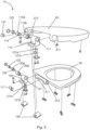
- 1 and figure 5 each show an exploded drawing of a 3D model of the hinge bearing device (10) with a cover (20) and a seat (30).
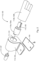
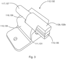
- the preferred embodiments shown show two identical bearing blocks (110, 130) with two identical damper elements (115, 135).
- These damper elements (115, 135) are each arranged with a structurally identical first and third axle component (112a, 132a) within the first and second axle mount (111, 131) of the first and second bearing block (111, 130).
- the first and third axle component (112a, 132a) are positively connected to the respective damper element (115, 135).
- the first and second damper elements (115, 135) each form a peg-like extension on the end face.
- the peg-like extension extends substantially coaxially along the first and/or second pivot axis with a substantially rectangular cross-section.
- the first and third axle components (112a, 132a) receive the peg-like extension of the first and second damper element (115, 135) in a form-fitting manner and form a peg transversely to the first and second pivot axis, limited by the outer diameter of the first and third axle component (112a, 132a). on their respective front side.
- These pins are designed for a positive connection with the first bearing mount of the cover (20) and the seat (30) in order to transfer the torque of the cover and seat resulting from the weight and/or actuating force to the first and second damper element (115, 135 ) transferred to.
- the cover and the seat are rotatably mounted about the first to fourth pivot axis relative to the first and second bearing block.
- the first axle mount (111) and the second axle mount (131) are also structurally identical.
- the first bearing block and the second bearing block (110, 130) hold the identical third and fourth axle bodies (117, 137) in a detachable manner by means of a screw or pin connection.
- the first and second damper elements (115, 135) form the first axle component and the third axle component as journals on the face side.
- the third axle body (117) and the fourth axle body (137), which is structurally identical, have on the front side on the respective first section a complementary pin for the first and second Damper element (115, times 135) or the first and third axle components formed groove which form a form-fitting connection in the assembled state at least in the tangential direction.
- the third and fourth axle bodies (117, 137) are connected to the first and second bearing blocks (110, 130) in a non-positive and positive manner by means of a screw and/or a pin, the first axle component of the first rotary damper and the third Axle component of the second rotary damper via the third and fourth axle body (117, 137) fixed in the first and second bearing block (110, 130) torque-proof with the first and second bearing block (110, 130) thus also connected to the pelvis (40).
- the second and fourth axle components (112b, 132b) are not fixed in the first and second bearing blocks (110, 130), respectively.
- first and second bearing block (110, 130) designed as a flange or flange-like.
- the respective flange includes a bore through which the first and second bearing block (110, 130) can be attached to the basin (40).
- an adhesive and/or sealing element (150) is arranged between the basin (40) and the first and second bearing block (110, 130), each of which also has holes for the screw connection provided.
- first and second bearing seats (311, 312) of the seat are located on the inside between the first and second bearing blocks (110, 130) and the first and second bearing seats (211, 212) of the cover are located on the outside outside of the first and second bearing block (110,130) arranged.
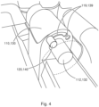
- the bearing block (110, 130) has a locking groove (119, 139) following a circular path on the front side with an adjoining locking point (119, 139) provided for the open position of the seat (30), in which a locking element (120 , 140) with a first end in a form-fitting manner in the radial direction and is movably arranged in the tangential direction, ie following the circular path.
- the locking element (120, 140) is arranged with a second end, shown schematically, in a form-fitting manner in the locking element receptacle.
- Fig. 7a-c show a particularly preferred further embodiment of a hinge bearing device (10), in which the second and fourth axle components (112b, 132b) have a locking recess (122).
- a locking device comprising a locking element (121a) and a spring element (121b) acts on the second and fourth axle component (112b, 132b) in the radial direction.
- Figure 7a shows the hinge bearing device in a closed position of the cover and/or seat, the cover and the seat have an opening angle of essentially 0° with respect to a horizontal plane.
- Figure 7c shows the hinge bearing device in an open position of the cover and/or seat, in which the locking element (121a) of the locking device engages in the locking recess (122) in the radial direction.
- the cover and the seat in this exemplary embodiment have an opening angle of approximately 100° with respect to a horizontal plane.
- the locking device or the enclosed spring element has the smallest deflection.
- FIG 7b The position shown shows the hinge bearing device in a position in which the spring element is substantially maximally deflected in an embodiment shown in relation to the open and closed position before the locking element snaps into the locking recess in the closed position.
- the locking element in order to lock the seat and cover in the open position or to release them, the locking element must slide over a radial elevation of the second and fourth axle components (112b, 132b).
- the radial elevation essentially follows a curved path.
- the required force for locking or releasing the cover (20) and the seat (30) into or out of the open position can be set via the course of the slope and the radial extension of the cam track on the one hand and the rigidity of the spring element (121b) on the other.
- a freewheel element (123) is arranged between the first or third axle component (112a, 132a) and the respective third or fourth axle body (117, 137).
- the freewheel element (123) is essentially positively connected to the first or third axle component (112a, 132a) and the respective third or fourth axle body (117, 137).
- the first and third axle components (112a, 132a) can be pivoted relative to the third or fourth axle body (117, 137) over a pivoting range defined by the freewheel.
- the freewheeling element (123) acts as a kind of rotation brake, which continuously brakes the pivoting movement between the open position and the maximum position of the cover (20) and the seat (30). This advantageously prevents overloading of the hinge bearing device, in particular of the first and second rotary dampers contained therein.
- Figure 8a shows the arrangement of the freewheel element (123) between the first or second axle body (112, 132) and the third or fourth axle body (117, 137) in the closed position of the cover (20) and the seat (30).
- Figure 8b shows this arrangement in a substantially maximum position of the cover (20) and the seat (30).
- FIG. 9 shows a basin (40) with a seat (30) and lid (20) mounted by means of a hinge bearing device (10).
- the lid (20) is locked in an open position and the seat (30) is placed essentially horizontally on top of the basin (40) in a closed position.
- the embodiment shown there shows an arrangement of the hinge bearing device (10) in a rear area, essentially in a rear half, on the upper side of the pelvis (40) on its essentially horizontally extending attachment surface (410).
- the seat (30) has a support space (314) in a rear lateral portion and a support surface (411) arranged on top of the pelvis (40) and oriented toward the seat.
- the support space (314) and the support surface (411) arranged therein offer users, in particular users with mobility impairments, of such a toilet, in particular for toilets arranged in moving vehicles, good support, for example when sitting down and standing up.
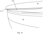
- FIG. 10 shows a basin (40) with a lid (20) in the closed position.
- the illustrated embodiment shows a lid (20) with a lid edge (214) on the underside of the lid (20) offset inward collar (215) to a lower Edge tilted outward contact of the user with the seat (30) and / or the pool (40) or the top of the pool (40) prevents.
Landscapes
- Health & Medical Sciences (AREA)
- Public Health (AREA)
- Pivots And Pivotal Connections (AREA)
- Toilet Supplies (AREA)
Applications Claiming Priority (1)
| Application Number | Priority Date | Filing Date | Title |
|---|---|---|---|
| DE202018105278.0U DE202018105278U1 (de) | 2018-09-14 | 2018-09-14 | Scharnierlagervorrichtung zur schwenkbaren Befestigung eines Deckels und/oder eines Sitzes an einem Becken einer Toilette |
Publications (2)
| Publication Number | Publication Date |
|---|---|
| EP3622868A1 EP3622868A1 (de) | 2020-03-18 |
| EP3622868B1 true EP3622868B1 (de) | 2023-07-12 |
Family
ID=67809293
Family Applications (1)
| Application Number | Title | Priority Date | Filing Date |
|---|---|---|---|
| EP19194306.7A Active EP3622868B1 (de) | 2018-09-14 | 2019-08-29 | Scharnierlagervorrichtung zur schwenkbaren befestigung eines deckels und/oder eines sitzes an einem becken einer toilette |
Country Status (5)
| Country | Link |
|---|---|
| EP (1) | EP3622868B1 (da) |
| DE (1) | DE202018105278U1 (da) |
| DK (1) | DK3622868T3 (da) |
| ES (1) | ES2959395T3 (da) |
| PL (1) | PL3622868T3 (da) |
Families Citing this family (2)
| Publication number | Priority date | Publication date | Assignee | Title |
|---|---|---|---|---|
| CN113069029A (zh) * | 2021-05-06 | 2021-07-06 | 宁波瑞联维保轨道交通设备有限公司 | 止动构件、便器盖、便器座用止动组件及一种移动车辆马桶用便器盖、便器座套件 |
| DE202021103619U1 (de) * | 2021-07-05 | 2021-07-15 | Trainvac GmbH | Vakuumtoilette |
Citations (2)
| Publication number | Priority date | Publication date | Assignee | Title |
|---|---|---|---|---|
| DE202010000453U1 (de) * | 2010-03-24 | 2010-06-02 | Eisl Sanitär Ges.m.b.H. | Toilettensitz |
| US20110296600A1 (en) * | 2010-06-07 | 2011-12-08 | Foremost Groups, Inc. | Toilet seat quick release system |
Family Cites Families (6)
| Publication number | Priority date | Publication date | Assignee | Title |
|---|---|---|---|---|
| DE102004041034B4 (de) | 2004-08-25 | 2006-08-10 | Pagette Sanitär Produktions- und Vertriebsgesellschaft mbH | WC-Sitz-Deckel-Kombination |
| FR2898033B1 (fr) * | 2006-03-02 | 2010-07-30 | Daniel Mauduit | Toilettes a palier et tourillon munis de moyens d'attraction magnetique |
| DE102007010930B4 (de) | 2007-03-05 | 2010-01-28 | Pagette Gmbh | Dämpfungseinrichtung |
| DE202009003907U1 (de) | 2009-03-23 | 2009-05-28 | Evac Gmbh | Arretierbare WC-Scharniervorrichtung |
| WO2013097204A1 (zh) * | 2011-12-31 | 2013-07-04 | Liu Zhifang | 马桶盖板组的快速自动拆装结构 |
| CN102764095B (zh) * | 2012-06-21 | 2014-10-08 | 彭东 | 一种马桶盖板与座体的连接锁固装置 |
-
2018
- 2018-09-14 DE DE202018105278.0U patent/DE202018105278U1/de not_active Expired - Lifetime
-
2019
- 2019-08-29 EP EP19194306.7A patent/EP3622868B1/de active Active
- 2019-08-29 PL PL19194306.7T patent/PL3622868T3/pl unknown
- 2019-08-29 ES ES19194306T patent/ES2959395T3/es active Active
- 2019-08-29 DK DK19194306.7T patent/DK3622868T3/da active
Patent Citations (2)
| Publication number | Priority date | Publication date | Assignee | Title |
|---|---|---|---|---|
| DE202010000453U1 (de) * | 2010-03-24 | 2010-06-02 | Eisl Sanitär Ges.m.b.H. | Toilettensitz |
| US20110296600A1 (en) * | 2010-06-07 | 2011-12-08 | Foremost Groups, Inc. | Toilet seat quick release system |
Also Published As
| Publication number | Publication date |
|---|---|
| ES2959395T3 (es) | 2024-02-26 |
| DE202018105278U1 (de) | 2019-12-17 |
| EP3622868A1 (de) | 2020-03-18 |
| PL3622868T3 (pl) | 2024-01-03 |
| DK3622868T3 (da) | 2023-09-18 |
Similar Documents
| Publication | Publication Date | Title |
|---|---|---|
| DE102009039461B4 (de) | Beschlag für einen Fahrzeugsitz | |
| EP3622868B1 (de) | Scharnierlagervorrichtung zur schwenkbaren befestigung eines deckels und/oder eines sitzes an einem becken einer toilette | |
| DE10329959A1 (de) | Halter für einen Getränkebehälter | |
| EP0999311A1 (de) | Schachtdeckel zum staubdichten Verschliessen eines Schachtes, insbesondere eines Brunnenschachtes | |
| DE102004010491B4 (de) | Beschlag für einen Fahrzeugsitz | |
| EP1068419B1 (de) | Mit einem türscharnier baulich vereinigter türfeststeller | |
| DE19734841A1 (de) | Mit einem aushängbaren Türscharnier baulich vereinigter Türfeststeller | |
| DE102012012852A9 (de) | Beschlag für einen Fahrzeugsitz sowie Fahrzeugsitz | |
| DE69709540T2 (de) | Toilettendeckelvorrichtung | |
| EP1073820B1 (de) | Kraftwagentürscharnier mit integrierter brems- und haltefunktion | |
| EP3236825A1 (de) | Wc-sitzgarnituranordnung | |
| EP3851004B1 (de) | Montageeinrichtung zur lösbaren montage eines garniturteils auf einem wc-körper | |
| DE3238889C2 (da) | ||
| EP3517009B1 (de) | Wc-deckelgarnitur mit mindestens einem befestigungselement und wc mit verriegelungseinrichtung | |
| DE102007010930B4 (de) | Dämpfungseinrichtung | |
| EP1167157A1 (de) | Zusammenklappbarer Kinderwagen mit verschwenkbaren Schwenkschiebern | |
| EP2465387A1 (de) | Gelenk, insbesondere Schwenkgelenk | |
| DE202018002362U1 (de) | WC-Garnitur und WC mit Verriegelungseinrichtung | |
| EP1728454B1 (de) | Einzelfederelement | |
| DE202024100216U1 (de) | Montageeinrichtung für WC-Garniturteil | |
| DE102010030018A1 (de) | Drehbeschlag mit integrierter Bremsvorrichtung | |
| AT502775B1 (de) | Scharnierbrücke | |
| DE102005049965B4 (de) | Toilettensitzanordnung | |
| DE102004011267B4 (de) | Neigungsverstellbeschlag für die Rückenlehne eines Kraftfahrzeugsitzes | |
| DE102004020394A1 (de) | Vorrichtung zur Erhöhung der Sitzhöhe auf einem Klosett |
Legal Events
| Date | Code | Title | Description |
|---|---|---|---|
| PUAI | Public reference made under article 153(3) epc to a published international application that has entered the european phase |
Free format text: ORIGINAL CODE: 0009012 |
|
| STAA | Information on the status of an ep patent application or granted ep patent |
Free format text: STATUS: THE APPLICATION HAS BEEN PUBLISHED |
|
| AK | Designated contracting states |
Kind code of ref document: A1 Designated state(s): AL AT BE BG CH CY CZ DE DK EE ES FI FR GB GR HR HU IE IS IT LI LT LU LV MC MK MT NL NO PL PT RO RS SE SI SK SM TR |
|
| AX | Request for extension of the european patent |
Extension state: BA ME |
|
| STAA | Information on the status of an ep patent application or granted ep patent |
Free format text: STATUS: REQUEST FOR EXAMINATION WAS MADE |
|
| 17P | Request for examination filed |
Effective date: 20200918 |
|
| RBV | Designated contracting states (corrected) |
Designated state(s): AL AT BE BG CH CY CZ DE DK EE ES FI FR GB GR HR HU IE IS IT LI LT LU LV MC MK MT NL NO PL PT RO RS SE SI SK SM TR |
|
| RAP1 | Party data changed (applicant data changed or rights of an application transferred) |
Owner name: EVAC GMBH |
|
| STAA | Information on the status of an ep patent application or granted ep patent |
Free format text: STATUS: EXAMINATION IS IN PROGRESS |
|
| 17Q | First examination report despatched |
Effective date: 20220602 |
|
| GRAP | Despatch of communication of intention to grant a patent |
Free format text: ORIGINAL CODE: EPIDOSNIGR1 |
|
| STAA | Information on the status of an ep patent application or granted ep patent |
Free format text: STATUS: GRANT OF PATENT IS INTENDED |
|
| INTG | Intention to grant announced |
Effective date: 20221215 |
|
| GRAJ | Information related to disapproval of communication of intention to grant by the applicant or resumption of examination proceedings by the epo deleted |
Free format text: ORIGINAL CODE: EPIDOSDIGR1 |
|
| STAA | Information on the status of an ep patent application or granted ep patent |
Free format text: STATUS: EXAMINATION IS IN PROGRESS |
|
| GRAP | Despatch of communication of intention to grant a patent |
Free format text: ORIGINAL CODE: EPIDOSNIGR1 |
|
| STAA | Information on the status of an ep patent application or granted ep patent |
Free format text: STATUS: GRANT OF PATENT IS INTENDED |
|
| INTC | Intention to grant announced (deleted) | ||
| INTG | Intention to grant announced |
Effective date: 20230504 |
|
| GRAS | Grant fee paid |
Free format text: ORIGINAL CODE: EPIDOSNIGR3 |
|
| GRAA | (expected) grant |
Free format text: ORIGINAL CODE: 0009210 |
|
| STAA | Information on the status of an ep patent application or granted ep patent |
Free format text: STATUS: THE PATENT HAS BEEN GRANTED |
|
| AK | Designated contracting states |
Kind code of ref document: B1 Designated state(s): AL AT BE BG CH CY CZ DE DK EE ES FI FR GB GR HR HU IE IS IT LI LT LU LV MC MK MT NL NO PL PT RO RS SE SI SK SM TR |
|
| REG | Reference to a national code |
Ref country code: CH Ref legal event code: EP |
|
| REG | Reference to a national code |
Ref country code: IE Ref legal event code: FG4D Free format text: LANGUAGE OF EP DOCUMENT: GERMAN |
|
| REG | Reference to a national code |
Ref country code: DE Ref legal event code: R096 Ref document number: 502019008468 Country of ref document: DE |
|
| REG | Reference to a national code |
Ref country code: DK Ref legal event code: T3 Effective date: 20230913 |
|
| REG | Reference to a national code |
Ref country code: LT Ref legal event code: MG9D |
|
| P01 | Opt-out of the competence of the unified patent court (upc) registered |
Effective date: 20231005 |
|
| REG | Reference to a national code |
Ref country code: NL Ref legal event code: MP Effective date: 20230712 |
|
| PG25 | Lapsed in a contracting state [announced via postgrant information from national office to epo] |
Ref country code: NL Free format text: LAPSE BECAUSE OF FAILURE TO SUBMIT A TRANSLATION OF THE DESCRIPTION OR TO PAY THE FEE WITHIN THE PRESCRIBED TIME-LIMIT Effective date: 20230712 |
|
| PG25 | Lapsed in a contracting state [announced via postgrant information from national office to epo] |
Ref country code: GR Free format text: LAPSE BECAUSE OF FAILURE TO SUBMIT A TRANSLATION OF THE DESCRIPTION OR TO PAY THE FEE WITHIN THE PRESCRIBED TIME-LIMIT Effective date: 20231013 |
|
| PG25 | Lapsed in a contracting state [announced via postgrant information from national office to epo] |
Ref country code: IS Free format text: LAPSE BECAUSE OF FAILURE TO SUBMIT A TRANSLATION OF THE DESCRIPTION OR TO PAY THE FEE WITHIN THE PRESCRIBED TIME-LIMIT Effective date: 20231112 |
|
| PG25 | Lapsed in a contracting state [announced via postgrant information from national office to epo] |
Ref country code: SE Free format text: LAPSE BECAUSE OF FAILURE TO SUBMIT A TRANSLATION OF THE DESCRIPTION OR TO PAY THE FEE WITHIN THE PRESCRIBED TIME-LIMIT Effective date: 20230712 Ref country code: RS Free format text: LAPSE BECAUSE OF FAILURE TO SUBMIT A TRANSLATION OF THE DESCRIPTION OR TO PAY THE FEE WITHIN THE PRESCRIBED TIME-LIMIT Effective date: 20230712 Ref country code: PT Free format text: LAPSE BECAUSE OF FAILURE TO SUBMIT A TRANSLATION OF THE DESCRIPTION OR TO PAY THE FEE WITHIN THE PRESCRIBED TIME-LIMIT Effective date: 20231113 Ref country code: NO Free format text: LAPSE BECAUSE OF FAILURE TO SUBMIT A TRANSLATION OF THE DESCRIPTION OR TO PAY THE FEE WITHIN THE PRESCRIBED TIME-LIMIT Effective date: 20231012 Ref country code: LV Free format text: LAPSE BECAUSE OF FAILURE TO SUBMIT A TRANSLATION OF THE DESCRIPTION OR TO PAY THE FEE WITHIN THE PRESCRIBED TIME-LIMIT Effective date: 20230712 Ref country code: LT Free format text: LAPSE BECAUSE OF FAILURE TO SUBMIT A TRANSLATION OF THE DESCRIPTION OR TO PAY THE FEE WITHIN THE PRESCRIBED TIME-LIMIT Effective date: 20230712 Ref country code: IS Free format text: LAPSE BECAUSE OF FAILURE TO SUBMIT A TRANSLATION OF THE DESCRIPTION OR TO PAY THE FEE WITHIN THE PRESCRIBED TIME-LIMIT Effective date: 20231112 Ref country code: HR Free format text: LAPSE BECAUSE OF FAILURE TO SUBMIT A TRANSLATION OF THE DESCRIPTION OR TO PAY THE FEE WITHIN THE PRESCRIBED TIME-LIMIT Effective date: 20230712 Ref country code: GR Free format text: LAPSE BECAUSE OF FAILURE TO SUBMIT A TRANSLATION OF THE DESCRIPTION OR TO PAY THE FEE WITHIN THE PRESCRIBED TIME-LIMIT Effective date: 20231013 Ref country code: FI Free format text: LAPSE BECAUSE OF FAILURE TO SUBMIT A TRANSLATION OF THE DESCRIPTION OR TO PAY THE FEE WITHIN THE PRESCRIBED TIME-LIMIT Effective date: 20230712 |
|
| REG | Reference to a national code |
Ref country code: ES Ref legal event code: FG2A Ref document number: 2959395 Country of ref document: ES Kind code of ref document: T3 Effective date: 20240226 |
|
| REG | Reference to a national code |
Ref country code: DE Ref legal event code: R097 Ref document number: 502019008468 Country of ref document: DE |
|
| PG25 | Lapsed in a contracting state [announced via postgrant information from national office to epo] |
Ref country code: LU Free format text: LAPSE BECAUSE OF NON-PAYMENT OF DUE FEES Effective date: 20230829 |
|
| PG25 | Lapsed in a contracting state [announced via postgrant information from national office to epo] |
Ref country code: SM Free format text: LAPSE BECAUSE OF FAILURE TO SUBMIT A TRANSLATION OF THE DESCRIPTION OR TO PAY THE FEE WITHIN THE PRESCRIBED TIME-LIMIT Effective date: 20230712 Ref country code: RO Free format text: LAPSE BECAUSE OF FAILURE TO SUBMIT A TRANSLATION OF THE DESCRIPTION OR TO PAY THE FEE WITHIN THE PRESCRIBED TIME-LIMIT Effective date: 20230712 Ref country code: LU Free format text: LAPSE BECAUSE OF NON-PAYMENT OF DUE FEES Effective date: 20230829 Ref country code: EE Free format text: LAPSE BECAUSE OF FAILURE TO SUBMIT A TRANSLATION OF THE DESCRIPTION OR TO PAY THE FEE WITHIN THE PRESCRIBED TIME-LIMIT Effective date: 20230712 Ref country code: CZ Free format text: LAPSE BECAUSE OF FAILURE TO SUBMIT A TRANSLATION OF THE DESCRIPTION OR TO PAY THE FEE WITHIN THE PRESCRIBED TIME-LIMIT Effective date: 20230712 Ref country code: SK Free format text: LAPSE BECAUSE OF FAILURE TO SUBMIT A TRANSLATION OF THE DESCRIPTION OR TO PAY THE FEE WITHIN THE PRESCRIBED TIME-LIMIT Effective date: 20230712 Ref country code: MC Free format text: LAPSE BECAUSE OF FAILURE TO SUBMIT A TRANSLATION OF THE DESCRIPTION OR TO PAY THE FEE WITHIN THE PRESCRIBED TIME-LIMIT Effective date: 20230712 |
|
| REG | Reference to a national code |
Ref country code: BE Ref legal event code: MM Effective date: 20230831 |
|
| PLBE | No opposition filed within time limit |
Free format text: ORIGINAL CODE: 0009261 |
|
| STAA | Information on the status of an ep patent application or granted ep patent |
Free format text: STATUS: NO OPPOSITION FILED WITHIN TIME LIMIT |
|
| REG | Reference to a national code |
Ref country code: IE Ref legal event code: MM4A |
|
| 26N | No opposition filed |
Effective date: 20240415 |
|
| PG25 | Lapsed in a contracting state [announced via postgrant information from national office to epo] |
Ref country code: IE Free format text: LAPSE BECAUSE OF NON-PAYMENT OF DUE FEES Effective date: 20230829 |
|
| PG25 | Lapsed in a contracting state [announced via postgrant information from national office to epo] |
Ref country code: IE Free format text: LAPSE BECAUSE OF NON-PAYMENT OF DUE FEES Effective date: 20230829 Ref country code: SI Free format text: LAPSE BECAUSE OF FAILURE TO SUBMIT A TRANSLATION OF THE DESCRIPTION OR TO PAY THE FEE WITHIN THE PRESCRIBED TIME-LIMIT Effective date: 20230712 |
|
| PG25 | Lapsed in a contracting state [announced via postgrant information from national office to epo] |
Ref country code: BE Free format text: LAPSE BECAUSE OF NON-PAYMENT OF DUE FEES Effective date: 20230831 |
|
| PG25 | Lapsed in a contracting state [announced via postgrant information from national office to epo] |
Ref country code: BG Free format text: LAPSE BECAUSE OF FAILURE TO SUBMIT A TRANSLATION OF THE DESCRIPTION OR TO PAY THE FEE WITHIN THE PRESCRIBED TIME-LIMIT Effective date: 20230712 |
|
| PG25 | Lapsed in a contracting state [announced via postgrant information from national office to epo] |
Ref country code: BG Free format text: LAPSE BECAUSE OF FAILURE TO SUBMIT A TRANSLATION OF THE DESCRIPTION OR TO PAY THE FEE WITHIN THE PRESCRIBED TIME-LIMIT Effective date: 20230712 |
|
| PG25 | Lapsed in a contracting state [announced via postgrant information from national office to epo] |
Ref country code: CY Free format text: LAPSE BECAUSE OF FAILURE TO SUBMIT A TRANSLATION OF THE DESCRIPTION OR TO PAY THE FEE WITHIN THE PRESCRIBED TIME-LIMIT; INVALID AB INITIO Effective date: 20190829 |
|
| PG25 | Lapsed in a contracting state [announced via postgrant information from national office to epo] |
Ref country code: HU Free format text: LAPSE BECAUSE OF FAILURE TO SUBMIT A TRANSLATION OF THE DESCRIPTION OR TO PAY THE FEE WITHIN THE PRESCRIBED TIME-LIMIT; INVALID AB INITIO Effective date: 20190829 |
|
| PGFP | Annual fee paid to national office [announced via postgrant information from national office to epo] |
Ref country code: ES Payment date: 20250909 Year of fee payment: 7 |
|
| PGFP | Annual fee paid to national office [announced via postgrant information from national office to epo] |
Ref country code: DK Payment date: 20250825 Year of fee payment: 7 Ref country code: DE Payment date: 20250827 Year of fee payment: 7 |
|
| PGFP | Annual fee paid to national office [announced via postgrant information from national office to epo] |
Ref country code: PL Payment date: 20250807 Year of fee payment: 7 Ref country code: IT Payment date: 20250821 Year of fee payment: 7 |
|
| PGFP | Annual fee paid to national office [announced via postgrant information from national office to epo] |
Ref country code: GB Payment date: 20250826 Year of fee payment: 7 |
|
| PGFP | Annual fee paid to national office [announced via postgrant information from national office to epo] |
Ref country code: FR Payment date: 20250819 Year of fee payment: 7 Ref country code: AT Payment date: 20250819 Year of fee payment: 7 |
|
| PGFP | Annual fee paid to national office [announced via postgrant information from national office to epo] |
Ref country code: CH Payment date: 20250901 Year of fee payment: 7 |
|
| PG25 | Lapsed in a contracting state [announced via postgrant information from national office to epo] |
Ref country code: TR Free format text: LAPSE BECAUSE OF FAILURE TO SUBMIT A TRANSLATION OF THE DESCRIPTION OR TO PAY THE FEE WITHIN THE PRESCRIBED TIME-LIMIT Effective date: 20230712 |