EP3620574B1 - Wulstring und verfahren zur herstellung davon - Google Patents
Wulstring und verfahren zur herstellung davon Download PDFInfo
- Publication number
- EP3620574B1 EP3620574B1 EP18794322.0A EP18794322A EP3620574B1 EP 3620574 B1 EP3620574 B1 EP 3620574B1 EP 18794322 A EP18794322 A EP 18794322A EP 3620574 B1 EP3620574 B1 EP 3620574B1
- Authority
- EP
- European Patent Office
- Prior art keywords
- wire
- bead
- diameter
- bead wire
- mpa
- Prior art date
- Legal status (The legal status is an assumption and is not a legal conclusion. Google has not performed a legal analysis and makes no representation as to the accuracy of the status listed.)
- Active
Links
Images

Classifications
-
- B—PERFORMING OPERATIONS; TRANSPORTING
- B60—VEHICLES IN GENERAL
- B60C—VEHICLE TYRES; TYRE INFLATION; TYRE CHANGING; CONNECTING VALVES TO INFLATABLE ELASTIC BODIES IN GENERAL; DEVICES OR ARRANGEMENTS RELATED TO TYRES
- B60C15/00—Tyre beads, e.g. ply turn-up or overlap
- B60C15/04—Bead cores
-
- B—PERFORMING OPERATIONS; TRANSPORTING
- B29—WORKING OF PLASTICS; WORKING OF SUBSTANCES IN A PLASTIC STATE IN GENERAL
- B29D—PRODUCING PARTICULAR ARTICLES FROM PLASTICS OR FROM SUBSTANCES IN A PLASTIC STATE
- B29D30/00—Producing pneumatic or solid tyres or parts thereof
- B29D30/06—Pneumatic tyres or parts thereof (e.g. produced by casting, moulding, compression moulding, injection moulding, centrifugal casting)
- B29D30/48—Bead-rings or bead-cores; Treatment thereof prior to building the tyre
-
- B—PERFORMING OPERATIONS; TRANSPORTING
- B21—MECHANICAL METAL-WORKING WITHOUT ESSENTIALLY REMOVING MATERIAL; PUNCHING METAL
- B21C—MANUFACTURE OF METAL SHEETS, WIRE, RODS, TUBES, PROFILES OR LIKE SEMI-MANUFACTURED PRODUCTS OTHERWISE THAN BY ROLLING; AUXILIARY OPERATIONS USED IN CONNECTION WITH METAL-WORKING WITHOUT ESSENTIALLY REMOVING MATERIAL
- B21C1/00—Manufacture of metal sheets, wire, rods, tubes or like semi-manufactured products by drawing
- B21C1/02—Drawing metal wire or like flexible metallic material by drawing machines or apparatus in which the drawing action is effected by drums
-
- D—TEXTILES; PAPER
- D07—ROPES; CABLES OTHER THAN ELECTRIC
- D07B—ROPES OR CABLES IN GENERAL
- D07B1/00—Constructional features of ropes or cables
- D07B1/06—Ropes or cables built-up from metal wires, e.g. of section wires around a hemp core
-
- B—PERFORMING OPERATIONS; TRANSPORTING
- B29—WORKING OF PLASTICS; WORKING OF SUBSTANCES IN A PLASTIC STATE IN GENERAL
- B29D—PRODUCING PARTICULAR ARTICLES FROM PLASTICS OR FROM SUBSTANCES IN A PLASTIC STATE
- B29D30/00—Producing pneumatic or solid tyres or parts thereof
- B29D30/06—Pneumatic tyres or parts thereof (e.g. produced by casting, moulding, compression moulding, injection moulding, centrifugal casting)
- B29D30/48—Bead-rings or bead-cores; Treatment thereof prior to building the tyre
- B29D2030/485—Bead-rings or bead-cores; Treatment thereof prior to building the tyre the bead cores being made using a band containing a plurality of wires embedded in rubber
-
- B—PERFORMING OPERATIONS; TRANSPORTING
- B60—VEHICLES IN GENERAL
- B60C—VEHICLE TYRES; TYRE INFLATION; TYRE CHANGING; CONNECTING VALVES TO INFLATABLE ELASTIC BODIES IN GENERAL; DEVICES OR ARRANGEMENTS RELATED TO TYRES
- B60C15/00—Tyre beads, e.g. ply turn-up or overlap
- B60C15/04—Bead cores
- B60C2015/046—Cable cores, i.e. cores made-up of twisted wires
-
- D—TEXTILES; PAPER
- D07—ROPES; CABLES OTHER THAN ELECTRIC
- D07B—ROPES OR CABLES IN GENERAL
- D07B2501/00—Application field
- D07B2501/20—Application field related to ropes or cables
- D07B2501/2046—Tyre cords
- D07B2501/2053—Tyre cords for wheel rim attachment
Definitions
- the present invention relates to a bead ring formed from a bead wire that has been subjected to wire drawing and a method for producing the same. More specifically, the present invention relates to a bead ring that can improve processability during forming while reducing production costs by setting the true strain, tensile strength, and proof stress of the bead wire that constitutes the bead ring to specific ranges.
- a bead ring is formed using a bead wire that has been subjected to wire drawing.
- a bead wire before processing is drawn up to a predetermined wire diameter
- the bead wire after wire drawing is subjected to a heat treatment
- the bead wire is further drawn to the wire diameter of the final shape. That is, a general bead wire is subjected to wire drawing twice to reach the final shape.
- the heat treatment after wire drawing is a step of removing strain generated in the wire by wire drawing.
- An object of the present invention is to provide a bead ring that can improve processability during forming while reducing production costs by setting the true strain, tensile strength, and proof stress of the bead wire that constitutes the bead ring to specific ranges, and a method for producing the same.
- the inventors of the present invention have obtained the following finding: in order to improve processability during forming of a bead ring formed from a bead wire that has been subjected to wire drawing without undergoing a heat treatment, it is important to set particularly the proof stress of the bead wire to a specific range; and thus have completed the present invention.
- the bead wire has a true strain ⁇ of 2.80 or greater as calculated by Equation (1) above, a tensile strength of 2000 MPa or greater, and a proof stress of 1700 MPa to 1980 MPa, thus allowing improvement of processability during forming. Additionally, in an embodiment of the present invention, the bead wire has a true strain ⁇ of 2.80 or greater, and does not undergo a heat treatment, and thus keeps the production cost of the bead wire relatively inexpensive, as compared to a bead wire of the related art. This allows reduction of the production cost of the bead ring.
- the bead wire is subjected to wire drawing so as to have a true strain ⁇ of 2.80 or greater as calculated by Equation (1) above. This allows improvement of processability during forming by processing the bead wire having a tensile strength of 2000 MPa or greater and a proof stress of 1700 MPa to 1980 MPa, and winding the bead wire to form an annular bead ring.
- the wire residual rotation of the bead wire is preferably 0 ⁇ 0.25 times/6 m in the longitudinal direction. This allows effective improvement of processability during forming.
- the tensile strength of the bead wire is preferably 2200 MPa or less. This allows effective improvement of processability during forming.
- proof stress refers to the value of the stress at the intersection point between a straight line and a curved line, when the straight line is drawn in parallel to the elasticity elongation portion from the point of strain 0.2% in a stress-strain curve obtained in the tensile test.
- the wire residual rotation is obtained by withdrawing 6 m of a bead wire from a bobbin around which the bead wire is wound, and measuring the amount of rotation [times/6 m] at the tip of the bead wire in a withdrawn state.
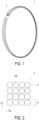
- FIG. 1 and FIG. 2 illustrate a bead ring according to an embodiment of the present invention.
- a bead ring 1 is composed of one or a plurality of bead wires 2 wound in a tire circumferential direction.
- a plurality of winding portions 2A of the bead wire 2 are arranged in a plurality of rows in a tire lateral direction Tw, and are stacked in a plurality of stages in a tire radial direction Tr to form a plurality of layers.
- the structure has four rows of the winding portions 2A both in the tire lateral direction Tw and the tire radial direction Tr, but the structure is not limited to that illustrated in FIG. 2 , and a structure having any number of rows and stages of the winding portions 2A may be employed.
- the bead ring 1 is formed from a bead wire 2 that has been subjected to wire drawing without undergoing a heat treatment.
- the material of the bead wire 2 is not particularly limited, but is preferably, for example, a steel cord.
- the wire diameter d 0 of the bead wire 2 before wire drawing is preferably from 5.0 mm to 5.5 mm
- the wire diameter d 1 of the bead wire 2 after wire drawing is preferably from 1.15 mm to 1.35 mm.
- the bead wire 2 may be wound, for example, after being coated with an unvulcanized rubber.
- the true strain ⁇ of the bead wire 2 which is a constituent member thereof, is 2.80 or greater.
- Truste strain ⁇ refers to a residual strain generated in the wire by wire drawing applied to the bead wire in the bead wire producing process.
- the true strain ⁇ is calculated by the following Equation (1), and is an indicator for evaluating the degree of wire drawing. For example, when the wire diameter d 0 of the bead wire 2 before wire drawing is 5.5 mm and the wire diameter d 1 of the bead wire 2 after wire drawing is 1.2 mm, the true strain ⁇ is 3.04.
- the bead wire when a bead wire is subjected to wire drawing twice as in the related art, the bead wire is generally drawn until the wire diameter reaches approximately 2/3 to 1/2 the initial wire diameter by the first wire drawing.
- the true strain ⁇ is 1.83 and deviates greatly from the range of the true strain ⁇ specified in an embodiment of the present invention.
- the bead wire 2 used in an embodiment of the present invention has been subjected to wire drawing without undergoing a heat treatment, and thus is configured so that the true strain ⁇ is higher than that of the bead wire in the related art.
- ⁇ ln d 0 / d 1 2
- the proof strain of the bead wire 2 is 1700 MPa to 1980 MPa.
- the proof strain of the bead wire 2 corresponds to the stress ⁇ 1 at the intersection point between the straight line L and the curved line M when the straight line L is drawn in parallel to the elasticity elongation portion from the point of strain 0.2% in the stress-strain curve illustrated in FIG. 4 , and is especially an indicator for evaluating processability during forming.
- the tensile strength of the bead wire 2 is 2000 MPa or greater.
- the tensile strength of the bead wire 2 corresponds to the stress ⁇ 2 , which is the maximum value of the curved line M in the stress-strain curve illustrated in FIG. 4 .
- the bead wire 2 which is a constituent member thereof, has a true strain ⁇ of 2.80 or greater as calculated by Equation (1) above, a tensile strength of 2000 MPa or greater, and a proof stress of 1700 MPa to 1980 MPa, thus allowing improvement of processability during forming.
- the bead wire 2 used in an embodiment of the present invention does not undergo a heat treatment, and thus keeps the production cost of the bead wire relatively inexpensive compared to the bead wires in the related art. This allows reduction of the production cost for the bead ring 2.
- the processability during forming deteriorates when the proof stress of the bead wire 2 is less than 1700 MPa or greater than 1980 MPa.
- FIG. 3 illustrates the bead rings 1 disposed coaxially, the bead rings 1 being in both the states in which the terminals of the bead wire 2 are fixed and unfixed.
- a bead ring 10 is the state in which the terminal of the bead wire 2 is fixed
- a bead ring 11 is a state in which the terminal of the bead wire 2 is unfixed.
- the bead ring 10 has a predetermined diameter after the bead forming, and the bead ring 11 is formed by peeling off approximately one round of the bead wire 2 wound in the circumferential direction of the bead ring 10.
- the diameter of the bead ring 1 with the terminal of the bead wire 2 fixed is D 0
- the diameter of the bead ring 1 with the terminal of the bead wire 2 unfixed is D 1
- the diameter D 1 is made smaller than the diameter D 0
- the reforming rate E of the bead wire 2 as calculated by Equation (2) below is preferably from 85% to 100%, and more preferably has an upper limit of less than 100%.
- the wire residual rotation of the bead wire 2 is preferably 0 ⁇ 0.25 times/6 m in the longitudinal direction.
- the appropriate setting of the residual rotation of the bead wire 2 in this manner allows effective improvement of processability during forming.
- the wire residual rotation may fall outside the range described above, and processability during forming tends to deteriorate.
- the tensile strength of the bead wire 2 is preferably 2200 MPa or less.
- the appropriate setting of the tensile strength of the bead wire 2 in this manner allows effective improvement of processability during forming.
- the tensile strength of the bead wire 2 is greater than 2200 MPa, the bead wire 2 is embrittled and can be easily broken.
- the bead wire 2 is subjected to wire drawing so as to have a true strain ⁇ of 2.80 or greater as calculated by Equation (1) below.
- the bead wire is drawn from the initial wire diameter to the wire diameter of the final shape by wire drawing, and is not subjected to a heat treatment in the wire drawing through which the wire diameter d 0 of the bead wire 2 before wire drawing reaches the wire diameter d 1 of the bead wire 2 after wire drawing.
- ⁇ ln d 0 / d 1 2
- the bead wire 2 is processed so as to have a tensile strength of 2000 MPa or greater and a proof stress of 1700 MPa to 1980 MPa, and then the bead wire 2 is wound to form an annular bead ring 1.
- the bead wire 2 is passed through a corrective roller so as to alleviate the structural orientation in the bead wire 2. This allows reduction of the proof stress of the bead wire 2.
- the bead wire 2 is subjected to wire drawing so as to have a true strain ⁇ of 2.80 or greater as calculated by Equation (1) above, thereby processing the bead wire 2 having a tensile strength of 2000 MPa or greater, a proof strain of 1700 MPa to 1980 MPa, and winding the bead wire 2 to form an annular bead ring 1, thus allowing improvement of processability during forming.
- the bead wire 2 used in an embodiment of the present invention does not undergo a heat treatment, and thus keeps the production cost of the bead wire relatively inexpensive in comparison with the bead wires in the related art. As a result, the production cost of the bead ring 2 can be reduced.
- the proof stress of the bead wire 2 is less than 1700 MPa or greater than 1980 MPa, processability during forming will deteriorate.
- the bead ring 1 produced by the producing method described above may also be used as a bead core of a pneumatic tire.
- bead rings formed from a bead wire that has been subjected to wire drawing bead rings of Examples 1 to 3 were made, in which the wire diameter d 0 of the bead wire before wire drawing [mm], wire diameter d 1 of the bead wire after wire drawing [mm], the true strain ⁇ (In(d 0 /d 1 ) 2 ), tensile strength [MPa], proof stress [MPa], reforming rate of bead wire [%], and wire residual rotation [times/6 m] were set as in Table 1.
- Examples 1 to 3 a structure composed of a bead wire subjected to wire drawing without undergoing a heat treatment was employed.
- the examples 1 and 3 belong to the scope of the present invention.
- a bead ring of a conventional example was prepared, which is formed from a bead wire that had been subjected to wire drawing twice, and underwent a heat treatment between the first and second wire drawing steps.
- the initial wire diameter of the bead wire was 5.5 mm
- the wire diameter d 0 of the bead wire before the second wire drawing was 2.0 mm
- the wire diameter d 1 of the bead wire after the second wire drawing was 1.2 mm.
- bead rings of Comparative Examples 1 and 2 were prepared using the same structure as in Example 1, except that the proof stress and the wire residual rotation [times/6 m] were changed.
- the production cost of the bead rings was evaluated. In the evaluation result, the case where the production cost was relatively low was rated “Good”, the case where the production cost was relatively high was rated “Acceptable”, and the case where the production cost was extremely high was rated “Fail”.
- the productivity in the bead forming of the bead rings was evaluated.
- the case where the productivity was high was rated "Excellent”
- the case where the productivity was relatively high was rated “Good”
- the case where the productivity was low was rated "Fail”.
- the bead rings of Examples 1 to 3 exhibited reduced production costs and improved forming productivity as compared to the conventional example by setting the true strain, tensile strength, and proof stress of the bead wires to specific ranges.
- Comparative Example 1 since the proof stress and reforming rate of the bead wire were set to be relatively high, the terminal of the bead ring was curled, which resulted in deterioration of forming productivity.
- Comparative Example 2 since the proof stress and reforming rate of the bead wire were set to be relatively low, the inner terminal of the bead ring was curled, which resulted in deterioration of forming productivity.
- Example 2 since the wire residual rotation was set to be high, there was a risk of deforming.
- Example 3 since the tensile strength was set to be high, there was a risk of wire breakage.
Landscapes
- Engineering & Computer Science (AREA)
- Mechanical Engineering (AREA)
- Tyre Moulding (AREA)
- Ropes Or Cables (AREA)
- Tires In General (AREA)
Claims (8)
- Ringförmiger Wulstring (1), der aus einem Reifenwulstdraht (2) ausgebildet ist, der einem Drahtziehen unterzogen wurde, wobei der Reifenwulstdraht (2) eine echte Beanspruchung ε von 2,80 oder mehr, wie durch Gleichung (1) berechnet, und eine Zugfestigkeit von 2000 MPa oder mehr aufweist;
 wobei d0: Drahtdurchmesser des Reifenwulstdrahts (2) vor dem Drahtziehen [mm], undd1: Drahtdurchmesser des Reifenwulstdrahts (2) nach dem Drahtziehen [mm],dadurch gekennzeichnet, dassder Reifenwulstdraht (2) eine Dehngrenze von 1700 MPa bis 1980 MPa aufweist, undeine Drahtrestdrehung des Reifenwulstdrahts (2) 0 ± 0,25-mal/6 m in der Längsrichtung beträgt.
 - Wulstring gemäß Anspruch 1, wobeieine Nachformungsrate E des Reifenwulstdrahts (2) von 85 % bis 100 % beträgt, berechnet durch Gleichung (2);
 wobeiD0: Durchmesser des Wulstrings (1) mit einer Endstelle des Reifenwulstdrahts (2) fixiert [mm], undD1: Durchmesser des Wulstrings (1) mit der Endstelle des Reifenwulstdrahts (2) unfixiert [mm].
 - Wulstring nach Anspruch 1 oder 2, wobei
die Zugfestigkeit des Reifenwulstdrahts (2) 2200 MPa oder weniger beträgt. - Wulstring gemäß Anspruch 1, wobeidie Zugfestigkeit des Reifenwulstdrahts (2) 2200 MPa oder weniger beträgt;der Drahtdurchmesser d1 des Reifenwulstdrahts (2) nach dem Drahtziehen von 1,15 mm bis 1,35 mm beträgt;eine Nachformungsrate E des Reifenwulstdrahts (2) wie berechnet durch E = D1/D0 x 100 % von 85 % bis 100 % beträgt, wobeiD0 ein Durchmesser (mm) des Wulstrings (1) mit einer Endstelle des Reifenwulstdrahts (2) fixiert ist, undD1 ein Durchmesser (mm) des Wulstrings (1) mit der Endstelle des Reifenwulstdrahts (2) unfixiert ist.
- Verfahren zum Herstellen eines Wulstrings (1), umfassendUnterziehen eines Reifenwulstdrahts (2) dem Drahtziehen, um eine echte Beanspruchung ε von 2,80 oder mehr aufzuweisen, wie durch Gleichung (1) berechnet, wobei dadurch ein Reifenwulstdraht (2) verarbeitet wird, der eine Zugfestigkeit von 2000 MPa oder mehr aufweist, und der Reifenwulstdraht (2) aufgewickelt wird, um einen ringförmigen Wulstring (1) auszubilden;
 wobeid0: Drahtdurchmesser des Reifenwulstdrahts (2) vor dem Drahtziehen [mm], undd1: Drahtdurchmesser des Reifenwulstdrahts (2) nach Drahtziehen [mm],dadurch gekennzeichnet, dassder Reifenwulstdraht (2) eine Dehngrenze von 1700 MPa bis 1980 MPa aufweist, undeine Drahtrestdrehung des Reifenwulstdrahts (2) 0 ± 0,25-mal/6 m in der Längsrichtung beträgt.
 - Verfahren zum Herstellen eines Wulstrings gemäß Anspruch 5, wobeieine Nachformungsrate E des Reifenwulstdrahts (2) von 85 % bis 100 % beträgt, berechnet durch Gleichung (2);
 wobeiD0: Durchmesser des Wulstrings (1) mit einer Endstelle des Reifenwulstdrahts (2) fixiert [mm], undD1: Durchmesser des Wulstrings (1) mit der Endstelle des Reifenwulstdrahts (2) unfixiert [mm].
 - Verfahren zum Herstellen eines Wulstrings gemäß Anspruch 5 oder 6, wobei
die Zugfestigkeit des Reifenwulstdrahts (2) 2200 MPa oder weniger beträgt. - Verfahren zum Herstellen eines Wulstrings gemäß Anspruch 5, wobeidie Zugfestigkeit des Reifenwulstdrahts (2) 2200 MPa oder weniger beträgt;der Drahtdurchmesser d1 des Reifenwulstdrahts (2) nach dem Drahtziehen von 1,15 mm bis 1,35 mm beträgt;eine Nachformungsrate E des Reifenwulstdrahts (2) wie berechnet durch E = D1/D0 x 100 % von 85 % bis 100 % beträgt, wobeiD0 ein Durchmesser (mm) des Wulstrings (1) mit einer Endstelle des Reifenwulstdrahts (2) fixiert ist, undD1 ein Durchmesser (mm) des Wulstrings (1) mit der Endstelle des Reifenwulstdrahts (2) unfixiert ist.
Applications Claiming Priority (2)
| Application Number | Priority Date | Filing Date | Title |
|---|---|---|---|
| JP2017091798A JP6520985B2 (ja) | 2017-05-02 | 2017-05-02 | ビードリング及びその製造方法 |
| PCT/JP2018/016799 WO2018203504A1 (ja) | 2017-05-02 | 2018-04-25 | ビードリング及びその製造方法 |
Publications (3)
| Publication Number | Publication Date |
|---|---|
| EP3620574A1 EP3620574A1 (de) | 2020-03-11 |
| EP3620574A4 EP3620574A4 (de) | 2021-02-24 |
| EP3620574B1 true EP3620574B1 (de) | 2023-08-16 |
Family
ID=64016101
Family Applications (1)
| Application Number | Title | Priority Date | Filing Date |
|---|---|---|---|
| EP18794322.0A Active EP3620574B1 (de) | 2017-05-02 | 2018-04-25 | Wulstring und verfahren zur herstellung davon |
Country Status (5)
| Country | Link |
|---|---|
| US (1) | US20200062045A1 (de) |
| EP (1) | EP3620574B1 (de) |
| JP (1) | JP6520985B2 (de) |
| CN (1) | CN110603358A (de) |
| WO (1) | WO2018203504A1 (de) |
Families Citing this family (1)
| Publication number | Priority date | Publication date | Assignee | Title |
|---|---|---|---|---|
| EP4370741A1 (de) * | 2021-07-13 | 2024-05-22 | NV Bekaert SA | Stahlseil zur verstärkung von gummi |
Family Cites Families (16)
| Publication number | Priority date | Publication date | Assignee | Title |
|---|---|---|---|---|
| JP3267833B2 (ja) * | 1995-04-19 | 2002-03-25 | 新日本製鐵株式会社 | 疲労特性の優れた高強度極細鋼線およびその製造方法 |
| JP3499341B2 (ja) * | 1995-05-29 | 2004-02-23 | 株式会社神戸製鋼所 | ゴム補強用鋼線の製造方法 |
| JP2002088666A (ja) * | 2000-09-07 | 2002-03-27 | Bridgestone Corp | ビードワイヤー、ビード及び空気入りタイヤ |
| JP2004161199A (ja) * | 2002-11-15 | 2004-06-10 | Yokohama Rubber Co Ltd:The | 空気入りラジアルタイヤ |
| US6715331B1 (en) * | 2002-12-18 | 2004-04-06 | The Goodyear Tire & Rubber Company | Drawing of steel wire |
| JP4984636B2 (ja) * | 2006-05-12 | 2012-07-25 | 横浜ゴム株式会社 | 空気入りタイヤ及びその製造方法 |
| JP5056150B2 (ja) * | 2007-05-14 | 2012-10-24 | 横浜ゴム株式会社 | 空気入りタイヤの製造方法及び空気入りタイヤ |
| US20120064357A1 (en) * | 2009-06-05 | 2012-03-15 | Fuji Shoji Co., Ltd. | Tyre bead wire and process for production thereof |
| TWI412608B (zh) * | 2009-06-22 | 2013-10-21 | 新日鐵住金股份有限公司 | 高強度極細鋼線及其製造方法 |
| US20130133804A1 (en) * | 2011-11-29 | 2013-05-30 | Samy Laroussi Mzabi | Texturing of a reinforcing cord for a pneumatic tire |
| JPWO2013161031A1 (ja) | 2012-04-26 | 2015-12-21 | 不二精工株式会社 | ビードリング巻取り装置 |
| FR2995231B1 (fr) * | 2012-09-07 | 2014-08-29 | Michelin & Cie | Procede de trefilage |
| FR2999614B1 (fr) * | 2012-12-14 | 2015-08-21 | Michelin & Cie | Cable metallique a couches a haute penetrabilite |
| KR101523429B1 (ko) * | 2013-09-06 | 2015-05-27 | 한국타이어 주식회사 | 타이어 보강용 스틸코드 및 이를 적용한 래디얼 타이어 |
| FR3013737B1 (fr) * | 2013-11-22 | 2016-01-01 | Michelin & Cie | Fil d'acier a haute trefilabilite comprenant un taux de carbone en masse compris entre 0,05 % inclus et 0,4 % exclu |
| CN105483556B (zh) * | 2015-12-24 | 2017-10-10 | 江苏兴达钢帘线股份有限公司 | 一种高强度胎圈钢丝材料强化方法及胎圈钢丝的制备方法 |
-
2017
- 2017-05-02 JP JP2017091798A patent/JP6520985B2/ja active Active
-
2018
- 2018-04-25 US US16/610,454 patent/US20200062045A1/en not_active Abandoned
- 2018-04-25 CN CN201880029080.XA patent/CN110603358A/zh active Pending
- 2018-04-25 EP EP18794322.0A patent/EP3620574B1/de active Active
- 2018-04-25 WO PCT/JP2018/016799 patent/WO2018203504A1/ja not_active Ceased
Also Published As
| Publication number | Publication date |
|---|---|
| CN110603358A (zh) | 2019-12-20 |
| JP6520985B2 (ja) | 2019-05-29 |
| EP3620574A4 (de) | 2021-02-24 |
| US20200062045A1 (en) | 2020-02-27 |
| EP3620574A1 (de) | 2020-03-11 |
| JP2018188764A (ja) | 2018-11-29 |
| WO2018203504A1 (ja) | 2018-11-08 |
Similar Documents
| Publication | Publication Date | Title |
|---|---|---|
| EP3027805B2 (de) | Stahlkord hoher dehnung und luftreifen mit solch einem stahlkord | |
| EP3196354B2 (de) | Stahlseil zur verstärkung eines gummiartikels | |
| JP2007297765A (ja) | ビードコード及び車両用タイヤ | |
| EP3196355B1 (de) | Stahlseil zur verstärkung eines gummiartikels | |
| JP2718950B2 (ja) | タイヤビード集成体 | |
| EP3202977A1 (de) | Stahlseil zur verstärkung eines gummiartikels und luftreifen damit | |
| KR20160036560A (ko) | 벨트 플라이를 위한 직선형 강철 모노필라멘트 | |
| EP3620574B1 (de) | Wulstring und verfahren zur herstellung davon | |
| JPH07119059A (ja) | 超電導成形撚線の製造方法 | |
| CN209975234U (zh) | 一种层状交互捻钢丝帘线 | |
| JP2001032183A (ja) | ゴム物品の補強に供するスチールワイヤおよびその矯正方法並びに空気入りタイヤ | |
| JP4633517B2 (ja) | スチールコードおよびタイヤ | |
| JP4830407B2 (ja) | ゴム補強用スチールコード | |
| JP2009249799A (ja) | ゴム物品補強用スチールコードの製造方法 | |
| JP2006283198A (ja) | スチールコードおよびタイヤ | |
| JPH11286208A (ja) | 空気入りタイヤ | |
| CN109826031B (zh) | 一种层状交互捻钢丝帘线 | |
| JP3187601B2 (ja) | ゴム物品補強用スチールコードおよび空気入りラジアルタイヤ | |
| JP2000071724A (ja) | 空気入りタイヤ | |
| JPH11286207A (ja) | 空気入りタイヤ | |
| JPH0617385A (ja) | ゴム製品補強用スチールコード | |
| EP2722200A1 (de) | Luftreifen | |
| JP2008031561A (ja) | ゴム補強用スチールコードとその製造方法、及びこれを使用した空気入りタイヤ | |
| JP5455180B2 (ja) | 空気入りラジアルタイヤ | |
| EP3222368B1 (de) | Kohlenstoffstahldraht und verfahren zur herstellung davon |
Legal Events
| Date | Code | Title | Description |
|---|---|---|---|
| STAA | Information on the status of an ep patent application or granted ep patent |
Free format text: STATUS: THE INTERNATIONAL PUBLICATION HAS BEEN MADE |
|
| PUAI | Public reference made under article 153(3) epc to a published international application that has entered the european phase |
Free format text: ORIGINAL CODE: 0009012 |
|
| STAA | Information on the status of an ep patent application or granted ep patent |
Free format text: STATUS: REQUEST FOR EXAMINATION WAS MADE |
|
| 17P | Request for examination filed |
Effective date: 20191121 |
|
| AK | Designated contracting states |
Kind code of ref document: A1 Designated state(s): AL AT BE BG CH CY CZ DE DK EE ES FI FR GB GR HR HU IE IS IT LI LT LU LV MC MK MT NL NO PL PT RO RS SE SI SK SM TR |
|
| AX | Request for extension of the european patent |
Extension state: BA ME |
|
| DAV | Request for validation of the european patent (deleted) | ||
| DAX | Request for extension of the european patent (deleted) | ||
| A4 | Supplementary search report drawn up and despatched |
Effective date: 20210122 |
|
| RIC1 | Information provided on ipc code assigned before grant |
Ipc: B60C 15/04 20060101ALI20210118BHEP Ipc: B29D 30/48 20060101ALI20210118BHEP Ipc: D07B 1/06 20060101AFI20210118BHEP |
|
| GRAP | Despatch of communication of intention to grant a patent |
Free format text: ORIGINAL CODE: EPIDOSNIGR1 |
|
| STAA | Information on the status of an ep patent application or granted ep patent |
Free format text: STATUS: GRANT OF PATENT IS INTENDED |
|
| INTG | Intention to grant announced |
Effective date: 20230322 |
|
| GRAS | Grant fee paid |
Free format text: ORIGINAL CODE: EPIDOSNIGR3 |
|
| GRAA | (expected) grant |
Free format text: ORIGINAL CODE: 0009210 |
|
| STAA | Information on the status of an ep patent application or granted ep patent |
Free format text: STATUS: THE PATENT HAS BEEN GRANTED |
|
| AK | Designated contracting states |
Kind code of ref document: B1 Designated state(s): AL AT BE BG CH CY CZ DE DK EE ES FI FR GB GR HR HU IE IS IT LI LT LU LV MC MK MT NL NO PL PT RO RS SE SI SK SM TR |
|
| REG | Reference to a national code |
Ref country code: CH Ref legal event code: EP |
|
| REG | Reference to a national code |
Ref country code: DE Ref legal event code: R096 Ref document number: 602018055543 Country of ref document: DE |
|
| REG | Reference to a national code |
Ref country code: IE Ref legal event code: FG4D |
|
| P01 | Opt-out of the competence of the unified patent court (upc) registered |
Effective date: 20230905 |
|
| RAP4 | Party data changed (patent owner data changed or rights of a patent transferred) |
Owner name: THE YOKOHAMA RUBBER CO., LTD. |
|
| REG | Reference to a national code |
Ref country code: LT Ref legal event code: MG9D |
|
| REG | Reference to a national code |
Ref country code: NL Ref legal event code: MP Effective date: 20230816 |
|
| REG | Reference to a national code |
Ref country code: AT Ref legal event code: MK05 Ref document number: 1600161 Country of ref document: AT Kind code of ref document: T Effective date: 20230816 |
|
| PG25 | Lapsed in a contracting state [announced via postgrant information from national office to epo] |
Ref country code: GR Free format text: LAPSE BECAUSE OF FAILURE TO SUBMIT A TRANSLATION OF THE DESCRIPTION OR TO PAY THE FEE WITHIN THE PRESCRIBED TIME-LIMIT Effective date: 20231117 |
|
| PG25 | Lapsed in a contracting state [announced via postgrant information from national office to epo] |
Ref country code: IS Free format text: LAPSE BECAUSE OF FAILURE TO SUBMIT A TRANSLATION OF THE DESCRIPTION OR TO PAY THE FEE WITHIN THE PRESCRIBED TIME-LIMIT Effective date: 20231216 |
|
| PG25 | Lapsed in a contracting state [announced via postgrant information from national office to epo] |
Ref country code: SE Free format text: LAPSE BECAUSE OF FAILURE TO SUBMIT A TRANSLATION OF THE DESCRIPTION OR TO PAY THE FEE WITHIN THE PRESCRIBED TIME-LIMIT Effective date: 20230816 Ref country code: RS Free format text: LAPSE BECAUSE OF FAILURE TO SUBMIT A TRANSLATION OF THE DESCRIPTION OR TO PAY THE FEE WITHIN THE PRESCRIBED TIME-LIMIT Effective date: 20230816 Ref country code: PT Free format text: LAPSE BECAUSE OF FAILURE TO SUBMIT A TRANSLATION OF THE DESCRIPTION OR TO PAY THE FEE WITHIN THE PRESCRIBED TIME-LIMIT Effective date: 20231218 Ref country code: NO Free format text: LAPSE BECAUSE OF FAILURE TO SUBMIT A TRANSLATION OF THE DESCRIPTION OR TO PAY THE FEE WITHIN THE PRESCRIBED TIME-LIMIT Effective date: 20231116 Ref country code: NL Free format text: LAPSE BECAUSE OF FAILURE TO SUBMIT A TRANSLATION OF THE DESCRIPTION OR TO PAY THE FEE WITHIN THE PRESCRIBED TIME-LIMIT Effective date: 20230816 Ref country code: LV Free format text: LAPSE BECAUSE OF FAILURE TO SUBMIT A TRANSLATION OF THE DESCRIPTION OR TO PAY THE FEE WITHIN THE PRESCRIBED TIME-LIMIT Effective date: 20230816 Ref country code: LT Free format text: LAPSE BECAUSE OF FAILURE TO SUBMIT A TRANSLATION OF THE DESCRIPTION OR TO PAY THE FEE WITHIN THE PRESCRIBED TIME-LIMIT Effective date: 20230816 Ref country code: IS Free format text: LAPSE BECAUSE OF FAILURE TO SUBMIT A TRANSLATION OF THE DESCRIPTION OR TO PAY THE FEE WITHIN THE PRESCRIBED TIME-LIMIT Effective date: 20231216 Ref country code: HR Free format text: LAPSE BECAUSE OF FAILURE TO SUBMIT A TRANSLATION OF THE DESCRIPTION OR TO PAY THE FEE WITHIN THE PRESCRIBED TIME-LIMIT Effective date: 20230816 Ref country code: GR Free format text: LAPSE BECAUSE OF FAILURE TO SUBMIT A TRANSLATION OF THE DESCRIPTION OR TO PAY THE FEE WITHIN THE PRESCRIBED TIME-LIMIT Effective date: 20231117 Ref country code: FI Free format text: LAPSE BECAUSE OF FAILURE TO SUBMIT A TRANSLATION OF THE DESCRIPTION OR TO PAY THE FEE WITHIN THE PRESCRIBED TIME-LIMIT Effective date: 20230816 Ref country code: AT Free format text: LAPSE BECAUSE OF FAILURE TO SUBMIT A TRANSLATION OF THE DESCRIPTION OR TO PAY THE FEE WITHIN THE PRESCRIBED TIME-LIMIT Effective date: 20230816 |
|
| PG25 | Lapsed in a contracting state [announced via postgrant information from national office to epo] |
Ref country code: PL Free format text: LAPSE BECAUSE OF FAILURE TO SUBMIT A TRANSLATION OF THE DESCRIPTION OR TO PAY THE FEE WITHIN THE PRESCRIBED TIME-LIMIT Effective date: 20230816 |
|
| PG25 | Lapsed in a contracting state [announced via postgrant information from national office to epo] |
Ref country code: ES Free format text: LAPSE BECAUSE OF FAILURE TO SUBMIT A TRANSLATION OF THE DESCRIPTION OR TO PAY THE FEE WITHIN THE PRESCRIBED TIME-LIMIT Effective date: 20230816 |
|
| PG25 | Lapsed in a contracting state [announced via postgrant information from national office to epo] |
Ref country code: SM Free format text: LAPSE BECAUSE OF FAILURE TO SUBMIT A TRANSLATION OF THE DESCRIPTION OR TO PAY THE FEE WITHIN THE PRESCRIBED TIME-LIMIT Effective date: 20230816 Ref country code: RO Free format text: LAPSE BECAUSE OF FAILURE TO SUBMIT A TRANSLATION OF THE DESCRIPTION OR TO PAY THE FEE WITHIN THE PRESCRIBED TIME-LIMIT Effective date: 20230816 Ref country code: ES Free format text: LAPSE BECAUSE OF FAILURE TO SUBMIT A TRANSLATION OF THE DESCRIPTION OR TO PAY THE FEE WITHIN THE PRESCRIBED TIME-LIMIT Effective date: 20230816 Ref country code: EE Free format text: LAPSE BECAUSE OF FAILURE TO SUBMIT A TRANSLATION OF THE DESCRIPTION OR TO PAY THE FEE WITHIN THE PRESCRIBED TIME-LIMIT Effective date: 20230816 Ref country code: DK Free format text: LAPSE BECAUSE OF FAILURE TO SUBMIT A TRANSLATION OF THE DESCRIPTION OR TO PAY THE FEE WITHIN THE PRESCRIBED TIME-LIMIT Effective date: 20230816 Ref country code: CZ Free format text: LAPSE BECAUSE OF FAILURE TO SUBMIT A TRANSLATION OF THE DESCRIPTION OR TO PAY THE FEE WITHIN THE PRESCRIBED TIME-LIMIT Effective date: 20230816 Ref country code: SK Free format text: LAPSE BECAUSE OF FAILURE TO SUBMIT A TRANSLATION OF THE DESCRIPTION OR TO PAY THE FEE WITHIN THE PRESCRIBED TIME-LIMIT Effective date: 20230816 |
|
| REG | Reference to a national code |
Ref country code: DE Ref legal event code: R097 Ref document number: 602018055543 Country of ref document: DE |
|
| PLBE | No opposition filed within time limit |
Free format text: ORIGINAL CODE: 0009261 |
|
| STAA | Information on the status of an ep patent application or granted ep patent |
Free format text: STATUS: NO OPPOSITION FILED WITHIN TIME LIMIT |
|
| 26N | No opposition filed |
Effective date: 20240517 |
|
| PG25 | Lapsed in a contracting state [announced via postgrant information from national office to epo] |
Ref country code: SI Free format text: LAPSE BECAUSE OF FAILURE TO SUBMIT A TRANSLATION OF THE DESCRIPTION OR TO PAY THE FEE WITHIN THE PRESCRIBED TIME-LIMIT Effective date: 20230816 |
|
| REG | Reference to a national code |
Ref country code: DE Ref legal event code: R119 Ref document number: 602018055543 Country of ref document: DE |
|
| PG25 | Lapsed in a contracting state [announced via postgrant information from national office to epo] |
Ref country code: BG Free format text: LAPSE BECAUSE OF FAILURE TO SUBMIT A TRANSLATION OF THE DESCRIPTION OR TO PAY THE FEE WITHIN THE PRESCRIBED TIME-LIMIT Effective date: 20230816 |
|
| PG25 | Lapsed in a contracting state [announced via postgrant information from national office to epo] |
Ref country code: MC Free format text: LAPSE BECAUSE OF FAILURE TO SUBMIT A TRANSLATION OF THE DESCRIPTION OR TO PAY THE FEE WITHIN THE PRESCRIBED TIME-LIMIT Effective date: 20230816 |
|
| PG25 | Lapsed in a contracting state [announced via postgrant information from national office to epo] |
Ref country code: MC Free format text: LAPSE BECAUSE OF FAILURE TO SUBMIT A TRANSLATION OF THE DESCRIPTION OR TO PAY THE FEE WITHIN THE PRESCRIBED TIME-LIMIT Effective date: 20230816 Ref country code: BG Free format text: LAPSE BECAUSE OF FAILURE TO SUBMIT A TRANSLATION OF THE DESCRIPTION OR TO PAY THE FEE WITHIN THE PRESCRIBED TIME-LIMIT Effective date: 20230816 |
|
| REG | Reference to a national code |
Ref country code: CH Ref legal event code: PL |
|
| PG25 | Lapsed in a contracting state [announced via postgrant information from national office to epo] |
Ref country code: LU Free format text: LAPSE BECAUSE OF NON-PAYMENT OF DUE FEES Effective date: 20240425 |
|
| GBPC | Gb: european patent ceased through non-payment of renewal fee |
Effective date: 20240425 |
|
| REG | Reference to a national code |
Ref country code: BE Ref legal event code: MM Effective date: 20240430 |
|
| PG25 | Lapsed in a contracting state [announced via postgrant information from national office to epo] |
Ref country code: LU Free format text: LAPSE BECAUSE OF NON-PAYMENT OF DUE FEES Effective date: 20240425 |
|
| PG25 | Lapsed in a contracting state [announced via postgrant information from national office to epo] |
Ref country code: DE Free format text: LAPSE BECAUSE OF NON-PAYMENT OF DUE FEES Effective date: 20241105 |
|
| PG25 | Lapsed in a contracting state [announced via postgrant information from national office to epo] |
Ref country code: BE Free format text: LAPSE BECAUSE OF NON-PAYMENT OF DUE FEES Effective date: 20240430 |
|
| PG25 | Lapsed in a contracting state [announced via postgrant information from national office to epo] |
Ref country code: GB Free format text: LAPSE BECAUSE OF NON-PAYMENT OF DUE FEES Effective date: 20240425 |
|
| PG25 | Lapsed in a contracting state [announced via postgrant information from national office to epo] |
Ref country code: FR Free format text: LAPSE BECAUSE OF NON-PAYMENT OF DUE FEES Effective date: 20240430 |
|
| PG25 | Lapsed in a contracting state [announced via postgrant information from national office to epo] |
Ref country code: GB Free format text: LAPSE BECAUSE OF NON-PAYMENT OF DUE FEES Effective date: 20240425 Ref country code: FR Free format text: LAPSE BECAUSE OF NON-PAYMENT OF DUE FEES Effective date: 20240430 Ref country code: DE Free format text: LAPSE BECAUSE OF NON-PAYMENT OF DUE FEES Effective date: 20241105 Ref country code: BE Free format text: LAPSE BECAUSE OF NON-PAYMENT OF DUE FEES Effective date: 20240430 Ref country code: CH Free format text: LAPSE BECAUSE OF NON-PAYMENT OF DUE FEES Effective date: 20240430 |
|
| PG25 | Lapsed in a contracting state [announced via postgrant information from national office to epo] |
Ref country code: IE Free format text: LAPSE BECAUSE OF NON-PAYMENT OF DUE FEES Effective date: 20240425 |
|
| PG25 | Lapsed in a contracting state [announced via postgrant information from national office to epo] |
Ref country code: IT Free format text: LAPSE BECAUSE OF NON-PAYMENT OF DUE FEES Effective date: 20240425 |
|
| PG25 | Lapsed in a contracting state [announced via postgrant information from national office to epo] |
Ref country code: CY Free format text: LAPSE BECAUSE OF FAILURE TO SUBMIT A TRANSLATION OF THE DESCRIPTION OR TO PAY THE FEE WITHIN THE PRESCRIBED TIME-LIMIT; INVALID AB INITIO Effective date: 20180425 |
|
| PG25 | Lapsed in a contracting state [announced via postgrant information from national office to epo] |
Ref country code: HU Free format text: LAPSE BECAUSE OF FAILURE TO SUBMIT A TRANSLATION OF THE DESCRIPTION OR TO PAY THE FEE WITHIN THE PRESCRIBED TIME-LIMIT; INVALID AB INITIO Effective date: 20180425 |