EP3617358A2 - Kettenwirkmaschine - Google Patents
Kettenwirkmaschine Download PDFInfo
- Publication number
- EP3617358A2 EP3617358A2 EP19211907.1A EP19211907A EP3617358A2 EP 3617358 A2 EP3617358 A2 EP 3617358A2 EP 19211907 A EP19211907 A EP 19211907A EP 3617358 A2 EP3617358 A2 EP 3617358A2
- Authority
- EP
- European Patent Office
- Prior art keywords
- bar
- knitting machine
- warp knitting
- laying
- piercing
- Prior art date
- Legal status (The legal status is an assumption and is not a legal conclusion. Google has not performed a legal analysis and makes no representation as to the accuracy of the status listed.)
- Granted
Links
Images
Classifications
-
- D—TEXTILES; PAPER
- D04—BRAIDING; LACE-MAKING; KNITTING; TRIMMINGS; NON-WOVEN FABRICS
- D04B—KNITTING
- D04B27/00—Details of, or auxiliary devices incorporated in, warp knitting machines, restricted to machines of this kind
- D04B27/04—Sinkers
-
- D—TEXTILES; PAPER
- D04—BRAIDING; LACE-MAKING; KNITTING; TRIMMINGS; NON-WOVEN FABRICS
- D04B—KNITTING
- D04B27/00—Details of, or auxiliary devices incorporated in, warp knitting machines, restricted to machines of this kind
- D04B27/10—Devices for supplying, feeding, or guiding threads to needles
- D04B27/24—Thread guide bar assemblies
-
- D—TEXTILES; PAPER
- D04—BRAIDING; LACE-MAKING; KNITTING; TRIMMINGS; NON-WOVEN FABRICS
- D04B—KNITTING
- D04B27/00—Details of, or auxiliary devices incorporated in, warp knitting machines, restricted to machines of this kind
- D04B27/06—Needle bars; Sinker bars
Definitions
- the invention relates to a warp knitting machine with a knitting needle bar to which knitting needles are fastened, with a laying bar to which laying needles are fastened, and with a piercing bar, the piercing bar having hold-down devices which are intended to hold down a knitted fabric produced by the warp knitting machine when the knitting needle bar rises towards the laying bar.
- Warp knitting machines have knitting tools that process warp threads in a knitting process to form a flat textile material, a so-called knitted fabric. Warp knitting machines also have a plurality of bars, a large number of knitting tools being arranged on each bar.
- a bar is to be understood as a holding element which can be made, for example, from a metal or a fiber-reinforced plastic. Since a plurality of knitting tools can be moved simultaneously by means of a bar, a large number of stitches are formed simultaneously in the knitting process.
- Common knitting tools include knitting needles and laying needles.
- Some warp knitting machines also have hold-down devices. Their purpose is described below. During the knitting process, the knitting needles rise towards the laying bars to catch a warp thread. A warp thread lying against the knitting needle can rise with it due to frictional forces. This is prevented by the hold-down devices that are used when the knitting needles rise reach between the knitting needles. Several hold-downs together form a so-called prong.
- Hold-down devices and the piercing comb bars carrying them are known from the prior art. So it shows DE 19719125 A1 a warp knitting machine with a stitch comb bar, which is movable by a drive in a machine bed of the warp knitting machine. In the warp knitting machine type shown, a position of a knock-over comb bar can be changed relative to the piercing comb bar.
- the DE 19755634 A1 also describes a Raschel machine that has a piercing bar.
- Known warp knitting machines support the piercing bar from below.
- One or more supporting elements are therefore always required to support the piercing bar.
- the structure required for this can be material-intensive and takes up space that could instead be used for other machine elements. Vibrations from the area of the machine bed, which are transmitted via the support element, can have a negative impact on the quality of the knitted fabric produced.
- the invention is therefore based on the object of eliminating the existing disadvantages in the attachment of the piercing bar.
- the object is achieved by providing a warp knitting machine of the type mentioned at the outset, in which the piercing bar is connected to the laying bar.
- the piercing bar is attached directly or indirectly to the bar. This results in a simple and space-saving structure.
- the connection of the piercing comb to the laying bar is not detrimental to the quality of the knitted fabric produced.
- the piercing bar is preferably connected to the bar by at least one supporting body.
- There can be additional Connecting elements are used so that the piercing bar and / or the laying bar is indirectly connected to the supporting body.
- the bar can be fastened to the supporting body by means of one or more holding arms.
- the support body can be made of a metal or a metal alloy.
- more than one supporting body can be used to hold the laying bar and the piercing bar.
- the combable bar is not connected to the bar by a side wall, a cross member and / or a machine bed of the warp knitting machine.
- the support body is also preferably not part of a side wall, a cross member and / or a machine bed of the warp knitting machine.
- the support body should preferably be a component separate from a side wall, a cross member and / or cross member.
- a machine bed is a basic element of a warp knitting machine that forms a cavity in which drive elements of the warp knitting machine are arranged.
- a side wall is a supporting component of a warp knitting machine that extends vertically from the machine bed upwards.
- a traverse is a load-bearing component of a warp knitting machine that is attached to at least two side walls of a warp knitting machine.
- all elements of the supporting body and / or other connecting elements that connect the piercing bar to the laying bar are arranged above and outside the machine bed.
- the supporting body thus carries several laying bars and, moreover, the piercing bar. It results there is a compact suspension of several laying bars and the piercing bar on the supporting body.
- the piercing comb bar is fastened to the supporting body below the bar. If several laying bars are attached to the supporting body, then it goes without saying that the piercing bar also forms the bar which is arranged at the bottom. This construction makes sense because a warp thread guided by the warp knitting machine first runs through laying needles before it reaches the knitting needles.
- the hold-down devices are located between the knitting needles and the laying needles and are carried by the piercing bar.
- the piercing comb bar is preferably carried exclusively by one or more supporting bodies, each of the supporting bodies also carrying a laying bar.
- the supporting bodies can be provided offset on the warp knitting machine in the longitudinal direction of the laying bar.
- the piercing bar is preferably not supported by a support element which extends from a machine bed of the warp knitting machine in the direction of the piercing bar.
- the support body has a curved shape, bars attached to the support body being arranged on a side of the support body which has a concave surface.
- the support body thus has a shape which enables alignment of the laying bars attached to it, in which the laying needles of different laying bars are arranged very close to one another. This is advantageous since, in such a structure, the knitting tools involved in stitch formation only have to travel very short distances.
- the bars fastened to the support body are preferably arranged in a fan shape relative to one another.
- a fan-shaped profile can thus be seen when looking at the end faces of the bars.
- the laying needles are arranged particularly close to one another and in particular the knitting needles only have to travel very short distances during the knitting process. This in turn results in a higher knitting speed and a lower energy requirement of the warp knitting machine.
- the supporting body is fastened to a side wall or to a cross member of the warp knitting machine. This serves to fasten the supporting body. The support body is thus supported on the warp knitting machine.
- the support body is preferably stationary during operation of the warp knitting machine. This means that when the warp knitting machine is in operation, the support body cannot be moved, cannot be pivoted, or can change its position in some other way. This is advantageous in terms of machine dynamics, since it is now not necessary to move a large mass, formed both by the piercing comb bar and by the at least one laying bar attached to the supporting body, by means of the supporting body. According to embodiments of the invention, it can nevertheless be provided that the support body is pivotally suspended from a supporting component of the warp knitting machine, so that both the piercing bar and the at least one laying bar can be displaced in a direction transverse to a longitudinal direction of the piercing bar or the laying bar.
- the laying bar can be displaced in its longitudinal direction relative to the supporting body.
- the laying bar is very particularly preferably only displaceable in its longitudinal direction relative to the supporting body. If the Support body is stationary during operation of the warp knitting machine, then the laying bar does not oscillate in a direction transverse to its longitudinal direction.
- the knitting needle bar can swing through, so that the knitting needles of the knitting needle bar swing past the laying needles of the laying bar. A swinging-in and swing-out movement of the active elements necessary for the knitting process is thus given. So that the knitting needles can swing through between different laying needles, the laying bar is moved along its longitudinal direction.
- attachment elements of the bar can be seated on pins.
- the piercing comb bar is preferably stationary during operation of the warp knitting machine. This means that when the warp knitting machine is in operation, the piercing comb bar cannot be moved, cannot be pivoted, or can change its position in some other way. According to the invention, this can be effected in that the piercing comb bar is fastened to a supporting body, which in turn is stationary.
- the piercing bar is preferably fixed and not displaceably attached to the support body.
- the warp knitting machine has a gear mechanism that is set up to bring about a gear movement of the knitting needle bar, in which the knitting needles attached to the knitting needle bar are moved through spaces between the hold-downs when ascending in the direction of the laying bar.
- the hold-down devices prevent warp threads lying on the knitting needles and a knitted fabric formed by them also rising when the knitting needles rise. Instead, the hold-downs hold the knitted fabric in a lower shaft area of the knitting needles.
- the warp knitting machine according to the invention can also be operated in such a way that the bars have different movement properties.
- the connection of the piercing comb bar to the laying bar according to the invention is then also advantageous and technically feasible.
- the hold-down devices have holes for guiding warp threads.
- the hold-down devices can therefore also take on the function of laying needles. In some embodiments, this means that a bar can be saved.
- the holes are particularly suitable for guiding elastic warp threads.
- the warp knitting machine is a Raschel machine.
- Raschel machines the knitted fabric often rises when the knitting needles rise, which necessitates the use of a piercing comb with a hold-down device.
- the knitting needles can be slide needles, point needles, latch needles or knitting needles of any other type.
- the laying needles can be perforated needles according to the invention.
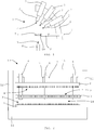
- Fig. 1 shows a schematic representation of a first embodiment of the warp knitting machine 1 according to the invention with three laying bars 2 and a piercing bar 3 in a side view.
- Each laying bar 2 carries laying needles 4.
- the laying needles 4 are provided for guiding warp threads and shift the warp threads according to a desired laying.
- the piercing bar 3 carries a plurality of hold-down devices 5.
- the laying bars 2 and the piercing bar 3 are firmly connected to one another via a supporting body 6.
- Holding arms 7 connect the laying bars 2 and the piercing bar 3 to the supporting body 6.
- the warp knitting machine 1 also has a knitting needle bar 8 with knitting needles 9.
- the knitting needle bar 8 is connected to a machine bed of the warp knitting machine 1 via support levers (not shown) and is set into an approximately elliptical movement during operation of the warp knitting machine 1 so that it catches the warp threads guided by the laying bars 2.
- the knitting needle 9 moves upwards and laterally past the hold-down device 5, which holds a warp thread on a needle shaft of the knitting needle 9, thereby preventing the warp thread from rising with the knitting needle 9.
- the hold-down 5 has a hole 10 for guiding elastane threads. He can thus take over the function of a bar 2.
- the support body 6 is attached to a side wall of the warp knitting machine 1, not shown. The support body 6 is stationary, so it does not move when the warp knitting machine 1 is in operation.
- Fig. 2 shows a schematic representation of a second embodiment of the warp knitting machine 1 according to the invention.
- the warp knitting machine 1 has a laying bar 2 with laying needles 4, a piercing bar 3 with hold-downs 5 and a knitting needle bar 8 with knitting needles 9.
- the laying bar 2 and the piercing bar 3 are connected to one another via a plurality of supporting bodies 6.
- Holding arms 7 establish a connection between the support body 6 and the bar 2.
- the laying bar 2 is attached to the holding arms 7 so as to be displaceable along its longitudinal direction and, in the present illustration, is shifted slightly to the left.
- the warp knitting machine 1 also has a machine bed 11. Drive elements for driving the knitting needle bar 8, the laying bar 2 and other knitting tool carriers of the warp knitting machine 1 are arranged in this.
- Two side walls 12 extend from the machine bed 11. The side walls 12 are connected to one another via a cross member 13. According to this embodiment, the supporting bodies 6 are fastened to the cross member 13. Since the comb bar 3 is suspended together with the bar 2, no additional support element for the comb bar 3 is required. Below the piercing bar 3 there is a free working space 14.
Landscapes
- Engineering & Computer Science (AREA)
- Textile Engineering (AREA)
- Knitting Machines (AREA)
- Knitting Of Fabric (AREA)
Abstract
Description
- Die Erfindung betrifft eine Kettenwirkmaschine mit einer Wirknadelbarre, an der Wirknadeln befestigt sind, mit einer Legebarre, an der Legenadeln befestigt sind, und mit einer Stechkammbarre, wobei die Stechkammbarre Niederhalter aufweist, die dazu vorgesehen sind, eine von der Kettenwirkmaschine erzeugte Wirkware niederzuhalten, wenn die Wirknadelbarre in Richtung der Legebarre aufsteigt.
- Kettenwirkmaschinen weisen Wirkwerkzeuge auf, die Kettfäden bei einem Wirkprozess zu einem flächigen Textilmaterial, einer sogenannten Wirkware, verarbeiten. Kettenwirkmaschinen weisen ferner mehrere Barren auf, wobei an einer Barre jeweils eine Vielzahl von Wirkwerkzeugen angeordnet sind. Unter einer Barre ist ein Halteelement zu verstehen, das beispielsweise aus einem Metall oder einem faserverstärkten Kunststoff gefertigt sein kann. Da mittels einer Barre eine Vielzahl von Wirkwerkzeugen gleichzeitig bewegt werden können, werden bei dem Wirkprozess eine Vielzahl von Maschen gleichzeitig gebildet. Zu den gängigen Wirkwerkzeugen zählen Wirknadeln und Legenadeln. Einige Kettenwirkmaschinen weisen ferner Niederhalter auf. Deren Zweck wird nachfolgend beschrieben. Bei dem Wirkprozess steigen die Wirknadeln in Richtung der Legebarren auf, um einen Kettfaden zu fangen. Dabei kann ein an der Wirknadel anliegender Kettfaden aufgrund von Reibungskräften mit nach oben steigen. Dies wird durch die Niederhalter verhindert, die beim Aufsteigen der Wirknadeln zwischen die Wirknadeln greifen. Mehrere Niederhalter bilden gemeinsam einen sogenannten Stechkamm.
- Niederhalter und die sie tragenden Stechkammbarren sind aus dem Stand der Technik bekannt. So zeigt die
DE 19719125 A1 eine Kettenwirkmaschine mit einer Stechkammbarre, die durch einen Antrieb in einem Maschinenbett der Kettenwirkmaschine beweglich ist. Bei der dargestellten Kettenwirkmaschine vom Typ einer Raschelmaschine lässt sich eine Position einer Abschlagkammbarre relativ zu der Stechkammbarre ändern. DieDE 19755634 A1 beschreibt ebenfalls eine Raschelmaschine, die eine Stechkammbarre aufweist. - Bekannte Kettenwirkmaschinen stützen die Stechkammbarre von unten. Es werden somit stets ein oder mehrere Stützelemente benötigt, die die Stechkammbarre tragen. Der dazu notwendige Aufbau kann materialaufwändig sein und verbraucht Platz, der stattdessen für andere Maschinenelemente genutzt werden könnte. Vibrationen aus dem Bereich des Maschinenbetts, die über das Stützelement übertragen werden, können sich negativ auf die Qualität der erzeugten Wirkware auswirken. Der Erfindung liegt deshalb die Aufgabe zu Grunde, die bestehenden Nachteile bei der Anbringung der Stechkammbarre zu beheben.
- Die Aufgabe wird gelöst, indem eine Kettenwirkmaschine der eingangs genannten Gattung bereitgestellt wird, bei der die Stechkammbarre mit der Legebarre verbunden ist. Die Stechkammbarre wird direkt oder indirekt an der Legebarre befestigt. Hierdurch ergibt sich ein einfacher und platzsparender Aufbau. Die Verbindung des Stechkamms mit der Legebarre ist der Qualität der erzeugten Wirkware nicht abträglich.
- Die Stechkammbarre ist mit der Legebarre vorzugsweise durch mindestens einen Tragkörper verbunden. Es können zusätzliche Verbindungselemente zum Einsatz kommen, sodass die Stechkammbarre und/oder die Legebarre indirekt mit dem Tragkörper in Verbindung steht. So kann gemäß einer Variante der Erfindung die Legebarre mittels eines Haltearms oder mehrerer Haltearme an dem Tragkörper befestigt sein. Der Tragkörper kann erfindungsgemäß aus einem Metall oder einer Metalllegierung gefertigt sein. Es kann erfindungsgemäß mehr als ein Tragkörper zum Einsatz kommen, um die Legebarre und die Stechkammbarre zu halten.
- Es ist bevorzugt, wenn die Stechkammbare mit der Legebarre nicht über eine Seitenwand, eine Traverse und/oder ein Maschinenbett der Kettenwirkmaschine verbunden ist. Bevorzugt ist der Tragkörper auch nicht Teil von einer Seitenwand, einer Traverse und/oder eines Maschinenbetts der Kettenwirkmaschine. Es sollte es sich bei dem Tragkörper bevorzugt um ein von einer Seitenwand, einer Traverse und/oder Traverse separates Bauteil handeln. Bei einem Maschinenbett handelt es sich um ein Basiselement einer Kettenwirkmaschine, das einen Hohlraum bildet, in dem Antriebselemente der Kettenwirkmaschine angeordnet sind. Bei einer Seitenwand handelt es sich um ein stützendes Bauteil einer Kettenwirkmaschine, das sich vertikal aus dem Maschinenbett in die Höhe erstreckt. Bei einer Traverse handelt es sich um ein tragfähiges Bauteil einer Kettenwirkmaschine, das an mindestens zwei Seitenwänden einer Kettenwirkmaschine befestigt ist. Gemäß einer vorteilhaften Ausführungsform der Erfindung sind sämtliche Elemente des Tragkörpers und/oder sonstige Verbindungselemente, die die Stechkammbarre mit der Legebarre verbinden, ober- und außerhalb des Maschinenbetts angeordnet.
- Es ist vorteilhaft, wenn an dem Tragkörper mehrere Legebarren befestigt sind. Der Tragkörper trägt somit mehrere Legebarren und darüber hinaus auch noch die Stechkammbarre. Es ergibt sich eine kompakte Aufhängung mehrerer Legebarren und der Stechkammbarre an dem Tragkörper.
- Gemäß einer besonderen Ausführungsform der Erfindung ist die Stechkammbarre an dem Tragkörper unterhalb der Legebarre befestigt. Wenn mehrere Legebarren an dem Tragkörper befestigt sind, dann versteht es sich, dass auch dann die Stechkammbarre diejenige Barre bildet, die zuunterst angeordnet ist. Dieser Aufbau ist deshalb sinnvoll, da ein von der Kettenwirkmaschine geführter Kettfaden zunächst durch Legenadeln hindurchläuft, bevor er die Wirknadeln erreicht. Örtlich zwischen den Wirknadeln und den Legenadeln sind die Niederhalter angeordnet, die durch die Stechkammbarre getragen werden.
- Die Stechkammbarre wird bevorzugt ausschließlich durch einen oder mehrere Tragkörper getragen, wobei jeder der Tragkörper auch eine Legebarre trägt. Die Tragkörper können in Längsrichtung der Legebarre versetzt an der Kettenwirkmaschine vorgesehen sein. Vorzugsweise wird die Stechkammbarre nicht durch ein Stützelement gestützt, das sich ausgehend von einem Maschinenbett der Kettenwirkmaschine in Richtung der Stechkammbarre erstreckt.
- Es kann erfindungsgemäß vorgesehen sein, dass der Tragkörper eine gekrümmte Form aufweist, wobei an dem Tragkörper befestigte Barren auf einer Seite des Tragkörpers angeordnet sind, die eine konkave Oberfläche aufweist. Der Tragkörper weist somit eine Form auf, die eine Ausrichtung der daran angebrachten Legebarren ermöglicht, bei der die Legenadeln unterschiedlicher Legebarren sehr nahe beieinander angeordnet sind. Dies ist vorteilhaft, da bei einem solchen Aufbau die an der Maschenbildung beteiligten Wirkwerkzeuge nur sehr kurze Wege zurücklegen müssen.
- Die an dem Tragkörper befestigen Barren sind vorzugsweise zueinander fächerförmig angeordnet. Bei einer Ansicht auf Stirnseiten der Barren ist somit ein fächerförmiges Profil erkennbar. Somit sind die Legenadeln besonders nahe beieinander angeordnet und insbesondere die Wirknadeln müssen bei dem Wirkprozess nur sehr kurze Wege zurücklegen. Dadurch ergibt sich wiederum eine höhere Wirkgeschwindigkeit und ein niedrigerer Energiebedarf der Kettenwirkmaschine.
- Es ist vorteilhaft, wenn der Tragkörper an einer Seitenwand oder an einer Traverse der Kettenwirkmaschine befestigt ist. Dies dient der Befestigung des Tragkörpers. Somit wird der Tragkörper an der Kettenwirkmaschine gestützt.
- Der Tragkörper ist beim Betrieb der Kettenwirkmaschine vorzugsweise ortsfest. Dies bedeutet, dass der Tragkörper beim Betrieb der Kettenwirkmaschine nicht verlagerbar ist, nicht verschwenkbar ist oder in sonstiger Weise seine Position ändern kann. Dies ist maschinendynamisch vorteilhaft, da nun nicht eine große, sowohl durch die Stechkammbarre als auch durch die mindestens eine an dem Tragkörper befestigte Legebarre gebildete Masse mittels des Tragkörpers bewegt werden muss. Gemäß Ausführungsformen der Erfindung kann es gleichwohl vorgesehen sein, dass der Tragkörper verschwenkbar an einem tragenden Bauteil der Kettenwirkmaschine aufgehängt ist, sodass sowohl die Stechkammbarre als auch die mindestens eine Legebarre in einer Richtung quer zu einer Längsrichtung der Stechkammbarre beziehungsweise der Legebarre verlagerbar ist.
- Es ist bevorzugt, wenn die Legebarre in ihrer Längsrichtung relativ zu dem Tragkörper verlagerbar ist. Ganz besonders bevorzugt ist die Legebarre ausschließlich in ihrer Längsrichtung relativ zu dem Tragkörper verlagerbar. Wenn der Tragkörper beim Betrieb der Kettenwirkmaschine ortsfest ist, dann führt die Legebarre keine Schwingbewegung in einer Richtung quer zu ihrer Längsrichtung aus. Hingegen kann die Wirknadelbarre eine Durchschwingbewegung ausführen, sodass die Wirknadeln der Wirknadelbarre an den Legenadeln der Legebarre vorbeischwingen. Eine für den Wirkprozess notwendige Ein- und Ausschwingbewegung der Wirkelemente ist somit gegeben. Damit die Wirknadeln zwischen unterschiedlichen Legenadeln hindurchschwingen können, wird die Legebarre entlang ihrer Längsrichtung verlagert. Dazu können erfindungsgemäß Aufsatzelemente der Legebarre auf Zapfen verlagerbar aufsitzen.
- Die Stechkammbarre ist beim Betrieb der Kettenwirkmaschine vorzugsweise ortsfest. Dies bedeutet, dass die Stechkammbarre beim Betrieb der Kettenwirkmaschine nicht verlagerbar ist, nicht verschwenkbar ist oder in sonstiger Weise ihre Position ändern kann. Dies kann erfindungsgemäß dadurch bewirkt sein, dass die Stechkammbarre an einem Tragkörper befestigt ist, der wiederum ortsfest ist. Die Stechkammbarre ist bevorzugt fest und nicht verlagerbar an dem Tragkörper angebracht.
- Es ist vorteilhaft, wenn die Kettenwirkmaschine ein Getriebe aufweist, das dazu eingerichtet ist, eine Gangbewegung der Wirknadelbarre herbeizuführen, bei der die an der Wirknadelbarre befestigen Wirknadeln beim Aufsteigen in Richtung der Legebarre durch Zwischenräume zwischen den Niederhaltern hindurchbewegt werden. Die Niederhalter verhindern dabei, dass an den Wirknadeln anliegende Kettfäden und eine durch diese gebildete Wirkware beim Aufsteigen der Wirknadeln ebenfalls aufsteigen. Stattdessen halten die Niederhalter die Wirkware in einem unteren Schaftbereich der Wirknadeln.
- Vorangehend wurden unterschiedliche Bewegungseigenschaften von Barren der erfindungsgemäßen Kettenwirkmaschine beschrieben. Die erfindungsgemäße Kettenwirkmaschine kann aber auch durchaus so betrieben werden, dass die Barren abweichende Bewegungseigenschaften aufweisen. Die erfindungsgemäße Verbindung der Stechkammbarre mit der Legebarre ist auch dann vorteilhaft und technisch umsetzbar.
- Es ist vorteilhaft, wenn die Niederhalter Löcher zur Führung von Kettfäden aufweisen. Die Niederhalter können somit zusätzlich die Funktion von Legenadeln übernehmen. Bei manchen Ausführungsformen bedeutet dies, dass eine Legebarre eingespart werden kann. Die Löcher eignen sich insbesondere zur Führung von elastischen Kettfäden.
- Gemäß einer bevorzugten Ausführungsform der Erfindung handelt es sich bei der Kettenwirkmaschine um eine Raschelmaschine. Bei Raschelmaschinen steigt die Wirkware beim Aufsteigen der Wirknadeln häufig nach oben, was den Einsatz eines Niederhalter aufweisenden Stechkamms erforderlich macht.
- Bei den Wirknadeln kann es sich erfindungsgemäß um Schiebernadeln, Spitzennadeln, Zungennadeln oder Wirknadeln sonstigen Typs handeln. Bei den Legenadeln kann es sich erfindungsgemäß um Lochnadeln handeln.
- Die Zeichnungen stellen bevorzugte Ausführungsformen der Erfindung dar. Dabei zeigt:
-
Fig. 1 eine schematische Darstellung einer ersten Ausführungsform der erfindungsgemäßen Kettenwirkmaschine mit drei Legebarren und einer Stechkammbarre in einer Seitenansicht und -
Fig. 2 eine schematische Darstellung einer zweiten Ausführungsform der erfindungsgemäßen Kettenwirkmaschine mit einer Legebarre und einer Stechkammbarre in einer Frontalansicht. -
Fig. 1 zeigt eine schematische Darstellung einer ersten Ausführungsform der erfindungsgemäßen Kettenwirkmaschine 1 mit drei Legebarren 2 und einer Stechkammbarre 3 in einer Seitenansicht. Jede Legebarre 2 trägt Legenadeln 4. Die Legenadeln 4 sind zur Führung von Kettfäden vorgesehen und verlagern die Kettfäden entsprechend einer gewünschten Legung. Die Stechkammbarre 3 trägt mehrere Niederhalter 5. Die Legebarren 2 und die Stechkammbarre 3 sind über einen Tragkörper 6 fest miteinander verbunden. Haltearme 7 verbinden die Legebarren 2 und die Stechkammbarre 3 mit dem Tragkörper 6. Die Kettenwirkmaschine 1 weist ferner eine Wirknadelbarre 8 mit Wirknadeln 9 auf. Die Wirknadelbarre 8 ist über nicht dargestellte Traghebel mit einem Maschinenbett der Kettenwirkmaschine 1 verbunden und wird beim Betrieb der Kettenwirkmaschine 1 in eine ungefähr elliptische Gangbewegung versetzt, sodass sie die von den Legebarren 2 geführten Kettfäden fängt. Dabei bewegt sich die Wirknadel 9 aufwärts und seitlich an dem Niederhalter 5 vorbei, der dabei einen Kettfaden auf einem Nadelschaft der Wirknadel 9 hält, wodurch verhindert wird, dass der Kettfaden mit der Wirknadel 9 nach oben steigt. - Der Niederhalter 5 weist ein Loch 10 zur Führung von Elastanfäden auf. Er kann somit die Funktion einer Legebarre 2 übernehmen. Der Tragkörper 6 ist an einer nicht dargestellten Seitenwand der Kettenwirkmaschine 1 befestigt. Der Tragkörper 6 ist stationär, bewegt sich also beim Betrieb der Kettenwirkmaschine 1 nicht.
-
Fig. 2 zeigt eine schematische Darstellung einer zweiten Ausführungsform der erfindungsgemäßen Kettenwirkmaschine 1. - Die Kettenwirkmaschine 1 weist eine Legebarre 2 mit Legenadeln 4, eine Stechkammbarre 3 mit Niederhaltern 5 und eine Wirknadelbarre 8 mit Wirknadeln 9 auf. Die Legebarre 2 und die Stechkammbarre 3 sind miteinander über mehrere Tragkörper 6 verbunden. Haltearme 7 stellen eine Verbindung zwischen dem Tragkörper 6 und der Legebarre 2 her. Die Legebarre 2 ist an den Haltearmen 7 entlang ihrer Längsrichtung verlagerbar angebracht und in vorliegender Darstellung leicht nach links verlagert.
- Die Kettenwirkmaschine 1 weist ferner ein Maschinenbett 11 auf. In diesem sind Antriebselemente zum Antrieb der Wirknadelbarre 8, der Legebarre 2 und sonstiger Wirkwerkzeugträger der Kettenwirkmaschine 1 angeordnet. Aus dem Maschinenbett 11 erstrecken sich zwei Seitenwände 12. Die Seitenwände 12 sind über eine Traverse 13 miteinander verbunden. Die Tragkörper 6 sind gemäß dieser Ausführungsform an der Traverse 13 befestigt. Da die Stechkammbarre 3 gemeinsam mit der Legebarre 2 aufgehängt ist, ist kein zusätzliches Stützelement für die Stechkammbarre 3 erforderlich. Unterhalb der Stechkammbarre 3 ergibt sich ein freibleibender Arbeitsraum 14.
-
- 1.
- Kettenwirkmaschine
- 2.
- Legebarre
- 3.
- Stechkammbarre
- 4.
- Legenadel
- 5.
- Niederhalter
- 6.
- Tragkörper
- 7.
- Haltearm
- 8.
- Wirknadelbarre
- 9.
- Wirknadel
- 10.
- Loch
- 11.
- Maschinenbett
- 12.
- Seitenwand
- 13.
- Traverse
- 14.
- Arbeitsraum
Claims (15)
- Kettenwirkmaschine (1) mit einer Wirknadelbarre (8), an der Wirknadeln (9) befestigt sind, mit einer Legebarre (2), an der Legenadeln (4) befestigt sind, und mit einer Stechkammbarre (3), wobei die Stechkammbarre (3) Niederhalter (5) aufweist, die dazu vorgesehen sind, eine von der Kettenwirkmaschine (1) erzeugte Wirkware niederzuhalten, wenn die Wirknadelbarre (8) in Richtung der Legebarre (2) aufsteigt, dadurch gekennzeichnet, dass die Stechkammbarre (3) mit der Legebarre (2) verbunden ist.
- Kettenwirkmaschine (1) nach Anspruch 1, dadurch gekennzeichnet, dass die Stechkammbarre (3) mit der Legebarre (2) durch mindestens einen Tragkörper (6) verbunden ist.
- Kettenwirkmaschine (1) nach Anspruch 1 oder 2, dadurch gekennzeichnet, dass die Stechkammbare (3) mit der Legebarre nicht über eine Seitenwand (12), eine Traverse (13) und/oder ein Maschinenbett (11) der Kettenwirkmaschine (1) verbunden ist.
- Kettenwirkmaschine (1) nach einem der Ansprüche 2 oder 3, dadurch gekennzeichnet, dass an dem Tragkörper (6) mehrere Legebarren (2) befestigt sind.
- Kettenwirkmaschine (1) nach einem der Ansprüche 2 bis 4, dadurch gekennzeichnet, dass die Stechkammbarre (3) an dem Tragkörper (6) unterhalb der Legebarre (2) befestigt ist.
- Kettenwirkmaschine (1) nach einem der Ansprüche 2 bis 5, dadurch gekennzeichnet, dass die Stechkammbarre (3) ausschließlich durch einen oder mehrere Tragkörper (6) getragen wird, wobei jeder der Tragkörper (6) auch eine Legebarre (2) trägt.
- Kettenwirkmaschine (1) nach einem der Ansprüche 2 bis 6, dadurch gekennzeichnet, dass der Tragkörper (6) eine gekrümmte Form aufweist, wobei an dem Tragkörper (6) befestigte Barren (2, 3) auf einer Seite des Tragkörpers (6) angeordnet sind, die eine konkave Oberfläche aufweist.
- Kettenwirkmaschine (1) nach einem der Ansprüche 2 bis 7, dadurch gekennzeichnet, dass die an dem Tragkörper (6) befestigen Barren (2, 3) zueinander fächerförmig angeordnet sind.
- Kettenwirkmaschine (1) nach einem der Ansprüche 2 bis 8, dadurch gekennzeichnet, dass der Tragkörper (6) an einer Seitenwand (12) oder einer Traverse (13) der Kettenwirkmaschine (1) befestigt ist.
- Kettenwirkmaschine (1) nach einem der Ansprüche 2 bis 9, dadurch gekennzeichnet, dass der Tragkörper (6) beim Betrieb der Kettenwirkmaschine (1) ortsfest ist.
- Kettenwirkmaschine (1) nach einem der Ansprüche 2 bis 10, dadurch gekennzeichnet, dass die Legebarre (2) in ihrer Längsrichtung relativ zu dem Tragkörper (6) verlagerbar ist.
- Kettenwirkmaschine (1) nach einem der vorhergehenden Ansprüche, dadurch gekennzeichnet, dass die Stechkammbarre (3) beim Betrieb der Kettenwirkmaschine (1) ortsfest ist.
- Kettenwirkmaschine (1) nach einem der vorhergehenden Ansprüche, dadurch gekennzeichnet, dass die Kettenwirkmaschine (1) ein Getriebe aufweist, das dazu eingerichtet ist, eine Gangbewegung der Wirknadelbarre (8) herbeizuführen, bei der die an der Wirknadelbarre (8) befestigen Wirknadeln (9) beim Aufsteigen in Richtung der Legebarre (2) durch Zwischenräume zwischen den Niederhaltern (5) hindurchbewegt werden.
- Kettenwirkmaschine (1) nach einem der vorhergehenden Ansprüche, dadurch gekennzeichnet, dass die Niederhalter (5) Löcher (10) zur Führung von Kettfäden aufweisen.
- Kettenwirkmaschine (1) nach einem der vorhergehenden Ansprüche, dadurch gekennzeichnet, dass die Kettenwirkmaschine (1) eine Raschelmaschine ist.
Priority Applications (2)
| Application Number | Priority Date | Filing Date | Title |
|---|---|---|---|
| EP19211907.1A EP3617358B1 (de) | 2019-11-27 | 2019-11-27 | Kettenwirkmaschine |
| CN202010069063.8A CN112853598B (zh) | 2019-11-27 | 2020-01-21 | 经编机 |
Applications Claiming Priority (1)
| Application Number | Priority Date | Filing Date | Title |
|---|---|---|---|
| EP19211907.1A EP3617358B1 (de) | 2019-11-27 | 2019-11-27 | Kettenwirkmaschine |
Publications (3)
| Publication Number | Publication Date |
|---|---|
| EP3617358A2 true EP3617358A2 (de) | 2020-03-04 |
| EP3617358A3 EP3617358A3 (de) | 2020-07-08 |
| EP3617358B1 EP3617358B1 (de) | 2022-07-27 |
Family
ID=68731713
Family Applications (1)
| Application Number | Title | Priority Date | Filing Date |
|---|---|---|---|
| EP19211907.1A Active EP3617358B1 (de) | 2019-11-27 | 2019-11-27 | Kettenwirkmaschine |
Country Status (2)
| Country | Link |
|---|---|
| EP (1) | EP3617358B1 (de) |
| CN (1) | CN112853598B (de) |
Citations (2)
| Publication number | Priority date | Publication date | Assignee | Title |
|---|---|---|---|---|
| DE19719125A1 (de) | 1997-05-07 | 1998-11-12 | Mayer Textilmaschf | Raschelmaschine mit Stechkammbarre und Abschlagkammbarre |
| DE19755634A1 (de) | 1997-12-15 | 1999-06-17 | Mayer Malimo Textilmaschf | Kettenwirkmaschine, insbesondere Raschelmaschine, mit Schiebernadeln |
Family Cites Families (5)
| Publication number | Priority date | Publication date | Assignee | Title |
|---|---|---|---|---|
| GB797215A (en) * | 1955-06-21 | 1958-06-25 | F N F Machinery Mfg Company Lt | Improvements relating to warp knitting machinery |
| DE2123273C3 (de) * | 1971-05-11 | 1973-11-08 | Karl Mayer, Textil-Maschinenfabrik Gmbh, 6053 Obertshausen | Kettenwirkmaschine mit Spitzen nadeln und Platinen |
| US3857260A (en) * | 1972-06-05 | 1974-12-31 | A Zwingenberger | Sinker arrangement for warp knitting and raschel machines |
| GB2214527A (en) * | 1988-02-04 | 1989-09-06 | Kutaissky Politekhn I Im N Mus | Method of loop formation in a warp-knitting machine |
| CN1038319A (zh) * | 1988-06-04 | 1989-12-27 | 库塔伊西·波利特查斯研究所 | 经编机的成圈方法及实现该方法的成圈装置 |
-
2019
- 2019-11-27 EP EP19211907.1A patent/EP3617358B1/de active Active
-
2020
- 2020-01-21 CN CN202010069063.8A patent/CN112853598B/zh active Active
Patent Citations (2)
| Publication number | Priority date | Publication date | Assignee | Title |
|---|---|---|---|---|
| DE19719125A1 (de) | 1997-05-07 | 1998-11-12 | Mayer Textilmaschf | Raschelmaschine mit Stechkammbarre und Abschlagkammbarre |
| DE19755634A1 (de) | 1997-12-15 | 1999-06-17 | Mayer Malimo Textilmaschf | Kettenwirkmaschine, insbesondere Raschelmaschine, mit Schiebernadeln |
Also Published As
| Publication number | Publication date |
|---|---|
| CN112853598B (zh) | 2022-07-22 |
| CN112853598A (zh) | 2021-05-28 |
| EP3617358A3 (de) | 2020-07-08 |
| EP3617358B1 (de) | 2022-07-27 |
Similar Documents
| Publication | Publication Date | Title |
|---|---|---|
| DE3321733C2 (de) | Kettenwirkmaschine mit Jacquard-Lochnadeln | |
| EP2045385A1 (de) | Wirkwerkzeuganordnung und Wirkwerkzeug | |
| AT407651B (de) | Vorrichtung zum nadeln eines vlieses | |
| DE19651053C1 (de) | Kettenwirkmaschine mit Jacquard-Legebarre | |
| DE102012000309A1 (de) | Wirkmaschine zum Abarbeiten von mindestens zwei Warenbahnen | |
| EP3643823A1 (de) | Kettenwirkmaschinen-schiebernadel | |
| EP3299501A1 (de) | Kettenwirkmaschine | |
| EP3095904A1 (de) | Legebarrenanordnung einer kettenwirkmaschine | |
| EP3530790B1 (de) | Schiebernadel | |
| DE10335464B4 (de) | Verfahren zum maschinellen Maschenbilden mit zugehörigen Maschenbildungselementen | |
| DE4446953A1 (de) | Garnführung und Garnführungseinheit für eine Jacquard-Strickmaschine | |
| EP3617358B1 (de) | Kettenwirkmaschine | |
| EP3594392A1 (de) | Kettenwirkmaschine mit einem schwingungsdämpfer | |
| DE3728513A1 (de) | Niederhaltevorrichtung fuer durch jacquardmaschinen gesteuerte webmaschinen | |
| DE3023952A1 (de) | Kettenwirkmaschine | |
| DE19920673C2 (de) | Platinen-Segment | |
| EP2570540B1 (de) | Wirkwerkzeugfassung | |
| DE2145305C3 (de) | ||
| DE102010032996B4 (de) | Legebarrenanordnung einer Kettenwirkmaschine | |
| EP3859067B1 (de) | Kettenwirkmaschine | |
| EP3354780B1 (de) | Kettenwirkmaschine | |
| EP3418434B1 (de) | Maschinenstrickwerkzeug, insbesondere maschinenstricknadel | |
| DE2846792C2 (de) | Doppelhub-Offenfach-Jacquardmaschine | |
| EP3216903A1 (de) | Kettenwirkmaschine | |
| EP2679712B1 (de) | Fallblechanordnung einer Kettenwirkmaschine |
Legal Events
| Date | Code | Title | Description |
|---|---|---|---|
| PUAI | Public reference made under article 153(3) epc to a published international application that has entered the european phase |
Free format text: ORIGINAL CODE: 0009012 |
|
| STAA | Information on the status of an ep patent application or granted ep patent |
Free format text: STATUS: THE APPLICATION HAS BEEN PUBLISHED |
|
| AK | Designated contracting states |
Kind code of ref document: A2 Designated state(s): AL AT BE BG CH CY CZ DE DK EE ES FI FR GB GR HR HU IE IS IT LI LT LU LV MC MK MT NL NO PL PT RO RS SE SI SK SM TR |
|
| AX | Request for extension of the european patent |
Extension state: BA ME |
|
| PUAL | Search report despatched |
Free format text: ORIGINAL CODE: 0009013 |
|
| AK | Designated contracting states |
Kind code of ref document: A3 Designated state(s): AL AT BE BG CH CY CZ DE DK EE ES FI FR GB GR HR HU IE IS IT LI LT LU LV MC MK MT NL NO PL PT RO RS SE SI SK SM TR |
|
| AX | Request for extension of the european patent |
Extension state: BA ME |
|
| RIC1 | Information provided on ipc code assigned before grant |
Ipc: D04B 27/24 20060101ALI20200602BHEP Ipc: D04B 27/06 20060101AFI20200602BHEP |
|
| RAP1 | Party data changed (applicant data changed or rights of an application transferred) |
Owner name: KARL MAYER STOLL R&D GMBH |
|
| STAA | Information on the status of an ep patent application or granted ep patent |
Free format text: STATUS: REQUEST FOR EXAMINATION WAS MADE |
|
| 17P | Request for examination filed |
Effective date: 20201124 |
|
| RBV | Designated contracting states (corrected) |
Designated state(s): AL AT BE BG CH CY CZ DE DK EE ES FI FR GB GR HR HU IE IS IT LI LT LU LV MC MK MT NL NO PL PT RO RS SE SI SK SM TR |
|
| STAA | Information on the status of an ep patent application or granted ep patent |
Free format text: STATUS: EXAMINATION IS IN PROGRESS |
|
| 17Q | First examination report despatched |
Effective date: 20210601 |
|
| GRAP | Despatch of communication of intention to grant a patent |
Free format text: ORIGINAL CODE: EPIDOSNIGR1 |
|
| STAA | Information on the status of an ep patent application or granted ep patent |
Free format text: STATUS: GRANT OF PATENT IS INTENDED |
|
| INTG | Intention to grant announced |
Effective date: 20220302 |
|
| GRAS | Grant fee paid |
Free format text: ORIGINAL CODE: EPIDOSNIGR3 |
|
| GRAA | (expected) grant |
Free format text: ORIGINAL CODE: 0009210 |
|
| STAA | Information on the status of an ep patent application or granted ep patent |
Free format text: STATUS: THE PATENT HAS BEEN GRANTED |
|
| AK | Designated contracting states |
Kind code of ref document: B1 Designated state(s): AL AT BE BG CH CY CZ DE DK EE ES FI FR GB GR HR HU IE IS IT LI LT LU LV MC MK MT NL NO PL PT RO RS SE SI SK SM TR |
|
| REG | Reference to a national code |
Ref country code: CH Ref legal event code: EP |
|
| REG | Reference to a national code |
Ref country code: AT Ref legal event code: REF Ref document number: 1507139 Country of ref document: AT Kind code of ref document: T Effective date: 20220815 |
|
| REG | Reference to a national code |
Ref country code: DE Ref legal event code: R096 Ref document number: 502019005066 Country of ref document: DE |
|
| REG | Reference to a national code |
Ref country code: IE Ref legal event code: FG4D Free format text: LANGUAGE OF EP DOCUMENT: GERMAN |
|
| REG | Reference to a national code |
Ref country code: LT Ref legal event code: MG9D |
|
| REG | Reference to a national code |
Ref country code: NL Ref legal event code: MP Effective date: 20220727 |
|
| PG25 | Lapsed in a contracting state [announced via postgrant information from national office to epo] |
Ref country code: SE Free format text: LAPSE BECAUSE OF FAILURE TO SUBMIT A TRANSLATION OF THE DESCRIPTION OR TO PAY THE FEE WITHIN THE PRESCRIBED TIME-LIMIT Effective date: 20220727 Ref country code: RS Free format text: LAPSE BECAUSE OF FAILURE TO SUBMIT A TRANSLATION OF THE DESCRIPTION OR TO PAY THE FEE WITHIN THE PRESCRIBED TIME-LIMIT Effective date: 20220727 Ref country code: PT Free format text: LAPSE BECAUSE OF FAILURE TO SUBMIT A TRANSLATION OF THE DESCRIPTION OR TO PAY THE FEE WITHIN THE PRESCRIBED TIME-LIMIT Effective date: 20221128 Ref country code: NO Free format text: LAPSE BECAUSE OF FAILURE TO SUBMIT A TRANSLATION OF THE DESCRIPTION OR TO PAY THE FEE WITHIN THE PRESCRIBED TIME-LIMIT Effective date: 20221027 Ref country code: NL Free format text: LAPSE BECAUSE OF FAILURE TO SUBMIT A TRANSLATION OF THE DESCRIPTION OR TO PAY THE FEE WITHIN THE PRESCRIBED TIME-LIMIT Effective date: 20220727 Ref country code: LV Free format text: LAPSE BECAUSE OF FAILURE TO SUBMIT A TRANSLATION OF THE DESCRIPTION OR TO PAY THE FEE WITHIN THE PRESCRIBED TIME-LIMIT Effective date: 20220727 Ref country code: LT Free format text: LAPSE BECAUSE OF FAILURE TO SUBMIT A TRANSLATION OF THE DESCRIPTION OR TO PAY THE FEE WITHIN THE PRESCRIBED TIME-LIMIT Effective date: 20220727 Ref country code: FI Free format text: LAPSE BECAUSE OF FAILURE TO SUBMIT A TRANSLATION OF THE DESCRIPTION OR TO PAY THE FEE WITHIN THE PRESCRIBED TIME-LIMIT Effective date: 20220727 Ref country code: ES Free format text: LAPSE BECAUSE OF FAILURE TO SUBMIT A TRANSLATION OF THE DESCRIPTION OR TO PAY THE FEE WITHIN THE PRESCRIBED TIME-LIMIT Effective date: 20220727 |
|
| PG25 | Lapsed in a contracting state [announced via postgrant information from national office to epo] |
Ref country code: PL Free format text: LAPSE BECAUSE OF FAILURE TO SUBMIT A TRANSLATION OF THE DESCRIPTION OR TO PAY THE FEE WITHIN THE PRESCRIBED TIME-LIMIT Effective date: 20220727 Ref country code: IS Free format text: LAPSE BECAUSE OF FAILURE TO SUBMIT A TRANSLATION OF THE DESCRIPTION OR TO PAY THE FEE WITHIN THE PRESCRIBED TIME-LIMIT Effective date: 20221127 Ref country code: HR Free format text: LAPSE BECAUSE OF FAILURE TO SUBMIT A TRANSLATION OF THE DESCRIPTION OR TO PAY THE FEE WITHIN THE PRESCRIBED TIME-LIMIT Effective date: 20220727 Ref country code: GR Free format text: LAPSE BECAUSE OF FAILURE TO SUBMIT A TRANSLATION OF THE DESCRIPTION OR TO PAY THE FEE WITHIN THE PRESCRIBED TIME-LIMIT Effective date: 20221028 |
|
| PG25 | Lapsed in a contracting state [announced via postgrant information from national office to epo] |
Ref country code: SM Free format text: LAPSE BECAUSE OF FAILURE TO SUBMIT A TRANSLATION OF THE DESCRIPTION OR TO PAY THE FEE WITHIN THE PRESCRIBED TIME-LIMIT Effective date: 20220727 Ref country code: RO Free format text: LAPSE BECAUSE OF FAILURE TO SUBMIT A TRANSLATION OF THE DESCRIPTION OR TO PAY THE FEE WITHIN THE PRESCRIBED TIME-LIMIT Effective date: 20220727 Ref country code: DK Free format text: LAPSE BECAUSE OF FAILURE TO SUBMIT A TRANSLATION OF THE DESCRIPTION OR TO PAY THE FEE WITHIN THE PRESCRIBED TIME-LIMIT Effective date: 20220727 Ref country code: CZ Free format text: LAPSE BECAUSE OF FAILURE TO SUBMIT A TRANSLATION OF THE DESCRIPTION OR TO PAY THE FEE WITHIN THE PRESCRIBED TIME-LIMIT Effective date: 20220727 |
|
| REG | Reference to a national code |
Ref country code: DE Ref legal event code: R097 Ref document number: 502019005066 Country of ref document: DE |
|
| PG25 | Lapsed in a contracting state [announced via postgrant information from national office to epo] |
Ref country code: SK Free format text: LAPSE BECAUSE OF FAILURE TO SUBMIT A TRANSLATION OF THE DESCRIPTION OR TO PAY THE FEE WITHIN THE PRESCRIBED TIME-LIMIT Effective date: 20220727 Ref country code: EE Free format text: LAPSE BECAUSE OF FAILURE TO SUBMIT A TRANSLATION OF THE DESCRIPTION OR TO PAY THE FEE WITHIN THE PRESCRIBED TIME-LIMIT Effective date: 20220727 |
|
| PLBE | No opposition filed within time limit |
Free format text: ORIGINAL CODE: 0009261 |
|
| STAA | Information on the status of an ep patent application or granted ep patent |
Free format text: STATUS: NO OPPOSITION FILED WITHIN TIME LIMIT |
|
| PG25 | Lapsed in a contracting state [announced via postgrant information from national office to epo] |
Ref country code: MC Free format text: LAPSE BECAUSE OF FAILURE TO SUBMIT A TRANSLATION OF THE DESCRIPTION OR TO PAY THE FEE WITHIN THE PRESCRIBED TIME-LIMIT Effective date: 20220727 Ref country code: AL Free format text: LAPSE BECAUSE OF FAILURE TO SUBMIT A TRANSLATION OF THE DESCRIPTION OR TO PAY THE FEE WITHIN THE PRESCRIBED TIME-LIMIT Effective date: 20220727 |
|
| REG | Reference to a national code |
Ref country code: CH Ref legal event code: PL |
|
| 26N | No opposition filed |
Effective date: 20230502 |
|
| REG | Reference to a national code |
Ref country code: BE Ref legal event code: MM Effective date: 20221130 |
|
| PG25 | Lapsed in a contracting state [announced via postgrant information from national office to epo] |
Ref country code: LI Free format text: LAPSE BECAUSE OF NON-PAYMENT OF DUE FEES Effective date: 20221130 Ref country code: CH Free format text: LAPSE BECAUSE OF NON-PAYMENT OF DUE FEES Effective date: 20221130 |
|
| P01 | Opt-out of the competence of the unified patent court (upc) registered |
Effective date: 20230704 |
|
| PG25 | Lapsed in a contracting state [announced via postgrant information from national office to epo] |
Ref country code: SI Free format text: LAPSE BECAUSE OF FAILURE TO SUBMIT A TRANSLATION OF THE DESCRIPTION OR TO PAY THE FEE WITHIN THE PRESCRIBED TIME-LIMIT Effective date: 20220727 Ref country code: LU Free format text: LAPSE BECAUSE OF NON-PAYMENT OF DUE FEES Effective date: 20221127 |
|
| PG25 | Lapsed in a contracting state [announced via postgrant information from national office to epo] |
Ref country code: IE Free format text: LAPSE BECAUSE OF NON-PAYMENT OF DUE FEES Effective date: 20221127 |
|
| PG25 | Lapsed in a contracting state [announced via postgrant information from national office to epo] |
Ref country code: FR Free format text: LAPSE BECAUSE OF NON-PAYMENT OF DUE FEES Effective date: 20221130 Ref country code: BE Free format text: LAPSE BECAUSE OF NON-PAYMENT OF DUE FEES Effective date: 20221130 |
|
| PG25 | Lapsed in a contracting state [announced via postgrant information from national office to epo] |
Ref country code: HU Free format text: LAPSE BECAUSE OF FAILURE TO SUBMIT A TRANSLATION OF THE DESCRIPTION OR TO PAY THE FEE WITHIN THE PRESCRIBED TIME-LIMIT; INVALID AB INITIO Effective date: 20191127 |
|
| PG25 | Lapsed in a contracting state [announced via postgrant information from national office to epo] |
Ref country code: CY Free format text: LAPSE BECAUSE OF FAILURE TO SUBMIT A TRANSLATION OF THE DESCRIPTION OR TO PAY THE FEE WITHIN THE PRESCRIBED TIME-LIMIT Effective date: 20220727 |
|
| PG25 | Lapsed in a contracting state [announced via postgrant information from national office to epo] |
Ref country code: MK Free format text: LAPSE BECAUSE OF FAILURE TO SUBMIT A TRANSLATION OF THE DESCRIPTION OR TO PAY THE FEE WITHIN THE PRESCRIBED TIME-LIMIT Effective date: 20220727 |
|
| GBPC | Gb: european patent ceased through non-payment of renewal fee |
Effective date: 20231127 |
|
| PG25 | Lapsed in a contracting state [announced via postgrant information from national office to epo] |
Ref country code: BG Free format text: LAPSE BECAUSE OF FAILURE TO SUBMIT A TRANSLATION OF THE DESCRIPTION OR TO PAY THE FEE WITHIN THE PRESCRIBED TIME-LIMIT Effective date: 20220727 |
|
| PG25 | Lapsed in a contracting state [announced via postgrant information from national office to epo] |
Ref country code: MT Free format text: LAPSE BECAUSE OF FAILURE TO SUBMIT A TRANSLATION OF THE DESCRIPTION OR TO PAY THE FEE WITHIN THE PRESCRIBED TIME-LIMIT Effective date: 20220727 |
|
| PG25 | Lapsed in a contracting state [announced via postgrant information from national office to epo] |
Ref country code: GB Free format text: LAPSE BECAUSE OF NON-PAYMENT OF DUE FEES Effective date: 20231127 |
|
| PG25 | Lapsed in a contracting state [announced via postgrant information from national office to epo] |
Ref country code: GB Free format text: LAPSE BECAUSE OF NON-PAYMENT OF DUE FEES Effective date: 20231127 |
|
| PGFP | Annual fee paid to national office [announced via postgrant information from national office to epo] |
Ref country code: IT Payment date: 20241125 Year of fee payment: 6 |
|
| PGFP | Annual fee paid to national office [announced via postgrant information from national office to epo] |
Ref country code: DE Payment date: 20251126 Year of fee payment: 7 |
|
| PG25 | Lapsed in a contracting state [announced via postgrant information from national office to epo] |
Ref country code: AT Free format text: LAPSE BECAUSE OF NON-PAYMENT OF DUE FEES Effective date: 20241127 |
|
| REG | Reference to a national code |
Ref country code: AT Ref legal event code: MM01 Ref document number: 1507139 Country of ref document: AT Kind code of ref document: T Effective date: 20241127 |
|
| PGFP | Annual fee paid to national office [announced via postgrant information from national office to epo] |
Ref country code: TR Payment date: 20251106 Year of fee payment: 7 |
|
| PGFP | Annual fee paid to national office [announced via postgrant information from national office to epo] |
Ref country code: AT Payment date: 20260410 Year of fee payment: 5 |