EP3608469B1 - Wäschetrockner und verfahren zum trocknen von wäsche mit einem wäschetrockner - Google Patents
Wäschetrockner und verfahren zum trocknen von wäsche mit einem wäschetrockner Download PDFInfo
- Publication number
- EP3608469B1 EP3608469B1 EP19186484.2A EP19186484A EP3608469B1 EP 3608469 B1 EP3608469 B1 EP 3608469B1 EP 19186484 A EP19186484 A EP 19186484A EP 3608469 B1 EP3608469 B1 EP 3608469B1
- Authority
- EP
- European Patent Office
- Prior art keywords
- fan
- air
- drum
- humidity
- temperature
- Prior art date
- Legal status (The legal status is an assumption and is not a legal conclusion. Google has not performed a legal analysis and makes no representation as to the accuracy of the status listed.)
- Active
Links
Images

Classifications
-
- D—TEXTILES; PAPER
- D06—TREATMENT OF TEXTILES OR THE LIKE; LAUNDERING; FLEXIBLE MATERIALS NOT OTHERWISE PROVIDED FOR
- D06F—LAUNDERING, DRYING, IRONING, PRESSING OR FOLDING TEXTILE ARTICLES
- D06F58/00—Domestic laundry dryers
- D06F58/32—Control of operations performed in domestic laundry dryers
- D06F58/34—Control of operations performed in domestic laundry dryers characterised by the purpose or target of the control
- D06F58/36—Control of operational steps, e.g. for optimisation or improvement of operational steps depending on the condition of the laundry
- D06F58/38—Control of operational steps, e.g. for optimisation or improvement of operational steps depending on the condition of the laundry of drying, e.g. to achieve the target humidity
-
- D—TEXTILES; PAPER
- D06—TREATMENT OF TEXTILES OR THE LIKE; LAUNDERING; FLEXIBLE MATERIALS NOT OTHERWISE PROVIDED FOR
- D06F—LAUNDERING, DRYING, IRONING, PRESSING OR FOLDING TEXTILE ARTICLES
- D06F58/00—Domestic laundry dryers
- D06F58/20—General details of domestic laundry dryers
-
- D—TEXTILES; PAPER
- D06—TREATMENT OF TEXTILES OR THE LIKE; LAUNDERING; FLEXIBLE MATERIALS NOT OTHERWISE PROVIDED FOR
- D06F—LAUNDERING, DRYING, IRONING, PRESSING OR FOLDING TEXTILE ARTICLES
- D06F2103/00—Parameters monitored or detected for the control of domestic laundry washing machines, washer-dryers or laundry dryers
- D06F2103/02—Characteristics of laundry or load
- D06F2103/08—Humidity
-
- D—TEXTILES; PAPER
- D06—TREATMENT OF TEXTILES OR THE LIKE; LAUNDERING; FLEXIBLE MATERIALS NOT OTHERWISE PROVIDED FOR
- D06F—LAUNDERING, DRYING, IRONING, PRESSING OR FOLDING TEXTILE ARTICLES
- D06F2103/00—Parameters monitored or detected for the control of domestic laundry washing machines, washer-dryers or laundry dryers
- D06F2103/28—Air properties
- D06F2103/32—Temperature
-
- D—TEXTILES; PAPER
- D06—TREATMENT OF TEXTILES OR THE LIKE; LAUNDERING; FLEXIBLE MATERIALS NOT OTHERWISE PROVIDED FOR
- D06F—LAUNDERING, DRYING, IRONING, PRESSING OR FOLDING TEXTILE ARTICLES
- D06F2103/00—Parameters monitored or detected for the control of domestic laundry washing machines, washer-dryers or laundry dryers
- D06F2103/28—Air properties
- D06F2103/34—Humidity
-
- D—TEXTILES; PAPER
- D06—TREATMENT OF TEXTILES OR THE LIKE; LAUNDERING; FLEXIBLE MATERIALS NOT OTHERWISE PROVIDED FOR
- D06F—LAUNDERING, DRYING, IRONING, PRESSING OR FOLDING TEXTILE ARTICLES
- D06F2103/00—Parameters monitored or detected for the control of domestic laundry washing machines, washer-dryers or laundry dryers
- D06F2103/28—Air properties
- D06F2103/36—Flow or velocity
-
- D—TEXTILES; PAPER
- D06—TREATMENT OF TEXTILES OR THE LIKE; LAUNDERING; FLEXIBLE MATERIALS NOT OTHERWISE PROVIDED FOR
- D06F—LAUNDERING, DRYING, IRONING, PRESSING OR FOLDING TEXTILE ARTICLES
- D06F2103/00—Parameters monitored or detected for the control of domestic laundry washing machines, washer-dryers or laundry dryers
- D06F2103/38—Time, e.g. duration
-
- D—TEXTILES; PAPER
- D06—TREATMENT OF TEXTILES OR THE LIKE; LAUNDERING; FLEXIBLE MATERIALS NOT OTHERWISE PROVIDED FOR
- D06F—LAUNDERING, DRYING, IRONING, PRESSING OR FOLDING TEXTILE ARTICLES
- D06F2103/00—Parameters monitored or detected for the control of domestic laundry washing machines, washer-dryers or laundry dryers
- D06F2103/44—Current or voltage
-
- D—TEXTILES; PAPER
- D06—TREATMENT OF TEXTILES OR THE LIKE; LAUNDERING; FLEXIBLE MATERIALS NOT OTHERWISE PROVIDED FOR
- D06F—LAUNDERING, DRYING, IRONING, PRESSING OR FOLDING TEXTILE ARTICLES
- D06F2103/00—Parameters monitored or detected for the control of domestic laundry washing machines, washer-dryers or laundry dryers
- D06F2103/52—Parameters monitored or detected for the control of domestic laundry washing machines, washer-dryers or laundry dryers related to electric heating means, e.g. temperature or voltage
-
- D—TEXTILES; PAPER
- D06—TREATMENT OF TEXTILES OR THE LIKE; LAUNDERING; FLEXIBLE MATERIALS NOT OTHERWISE PROVIDED FOR
- D06F—LAUNDERING, DRYING, IRONING, PRESSING OR FOLDING TEXTILE ARTICLES
- D06F2103/00—Parameters monitored or detected for the control of domestic laundry washing machines, washer-dryers or laundry dryers
- D06F2103/54—Parameters monitored or detected for the control of domestic laundry washing machines, washer-dryers or laundry dryers related to blowers or fans
-
- D—TEXTILES; PAPER
- D06—TREATMENT OF TEXTILES OR THE LIKE; LAUNDERING; FLEXIBLE MATERIALS NOT OTHERWISE PROVIDED FOR
- D06F—LAUNDERING, DRYING, IRONING, PRESSING OR FOLDING TEXTILE ARTICLES
- D06F2105/00—Systems or parameters controlled or affected by the control systems of washing machines, washer-dryers or laundry dryers
- D06F2105/16—Air properties
- D06F2105/24—Flow or velocity
-
- D—TEXTILES; PAPER
- D06—TREATMENT OF TEXTILES OR THE LIKE; LAUNDERING; FLEXIBLE MATERIALS NOT OTHERWISE PROVIDED FOR
- D06F—LAUNDERING, DRYING, IRONING, PRESSING OR FOLDING TEXTILE ARTICLES
- D06F2105/00—Systems or parameters controlled or affected by the control systems of washing machines, washer-dryers or laundry dryers
- D06F2105/28—Electric heating
-
- D—TEXTILES; PAPER
- D06—TREATMENT OF TEXTILES OR THE LIKE; LAUNDERING; FLEXIBLE MATERIALS NOT OTHERWISE PROVIDED FOR
- D06F—LAUNDERING, DRYING, IRONING, PRESSING OR FOLDING TEXTILE ARTICLES
- D06F2105/00—Systems or parameters controlled or affected by the control systems of washing machines, washer-dryers or laundry dryers
- D06F2105/30—Blowers
-
- D—TEXTILES; PAPER
- D06—TREATMENT OF TEXTILES OR THE LIKE; LAUNDERING; FLEXIBLE MATERIALS NOT OTHERWISE PROVIDED FOR
- D06F—LAUNDERING, DRYING, IRONING, PRESSING OR FOLDING TEXTILE ARTICLES
- D06F2105/00—Systems or parameters controlled or affected by the control systems of washing machines, washer-dryers or laundry dryers
- D06F2105/32—Air flow control means
-
- D—TEXTILES; PAPER
- D06—TREATMENT OF TEXTILES OR THE LIKE; LAUNDERING; FLEXIBLE MATERIALS NOT OTHERWISE PROVIDED FOR
- D06F—LAUNDERING, DRYING, IRONING, PRESSING OR FOLDING TEXTILE ARTICLES
- D06F34/00—Details of control systems for washing machines, washer-dryers or laundry dryers
- D06F34/14—Arrangements for detecting or measuring specific parameters
- D06F34/26—Condition of the drying air, e.g. air humidity or temperature
-
- D—TEXTILES; PAPER
- D06—TREATMENT OF TEXTILES OR THE LIKE; LAUNDERING; FLEXIBLE MATERIALS NOT OTHERWISE PROVIDED FOR
- D06F—LAUNDERING, DRYING, IRONING, PRESSING OR FOLDING TEXTILE ARTICLES
- D06F58/00—Domestic laundry dryers
- D06F58/02—Domestic laundry dryers having dryer drums rotating about a horizontal axis
-
- D—TEXTILES; PAPER
- D06—TREATMENT OF TEXTILES OR THE LIKE; LAUNDERING; FLEXIBLE MATERIALS NOT OTHERWISE PROVIDED FOR
- D06F—LAUNDERING, DRYING, IRONING, PRESSING OR FOLDING TEXTILE ARTICLES
- D06F58/00—Domestic laundry dryers
- D06F58/20—General details of domestic laundry dryers
- D06F58/26—Heating arrangements, e.g. gas heating equipment
Definitions
- the invention relates to a tumble dryer and a method for drying laundry to be dried using a tumble dryer.
- tumble dryers are known, with a tumble dryer quite commonly having a drum including a drive, air supply and air discharge. A fan is also provided to blow heated air into the tumble dryer via the air supply. Air discharged from the drum at the air outlet is then dehumidified in different ways. To dry laundry, the same amount of heat or equally warm air is often always introduced into the drum. A moisture measurement takes place either in the drum or in the air discharged from the drum. If a certain desired degree of drying is recognized, it is defined that the end of the drying process has been reached and the dryer stops.
- a tumble dryer is known with a drum and a drum drive.
- a discrete dry sensor is provided for this purpose. This can be used to determine the moisture content of the laundry in the drum.
- a tumble dryer and a method for controlling is known, wherein a humidity sensor unit has a discrete humidity sensor, which is arranged adjacent to a drying drum. This allows the degree of moisture in the laundry in the drum to be determined directly.
- a tumble dryer and a method for its operation are known in which a discrete moisture sensor is arranged next to a temperature sensor in an air duct away from the drum.
- the humidity in the exhaust air can be determined using the discrete humidity sensor.
- a fan which can heat conveyed air.
- two induction heating coils are arranged on the valve housing, which are controlled accordingly can become.
- You can inductively heat a part of the rotor of the fan, which is made of a suitable material, for example iron. This can be provided for a base plate of the rotor, for example.
- the invention is based on the object of creating a tumble dryer as mentioned at the outset and a method as mentioned at the outset with which problems of the prior art can be solved and in particular it is possible to dry laundry quickly, efficiently and also as gently as possible.
- a laundry dryer according to the invention has a drum for receiving laundry to be dried and a drive motor for the drum.
- An air exhaust towards the drum as well as an air exhaust away from the drum are provided. These are advantageously channels with a large cross section, as is customary per se.
- An airflow fan is provided to move the airflow toward the drum through the air duct. The same fan sucks air out of the drum or away from the drum through the mentioned air discharge.
- the fan has its own fan drive, which in principle can be of a very general type.
- heating means are provided for heating the air flow, which is essential for the drying function.
- Temperature sensing means are provided to sense the temperature of the air fed into the drum or, alternatively, the air exhausted from the drum. Provision can also be made for detecting the temperature of the air in both cases.
- Humidity detection means are also provided for correspondingly detecting a humidity of the air fed into the drum and/or the air discharged from the drum. According to the invention, the humidity of the air that is discharged from the drum is measured in any case, in order to obtain information about how much humidity is still present in the drum or how damp the laundry is. The temperature can be recorded in a similar way.
- the tumble dryer has a control which, on the one hand, has a memory in which at least one default curve for the progression of temperature and/or humidity over time for a specific laundry drying program is stored.
- This drying program can be adapted to the type of laundry or its main fiber content and to a user's preference as to whether drying should take place gently or quickly.
- the controller also has arithmetic means that are designed to compare values for temperature and/or moisture currently recorded during a drying program, depending on the drying phase in the laundry, with an aforementioned default curve. In this way it can be determined at which operating point of the default curve the drying program is located. The currently recorded values for temperature and/or humidity are used for this purpose.
- Either only one default curve is provided, in which case the working point can be determined directly within this default curve.
- a number of different default curves can also be provided for this specific drying program, for example depending on the load quantity. Then the most suitable default curve can also be determined by comparison with the recorded values, and then the working point can be determined within this default curve.
- the controller is designed to influence the further drying program or the further drying process on the basis of the operating point determined.
- it can be optimized, for which purpose the temperature of the air flow can be adjusted or changed by influencing the heating means.
- the strength of the air flow can be adjusted by influencing the fan, ie air can be supplied to the drum to a greater or lesser extent or blown into it.
- the controller can also cause or control a drum movement or the drive motor for the drum separately and as desired. By adapting the drum movement, a named method for determining the temperature and/or humidity of the laundry can be optimally supported.
- the invention influence the further course of the drying program with regard to the temperature and/or strength of the air flow in order to advantageously reduce the temperature of the air flow to the drum during the last quarter of the drying program below the average of the previously used temperature of the to reduce airflow.
- the temperature can particularly advantageously be lowered at least 5°C below this average, possibly even lowered at least 15°C up to 20°C.
- the air flow rate to the drum should be increased above the average of the previously used air flow rates, advantageously increased by at least 20%, most advantageously increased by at least 50%.
- the knowledge can thus be implemented that during the last quarter of the drying program the laundry is already largely or largely dry and is very warm in the outer area or in the outer layers. Further or continued heating brings only little or nothing here, so that energy can be saved by lowering the temperature of the supplied air and the laundry can also be protected. Rather, the increased blowing in of air at the end of drying then removes the moisture from the already strongly heated laundry better.
- Drying in a tumble dryer is mainly done by air drying.
- temperature, air throughput and drum movement are coordinated in such a way that a consistently good drying result is achieved.
- contact drying could possibly be provided, preferably by heating the drum.
- the strength of the air flow can be reduced at the beginning of the drying program, in particular during the first third or the first quarter of the estimated duration, and its temperature can be increased for this purpose.
- the laundry to be dried which is still very damp or has almost the initial moisture content, can be heated as quickly as possible so that the moisture on the material surface can then evaporate better.
- the air supply In order to achieve the best possible effect for the air supply, it can be provided that it is provided at most 10% of the diameter of the drum below its highest point.
- the air supply can even be provided at the highest point of the drum. This ensures that the air supply is not directly covered by laundry or unintentionally sealed. Furthermore, in the event that air is also sucked off at the air supply in order to record the temperature and/or the humidity of the air in the drum, this recording can be prevented as little as possible by laundry located close to it.
- the fan direction or the direction of the air flow is reversed several times at intervals. Air can then be sucked out of the drum into the air supply, not at the air discharge but at the air supply. Information about the exhaust air or the air from the drum is obtained from this. According to the invention, this is information regarding the humidity of the exhaust air, which can be used for the aforementioned determination of the working point on a default curve or for determining the default curve itself. This is also information regarding the temperature of the exhaust air, if applicable. This is particularly advantageous when the temperature detection means and the humidity detection means are arranged in the air supply close to the drum. This is explained in more detail below.
- the fan is preferably arranged close to the drum.
- a distance can be a maximum of 50 cm from the drum, preferably a maximum of 30 cm or even only 20 cm.
- the fan drive in an advantageous embodiment of the present invention is its own drive that only for the fan is provided.
- the fan drive forms a structural unit together with the fan. Suitable power electronics are provided for controlling the fan drive, which can advantageously be steplessly adjusted.
- this is known in the prior art and is not a problem.
- the fan has an inductively heatable fan rotor, which thus forms a heating means for heating the air flow for the drum.
- the fan rotor can have a plurality of fan blades, wherein at least one fan blade consists at least partially of material that can be heated by means of a magnetic field generating means or has such a material.
- This material is preferably provided in a radially outer area of the fan rotor or the fan blades, as a result of which it can be arranged as close as possible to the magnetic field generation means mentioned. Provision can be made for a fan blade to be formed entirely from such a material. With inductive heating of this fan blade, the air conveyed by it can thus be heated as well as possible.
- the magnetic field generating means are preferably arranged adjacent to the fan rotor and/or can at least partially surround it. They can also be arranged in or on a fan housing.
- An example of such an inductively heatable fan is known from DE 102017210527.5 the same applicant with the filing date of June 22, 2017.
- the at least one magnetic field generating means has at least one induction coil or is such an induction coil.
- a single induction heating coil is advantageously provided for a fan.
- it can be wound around the fan rotor radially outside of the fan rotor, so that its coil axis coincides with the axis of rotation of the fan rotor.
- a plurality of induction coils may be arranged around the fan rotor adjacent to one another such that their coil axes are perpendicular to and point towards the axis of the fan rotor.
- the temperature detection means to include the fan rotor and the magnetic field generation means in the form of the induction coil.
- the temperature of the inductively heatable fan blade or of the inductively heatable fan rotor can be detected from the activation of the induction coil and thus also the temperature of the air flow generated by the fan or the conveyed air.
- Such an inductive temperature measurement is generally known to those skilled in the art for induction heaters, for example in the field of induction hobs including induction heating coils.
- the temperature of the air blown into the drum can thus be detected in order to regulate the heating means to a desired temperature.
- the temperature of the air extracted directly from the drum can be measured. In this way, the temperature in the drum can be recorded almost directly, so to speak.
- the heating means for heating the air flow can simultaneously form the temperature detection means.
- a separate temperature sensor can be saved by using the fan or the fan rotor for temperature measurement.
- any heating means can be provided; even inductive heating of the fan rotor can be provided in the embodiment described above by means of at least one permanent magnet. This can be arranged alone or together with other permanent magnets near the fan rotor in a form similar to the induction coils described above for inductive heating of the fan rotor.
- a complex induction generator for the aforementioned induction coils can then be dispensed with, which significantly reduces the number of components.
- a magnetic field generating means for an inductively heatable fan rotor can be arranged outside of a fan housing or outside of the air supply. In this way, an air flow is impaired as little as possible.
- Such a magnetic field generating means can extend radially outside the fan rotor, preferably only at the axial level of the fan rotor and not above or below it.
- the moisture detection means mentioned at the outset are implemented in or through the fan or comprise the fan and its drive. This is because the humidity of the conveyed air can be determined from the activation of the fan drive. This utilizes the fact that when there is high humidity in the air moved by the fan, a high torque has to be provided by the drive, while when there is low humidity in the air moved by the fan, a lower torque has to be provided. This is simply due to the fact that the specific density is higher in the first case than in the second case, so that in the first case more power or a higher torque has to be provided by the fan drive. During normal operation of the fan to draw air into the drum via the air duct, a such detection of humidity in the air is not necessary.
- the humidity here will usually be relatively low. Rather, the moisture in the air sucked out of the drum is detected with this option when the fan direction or the direction of the air flow is reversed as mentioned above. Since a separate fan drive with its own control is provided anyway, this is also used as a moisture detection means. Then separate moisture detection means can be dispensed with.
- a phase shift between current and voltage in the fan drive is advantageously monitored to evaluate whether a high or a low torque is to be produced by the fan drive. In this way, the level of said torque can be determined, this relationship being known in principle to a person skilled in the art.
- the inside of the drum of the tumble dryer according to the invention is free of sensors. In this way, it can be designed in a simplified manner with increased operational reliability, since no sensors can break.
- the drum may also not have any sensors on its outside, as a result of which it can also be designed in a simple and reliable manner in this regard.
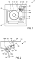
- a tumble dryer 11 can be basically constructed according to the invention.
- the tumble dryer 11 has a housing 12 with a drum 14 which is arranged in a drum receptacle 18 .
- the drum 14 can be driven by a drum drive 15 by means of a drive belt 16, as is basically known.
- the drum 14 usually rotates at a single possible rotational speed, which then also remains constant. However, this can also be varied.
- the drum 14 has no sensors or the like here. especially not for temperature or humidity.
- a channel-like air supply 20 approaches the drum receptacle 18 at the top right, as is known per se from the prior art. This elevated position is important and beneficial, as previously explained.
- a fan 21 together with a fan rotor 22 and a fan drive 24 is arranged in the air supply 20, advantageously as a structural unit.
- the fan rotor 22 is made of inductively heatable material, especially the individual rotor blades. It can thus be inductively heated by two induction coils 26a and 26b arranged outside the air supply 20 opposite the fan rotor 22 and surrounding it. This is also known from the prior art. The heating can be varied depending on the strength of the magnetic field generated by the induction coils 26a and 26b and also depending on the speed of the fan rotor 22.
- Such a fan 21, which can be heated inductively is known.
- the drum drive 15, the fan drive 24 and the induction coils 26a and 26b are connected to a controller 28 of the tumble dryer 11. This carries out the method explained at the outset as well as the other operations of the tumble dryer.
- the controller 28 advantageously has an appropriately designed processor.
- an air discharge 40 is also arranged on the drum receptacle 18 at the top left, which leads to a condenser 42 in that water is separated from the moist air that is sucked out of the drum 14 in a known manner.
- the drum 14, air discharge 40 and air supply 20 form a kind of circuit, the air in it being moved or circulated counterclockwise, so to speak. This ventilation direction corresponds to normal, customary dry operation.
- the tumble dryer 11 can also use a heat pump or dehumidify the air sucked out of the drum 14 at the air discharge 40 in some other way.
- the controller 28 is designed to determine the temperature of the fan rotor 22 or the inductively heatable parts present on it based on the activation of the induction coils 26a and 26b. The temperature of the air flowing past it can thus be recorded indirectly, which is also advantageous or even necessary in normal heating operation. Furthermore, the controller 28 controls the fan drive 24 of the fan 21 so that it knows or can determine the power to be applied. From this, as explained at the outset, conclusions can be drawn about the humidity in the transported air. Finally, the controller 28 can advantageously contain a converter or inverter for the fan drive 24 or can be designed as a structural unit therewith. It can also have an induction generator for driving the induction coils 26a and 26b or form a structural unit therewith. Thus, in one embodiment of the invention, a central control unit could be provided, which takes over the aforementioned control functions and a power supply.
- the controller can also be a combination of an inverter and a controller or microcontroller and measuring means, for example a current measuring coil or a current shunt. A zero-crossing detection can also be provided.
- an alternative tumble dryer 111 is shown as a variation in an enlarged view, which has an additional outlet 130 in its housing 112 .
- This outlet 130 opens into a branch 132 which branches off at the top from the air supply 120 or is connected to it. It is closed by a branch flap 134, which can be opened downwards and closed upwards by a flap actuator 136, ie it can be moved.
- the flap actuator 136 can be a rod drive, alternatively an electromagnet or the like.
- a smaller second fan rotor 123 is attached to a fan 121 on the same shaft on which a larger first fan rotor 122 is also seated.
- the second fan rotor 123 is designed to convey air in the opposite direction of rotation to the first fan rotor 122 . If the fan drive 124 rotates in its normal direction, then the first fan rotor 122 conveys air through the air supply 120 according to the large arrow into the drum receptacle 118 and thus also into the drum 114 according to normal operation. It can be heated in the manner described above by induction coils 126a and 126b in order to heat the conveyed air for dryer operation.
- the second fan rotor 123 can also consist partially or entirely of inductively heatable material.
- the fan drive 124 rotates in the opposite direction of rotation for which the second fan rotor 123 is designed, the air flow is generated according to the thinner arrow and air is sucked out of the drum 114 into the air supply 120 .
- the branch flap 134 is open downwards and is shown in broken lines, this air flows upwards through the outlet 130, out of the housing 112 here by way of example.
- it could also be routed back into the duct of the air discharge 40 via a return, as a result of which the escape of fluff can be reduced or avoided.
- this air from the drum 114 does not have to be heated, here the heating function by means of the induction coils 126a and 126b serves to detect the temperature of this extracted air in this way.
- the first fan rotor 122 can have no effect in this second opposite conveying direction; it may be able to contribute to the conveying of air in this direction, but this is not necessary.
- the second fan rotor 123 is provided for this purpose.
- Is according to the 1 only a single fan rotor 22 provided on the fan 21, it should be designed for operation in both directions. A significantly better degree of efficiency can be provided for blowing air through the air supply 20 into the drum 14, but it should also be possible, at least in principle, in the other direction.
- the fan drive 24 or 124 which is independent of the drum drive 15, allows the fan 21 or 121 to be operated as desired and independently.
- the extraction of air from the drum 114 to detect the temperature of this air does not have to be long, for example it can be as short as 2 seconds to 10 seconds.
- the instantaneous power of the fan drive 124 can also generally be detected by monitoring the fan drive 124 and its operating values. From this, as explained above, the humidity of the extracted air and thus inside the drum 114 can be determined. The more power the fan drive 124 has to apply for suction at a specific speed, the more humid this air is. The wetter the laundry in drum 114 is then.
- Determining the humidity of the air discharged from the drum, possibly also the air fed into the drum 114, is advantageously carried out by determining a phase shift in the fan drive 124, since the required torque changes with the dependency of the viscosity of the air on its moisture content. Air with a high moisture content is simply more difficult to transport than dry air. A corresponding reference in the controller or a previous "calibration" in dry air allows this determination. Such a measurement can be taken at the in 2 shown double fan 121 can be performed well. The difference between sucking the air out of the drum 114 and blowing air into the drum is measured. Useful information about this process can be obtained from the difference.
- the heating of the air via the inductively heated fan rotor 22 or 122 or 123 allows the energy absorbed by the induction coils 126a and 126b to be evaluated in parallel.
- the profile of the energy consumed can be seen on an induction generator (not shown) via corresponding control variables, which provides information about the temperature of the fan rotors, since a comparison with existing characteristic curves is possible.
- a dynamic electromagnetic excitation of the induction coils 126a and 126b can provide further information about the temperature of the air.
- the change compared to known characteristic curves can also Indicate the humidity of the air or its change.
- the combination of the two pieces of information from the recording of moisture and temperature allows the process to be carried out independently of direct temperature measurement, since known characteristic values can be recorded and compared with those actually present in the process.
- This enables process-oriented control of the humidity and ideal air temperature parameters.
- Known parameters such as outside temperature and pressure, which are measured here with sensors, can also support the control.
- the influences of the laundry which are very random due to their different composition, can be recognized more quickly, since other parameters such as drum movement and thus laundry movement can be included in the evaluation of the measurement results.
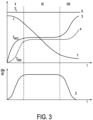
- Curve 1 is the relative humidity or humidity of the laundry.
- Parameter 2 in the diagram below is the mass flow of removed moisture, given in kg/(m 2 s).
- the parameter of curve 3 is the surface temperature T WO of the laundry.
- the course 4 of the corresponding Parameters shows the core temperature T WK of the laundry, and curve 5 is the temperature T L of the air supplied. All temperatures are given in °C.
- section I the laundry is heated and the moisture on the material surface is evaporated.
- the drying intensity is not great, because on the one hand the heat transferred is not only needed to evaporate the moisture, but above all to heat the entire laundry.
- the thermal moisture conductivity which increases due to the temperature difference between the surface and the core, slows down the removal of moisture.
- thermal moisture conductivity is that the moisture content of the laundry changes constantly during drying. This creates a concentration gradient between the textile surface, from which moisture is continuously removed, and the inner layers of the laundry items, which causes a moisture transport from places with higher to places with lower moisture concentration according to moisture diffusion, also known as moisture conductivity.
- the moisture is therefore transported to the surface of the laundry or to the location of the evaporation limit, where it is converted into steam, which mixes with the heated air, and is discharged into the environment.
- the evaporation limit moves from the surface of the laundry into the interior of the laundry.
- the material to be dried is heated in addition to removing the moisture.
- the heat supply via the surface creates a temperature difference between the surface and the inner layers or the core.
- the drying rate decreases again. With increasing heating, the evaporation limit moves from the surface into the inner layers or the core of the laundry. The heat supplied via the air is no longer used only or mainly for evaporating the moisture, but increasingly for heating the laundry.
- the partial pressure difference between the inner and outer layers of the laundry is crucial for the transport of moisture to the surface of the laundry.
- the removal of moisture from the laundry is complete and the temperature of the laundry is approaching the temperature of the air.
- the drying speed depends on the conditions of heat transfer at the laundry surface and the distance of the water vapor from the evaporation line.
- the humidity f W still decreases, but this decrease flattens out. Accordingly, the humidity f L also decreases greatly.
- the last phase 4 which lasts about 5 minutes, hardly any moisture can be removed into the air, but the laundry is dry or completely dry, since its moisture content f W reaches zero or even slightly below.
- FIG 5 is accordingly closed 4 divided into the four phases a curve for the temperature T L of the discharged air shown with triangles during the same drying process.
- a curve for the temperature T W of the laundry is also shown with rectangles. It roughly corresponds to the core temperature T WK of the curve 4 in 3 .
- the temperature T W of the laundry like the moisture f W of the laundry, has been determined experimentally.
- phase 1 the temperature T L is increased rapidly to around 40°C.
- phase 2 the temperature T L is again increased to just over 50 °C.
- phase 1 the temperature of the laundry T W , which is shown as a rectangle, increases with a delay. Then, during phase 2, a temperature rise is greatly reduced.
- phase 1 it is recommended to accelerate the process of increasing the temperature of the laundry so that evaporation begins as quickly as possible.
- the temperature T W is equal to the temperature T L , so that the energy supplied is used for evaporation.
- phase 3 an increase in the temperature T L makes little or no sense, since this only leads to an increase in the temperature T W and not to an acceleration of evaporation due to the thermodynamic effects.
- Phase 4 is necessary because of the non-uniform moisture distribution, which is more difficult to remove because it is "bound moisture".
- the decisive factor here is the combination of heat output, air rate or convection and drum movement. Furthermore, the focus is on the heating capacity.
- a combination of an air heating system with an integrated heater in the fan allows the measurement function to be optimized with fewer components and increased data acquisition.
- the aim is to use indirect information from the process for the process.
- parameters that are directly related to the convection and evaporation of water in the dryer should be recorded and used for process control.
- a mentioned method for detecting parameters for the process control can be optimally supported by the mentioned possibility of any control of the drum movement or the drive motor for the drum.
Landscapes
- Engineering & Computer Science (AREA)
- Textile Engineering (AREA)
- Control Of Washing Machine And Dryer (AREA)
- Detail Structures Of Washing Machines And Dryers (AREA)
Applications Claiming Priority (1)
| Application Number | Priority Date | Filing Date | Title |
|---|---|---|---|
| DE102018213108.2A DE102018213108A1 (de) | 2018-08-06 | 2018-08-06 | Wäschetrockner und Verfahren zum Trocknen von Wäsche mit einem Wäschetrockner |
Publications (3)
| Publication Number | Publication Date |
|---|---|
| EP3608469A2 EP3608469A2 (de) | 2020-02-12 |
| EP3608469A3 EP3608469A3 (de) | 2020-05-06 |
| EP3608469B1 true EP3608469B1 (de) | 2023-08-30 |
Family
ID=67314643
Family Applications (1)
| Application Number | Title | Priority Date | Filing Date |
|---|---|---|---|
| EP19186484.2A Active EP3608469B1 (de) | 2018-08-06 | 2019-07-16 | Wäschetrockner und verfahren zum trocknen von wäsche mit einem wäschetrockner |
Country Status (4)
| Country | Link |
|---|---|
| US (1) | US11021837B2 (pl) |
| EP (1) | EP3608469B1 (pl) |
| DE (1) | DE102018213108A1 (pl) |
| PL (1) | PL3608469T3 (pl) |
Families Citing this family (11)
| Publication number | Priority date | Publication date | Assignee | Title |
|---|---|---|---|---|
| US10487443B1 (en) * | 2015-10-30 | 2019-11-26 | Cool Dry, Inc. | Hybrid RF/conventional clothes dryer |
| DE102016000226A1 (de) * | 2016-01-14 | 2017-07-20 | Herbert Kannegiesser Gmbh | Vorrichtung zum Mangeln von Wäschestücken |
| DE102018213108A1 (de) * | 2018-08-06 | 2020-02-06 | E.G.O. Elektro-Gerätebau GmbH | Wäschetrockner und Verfahren zum Trocknen von Wäsche mit einem Wäschetrockner |
| KR102695866B1 (ko) * | 2019-01-04 | 2024-08-19 | 엘지전자 주식회사 | 의류처리장치 및 그 제어방법 |
| EP3696313A1 (de) * | 2019-02-15 | 2020-08-19 | Miele & Cie. KG | Wäschepflegegerät, vorzugsweise trockner |
| US12366025B2 (en) | 2020-03-16 | 2025-07-22 | Lg Electronics Inc. | Laundry treating apparatus |
| EP4123078A4 (en) * | 2020-03-16 | 2024-04-03 | LG Electronics Inc. | GARMENT PROCESSING DEVICE |
| DE102020111604A1 (de) | 2020-04-29 | 2021-11-04 | Miele & Cie. Kg | Verfahren und Steuereinheit zum Einstellen einer Trockentemperatur für ein Trockengerät und Trockengerät |
| AU2021335818B2 (en) | 2020-09-04 | 2025-01-02 | Lg Electronics Inc. | Laundry treating apparatus |
| US12534848B2 (en) | 2022-10-27 | 2026-01-27 | Haier Us Appliance Solutions, Inc. | Induction heating system for a dryer appliance |
| DE102022130372A1 (de) * | 2022-11-16 | 2024-05-16 | Mewa Textil-Service Se & Co. Management Ohg | Vorrichtung und Verfahren zur Trocknung von Wäsche |
Family Cites Families (34)
| Publication number | Priority date | Publication date | Assignee | Title |
|---|---|---|---|---|
| US4231166A (en) * | 1979-10-09 | 1980-11-04 | General Electric Company | Automatic control for a clothes dryer |
| US4621438A (en) * | 1980-12-04 | 1986-11-11 | Donald M. Thompson | Energy efficient clothes dryer |
| IT210788Z2 (it) | 1986-04-04 | 1989-01-11 | Danieli Off Mecc | Procedimento di preriscaldo billette con recupero energetico. |
| FR2603706B1 (fr) | 1986-09-05 | 1989-04-07 | Commissariat Energie Atomique | Systeme de traitement de signaux issus d'un dispositif de detection de rayonnements et sonde de detection de rayonnements, comportant ce systeme |
| KR940006250B1 (ko) | 1991-12-23 | 1994-07-13 | 주식회사 금성사 | 복합 센서 방식 의류 건조기의 제어방법 및 그 회로 |
| DE4447270A1 (de) * | 1994-12-30 | 1996-07-04 | Bosch Siemens Hausgeraete | Verfahren zum Steuern von Trockenvorgängen in Haushalt-Wäschetrocknern |
| US5649372A (en) * | 1996-03-14 | 1997-07-22 | American Dryer Corporation | Drying cycle controller for controlling drying as a function of humidity and temperature |
| US6047486A (en) * | 1998-09-03 | 2000-04-11 | Whirlpool Corporation | Control system for a dryer |
| KR100955484B1 (ko) * | 2003-04-30 | 2010-04-30 | 삼성전자주식회사 | 세탁기 및 그 건조 제어방법 |
| US7005618B2 (en) * | 2003-06-27 | 2006-02-28 | General Electric Company | Clothes dryer apparatus and method |
| KR101063701B1 (ko) * | 2003-11-03 | 2011-09-07 | 엘지전자 주식회사 | 건조기의 부하 제어방법 |
| KR100710215B1 (ko) * | 2004-07-30 | 2007-04-20 | 엘지전자 주식회사 | 의류 건조기 및 그의 제어 방법 |
| ES2368431T3 (es) * | 2004-12-06 | 2011-11-17 | Lg Electronics Inc. | Secador de ropa. |
| EP1700944B1 (en) * | 2005-03-08 | 2013-10-23 | Electrolux Home Products Corporation N.V. | Laundry disinfection method and household clothes drying machine with clothes disinfection cycle |
| US8104191B2 (en) * | 2008-07-31 | 2012-01-31 | Electrolux Home Products, Inc. | Laundry dryer providing moisture application during tumbling and reduced airflow |
| DE102009026646A1 (de) * | 2009-06-02 | 2010-12-09 | BSH Bosch und Siemens Hausgeräte GmbH | Verfahren zur Behandlung von Wäsche in einer Waschmaschine mittels einer Induktionsheizung sowie Waschmaschine hierfür |
| WO2012098625A1 (ja) * | 2011-01-18 | 2012-07-26 | パナソニック株式会社 | 電動機およびそれを搭載した電気機器 |
| JP2013022225A (ja) * | 2011-07-21 | 2013-02-04 | Panasonic Corp | 洗濯乾燥機 |
| US20130145644A1 (en) * | 2011-12-13 | 2013-06-13 | Bsh Home Appliances Corporation | Process for operating a washer dryer with a sensor placed between a tub and a heat exchanger, and related washer dryer |
| KR20140084950A (ko) * | 2012-12-27 | 2014-07-07 | 동부대우전자 주식회사 | 세탁기용 건조장치 및 건조방법 |
| MX2013015344A (es) * | 2013-12-19 | 2015-06-18 | Mabe Sa De Cv | Sistema electronico inteligente para desvanecer las arrugas en prendas textiles y metodo para llevar a cabo dicho desvanecimiento. |
| JP2016107063A (ja) * | 2014-11-28 | 2016-06-20 | 三星電子株式会社Samsung Electronics Co.,Ltd. | 乾燥機 |
| KR101613965B1 (ko) * | 2014-12-08 | 2016-04-20 | 엘지전자 주식회사 | 배기식 의류 건조기의 제어방법 |
| EP3067459A1 (en) * | 2015-03-09 | 2016-09-14 | LG Electronics Inc. | Drying machine |
| WO2016170880A1 (ja) * | 2015-04-20 | 2016-10-27 | 株式会社デンソー | 送風装置 |
| DE102015217667A1 (de) | 2015-09-15 | 2017-03-16 | E.G.O. Elektro-Gerätebau GmbH | Verfahren zum Betrieb eines Wäschetrockners |
| US10487443B1 (en) * | 2015-10-30 | 2019-11-26 | Cool Dry, Inc. | Hybrid RF/conventional clothes dryer |
| DE102016110859B3 (de) * | 2016-05-19 | 2017-06-22 | Miele & Cie. Kg | Vorrichtung zum Waschen und bzw. oder zum Trocknen von Wäsche |
| DE102016110883A1 (de) * | 2016-05-19 | 2017-11-23 | Miele & Cie. Kg | Wäschetrockner |
| DE102016110871B4 (de) * | 2016-05-19 | 2019-05-29 | Miele & Cie. Kg | Wäschetrockner |
| EP3246454B1 (de) * | 2016-05-19 | 2019-11-06 | Miele & Cie. KG | Wäschetrockner |
| KR102677286B1 (ko) * | 2016-12-07 | 2024-06-21 | 엘지전자 주식회사 | 의류처리장치의 제어방법 |
| DE102017210527B4 (de) * | 2017-06-22 | 2021-01-14 | E.G.O. Elektro-Gerätebau GmbH | Pumpe für ein Elektrogerät und Elektrogerät mit einer Fluidführung und einer solchen Pumpe |
| DE102018213108A1 (de) * | 2018-08-06 | 2020-02-06 | E.G.O. Elektro-Gerätebau GmbH | Wäschetrockner und Verfahren zum Trocknen von Wäsche mit einem Wäschetrockner |
-
2018
- 2018-08-06 DE DE102018213108.2A patent/DE102018213108A1/de not_active Withdrawn
-
2019
- 2019-07-16 PL PL19186484.2T patent/PL3608469T3/pl unknown
- 2019-07-16 EP EP19186484.2A patent/EP3608469B1/de active Active
- 2019-07-30 US US16/525,712 patent/US11021837B2/en active Active
Also Published As
| Publication number | Publication date |
|---|---|
| EP3608469A2 (de) | 2020-02-12 |
| EP3608469A3 (de) | 2020-05-06 |
| PL3608469T3 (pl) | 2024-04-02 |
| DE102018213108A1 (de) | 2020-02-06 |
| US11021837B2 (en) | 2021-06-01 |
| US20200040515A1 (en) | 2020-02-06 |
Similar Documents
| Publication | Publication Date | Title |
|---|---|---|
| EP3608469B1 (de) | Wäschetrockner und verfahren zum trocknen von wäsche mit einem wäschetrockner | |
| EP0467188B1 (de) | Wäschetrockner mit einem Wärmepumpenkreis | |
| EP2732090B1 (de) | Abluft-wäschetrocknung mit zusatzheizung und wärmetauscheraggregat | |
| EP3246454B1 (de) | Wäschetrockner | |
| EP3274499A1 (de) | Verfahren zur durchführung eines hygieneprogrammes in einem trockner mit einer wärmepumpe und hierzu geeigneter trockner | |
| EP0679754B1 (de) | Verfahren und Vorrichtung zur Behandlung von textilem Warengut während des Trocknungsprozesses | |
| DE102007016077A1 (de) | Verfahren zum Betreiben eines Kondensationstrockners mit einem Wärmepumpenkreis, sowie entsprechender Kondensationstrockner | |
| EP3255204B1 (de) | Verfahren zur ermittlung der endrestfeuchte in einem kondensationstrockner sowie hierfür geeigneter kondensationstrockner | |
| WO2014191247A1 (de) | Verfahren zum betrieb eines trockners mit beladungserkennung sowie hierzu geeigneter trockner | |
| DE102016110883A1 (de) | Wäschetrockner | |
| EP2847375B1 (de) | Verfahren zum beladungsabhängigen betrieb eines trockners sowie hierzu geeigneter trockner | |
| DE60220169T2 (de) | Verfahren zum Trocknen von Wäsche in einer Trocknungsvorrichtung | |
| EP1813712A1 (de) | Trockner sowie Verfahren zur Behandlung eines Gutes | |
| EP4269683A1 (de) | Verfahren zur ermittlung der endrestfeuchte in einem wärmepumpentrockner sowie hierfür geeigneter wärmepumpentrockner | |
| EP0358849B1 (de) | Verfahren zum Trocknen von Wäschestücken | |
| EP4119713A1 (de) | Verfahren zum betrieb einer waschmaschine und waschmaschine | |
| DE4204771B4 (de) | Verfahren und Anordnung zum Betrieb eines dampfbeheizten Trockners | |
| DE602004010877T2 (de) | Trockungsverfahren und Wäschetrockner | |
| EP0424781B1 (de) | Haushalt-Wäschetrockner | |
| EP0377193B1 (de) | Wäschetrockner | |
| EP1449953B1 (de) | Trocknungseinrichtung für Wäsche und Verfahren zum Betrieb einer solchen | |
| EP3064638A1 (de) | Verfahren zum betrieb eines trockners mit einer wärmepumpe und hierzu geeigneter trockner | |
| DE2543763A1 (de) | Lufttrockner und verfahren zu seiner regelung | |
| DE102018007678A1 (de) | Verfahren und Vorrichtung zum Trocknen von Wäsche | |
| EP3868947B1 (de) | Verfahren zum betrieb eines wasserführenden haushaltsgeräts und wasserführendes hauhaltsgerät |
Legal Events
| Date | Code | Title | Description |
|---|---|---|---|
| PUAI | Public reference made under article 153(3) epc to a published international application that has entered the european phase |
Free format text: ORIGINAL CODE: 0009012 |
|
| STAA | Information on the status of an ep patent application or granted ep patent |
Free format text: STATUS: THE APPLICATION HAS BEEN PUBLISHED |
|
| AK | Designated contracting states |
Kind code of ref document: A2 Designated state(s): AL AT BE BG CH CY CZ DE DK EE ES FI FR GB GR HR HU IE IS IT LI LT LU LV MC MK MT NL NO PL PT RO RS SE SI SK SM TR |
|
| AX | Request for extension of the european patent |
Extension state: BA ME |
|
| PUAL | Search report despatched |
Free format text: ORIGINAL CODE: 0009013 |
|
| AK | Designated contracting states |
Kind code of ref document: A3 Designated state(s): AL AT BE BG CH CY CZ DE DK EE ES FI FR GB GR HR HU IE IS IT LI LT LU LV MC MK MT NL NO PL PT RO RS SE SI SK SM TR |
|
| AX | Request for extension of the european patent |
Extension state: BA ME |
|
| RIC1 | Information provided on ipc code assigned before grant |
Ipc: D06F 103/38 20200101ALN20200328BHEP Ipc: D06F 58/20 20060101AFI20200328BHEP Ipc: D06F 103/00 20200101ALN20200328BHEP Ipc: D06F 103/08 20200101ALN20200328BHEP Ipc: D06F 105/28 20200101ALN20200328BHEP Ipc: D06F 58/30 20200101ALI20200328BHEP |
|
| STAA | Information on the status of an ep patent application or granted ep patent |
Free format text: STATUS: REQUEST FOR EXAMINATION WAS MADE |
|
| 17P | Request for examination filed |
Effective date: 20201102 |
|
| RBV | Designated contracting states (corrected) |
Designated state(s): AL AT BE BG CH CY CZ DE DK EE ES FI FR GB GR HR HU IE IS IT LI LT LU LV MC MK MT NL NO PL PT RO RS SE SI SK SM TR |
|
| STAA | Information on the status of an ep patent application or granted ep patent |
Free format text: STATUS: EXAMINATION IS IN PROGRESS |
|
| 17Q | First examination report despatched |
Effective date: 20210520 |
|
| REG | Reference to a national code |
Ref country code: DE Ref legal event code: R079 Free format text: PREVIOUS MAIN CLASS: D06F0058260000 Ipc: D06F0058380000 Ref country code: DE Ref legal event code: R079 Ref document number: 502019009115 Country of ref document: DE Free format text: PREVIOUS MAIN CLASS: D06F0058260000 Ipc: D06F0058380000 |
|
| RIC1 | Information provided on ipc code assigned before grant |
Ipc: D06F 34/26 20200101ALN20230116BHEP Ipc: D06F 58/26 20060101ALN20230116BHEP Ipc: D06F 58/02 20060101ALN20230116BHEP Ipc: D06F 105/32 20200101ALN20230116BHEP Ipc: D06F 105/30 20200101ALN20230116BHEP Ipc: D06F 103/54 20200101ALN20230116BHEP Ipc: D06F 103/52 20200101ALN20230116BHEP Ipc: D06F 103/44 20200101ALN20230116BHEP Ipc: D06F 103/34 20200101ALN20230116BHEP Ipc: D06F 103/32 20200101ALN20230116BHEP Ipc: D06F 105/28 20200101ALN20230116BHEP Ipc: D06F 103/38 20200101ALN20230116BHEP Ipc: D06F 103/08 20200101ALN20230116BHEP Ipc: D06F 103/00 20200101ALN20230116BHEP Ipc: D06F 58/38 20200101AFI20230116BHEP |
|
| GRAP | Despatch of communication of intention to grant a patent |
Free format text: ORIGINAL CODE: EPIDOSNIGR1 |
|
| STAA | Information on the status of an ep patent application or granted ep patent |
Free format text: STATUS: GRANT OF PATENT IS INTENDED |
|
| INTG | Intention to grant announced |
Effective date: 20230227 |
|
| GRAS | Grant fee paid |
Free format text: ORIGINAL CODE: EPIDOSNIGR3 |
|
| GRAA | (expected) grant |
Free format text: ORIGINAL CODE: 0009210 |
|
| STAA | Information on the status of an ep patent application or granted ep patent |
Free format text: STATUS: THE PATENT HAS BEEN GRANTED |
|
| AK | Designated contracting states |
Kind code of ref document: B1 Designated state(s): AL AT BE BG CH CY CZ DE DK EE ES FI FR GB GR HR HU IE IS IT LI LT LU LV MC MK MT NL NO PL PT RO RS SE SI SK SM TR |
|
| REG | Reference to a national code |
Ref country code: GB Ref legal event code: FG4D Free format text: NOT ENGLISH |
|
| REG | Reference to a national code |
Ref country code: CH Ref legal event code: EP |
|
| REG | Reference to a national code |
Ref country code: DE Ref legal event code: R096 Ref document number: 502019009115 Country of ref document: DE |
|
| REG | Reference to a national code |
Ref country code: IE Ref legal event code: FG4D Free format text: LANGUAGE OF EP DOCUMENT: GERMAN |
|
| REG | Reference to a national code |
Ref country code: LT Ref legal event code: MG9D |
|
| REG | Reference to a national code |
Ref country code: NL Ref legal event code: MP Effective date: 20230830 |
|
| PG25 | Lapsed in a contracting state [announced via postgrant information from national office to epo] |
Ref country code: GR Free format text: LAPSE BECAUSE OF FAILURE TO SUBMIT A TRANSLATION OF THE DESCRIPTION OR TO PAY THE FEE WITHIN THE PRESCRIBED TIME-LIMIT Effective date: 20231201 |
|
| PG25 | Lapsed in a contracting state [announced via postgrant information from national office to epo] |
Ref country code: IS Free format text: LAPSE BECAUSE OF FAILURE TO SUBMIT A TRANSLATION OF THE DESCRIPTION OR TO PAY THE FEE WITHIN THE PRESCRIBED TIME-LIMIT Effective date: 20231230 |
|
| PG25 | Lapsed in a contracting state [announced via postgrant information from national office to epo] |
Ref country code: SE Free format text: LAPSE BECAUSE OF FAILURE TO SUBMIT A TRANSLATION OF THE DESCRIPTION OR TO PAY THE FEE WITHIN THE PRESCRIBED TIME-LIMIT Effective date: 20230830 Ref country code: RS Free format text: LAPSE BECAUSE OF FAILURE TO SUBMIT A TRANSLATION OF THE DESCRIPTION OR TO PAY THE FEE WITHIN THE PRESCRIBED TIME-LIMIT Effective date: 20230830 Ref country code: NO Free format text: LAPSE BECAUSE OF FAILURE TO SUBMIT A TRANSLATION OF THE DESCRIPTION OR TO PAY THE FEE WITHIN THE PRESCRIBED TIME-LIMIT Effective date: 20231130 Ref country code: LV Free format text: LAPSE BECAUSE OF FAILURE TO SUBMIT A TRANSLATION OF THE DESCRIPTION OR TO PAY THE FEE WITHIN THE PRESCRIBED TIME-LIMIT Effective date: 20230830 Ref country code: LT Free format text: LAPSE BECAUSE OF FAILURE TO SUBMIT A TRANSLATION OF THE DESCRIPTION OR TO PAY THE FEE WITHIN THE PRESCRIBED TIME-LIMIT Effective date: 20230830 Ref country code: IS Free format text: LAPSE BECAUSE OF FAILURE TO SUBMIT A TRANSLATION OF THE DESCRIPTION OR TO PAY THE FEE WITHIN THE PRESCRIBED TIME-LIMIT Effective date: 20231230 Ref country code: HR Free format text: LAPSE BECAUSE OF FAILURE TO SUBMIT A TRANSLATION OF THE DESCRIPTION OR TO PAY THE FEE WITHIN THE PRESCRIBED TIME-LIMIT Effective date: 20230830 Ref country code: GR Free format text: LAPSE BECAUSE OF FAILURE TO SUBMIT A TRANSLATION OF THE DESCRIPTION OR TO PAY THE FEE WITHIN THE PRESCRIBED TIME-LIMIT Effective date: 20231201 Ref country code: FI Free format text: LAPSE BECAUSE OF FAILURE TO SUBMIT A TRANSLATION OF THE DESCRIPTION OR TO PAY THE FEE WITHIN THE PRESCRIBED TIME-LIMIT Effective date: 20230830 |
|
| PG25 | Lapsed in a contracting state [announced via postgrant information from national office to epo] |
Ref country code: NL Free format text: LAPSE BECAUSE OF FAILURE TO SUBMIT A TRANSLATION OF THE DESCRIPTION OR TO PAY THE FEE WITHIN THE PRESCRIBED TIME-LIMIT Effective date: 20230830 |
|
| PG25 | Lapsed in a contracting state [announced via postgrant information from national office to epo] |
Ref country code: ES Free format text: LAPSE BECAUSE OF FAILURE TO SUBMIT A TRANSLATION OF THE DESCRIPTION OR TO PAY THE FEE WITHIN THE PRESCRIBED TIME-LIMIT Effective date: 20230830 |
|
| PG25 | Lapsed in a contracting state [announced via postgrant information from national office to epo] |
Ref country code: SM Free format text: LAPSE BECAUSE OF FAILURE TO SUBMIT A TRANSLATION OF THE DESCRIPTION OR TO PAY THE FEE WITHIN THE PRESCRIBED TIME-LIMIT Effective date: 20230830 Ref country code: RO Free format text: LAPSE BECAUSE OF FAILURE TO SUBMIT A TRANSLATION OF THE DESCRIPTION OR TO PAY THE FEE WITHIN THE PRESCRIBED TIME-LIMIT Effective date: 20230830 Ref country code: ES Free format text: LAPSE BECAUSE OF FAILURE TO SUBMIT A TRANSLATION OF THE DESCRIPTION OR TO PAY THE FEE WITHIN THE PRESCRIBED TIME-LIMIT Effective date: 20230830 Ref country code: EE Free format text: LAPSE BECAUSE OF FAILURE TO SUBMIT A TRANSLATION OF THE DESCRIPTION OR TO PAY THE FEE WITHIN THE PRESCRIBED TIME-LIMIT Effective date: 20230830 Ref country code: DK Free format text: LAPSE BECAUSE OF FAILURE TO SUBMIT A TRANSLATION OF THE DESCRIPTION OR TO PAY THE FEE WITHIN THE PRESCRIBED TIME-LIMIT Effective date: 20230830 Ref country code: CZ Free format text: LAPSE BECAUSE OF FAILURE TO SUBMIT A TRANSLATION OF THE DESCRIPTION OR TO PAY THE FEE WITHIN THE PRESCRIBED TIME-LIMIT Effective date: 20230830 Ref country code: PT Free format text: LAPSE BECAUSE OF FAILURE TO SUBMIT A TRANSLATION OF THE DESCRIPTION OR TO PAY THE FEE WITHIN THE PRESCRIBED TIME-LIMIT Effective date: 20240102 Ref country code: SK Free format text: LAPSE BECAUSE OF FAILURE TO SUBMIT A TRANSLATION OF THE DESCRIPTION OR TO PAY THE FEE WITHIN THE PRESCRIBED TIME-LIMIT Effective date: 20230830 |
|
| REG | Reference to a national code |
Ref country code: DE Ref legal event code: R097 Ref document number: 502019009115 Country of ref document: DE |
|
| PLBE | No opposition filed within time limit |
Free format text: ORIGINAL CODE: 0009261 |
|
| STAA | Information on the status of an ep patent application or granted ep patent |
Free format text: STATUS: NO OPPOSITION FILED WITHIN TIME LIMIT |
|
| PG25 | Lapsed in a contracting state [announced via postgrant information from national office to epo] |
Ref country code: SI Free format text: LAPSE BECAUSE OF FAILURE TO SUBMIT A TRANSLATION OF THE DESCRIPTION OR TO PAY THE FEE WITHIN THE PRESCRIBED TIME-LIMIT Effective date: 20230830 |
|
| 26N | No opposition filed |
Effective date: 20240603 |
|
| PG25 | Lapsed in a contracting state [announced via postgrant information from national office to epo] |
Ref country code: BG Free format text: LAPSE BECAUSE OF FAILURE TO SUBMIT A TRANSLATION OF THE DESCRIPTION OR TO PAY THE FEE WITHIN THE PRESCRIBED TIME-LIMIT Effective date: 20230830 |
|
| PG25 | Lapsed in a contracting state [announced via postgrant information from national office to epo] |
Ref country code: BG Free format text: LAPSE BECAUSE OF FAILURE TO SUBMIT A TRANSLATION OF THE DESCRIPTION OR TO PAY THE FEE WITHIN THE PRESCRIBED TIME-LIMIT Effective date: 20230830 |
|
| PG25 | Lapsed in a contracting state [announced via postgrant information from national office to epo] |
Ref country code: MC Free format text: LAPSE BECAUSE OF FAILURE TO SUBMIT A TRANSLATION OF THE DESCRIPTION OR TO PAY THE FEE WITHIN THE PRESCRIBED TIME-LIMIT Effective date: 20230830 |
|
| REG | Reference to a national code |
Ref country code: CH Ref legal event code: PL |
|
| PG25 | Lapsed in a contracting state [announced via postgrant information from national office to epo] |
Ref country code: LU Free format text: LAPSE BECAUSE OF NON-PAYMENT OF DUE FEES Effective date: 20240716 |
|
| GBPC | Gb: european patent ceased through non-payment of renewal fee |
Effective date: 20240716 |
|
| PG25 | Lapsed in a contracting state [announced via postgrant information from national office to epo] |
Ref country code: LU Free format text: LAPSE BECAUSE OF NON-PAYMENT OF DUE FEES Effective date: 20240716 |
|
| PG25 | Lapsed in a contracting state [announced via postgrant information from national office to epo] |
Ref country code: BE Free format text: LAPSE BECAUSE OF NON-PAYMENT OF DUE FEES Effective date: 20240731 Ref country code: CH Free format text: LAPSE BECAUSE OF NON-PAYMENT OF DUE FEES Effective date: 20240731 |
|
| PG25 | Lapsed in a contracting state [announced via postgrant information from national office to epo] |
Ref country code: FR Free format text: LAPSE BECAUSE OF NON-PAYMENT OF DUE FEES Effective date: 20240731 |
|
| PG25 | Lapsed in a contracting state [announced via postgrant information from national office to epo] |
Ref country code: GB Free format text: LAPSE BECAUSE OF NON-PAYMENT OF DUE FEES Effective date: 20240716 |
|
| REG | Reference to a national code |
Ref country code: BE Ref legal event code: MM Effective date: 20240731 |
|
| PGFP | Annual fee paid to national office [announced via postgrant information from national office to epo] |
Ref country code: PL Payment date: 20250617 Year of fee payment: 7 |
|
| PG25 | Lapsed in a contracting state [announced via postgrant information from national office to epo] |
Ref country code: IE Free format text: LAPSE BECAUSE OF NON-PAYMENT OF DUE FEES Effective date: 20240716 |
|
| REG | Reference to a national code |
Ref country code: AT Ref legal event code: MM01 Ref document number: 1605580 Country of ref document: AT Kind code of ref document: T Effective date: 20240716 |
|
| PGFP | Annual fee paid to national office [announced via postgrant information from national office to epo] |
Ref country code: DE Payment date: 20250723 Year of fee payment: 7 |
|
| PGFP | Annual fee paid to national office [announced via postgrant information from national office to epo] |
Ref country code: TR Payment date: 20250710 Year of fee payment: 7 Ref country code: IT Payment date: 20250731 Year of fee payment: 7 |
|
| PG25 | Lapsed in a contracting state [announced via postgrant information from national office to epo] |
Ref country code: AT Free format text: LAPSE BECAUSE OF NON-PAYMENT OF DUE FEES Effective date: 20240716 |
|
| PG25 | Lapsed in a contracting state [announced via postgrant information from national office to epo] |
Ref country code: CY Free format text: LAPSE BECAUSE OF FAILURE TO SUBMIT A TRANSLATION OF THE DESCRIPTION OR TO PAY THE FEE WITHIN THE PRESCRIBED TIME-LIMIT; INVALID AB INITIO Effective date: 20190716 |
|
| PG25 | Lapsed in a contracting state [announced via postgrant information from national office to epo] |
Ref country code: HU Free format text: LAPSE BECAUSE OF FAILURE TO SUBMIT A TRANSLATION OF THE DESCRIPTION OR TO PAY THE FEE WITHIN THE PRESCRIBED TIME-LIMIT; INVALID AB INITIO Effective date: 20190716 |