EP3604982B1 - Innenraumeinheit einer kühlvorrichtung - Google Patents
Innenraumeinheit einer kühlvorrichtung Download PDFInfo
- Publication number
- EP3604982B1 EP3604982B1 EP18777191.0A EP18777191A EP3604982B1 EP 3604982 B1 EP3604982 B1 EP 3604982B1 EP 18777191 A EP18777191 A EP 18777191A EP 3604982 B1 EP3604982 B1 EP 3604982B1
- Authority
- EP
- European Patent Office
- Prior art keywords
- refrigerant
- indoor
- casing
- unit
- indoor unit
- Prior art date
- Legal status (The legal status is an assumption and is not a legal conclusion. Google has not performed a legal analysis and makes no representation as to the accuracy of the status listed.)
- Active
Links
Images


Classifications
-
- F—MECHANICAL ENGINEERING; LIGHTING; HEATING; WEAPONS; BLASTING
- F25—REFRIGERATION OR COOLING; COMBINED HEATING AND REFRIGERATION SYSTEMS; HEAT PUMP SYSTEMS; MANUFACTURE OR STORAGE OF ICE; LIQUEFACTION SOLIDIFICATION OF GASES
- F25B—REFRIGERATION MACHINES, PLANTS OR SYSTEMS; COMBINED HEATING AND REFRIGERATION SYSTEMS; HEAT PUMP SYSTEMS
- F25B49/00—Arrangement or mounting of control or safety devices
- F25B49/005—Arrangement or mounting of control or safety devices of safety devices
-
- F—MECHANICAL ENGINEERING; LIGHTING; HEATING; WEAPONS; BLASTING
- F24—HEATING; RANGES; VENTILATING
- F24F—AIR-CONDITIONING; AIR-HUMIDIFICATION; VENTILATION; USE OF AIR CURRENTS FOR SCREENING
- F24F1/00—Room units for air-conditioning, e.g. separate or self-contained units or units receiving primary air from a central station
- F24F1/0007—Indoor units, e.g. fan coil units
-
- F—MECHANICAL ENGINEERING; LIGHTING; HEATING; WEAPONS; BLASTING
- F24—HEATING; RANGES; VENTILATING
- F24F—AIR-CONDITIONING; AIR-HUMIDIFICATION; VENTILATION; USE OF AIR CURRENTS FOR SCREENING
- F24F11/00—Control or safety arrangements
- F24F11/30—Control or safety arrangements for purposes related to the operation of the system, e.g. for safety or monitoring
- F24F11/32—Responding to malfunctions or emergencies
- F24F11/36—Responding to malfunctions or emergencies to leakage of heat-exchange fluid
-
- F—MECHANICAL ENGINEERING; LIGHTING; HEATING; WEAPONS; BLASTING
- F24—HEATING; RANGES; VENTILATING
- F24F—AIR-CONDITIONING; AIR-HUMIDIFICATION; VENTILATION; USE OF AIR CURRENTS FOR SCREENING
- F24F11/00—Control or safety arrangements
- F24F11/30—Control or safety arrangements for purposes related to the operation of the system, e.g. for safety or monitoring
- F24F11/49—Control or safety arrangements for purposes related to the operation of the system, e.g. for safety or monitoring ensuring correct operation, e.g. by trial operation or configuration checks
-
- F—MECHANICAL ENGINEERING; LIGHTING; HEATING; WEAPONS; BLASTING
- F25—REFRIGERATION OR COOLING; COMBINED HEATING AND REFRIGERATION SYSTEMS; HEAT PUMP SYSTEMS; MANUFACTURE OR STORAGE OF ICE; LIQUEFACTION SOLIDIFICATION OF GASES
- F25B—REFRIGERATION MACHINES, PLANTS OR SYSTEMS; COMBINED HEATING AND REFRIGERATION SYSTEMS; HEAT PUMP SYSTEMS
- F25B49/00—Arrangement or mounting of control or safety devices
- F25B49/02—Arrangement or mounting of control or safety devices for compression type machines, plants or systems
-
- C—CHEMISTRY; METALLURGY
- C09—DYES; PAINTS; POLISHES; NATURAL RESINS; ADHESIVES; COMPOSITIONS NOT OTHERWISE PROVIDED FOR; APPLICATIONS OF MATERIALS NOT OTHERWISE PROVIDED FOR
- C09K—MATERIALS FOR MISCELLANEOUS APPLICATIONS, NOT PROVIDED FOR ELSEWHERE
- C09K2205/00—Aspects relating to compounds used in compression type refrigeration systems
- C09K2205/40—Replacement mixtures
-
- F—MECHANICAL ENGINEERING; LIGHTING; HEATING; WEAPONS; BLASTING
- F24—HEATING; RANGES; VENTILATING
- F24F—AIR-CONDITIONING; AIR-HUMIDIFICATION; VENTILATION; USE OF AIR CURRENTS FOR SCREENING
- F24F1/00—Room units for air-conditioning, e.g. separate or self-contained units or units receiving primary air from a central station
- F24F1/0007—Indoor units, e.g. fan coil units
- F24F1/0043—Indoor units, e.g. fan coil units characterised by mounting arrangements
- F24F1/0057—Indoor units, e.g. fan coil units characterised by mounting arrangements mounted in or on a wall
-
- F—MECHANICAL ENGINEERING; LIGHTING; HEATING; WEAPONS; BLASTING
- F25—REFRIGERATION OR COOLING; COMBINED HEATING AND REFRIGERATION SYSTEMS; HEAT PUMP SYSTEMS; MANUFACTURE OR STORAGE OF ICE; LIQUEFACTION SOLIDIFICATION OF GASES
- F25B—REFRIGERATION MACHINES, PLANTS OR SYSTEMS; COMBINED HEATING AND REFRIGERATION SYSTEMS; HEAT PUMP SYSTEMS
- F25B2313/00—Compression machines, plants or systems with reversible cycle not otherwise provided for
- F25B2313/009—Compression machines, plants or systems with reversible cycle not otherwise provided for indoor unit in circulation with outdoor unit in first operation mode, indoor unit in circulation with an other heat exchanger in second operation mode or outdoor unit in circulation with an other heat exchanger in third operation mode
-
- F—MECHANICAL ENGINEERING; LIGHTING; HEATING; WEAPONS; BLASTING
- F25—REFRIGERATION OR COOLING; COMBINED HEATING AND REFRIGERATION SYSTEMS; HEAT PUMP SYSTEMS; MANUFACTURE OR STORAGE OF ICE; LIQUEFACTION SOLIDIFICATION OF GASES
- F25B—REFRIGERATION MACHINES, PLANTS OR SYSTEMS; COMBINED HEATING AND REFRIGERATION SYSTEMS; HEAT PUMP SYSTEMS
- F25B2400/00—General features or devices for refrigeration machines, plants or systems, combined heating and refrigeration systems or heat-pump systems, i.e. not limited to a particular subgroup of F25B
- F25B2400/12—Inflammable refrigerants
-
- F—MECHANICAL ENGINEERING; LIGHTING; HEATING; WEAPONS; BLASTING
- F25—REFRIGERATION OR COOLING; COMBINED HEATING AND REFRIGERATION SYSTEMS; HEAT PUMP SYSTEMS; MANUFACTURE OR STORAGE OF ICE; LIQUEFACTION SOLIDIFICATION OF GASES
- F25B—REFRIGERATION MACHINES, PLANTS OR SYSTEMS; COMBINED HEATING AND REFRIGERATION SYSTEMS; HEAT PUMP SYSTEMS
- F25B2500/00—Problems to be solved
- F25B2500/22—Preventing, detecting or repairing leaks of refrigeration fluids
- F25B2500/222—Detecting refrigerant leaks
-
- F—MECHANICAL ENGINEERING; LIGHTING; HEATING; WEAPONS; BLASTING
- F25—REFRIGERATION OR COOLING; COMBINED HEATING AND REFRIGERATION SYSTEMS; HEAT PUMP SYSTEMS; MANUFACTURE OR STORAGE OF ICE; LIQUEFACTION SOLIDIFICATION OF GASES
- F25B—REFRIGERATION MACHINES, PLANTS OR SYSTEMS; COMBINED HEATING AND REFRIGERATION SYSTEMS; HEAT PUMP SYSTEMS
- F25B2600/00—Control issues
- F25B2600/25—Control of valves
- F25B2600/2513—Expansion valves
Definitions
- the present invention relates to an indoor unit for a refrigeration apparatus.
- Refrigerants having less environmental impact than HFC (hydrofluorocarbon) refrigerants that are widely and conventionally used include low-GWP (global warming potential) refrigerants.
- a floor-mounted indoor unit is provided with a refrigerant gas sensor at a position having the same height as that of a drain pan or below the drain pan and at a depth different from that of the drain pan to detect a leak of refrigerant having a greater specific gravity than air.
- JP 2005 016822 A JP H09 318208 A , and JP 2002 195718 A .
- JP 2005 016822 A and JP H09 318208 A disclose an indoor unit according to the preamble of claim 1.
- the present disclosure has been made in view of the foregoing point, and it is an object of the present disclosure to provide an indoor unit for a refrigeration apparatus that is capable of detecting a refrigerant leak while suppressing condensation on a refrigerant gas sensor.
- an indoor unit for a refrigeration apparatus including a refrigerant circuit, and includes a casing, a fan, and a refrigerant gas sensor.
- the refrigerant circuit has refrigerant charged therein and performs a refrigeration cycle.
- the casing houses at least a portion of the refrigerant circuit, and has a blow-out port that opens in a direction other than an up-down direction.
- the fan is housed in the casing, and generates an air flow directed from the blow-out port to outside the casing.
- the refrigerant gas sensor is capable of detecting a refrigerant gas below a lower surface of the casing or above an upper surface of the casing.
- the refrigeration apparatus may be arranged over two spaces.
- the refrigeration apparatus may be configured to have an indoor unit mounted in a room, and an outdoor unit mounted outside the room.
- the refrigeration apparatus may be configured such that a portion thereof directed to the inside of a room and a portion thereof directed to the outside of the room are integrated into a single unit by a single casing.
- the refrigerant gas sensor detects a refrigerant gas below the lower surface of the casing.
- the refrigerant gas sensor detects a refrigerant gas above the upper surface of the casing. Accordingly, a refrigerant leak can be detected.
- the refrigerant gas sensor is configured to detect a refrigerant gas below the lower surface of the casing or above the upper surface of the casing, and is thus less likely to come into contact with the air flow directed from the blow-out port in the casing, which opens in a direction other than the up-down direction, to outside the casing. Accordingly, it is possible to prevent condensation from forming on the refrigerant gas sensor due to the conditioned air being brought into contact with the refrigerant gas sensor. It is therefore possible to detect a refrigerant leak while suppressing condensation on the refrigerant gas sensor.
- the refrigerant gas sensor detects a refrigerant gas in an area ranging from 30 mm to 300 mm below the lower surface of the casing.
- the indoor unit for the refrigeration apparatus is used with the casing secured to a wall surface of a room.
- the casing is secured to the wall surface of the room, which allows the indoor unit for the refrigeration apparatus to be used with the casing secured in a position upwardly away from the floor surface.
- a refrigerant having a greater specific gravity than air is used in the refrigeration apparatus, refrigerant that has leaked is found to form a flammable region in an area below the lower surface of the casing of the indoor unit.
- the refrigerant gas sensor detects a refrigerant gas in an area ranging from 30 mm to 300 mm below the lower surface of the casing. Accordingly, it is possible to accurately detect a refrigerant leak when a refrigerant having a greater specific gravity than air is used.
- the indoor unit for a refrigeration apparatus further includes a control unit.
- the control unit causes the refrigerant gas sensor to detect a refrigerant gas while stopping driving of the fan.
- the control unit causes the refrigerant gas sensor to detect a portion where refrigerant is in particular likely to build up, with the driving of the fan being stopped. It is thus possible to accurately detect a refrigerant leak when a refrigerant having a greater specific gravity than air is used.
- An indoor unit for a refrigeration apparatus is the indoor unit for the refrigeration apparatus according to the first aspect, wherein the refrigerant charged in the refrigerant circuit is a single-component refrigerant that is one of a flammable refrigerant, a low flammable refrigerant, a mildly flammable refrigerant, and a highly toxic refrigerant, or a refrigerant mixture of two or more thereof.
- Examples of the flammable refrigerant include refrigerants classified in Class A3 of ASHRAE 34 Refrigerant Safety Classification.
- Examples of the low flammable refrigerant include refrigerants classified in Class A2 of ASHRAE 34 Refrigerant Safety Classification.
- Examples of the mildly flammable refrigerant include refrigerants classified in Class A2L of ASHRAE 34 Refrigerant Safety Classification.
- Examples of the highly toxic refrigerant include refrigerants classified in Class B of ASHRAE 34 Refrigerant Safety Classification.
- An indoor unit for a refrigeration apparatus is the indoor unit for the refrigeration apparatus according to the first aspect, wherein the refrigerant charged in the refrigerant circuit is R32 or a refrigerant with lower GWP than R32.
- refrigerant with lower GWP than R32 examples include a natural refrigerant such as R717 and, R170, R1270, R290, R600, R600a, R152a, and a refrigerant mixture thereof.
- An indoor unit for a refrigeration apparatus is the indoor unit for the refrigeration apparatus according to the first aspect, wherein the refrigerant gas sensor is secured in an area ranging from 30 mm to 300 mm below the lower surface of the casing.
- the refrigerant gas sensor is secured in an area ranging from 30 mm to 300 mm below the lower surface of the casing, it is possible to always detect any refrigerant in an area below the lower surface of the casing.
- An indoor unit for a refrigeration apparatus is the indoor unit for the refrigeration apparatus according to the first aspect, further including a raising and lowering mechanism.
- the raising and lowering mechanism is a mechanism for allowing the refrigerant gas sensor to move downward from the lower surface of the casing and into the casing.
- the control unit causes the raising and lowering mechanism to lower the refrigerant gas sensor to a position 30 mm or more and 300 mm or less below the lower surface of the casing while stopping the driving of the fan, and causes the refrigerant gas sensor to detect a refrigerant gas.
- the control unit causes the raising and lowering mechanism to lower the refrigerant gas sensor to a position 30 mm or more and 300 mm or less below the lower surface of the casing, with the driving of the fan being stopped.
- the refrigerant gas sensor is moved to a portion where refrigerant is in particular likely to build up. It is thus possible to accurately detect a refrigerant leak when a refrigerant having a greater specific gravity than air is used.
- Air Conditioner 100 Air Conditioner 100
- Fig. 1 is a schematic configuration diagram of the air conditioner 100 according to an embodiment.
- the air conditioner 100 is an apparatus that performs air conditioning of a target space by performing a vapor-compression refrigeration cycle.
- the air conditioner 100 mainly includes an outdoor unit 2, the indoor unit 50, a liquid-refrigerant connection pipe 6 and a gas-refrigerant connection pipe 7 that connect the outdoor unit 2 and the indoor unit 50, a plurality of remote controls 50a, each of which serves as an input device and an output device, and a controller 70 that controls the operation of the air conditioner 100.
- a refrigeration cycle is performed such that refrigerant charged in a refrigerant circuit 10 is compressed, cooled or condensed, decompressed, heated or evaporated, and then compressed again.
- the refrigerant circuit 10 is filled with R32 as a refrigerant for a vapor-compression refrigeration cycle.
- the outdoor unit 2 is connected to the indoor unit 50 through the liquid-refrigerant connection pipe 6 and the gas-refrigerant connection pipe 7 and forms a portion of the refrigerant circuit 10.
- the outdoor unit 2 mainly includes a compressor 21, a four-way switching valve 22, an outdoor heat exchanger 23, an outdoor expansion valve 24, an outdoor fan 25, a liquid-side shutoff valve 29, and a gas-side shutoff valve 30.
- the outdoor unit 2 further includes pipes constituting the refrigerant circuit 10, namely, a discharge pipe 31, a suction pipe 34, an outdoor gas-side pipe 33, and an outdoor liquid-side pipe 32.
- the discharge pipe 31 connects the discharge side of the compressor 21 and a first connection port of the four-way switching valve 22.
- the suction pipe 34 connects the suction side of the compressor 21 and a second connection port of the four-way switching valve 22.
- the outdoor gas-side pipe 33 connects a third connection port of the four-way switching valve 22 and the gas-side shutoff valve 30.
- the outdoor liquid-side pipe 32 extends from a fourth connection port of the four-way switching valve 22 to the liquid-side shutoff valve 29 through the outdoor heat exchanger 23 and the outdoor expansion valve 24.
- the compressor 21 is a device that compresses a low-pressure refrigerant in the refrigeration cycle to a high-pressure refrigerant.
- the compressor 21 is implemented here as a hermetically sealed compressor in which a positive displacement compression element (not illustrated), such as a rotary or scroll compression element, is driven to rotate by a compressor motor M21.
- the compressor motor M21 is used to change volume and has an operating frequency that can be controlled by an inverter.
- connection state of the four-way switching valve 22 can be switched to switch the four-way switching valve 22 between a cooling-operation connection state in which the suction side of the compressor 21 and the gas-side shutoff valve 30 are connected while the discharge side of the compressor 21 and the outdoor heat exchanger 23 are connected and a heating-operation connection state in which the suction side of the compressor 21 and the outdoor heat exchanger 23 are connected while the discharge side of the compressor 21 and the gas-side shutoff valve 30 are connected.
- the outdoor heat exchanger 23 is a heat exchanger that functions as a radiator for a high-pressure refrigerant in the refrigeration cycle during a cooling operation and that functions as an evaporator for a low-pressure refrigerant in the refrigeration cycle during a heating operation.
- the outdoor fan 25 generates an air flow for sucking outdoor air into the outdoor unit 2, allowing the air to exchange heat with the refrigerant in the outdoor heat exchanger 23, and then discharging the air to the outside.
- the outdoor fan 25 is driven to rotate by an outdoor fan motor M25.
- the outdoor expansion valve 24 is an electric expansion valve whose valve opening degree is controllable, and is disposed midway in the outdoor liquid-side pipe 32 between the outdoor heat exchanger 23 and the liquid-side shutoff valve 29.
- the liquid-side shutoff valve 29 is a manual valve that is arranged in a connecting portion between the outdoor liquid-side pipe 32 and the liquid-refrigerant connection pipe 6.
- the gas-side shutoff valve 30 is a manual valve that is arranged in a connecting portion between the outdoor gas-side pipe 33 and the gas-refrigerant connection pipe 7.
- the outdoor unit 2 has various sensors arranged therein.
- the outdoor unit 2 has arranged, near the compressor 21, a suction temperature sensor 35 to detect a suction temperature that is the temperature of refrigerant on the suction side of the compressor 21, a suction pressure sensor 36 to detect a suction pressure that is the pressure of refrigerant on the suction side of the compressor 21, and a discharge pressure sensor 37 to detect a discharge pressure that is the pressure of refrigerant on the discharge side of the compressor 21.
- the outdoor heat exchanger 23 is also provided with an outdoor heat-exchange temperature sensor 38 to detect the temperature of refrigerant flowing through the outdoor heat exchanger 23.
- an outside air temperature sensor 39 is arranged near the outdoor heat exchanger 23 or the outdoor fan 25 to detect the temperature of outdoor air that is sucked into the outdoor unit 2.
- the outdoor unit 2 includes an outdoor-unit control unit 20 that controls the operation of components of the outdoor unit 2.
- the outdoor-unit control unit 20 has a microcomputer including a CPU, a memory, and so on.
- the outdoor-unit control unit 20 is connected to an indoor-unit control unit 57 of indoor unit 50 via a communication line, and transmits and receives control signals and the like. Further, the outdoor-unit control unit 20 is electrically connected to the suction temperature sensor 35, the suction pressure sensor 36, the discharge pressure sensor 37, the outdoor heat-exchange temperature sensor 38, and the outside air temperature sensor 39, and receives a signal from each of the sensors.
- the indoor unit 50 is mounted on the wall surface of a room R, which is the target space.
- the indoor unit 50 is connected to the outdoor unit 2 through the liquid-refrigerant connection pipe 6 and the gas-refrigerant connection pipe 7 and forms a portion of the refrigerant circuit 10.
- the indoor unit 50 includes an indoor expansion valve 54, an indoor heat exchanger 52, an indoor fan 53, a casing 60, and so on.
- the indoor unit 50 further includes an indoor liquid refrigerant pipe 58 that connects the liquid-side end of the indoor heat exchanger 52 and the liquid-refrigerant connection pipe 6, and an indoor gas refrigerant pipe 59 that connects the gas-side end of the indoor heat exchanger 52 and the gas-refrigerant connection pipe 7.
- the indoor expansion valve 54 is an electric expansion valve whose valve opening degree is controllable, and is disposed midway in the indoor liquid refrigerant pipe 58.
- the indoor heat exchanger 52 is a heat exchanger that functions as an evaporator for a low-pressure refrigerant in the refrigeration cycle during a cooling operation and that functions as a radiator for a high-pressure refrigerant in the refrigeration cycle during a heating operation.
- the indoor fan 53 generates an air flow for sucking indoor air into the casing 60 of the indoor unit 50, allowing the air to exchange heat with the refrigerant in the indoor heat exchanger 52, and then discharging the air to the outside.
- the indoor fan 53 is driven to rotate by an indoor fan motor M53.
- the indoor unit 50 has various sensors arranged therein.
- the casing 60 of the indoor unit 50 has arranged therein an air temperature sensor 82 to detect the air temperature in the space where the indoor unit 50 is installed, and an indoor heat-exchange temperature sensor 83 to detect the temperature of refrigerant flowing through the indoor heat exchanger 52.
- a refrigerant gas sensor 81 (e.g., a sensor that electrically reacts differently in accordance with the refrigerant gas concentration) is disposed outside the casing 60 of the indoor unit 50 to detect, when the refrigerant gas charged in the refrigerant circuit 10 leaks, the concentration of the leaking refrigerant.
- the refrigerant gas sensor 81 is connected to the indoor-unit control unit 57 via a communication line 81a. As described below, the refrigerant gas sensor 81 is located below a bottom surface 63 of the casing 60 of the indoor unit 50.
- the indoor unit 50 includes the indoor-unit control unit 57, which controls the operation of components of the indoor unit 50.
- the indoor-unit control unit 57 has a microcomputer including a CPU, a memory, and so on.
- the indoor-unit control unit 57 is connected to the outdoor-unit control unit 20 via a communication line, and transmits and receives control signals and the like.
- the indoor-unit control unit 57 is electrically connected to the refrigerant gas sensor 81, the air temperature sensor 82, and the indoor heat-exchange temperature sensor 83, and receives a signal from each of the sensors.
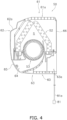
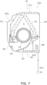
- the casing 60 is a substantially rectangular parallelepiped housing that houses the indoor heat exchanger 52, the indoor fan 53, the indoor expansion valve 54, the sensors 82 and 83, and the indoor-unit control unit 57. As illustrated in Fig. 3 and Fig. 4 , the casing 60 houses the indoor heat exchanger 52 in a position such that the indoor heat exchanger 52 has a substantially inversely V-shaped cross section when viewed in side elevation, and houses the indoor fan 53, which is a cross flow fan, in such a manner that the axial direction of the indoor fan 53 corresponds to the left-right direction.
- the casing 60 has a top surface 61 that forms an upper edge of the casing 60, a front panel 62 that forms a front portion of the casing 60, the bottom surface 63 that forms a bottom portion of the casing 60, a blow-out port 64, a louver 65, left and right side surfaces (not illustrated), and so on.
- the casing 60 is secured to the wall surface of the room R through a mounting plate 66, which is disposed on the back surface side of the casing 60.
- the top surface 61 has a plurality of top-surface suction ports 61a that open in the up-down direction.
- the front panel 62 is a panel that extends downward from near the front-side edge of the top surface 61.
- the front panel 62 has disposed in an upper portion thereof a front suction port 62a that is a long and narrow opening elongated in the left-right direction.
- the air in the room R passes through the top-surface suction ports 61a and the front suction port 62a and is taken into an air flow path S that is a space in the casing 60 where the indoor heat exchanger 52 and the indoor fan 53 are contained.
- the bottom surface 63 extends substantially horizontally below the indoor heat exchanger 52 and the indoor fan 53.
- the bottom surface 63 has an opening 63a through which the communication line 81a connecting the refrigerant gas sensor 81 and the indoor-unit control unit 57 is allowed to extend in the up-down direction.
- the blow-out port 64 is disposed in a front lower portion of the casing 60, which is located in a lower portion of the front panel 62 and at the front of the bottom surface 63, in such a manner as to open forward and downward.
- the blow-out port 64 is a long and narrow opening elongated in the left-right direction.
- the blow-out port 64 communicates with the top-surface suction ports 61a and the front suction port 62a through the air flow path S, which is a space where the indoor heat exchanger 52 and the indoor fan 53 are contained.
- the refrigerant gas sensor 81 described above is arranged such that conditioned air F flowing through the air flow path S and the blow-out port 64 in the casing 60 is not brought into direct contact with the refrigerant gas sensor 81. Specifically, the air conditioned in the indoor unit 50 flows forward and downward through the blow-out port 64 in the casing 60, whereas the refrigerant gas sensor 81 is secured in a position not included in an area through which the conditioned air F flows.
- the refrigerant gas sensor 81 is disposed at a position in an area ranging from 30 mm to 300 mm below the bottom surface 63 of the casing 60 and is secured to the side surface of the room R.
- the remote control 50a is an input device used by the user of the indoor unit 50 to input various instructions to switch the operating state of the air conditioner 100.
- the remote control 50a also functions as an output device for informing the user of the operating state of the air conditioner 100 or providing a predetermined notification.
- the remote control 50a and the indoor-unit control unit 57 are connected via a communication line and transmit and receive signals to and from each other.
- the remote control 50a has a built-in speaker.
- the outdoor-unit control unit 20 and the indoor-unit control unit 57 which are connected via a communication line, form the controller 70 that controls the operation of the air conditioner 100.
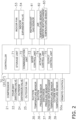
- Fig. 2 is a block diagram schematically illustrating the general configuration of the controller 70 and components connected to the controller 70.
- the controller 70 has a plurality of control modes, and controls the operation of the air conditioner 100 in accordance with the control modes.
- the controller 70 has, as the control modes, a normal operation mode, which is executed under normal conditions, and a refrigerant leak control mode, which is executed when a refrigerant leak occurs.
- the controller 70 is electrically connected to the actuators included in the outdoor unit 2 (specifically, the compressor 21 (the compressor motor M21), the outdoor expansion valve 24, and the outdoor fan 25 (the outdoor fan motor M25)) and the various sensors included in the outdoor unit 2 (such as the suction temperature sensor 35, the suction pressure sensor 36, the discharge pressure sensor 37, the outdoor heat-exchange temperature sensor 38, and the outside air temperature sensor 39).
- the controller 70 is also electrically connected to the actuators included in the indoor unit 50 (specifically, the indoor fan 53 (the indoor fan motor M53) and the indoor expansion valve 54). Further, the controller 70 is electrically connected to the refrigerant gas sensor 81, the air temperature sensor 82, the indoor heat-exchange temperature sensor 83, and the remote control 50a.
- the refrigerant gas sensor 81 is connected to the indoor-unit control unit 57 via the communication line 81a and is thus connected to the controller 70.
- the controller 70 mainly includes a storage unit 71, a communication unit 72, a mode control unit 73, an actuator control unit 74, and an output control unit 75. These components in the controller 70 are implemented by the integrated functioning of the components included in the outdoor-unit control unit 20 and/or the indoor-unit control unit 57.
- the storage unit 71 is constituted by, for example, a ROM, a RAM, a flash memory, and so on and includes a volatile storage area and a non-volatile storage area.
- the storage unit 71 stores a control program that defines processes performed by the components of the controller 70.
- the storage unit 71 further stores predetermined information (such as values detected by sensors and commands input to the remote control 50a) in predetermined storage areas, as appropriate, by using the components of the controller 70.
- the communication unit 72 is a function unit that serves as a communication interface for transmitting and receiving signals to and from devices connected to the controller 70.
- the communication unit 72 transmits a predetermined signal to a designated actuator upon receipt of a request from the actuator control unit 74. Further, upon receipt of a signal output from each of the sensors 35 to 39 and 81 to 83 and the remote control 50a, the communication unit 72 stores the signal in a predetermined storage area of the storage unit 71.
- the mode control unit 73 is a function unit that performs processing such as switching between the control modes. When a predetermined refrigerant leak condition is not satisfied for indoor unit 50, the mode control unit 73 sets the control mode to the normal operation mode.
- the mode control unit 73 switches the control mode to the refrigerant leak control mode.
- the actuator control unit 74 controls the operation of the actuators (such as the compressor 21) included in the air conditioner 100 in accordance with the control program.
- the actuator control unit 74 controls the number of revolutions of the compressor 21, the numbers of revolutions of the outdoor fan 25 and the indoor fan 53, the valve opening degree of the outdoor expansion valve 24, the valve opening degree of the indoor expansion valve 54, and the like in real time in accordance with a set temperature, values detected by various sensors, and so on.
- the actuator control unit 74 controls the operation of the actuators so that a predetermined operation can be performed. Specifically, when refrigerant leaks, the actuator control unit 74 interrupts the supply of refrigerant to the indoor unit 50.
- the output control unit 75 is a function unit that controls the operation of the remote control 50a, which serves as a display device.
- the output control unit 75 causes the remote control 50a to output predetermined information so as to present information related to the operating state or conditions to an administrator.
- the output control unit 75 causes the remote control 50a to display various kinds of information such as a set temperature.
- the output control unit 75 causes a display of the remote control 50a to display information indicating the occurrence of a refrigerant leak. Further, the output control unit 75 provides an audible notification indicating the occurrence of a refrigerant leak by using the built-in speaker of the remote control 50a. The output control unit 75 further causes the remote control 50a to display information to promote notification to a service engineer.
- the normal operation mode includes a cooling operation mode and a heating operation mode.
- the controller 70 determines and performs the cooling operation mode or the heating operation mode in accordance with an instruction received from the remote control 50a or the like.
- the connection state of the four-way switching valve 22 is set to a cooling-operation connection state in which the suction side of the compressor 21 and the gas-side shutoff valve 30 are connected while the discharge side of the compressor 21 and the outdoor heat exchanger 23 are connected.
- the refrigerant with which the refrigerant circuit 10 is filled is mainly circulated in the order of the compressor 21, the outdoor heat exchanger 23, the outdoor expansion valve 24, the indoor expansion valve 54, and the indoor heat exchanger 52.
- the refrigerant circuit 10 when the cooling operation mode is started, in the refrigerant circuit 10, the refrigerant is sucked into the compressor 21, compressed, and then discharged.
- a low pressure in the refrigeration cycle corresponds to a suction pressure detected by the suction pressure sensor 36
- a high pressure in the refrigeration cycle corresponds to a discharge pressure detected by the discharge pressure sensor 37.
- capacity control is performed in accordance with cooling load required for the indoor unit 50. Specifically, a target value of the suction pressure is set in accordance with the cooling load required for the indoor unit 50, and the operating frequency of the compressor 21 is controlled such that the suction pressure becomes equal to the target value.
- the gas refrigerant discharged from the compressor 21 travels through the discharge pipe 31 and the four-way switching valve 22, and flows into the gas-side end of the outdoor heat exchanger 23.
- the gas refrigerant that has flowed into the gas-side end of the outdoor heat exchanger 23 releases heat and condenses into a liquid refrigerant in the outdoor heat exchanger 23 by exchanging heat with outdoor-side air supplied by the outdoor fan 25.
- the liquid refrigerant flows out of the liquid-side end of the outdoor heat exchanger 23.
- the liquid refrigerant that has flowed out of the liquid-side end of the outdoor heat exchanger 23 travels through the outdoor liquid-side pipe 32, the outdoor expansion valve 24, the liquid-side shutoff valve 29, and the liquid-refrigerant connection pipe 6, and flows into the indoor unit 50.
- the outdoor expansion valve 24 is controlled to be fully opened.
- the refrigerant that has flowed into the indoor unit 50 travels through a portion of the indoor liquid refrigerant pipe 58, and flows into the indoor expansion valve 54.
- the refrigerant that has flowed into the indoor expansion valve 54 is decompressed by the indoor expansion valve 54 until the refrigerant becomes a low-pressure refrigerant in the refrigeration cycle, and then flows into the liquid-side end of the indoor heat exchanger 52.
- the valve opening degree of the indoor expansion valve 54 is controlled such that the degree of superheating of refrigerant sucked into the compressor 21 becomes equal to a predetermined degree of superheating.
- the degree of superheating of refrigerant sucked into the compressor 21 is calculated by the controller 70 by using the temperature detected by the suction temperature sensor 35 and the pressure detected by the suction pressure sensor 36.
- the refrigerant that has flowed into the liquid-side end of the indoor heat exchanger 52 evaporates into a gas refrigerant in the indoor heat exchanger 52 by exchanging heat with indoor air supplied by the indoor fan 53.
- the gas refrigerant flows out of the gas-side end of the indoor heat exchanger 52.
- the gas refrigerant that has flowed out of the gas-side end of the indoor heat exchanger 52 flows to the gas-refrigerant connection pipe 7 through the indoor gas refrigerant pipe 59.
- the refrigerant flowing through the gas-refrigerant connection pipe 7 travels through the gas-side shutoff valve 30, the outdoor gas-side pipe 33, the four-way switching valve 22, and the suction pipe 34, and is again sucked into the compressor 21.
- connection state of the four-way switching valve 22 is set to a heating-operation connection state in which the suction side of the compressor 21 and the outdoor heat exchanger 23 are connected while the discharge side of the compressor 21 and the gas-side shutoff valve 30 are connected.
- the refrigerant with which the refrigerant circuit 10 is filled is mainly circulated in the order of the compressor 21, the indoor heat exchanger 52, the indoor expansion valve 54, the outdoor expansion valve 24, and the outdoor heat exchanger 23.
- the refrigerant circuit 10 when the heating operation mode is started, in the refrigerant circuit 10, the refrigerant is sucked into the compressor 21, compressed, and then discharged.
- a low pressure in the refrigeration cycle corresponds to a suction pressure detected by the suction pressure sensor 36
- a high pressure in the refrigeration cycle corresponds to a discharge pressure detected by the discharge pressure sensor 37.
- capacity control is performed in accordance with the heating load required for the indoor unit 50. Specifically, a target value of the discharge pressure is set in accordance with the heating load required for the indoor unit 50, and the operating frequency of the compressor 21 is controlled such that the discharge pressure becomes equal to the target value.
- the gas refrigerant discharged from the compressor 21 flows through the discharge pipe 31, the four-way switching valve 22, the outdoor gas-side pipe 33, and the gas-refrigerant connection pipe 7, and then flows into the indoor unit 50 through the indoor gas refrigerant pipe 59.
- the refrigerant that has flowed into the indoor unit 50 travels through the indoor gas refrigerant pipe 59, and flows into the gas-side end of the indoor heat exchanger 52.
- the refrigerant that has flowed into the gas-side end of the indoor heat exchanger 52 releases heat and condenses into a liquid refrigerant in the indoor heat exchanger 52 by exchanging heat with indoor air supplied by the indoor fan 53.
- the liquid refrigerant flows out of the liquid-side end of the indoor heat exchanger 52.
- the refrigerant that has flowed out of the liquid-side end of the indoor heat exchanger 52 flows to the liquid-refrigerant connection pipe 6 through the indoor liquid refrigerant pipe 58 and the indoor expansion valve 54.
- the valve opening degree of the indoor expansion valve 54 is controlled to be fully opened.
- the refrigerant flowing through the liquid-refrigerant connection pipe 6 flows into the outdoor expansion valve 24 through the liquid-side shutoff valve 29 and the outdoor liquid-side pipe 32.
- the refrigerant that has flowed into the outdoor expansion valve 24 is decompressed until the refrigerant becomes a low-pressure refrigerant in the refrigeration cycle, and then flows into the liquid-side end of the outdoor heat exchanger 23.
- the valve opening degree of the outdoor expansion valve 24 is controlled such that the degree of superheating of refrigerant sucked into the compressor 21 becomes equal to a predetermined degree of superheating.
- the refrigerant that has flowed into the liquid-side end of the outdoor heat exchanger 23 evaporates into a gas refrigerant in the outdoor heat exchanger 23 by exchanging heat with outdoor air supplied by the outdoor fan 25.
- the gas refrigerant flows out of the gas-side end of the outdoor heat exchanger 23.
- the refrigerant that has flowed out of the gas-side end of the outdoor heat exchanger 23 travels through the four-way switching valve 22 and the suction pipe 34, and is again sucked into the compressor 21.
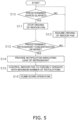
- the following describes an example process flow for the refrigerant leak control mode, which is executed by the controller 70 when a refrigerant leak occurs in the normal operation mode with reference to a flowchart illustrated in Fig. 5 .
- step S 10 when the normal operation mode of the cooling operation mode or heating operation mode is being executed, the controller 70 determines whether a predetermined period has elapsed since the start of a cooling or heating operation or since the latest detection of the leaking refrigerant gas concentration. If it is determined that the predetermined period has elapsed, the process proceeds to step S11. If it is determined that the predetermined period has not elapsed, step S10 is repeatedly performed.
- step S11 the controller 70 temporarily stops the driving of the indoor fan 53 to reduce the air flow in the room R.
- step S12 the controller 70 determines whether the refrigerant concentration detected by the refrigerant gas sensor 81 is greater than or equal to a predetermined refrigerant concentration.
- the predetermined refrigerant concentration is determined in advance in accordance with the type of the refrigerant charged in the refrigerant circuit 10 (in this embodiment, R32) and is stored in the storage unit 71. If the controller 70 determines that the refrigerant concentration detected by the refrigerant gas sensor 81 is greater than or equal to the predetermined refrigerant concentration, the process proceeds to step S14. On the other hand, if the refrigerant concentration detected by the refrigerant gas sensor 81 is less than the predetermined refrigerant concentration, the process proceeds to step S13.
- step S13 the controller 70 resumes the driving of the indoor fan 53, which has been stopped, and returns to step S10, with the normal operation mode remaining continuously active.
- step S14 the controller 70 starts the refrigerant leak control mode and causes the output control unit 75 to display, on the display of the remote control 50a, information indicating a leak of refrigerant as text information. Further, the controller 70 causes the output control unit 75 to provide a notification indicating the leak of refrigerant as audio information from the speaker of the remote control 50a.
- step S15 the controller 70 controls the indoor fan 53 to forcibly operate with a maximum number of revolutions. This allows the refrigerant that has leaked to be stirred and can suppress a local increase in concentration.
- step S16 a pump-down operation is performed.
- the pump-down operation while the connection state of the four-way switching valve 22 is set to the connection state in the cooling operation mode, the outdoor expansion valve 24 is closed, the compressor 21 is driven, the outdoor fan 25 is driven, and the outdoor heat exchanger 23 is caused to function as a condenser for refrigerant. Accordingly, within the refrigerant circuit 10, refrigerant present on the indoor unit 50 side is collected before the refrigerant reaches the outdoor expansion valve 24 from the discharge side of the compressor 21 of the outdoor unit 2 through the outdoor heat exchanger 23, thereby suppressing a further leak of refrigerant from a leak portion of the indoor unit 50.
- the pump-down operation is performed, with the connection state of the four-way switching valve 22 remaining unchanged.
- the pump-down operation is performed after the connection state of the four-way switching valve 22 is switched to that in the cooling operation mode.
- the pump-down operation is finished when the pressure detected by the suction pressure sensor 36 becomes less than or equal to a predetermined termination pressure. The driving of the compressor 21 is stopped, and the operation of the air conditioner 100 is stopped.
- the refrigerant gas sensor 81 is disposed in a position not included in an area through which the conditioned air F flows. This can prevent the refrigerant gas sensor 81 from coming into direct contact with the conditioned air flow, and thus can prevent condensation from forming on the refrigerant gas sensor 81 itself. Accordingly, the detection accuracy of the refrigerant gas sensor 81 can be enhanced.
- the refrigerant gas sensor 81 is arranged in an area below the bottom surface 63 of the casing 60 of the indoor unit 50, and, even when the normal operation mode is being executed, the refrigerant gas sensor 81 performs detection, with the air flow in the room R kept reduced while the driving of the indoor fan 53 is stopped.
- R32 which is a refrigerant having a greater specific gravity than air and with which the refrigerant circuit 10 of the air conditioner 100 is filled, is not introduced into the conditioned air flow F and is likely to gather, when leaking, in an area below, rather than above, the casing 60 of the indoor unit 50 due to its weight.
- the refrigerant gas sensor 81 which is disposed in an area below the bottom surface 63, can thus more reliably detect a refrigerant leak.
- the indoor fan 53 is forcibly driven with a maximum number of revolutions. This can suppress the occurrence of a local increase in refrigerant concentration within a room.
- the refrigerant to be charged in the refrigerant circuit 10 is not limited to this, and examples of the refrigerant other than R32 may include flammable refrigerants classified in Class A3 of ASHRAE 34 Refrigerant Safety Classification, low flammable refrigerants classified in Class A2 of ASHRAE 34 Refrigerant Safety Classification, mildly flammable refrigerants classified in Class A2L of ASHRAE 34 Refrigerant Safety Classification, and highly toxic refrigerants classified in Class B of ASHRAE 34 Refrigerant Safety Classification.
- refrigerant to be charged in the refrigerant circuit 10, other than R32 may include refrigerants with lower GWP than R32 (a natural refrigerant such as R717 and, R170, R1270, R290, R600, R600a, R152a, and a refrigerant mixture thereof).
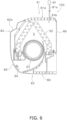
- the top surface 61 has an opening 61b through which the communication line 81a is allowed to extend, and the refrigerant gas sensor 81 is arranged and secured in a space above the top surface 61.
- a refrigerant e.g., a natural refrigerant such as R717
- the refrigerant gas sensor 81 is arranged and secured in a space above the top surface 61.
- the controller 70 may be configured to be capable of determining a detection signal from the refrigerant gas sensor 81 even while the driving of the air conditioner 100 is stopped and capable of detecting a refrigerant leak even during stopped operation.
- the air conditioner 100 is stopped, as in the case where the indoor fan 53 is temporarily stopped when the normal operation mode is being executed according to the embodiment described above, the air flow in the room R is kept reduced, resulting in accurate detection.
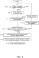
- a sensor raising and lowering mechanism 88 may be included to allow the refrigerant gas sensor 81 to move in the up-down direction.
- the sensor raising and lowering mechanism 88 is electrically connected to the indoor-unit control unit 57. With the configuration illustrated in Fig. 8 , the driving of the sensor raising and lowering mechanism 88 is controlled by the actuator control unit 74 of the controller 70. Specifically, to raise the refrigerant gas sensor 81, which has been lowered, the sensor raising and lowering mechanism 88 is driven to hoist the communication line 81a up and raise the refrigerant gas sensor 81 until the refrigerant gas sensor 81 is placed in an accommodation position 81b at the bottom surface 63.
- the sensor raising and lowering mechanism 88 is driven to loose the communication line 81a and lower the refrigerant gas sensor 81 to a predetermined position 30 mm or more and 300 mm or less below the bottom surface 63.
- a process for raising and lowering the refrigerant gas sensor 81 for use is also performed by, as in the embodiment described above, as illustrated in Fig. 9 , executing step Sllx between steps S11 and S12 according to the embodiment described above to lower the refrigerant gas sensor 81, and executing step S12x between step S12 and step S13 to raise the refrigerant gas sensor 81. Accordingly, effects similar to those of the embodiment described above can be achieved. Since the refrigerant gas sensor 81 can be accommodated, a neat appearance can be obtained.
- the type of notification is not limited to these.
- the lamp may be turned on or made to blink.
- the notification may be provided in a different way by changing the amount of emission of light, the blinking speed, or the like such that illumination for which a normal condition without a refrigerant leak is determined is different from illumination for which it is determined that refrigerant has leaked.
- the controller 70 When the controller 70 is connected to an external remote monitoring device or the like, which is constituted by a computer, via the communication unit 72 so that they can communicate with each other over a communication network, the controller 70 may transmit information indicating that refrigerant has leaked to the external remote monitoring device or the like. In this case, a service engineer who specializes in taking countermeasures against refrigerant leaks that are being monitored in the remote monitoring device can also be appropriately informed of the situation.
- control of the air conditioner 100 in the refrigerant leak control mode is not limited to this.
- control may be performed to reduce the frequency of the compressor 21, compared to the current situation, after a leak. If refrigerant leaks during the execution of the cooling operation mode, the indoor expansion valve 54 may be closed so as not to supply further refrigerant to the indoor heat exchanger 52.
- the air conditioner 100 has been described as an example in which the indoor unit 50 and the outdoor unit 2 are separately arranged in remote locations.
- an air conditioner may be configured such that the internal components of the indoor unit 50 and the internal components of the outdoor unit 2 according to the embodiment described above are housed in a single housing, and may be used in such a manner that the single housing is mounted over the indoor side and the outdoor side.
- a controller of ventilation equipment which is installed in the building separately from the air conditioner 100, and the controller 70 of the air conditioner 100 are configured to be capable of communicating with each other, and, when the indoor fan 53 is caused to forcibly operate if refrigerant leaks, a fan included in the ventilation equipment may also be caused to forcibly operate at the same time.
Landscapes
- Engineering & Computer Science (AREA)
- Mechanical Engineering (AREA)
- General Engineering & Computer Science (AREA)
- Chemical & Material Sciences (AREA)
- Combustion & Propulsion (AREA)
- Physics & Mathematics (AREA)
- Thermal Sciences (AREA)
- Air Conditioning Control Device (AREA)
- Air Filters, Heat-Exchange Apparatuses, And Housings Of Air-Conditioning Units (AREA)
Claims (5)
- Innenraumeinheit (50, 150, 250) für eine Kühlvorrichtung (100) einschließlich eines Kühlmittelkreislaufs (10), in den ein Kühlmittel eingefüllt ist und der einen Kühlkreislauf durchführt, wobei die Innenraumeinheit für die Kühlvorrichtung umfasst:ein Gehäuse (60), in dem zumindest ein Teil des Kühlmittelkreislaufs untergebracht ist, wobei das Gehäuse eine Ausblasöffnung (64) aufweist, die sich in eine andere Richtung als eine Aufwärts-Abwärts-Richtung öffnet;ein Gebläse (53), das in dem Gehäuse untergebracht ist und das einen Luftstrom erzeugt, der von der Ausblasöffnung nach außerhalb des Gehäuses gerichtet ist; undeinen Kühlmittelgassensor (81), der in der Lage ist, ein Kühlmittelgas unterhalb einer unteren Fläche (63) des Gehäuses oder oberhalb einer oberen Fläche (61) des Gehäuses zu detektieren, wobeider Kühlmittelgassensor ein Kühlmittelgas in einem Bereich von 30 mm bis 300 mm unterhalb der unteren Fläche des Gehäuses detektiert, unddas Gehäuse geeignet ist, um an einer Wandfläche eines Raumes befestigt zu werden, dadurch gekennzeichnet, dass die Innenraumeinheit für die Kühlvorrichtung weiter umfasst:
eine Steuereinheit (70), die so konfiguriert ist, dass sie den Kühlmittelgassensor veranlasst, ein Kühlmittelgas zu detektieren, während sie den Antrieb des Gebläses stoppt. - Innenraumeinheit für die Kühlvorrichtung nach Anspruch 1, wobei
das in den Kühlmittelkreislauf eingefüllte Kühlmittel ein Einkomponenten-Kühlmittel ist, das eines von einem entflammbaren Kühlmittel, einem schwer entflammbaren Kühlmittel, einem leicht entflammbaren Kühlmittel und einem hochtoxischen Kühlmittel oder ein Kühlmittelgemisch von zwei oder mehr davon ist. - Innenraumeinheit für die Kühlvorrichtung nach Anspruch 1, wobei
das in den Kühlmittelkreislauf eingefüllte Kühlmittel R32 oder ein Kühlmittel mit niedrigerem GWP als R32 ist. - Innenraumeinheit (50) der Kühlvorrichtung nach Anspruch 1, wobei
der Kühlmittelgassensor geeignet ist, in einem Bereich von 30 mm bis 300 mm unterhalb der unteren Fläche des Gehäuses befestigt zu werden. - Innenraumeinheit (250) der Kühlvorrichtung nach Anspruch 1, weiter umfassendeinen Hebe- und Senkmechanismus (88), der es dem Kühlmittelgassensor ermöglicht, sich von der unteren Fläche des Gehäuses nach unten und in das Gehäuse zu bewegen, wobeidie Steuereinheit den Hebe- und Senkmechanismus veranlasst, den Kühlmittelgassensor auf eine Position 30 mm oder mehr und 300 mm oder weniger unterhalb der unteren Fläche des Gehäuses abzusenken, während der Antrieb des Gebläses gestoppt wird, und den Kühlmittelgassensor veranlasst, ein Kühlmittelgas zu detektieren.
Priority Applications (1)
| Application Number | Priority Date | Filing Date | Title |
|---|---|---|---|
| EP24188188.7A EP4421392A3 (de) | 2017-03-31 | 2018-03-28 | Innenraumeinheit einer kühlvorrichtung |
Applications Claiming Priority (2)
| Application Number | Priority Date | Filing Date | Title |
|---|---|---|---|
| JP2017072645A JP6555293B2 (ja) | 2017-03-31 | 2017-03-31 | 冷凍装置の室内ユニット |
| PCT/JP2018/012959 WO2018181567A1 (ja) | 2017-03-31 | 2018-03-28 | 冷凍装置の室内ユニット |
Related Child Applications (2)
| Application Number | Title | Priority Date | Filing Date |
|---|---|---|---|
| EP24188188.7A Division-Into EP4421392A3 (de) | 2017-03-31 | 2018-03-28 | Innenraumeinheit einer kühlvorrichtung |
| EP24188188.7A Division EP4421392A3 (de) | 2017-03-31 | 2018-03-28 | Innenraumeinheit einer kühlvorrichtung |
Publications (3)
| Publication Number | Publication Date |
|---|---|
| EP3604982A1 EP3604982A1 (de) | 2020-02-05 |
| EP3604982A4 EP3604982A4 (de) | 2020-11-25 |
| EP3604982B1 true EP3604982B1 (de) | 2024-08-21 |
Family
ID=63677892
Family Applications (2)
| Application Number | Title | Priority Date | Filing Date |
|---|---|---|---|
| EP24188188.7A Pending EP4421392A3 (de) | 2017-03-31 | 2018-03-28 | Innenraumeinheit einer kühlvorrichtung |
| EP18777191.0A Active EP3604982B1 (de) | 2017-03-31 | 2018-03-28 | Innenraumeinheit einer kühlvorrichtung |
Family Applications Before (1)
| Application Number | Title | Priority Date | Filing Date |
|---|---|---|---|
| EP24188188.7A Pending EP4421392A3 (de) | 2017-03-31 | 2018-03-28 | Innenraumeinheit einer kühlvorrichtung |
Country Status (5)
| Country | Link |
|---|---|
| US (1) | US11131470B2 (de) |
| EP (2) | EP4421392A3 (de) |
| JP (1) | JP6555293B2 (de) |
| CN (1) | CN110402360B (de) |
| WO (1) | WO2018181567A1 (de) |
Families Citing this family (18)
| Publication number | Priority date | Publication date | Assignee | Title |
|---|---|---|---|---|
| US10119738B2 (en) | 2014-09-26 | 2018-11-06 | Waterfurnace International Inc. | Air conditioning system with vapor injection compressor |
| US10871314B2 (en) | 2016-07-08 | 2020-12-22 | Climate Master, Inc. | Heat pump and water heater |
| US10866002B2 (en) | 2016-11-09 | 2020-12-15 | Climate Master, Inc. | Hybrid heat pump with improved dehumidification |
| US11592215B2 (en) | 2018-08-29 | 2023-02-28 | Waterfurnace International, Inc. | Integrated demand water heating using a capacity modulated heat pump with desuperheater |
| JP6991369B2 (ja) * | 2019-01-09 | 2022-01-12 | 三菱電機株式会社 | 空気調和装置 |
| EP3760955B1 (de) | 2019-07-02 | 2024-09-18 | Carrier Corporation | Verteiltes gefahrendetektionssystem für ein transportkühlsystem |
| CA3081986A1 (en) | 2019-07-15 | 2021-01-15 | Climate Master, Inc. | Air conditioning system with capacity control and controlled hot water generation |
| US11231198B2 (en) | 2019-09-05 | 2022-01-25 | Trane International Inc. | Systems and methods for refrigerant leak detection in a climate control system |
| US11326797B2 (en) * | 2020-04-14 | 2022-05-10 | Haier Us Appliance Solutions, Inc. | Gas sensing system for an air conditioner unit |
| JP2021173435A (ja) * | 2020-04-21 | 2021-11-01 | 三菱電機株式会社 | 冷凍サイクル装置 |
| WO2021229647A1 (ja) * | 2020-05-11 | 2021-11-18 | 三菱電機株式会社 | 冷凍サイクル装置 |
| EP3974735A1 (de) * | 2020-09-25 | 2022-03-30 | Daikin Industries, Ltd. | Innenraumeinheit einer wärmepumpe |
| CN114623588A (zh) * | 2020-12-09 | 2022-06-14 | 广东美的制冷设备有限公司 | 空调室内机和空调器 |
| US12181189B2 (en) | 2021-11-10 | 2024-12-31 | Climate Master, Inc. | Ceiling-mountable heat pump system |
| US12487008B2 (en) | 2022-01-14 | 2025-12-02 | Trane International Inc. | Method of commissioning an HVAC system |
| US12117191B2 (en) | 2022-06-24 | 2024-10-15 | Trane International Inc. | Climate control system with improved leak detector |
| JP2024164488A (ja) * | 2023-05-15 | 2024-11-27 | パナソニックIpマネジメント株式会社 | 空気調和機 |
| JP7674419B2 (ja) * | 2023-06-23 | 2025-05-09 | 日立ジョンソンコントロールズ空調株式会社 | 空気調和機及び空気調和システム |
Family Cites Families (18)
| Publication number | Priority date | Publication date | Assignee | Title |
|---|---|---|---|---|
| JPH06180166A (ja) * | 1992-12-09 | 1994-06-28 | Toshiba Corp | 空気調和機 |
| JPH09318208A (ja) * | 1996-06-03 | 1997-12-12 | Daikin Ind Ltd | 可燃性冷媒を用いた冷凍装置 |
| JP4386544B2 (ja) * | 2000-05-26 | 2009-12-16 | 三洋電機株式会社 | 空気調和機 |
| CN1161570C (zh) * | 2000-09-26 | 2004-08-11 | 大金工业株式会社 | 空调机 |
| JP2002195718A (ja) | 2000-12-28 | 2002-07-10 | Nakano Refrigerators Co Ltd | ショーケース等の集中管理装置 |
| JP2005016822A (ja) * | 2003-06-25 | 2005-01-20 | Toshiba Kyaria Kk | 可燃性冷媒空気調和機の冷媒漏洩検知装置 |
| WO2010062923A1 (en) * | 2008-11-26 | 2010-06-03 | Delphi Technologies, Inc. | Refrigerant leak detection system |
| JP2011202831A (ja) * | 2010-03-25 | 2011-10-13 | Hitachi Appliances Inc | リモートコントローラ及び室内ユニット並びに空気調和機 |
| JP5818849B2 (ja) * | 2013-08-26 | 2015-11-18 | 三菱電機株式会社 | 空気調和装置および冷媒漏洩検知方法 |
| JP5812081B2 (ja) * | 2013-11-12 | 2015-11-11 | ダイキン工業株式会社 | 室内機 |
| JP5983707B2 (ja) | 2014-10-31 | 2016-09-06 | ダイキン工業株式会社 | 空気調和機の室内機 |
| JP6431339B2 (ja) * | 2014-11-07 | 2018-11-28 | 日立ジョンソンコントロールズ空調株式会社 | 室内機、および、それを備える空気調和機 |
| JP6466219B2 (ja) * | 2015-03-20 | 2019-02-06 | 日立ジョンソンコントロールズ空調株式会社 | 空気調和機の室内機 |
| JP6135705B2 (ja) * | 2015-04-06 | 2017-05-31 | ダイキン工業株式会社 | 利用側空調装置 |
| JP6572628B2 (ja) * | 2015-05-27 | 2019-09-11 | ダイキン工業株式会社 | 空調換気システム |
| GB2554267B (en) | 2015-06-30 | 2020-12-16 | Mitsubishi Electric Corp | Refrigerant leakage detection system |
| JP6176304B2 (ja) * | 2015-10-29 | 2017-08-09 | 三菱電機株式会社 | コンセント、そのカバープレート及び冷媒検知装置、並びに、コンセント又は冷媒検知装置を備えた環境監視システム |
| CN205664530U (zh) * | 2016-05-26 | 2016-10-26 | 福建龙峰纺织科技实业有限公司 | 一种纺织车间的空调传感器支架 |
-
2017
- 2017-03-31 JP JP2017072645A patent/JP6555293B2/ja active Active
-
2018
- 2018-03-28 EP EP24188188.7A patent/EP4421392A3/de active Pending
- 2018-03-28 CN CN201880012641.5A patent/CN110402360B/zh active Active
- 2018-03-28 WO PCT/JP2018/012959 patent/WO2018181567A1/ja not_active Ceased
- 2018-03-28 US US16/492,982 patent/US11131470B2/en active Active
- 2018-03-28 EP EP18777191.0A patent/EP3604982B1/de active Active
Also Published As
| Publication number | Publication date |
|---|---|
| CN110402360A (zh) | 2019-11-01 |
| US11131470B2 (en) | 2021-09-28 |
| JP2018173249A (ja) | 2018-11-08 |
| US20200018504A1 (en) | 2020-01-16 |
| EP3604982A4 (de) | 2020-11-25 |
| JP6555293B2 (ja) | 2019-08-07 |
| EP4421392A2 (de) | 2024-08-28 |
| EP3604982A1 (de) | 2020-02-05 |
| CN110402360B (zh) | 2021-04-30 |
| EP4421392A3 (de) | 2024-10-30 |
| WO2018181567A1 (ja) | 2018-10-04 |
Similar Documents
| Publication | Publication Date | Title |
|---|---|---|
| EP3604982B1 (de) | Innenraumeinheit einer kühlvorrichtung | |
| EP3604980B1 (de) | Kühlgerät | |
| US11041666B2 (en) | Refrigeration apparatus | |
| EP3683524B1 (de) | Kühlvorrichtung | |
| EP3418655B1 (de) | Kühlvorrichtung | |
| EP3026371B1 (de) | Kältekreislaufvorrichtung | |
| JP6498289B2 (ja) | 冷凍サイクルシステム | |
| EP3581855B1 (de) | Klimatisierungsvorrichtung | |
| EP3064847A1 (de) | Klimaanlagenvorrichtung | |
| US10859299B2 (en) | Air-conditioning apparatus and refrigerant leakage detection method | |
| EP3306237B1 (de) | Kältekreislaufvorrichtung und verfahren zur erkennung von kältemittellecks | |
| EP4067776A1 (de) | Klimatisierungssystem | |
| JP2016011767A (ja) | 空調室内機 | |
| JP2019039599A (ja) | 空気調和装置 | |
| JP2022006650A (ja) | 空気調和機 | |
| JP7187898B2 (ja) | 冷凍サイクル装置 | |
| CN115540074A (zh) | 移动空调器及其控制方法 | |
| JP7490841B1 (ja) | 空気調和装置 | |
| EP3882536A1 (de) | Klimaanlage | |
| JP2020034249A (ja) | 冷凍サイクル装置 | |
| KR20190000584A (ko) | 공기 조화기 |
Legal Events
| Date | Code | Title | Description |
|---|---|---|---|
| STAA | Information on the status of an ep patent application or granted ep patent |
Free format text: STATUS: THE INTERNATIONAL PUBLICATION HAS BEEN MADE |
|
| PUAI | Public reference made under article 153(3) epc to a published international application that has entered the european phase |
Free format text: ORIGINAL CODE: 0009012 |
|
| STAA | Information on the status of an ep patent application or granted ep patent |
Free format text: STATUS: REQUEST FOR EXAMINATION WAS MADE |
|
| 17P | Request for examination filed |
Effective date: 20190822 |
|
| AK | Designated contracting states |
Kind code of ref document: A1 Designated state(s): AL AT BE BG CH CY CZ DE DK EE ES FI FR GB GR HR HU IE IS IT LI LT LU LV MC MK MT NL NO PL PT RO RS SE SI SK SM TR |
|
| AX | Request for extension of the european patent |
Extension state: BA ME |
|
| DAV | Request for validation of the european patent (deleted) | ||
| DAX | Request for extension of the european patent (deleted) | ||
| A4 | Supplementary search report drawn up and despatched |
Effective date: 20201023 |
|
| RIC1 | Information provided on ipc code assigned before grant |
Ipc: F24F 11/49 20180101ALI20201020BHEP Ipc: F25B 49/00 20060101ALI20201020BHEP Ipc: F24F 11/36 20180101ALI20201020BHEP Ipc: F24F 1/0018 20190101ALI20201020BHEP Ipc: F24F 1/0011 20190101ALI20201020BHEP Ipc: F25B 49/02 20060101AFI20201020BHEP |
|
| STAA | Information on the status of an ep patent application or granted ep patent |
Free format text: STATUS: EXAMINATION IS IN PROGRESS |
|
| 17Q | First examination report despatched |
Effective date: 20220318 |
|
| RAP3 | Party data changed (applicant data changed or rights of an application transferred) |
Owner name: DAIKIN INDUSTRIES, LTD. |
|
| P01 | Opt-out of the competence of the unified patent court (upc) registered |
Effective date: 20230525 |
|
| GRAP | Despatch of communication of intention to grant a patent |
Free format text: ORIGINAL CODE: EPIDOSNIGR1 |
|
| STAA | Information on the status of an ep patent application or granted ep patent |
Free format text: STATUS: GRANT OF PATENT IS INTENDED |
|
| INTG | Intention to grant announced |
Effective date: 20240313 |
|
| GRAS | Grant fee paid |
Free format text: ORIGINAL CODE: EPIDOSNIGR3 |
|
| GRAA | (expected) grant |
Free format text: ORIGINAL CODE: 0009210 |
|
| STAA | Information on the status of an ep patent application or granted ep patent |
Free format text: STATUS: THE PATENT HAS BEEN GRANTED |
|
| AK | Designated contracting states |
Kind code of ref document: B1 Designated state(s): AL AT BE BG CH CY CZ DE DK EE ES FI FR GB GR HR HU IE IS IT LI LT LU LV MC MK MT NL NO PL PT RO RS SE SI SK SM TR |
|
| REG | Reference to a national code |
Ref country code: GB Ref legal event code: FG4D |
|
| REG | Reference to a national code |
Ref country code: CH Ref legal event code: EP |
|
| REG | Reference to a national code |
Ref country code: IE Ref legal event code: FG4D |
|
| REG | Reference to a national code |
Ref country code: DE Ref legal event code: R096 Ref document number: 602018073369 Country of ref document: DE |
|
| REG | Reference to a national code |
Ref country code: LT Ref legal event code: MG9D |
|
| REG | Reference to a national code |
Ref country code: NL Ref legal event code: MP Effective date: 20240821 |
|
| PG25 | Lapsed in a contracting state [announced via postgrant information from national office to epo] |
Ref country code: NO Free format text: LAPSE BECAUSE OF FAILURE TO SUBMIT A TRANSLATION OF THE DESCRIPTION OR TO PAY THE FEE WITHIN THE PRESCRIBED TIME-LIMIT Effective date: 20241121 |
|
| REG | Reference to a national code |
Ref country code: AT Ref legal event code: MK05 Ref document number: 1715845 Country of ref document: AT Kind code of ref document: T Effective date: 20240821 |
|
| PG25 | Lapsed in a contracting state [announced via postgrant information from national office to epo] |
Ref country code: NL Free format text: LAPSE BECAUSE OF FAILURE TO SUBMIT A TRANSLATION OF THE DESCRIPTION OR TO PAY THE FEE WITHIN THE PRESCRIBED TIME-LIMIT Effective date: 20240821 Ref country code: GR Free format text: LAPSE BECAUSE OF FAILURE TO SUBMIT A TRANSLATION OF THE DESCRIPTION OR TO PAY THE FEE WITHIN THE PRESCRIBED TIME-LIMIT Effective date: 20241122 Ref country code: FI Free format text: LAPSE BECAUSE OF FAILURE TO SUBMIT A TRANSLATION OF THE DESCRIPTION OR TO PAY THE FEE WITHIN THE PRESCRIBED TIME-LIMIT Effective date: 20240821 Ref country code: PT Free format text: LAPSE BECAUSE OF FAILURE TO SUBMIT A TRANSLATION OF THE DESCRIPTION OR TO PAY THE FEE WITHIN THE PRESCRIBED TIME-LIMIT Effective date: 20241223 Ref country code: PL Free format text: LAPSE BECAUSE OF FAILURE TO SUBMIT A TRANSLATION OF THE DESCRIPTION OR TO PAY THE FEE WITHIN THE PRESCRIBED TIME-LIMIT Effective date: 20240821 |
|
| PG25 | Lapsed in a contracting state [announced via postgrant information from national office to epo] |
Ref country code: BG Free format text: LAPSE BECAUSE OF FAILURE TO SUBMIT A TRANSLATION OF THE DESCRIPTION OR TO PAY THE FEE WITHIN THE PRESCRIBED TIME-LIMIT Effective date: 20240821 |
|
| PG25 | Lapsed in a contracting state [announced via postgrant information from national office to epo] |
Ref country code: LV Free format text: LAPSE BECAUSE OF FAILURE TO SUBMIT A TRANSLATION OF THE DESCRIPTION OR TO PAY THE FEE WITHIN THE PRESCRIBED TIME-LIMIT Effective date: 20240821 |
|
| PG25 | Lapsed in a contracting state [announced via postgrant information from national office to epo] |
Ref country code: AT Free format text: LAPSE BECAUSE OF FAILURE TO SUBMIT A TRANSLATION OF THE DESCRIPTION OR TO PAY THE FEE WITHIN THE PRESCRIBED TIME-LIMIT Effective date: 20240821 Ref country code: IS Free format text: LAPSE BECAUSE OF FAILURE TO SUBMIT A TRANSLATION OF THE DESCRIPTION OR TO PAY THE FEE WITHIN THE PRESCRIBED TIME-LIMIT Effective date: 20241221 |
|
| PG25 | Lapsed in a contracting state [announced via postgrant information from national office to epo] |
Ref country code: HR Free format text: LAPSE BECAUSE OF FAILURE TO SUBMIT A TRANSLATION OF THE DESCRIPTION OR TO PAY THE FEE WITHIN THE PRESCRIBED TIME-LIMIT Effective date: 20240821 |
|
| PG25 | Lapsed in a contracting state [announced via postgrant information from national office to epo] |
Ref country code: ES Free format text: LAPSE BECAUSE OF FAILURE TO SUBMIT A TRANSLATION OF THE DESCRIPTION OR TO PAY THE FEE WITHIN THE PRESCRIBED TIME-LIMIT Effective date: 20240821 Ref country code: RS Free format text: LAPSE BECAUSE OF FAILURE TO SUBMIT A TRANSLATION OF THE DESCRIPTION OR TO PAY THE FEE WITHIN THE PRESCRIBED TIME-LIMIT Effective date: 20241121 |
|
| PG25 | Lapsed in a contracting state [announced via postgrant information from national office to epo] |
Ref country code: RS Free format text: LAPSE BECAUSE OF FAILURE TO SUBMIT A TRANSLATION OF THE DESCRIPTION OR TO PAY THE FEE WITHIN THE PRESCRIBED TIME-LIMIT Effective date: 20241121 Ref country code: PT Free format text: LAPSE BECAUSE OF FAILURE TO SUBMIT A TRANSLATION OF THE DESCRIPTION OR TO PAY THE FEE WITHIN THE PRESCRIBED TIME-LIMIT Effective date: 20241223 Ref country code: PL Free format text: LAPSE BECAUSE OF FAILURE TO SUBMIT A TRANSLATION OF THE DESCRIPTION OR TO PAY THE FEE WITHIN THE PRESCRIBED TIME-LIMIT Effective date: 20240821 Ref country code: NO Free format text: LAPSE BECAUSE OF FAILURE TO SUBMIT A TRANSLATION OF THE DESCRIPTION OR TO PAY THE FEE WITHIN THE PRESCRIBED TIME-LIMIT Effective date: 20241121 Ref country code: NL Free format text: LAPSE BECAUSE OF FAILURE TO SUBMIT A TRANSLATION OF THE DESCRIPTION OR TO PAY THE FEE WITHIN THE PRESCRIBED TIME-LIMIT Effective date: 20240821 Ref country code: LV Free format text: LAPSE BECAUSE OF FAILURE TO SUBMIT A TRANSLATION OF THE DESCRIPTION OR TO PAY THE FEE WITHIN THE PRESCRIBED TIME-LIMIT Effective date: 20240821 Ref country code: IS Free format text: LAPSE BECAUSE OF FAILURE TO SUBMIT A TRANSLATION OF THE DESCRIPTION OR TO PAY THE FEE WITHIN THE PRESCRIBED TIME-LIMIT Effective date: 20241221 Ref country code: HR Free format text: LAPSE BECAUSE OF FAILURE TO SUBMIT A TRANSLATION OF THE DESCRIPTION OR TO PAY THE FEE WITHIN THE PRESCRIBED TIME-LIMIT Effective date: 20240821 Ref country code: GR Free format text: LAPSE BECAUSE OF FAILURE TO SUBMIT A TRANSLATION OF THE DESCRIPTION OR TO PAY THE FEE WITHIN THE PRESCRIBED TIME-LIMIT Effective date: 20241122 Ref country code: FI Free format text: LAPSE BECAUSE OF FAILURE TO SUBMIT A TRANSLATION OF THE DESCRIPTION OR TO PAY THE FEE WITHIN THE PRESCRIBED TIME-LIMIT Effective date: 20240821 Ref country code: ES Free format text: LAPSE BECAUSE OF FAILURE TO SUBMIT A TRANSLATION OF THE DESCRIPTION OR TO PAY THE FEE WITHIN THE PRESCRIBED TIME-LIMIT Effective date: 20240821 Ref country code: BG Free format text: LAPSE BECAUSE OF FAILURE TO SUBMIT A TRANSLATION OF THE DESCRIPTION OR TO PAY THE FEE WITHIN THE PRESCRIBED TIME-LIMIT Effective date: 20240821 Ref country code: AT Free format text: LAPSE BECAUSE OF FAILURE TO SUBMIT A TRANSLATION OF THE DESCRIPTION OR TO PAY THE FEE WITHIN THE PRESCRIBED TIME-LIMIT Effective date: 20240821 |
|
| PGFP | Annual fee paid to national office [announced via postgrant information from national office to epo] |
Ref country code: DE Payment date: 20250319 Year of fee payment: 8 |
|
| PG25 | Lapsed in a contracting state [announced via postgrant information from national office to epo] |
Ref country code: SM Free format text: LAPSE BECAUSE OF FAILURE TO SUBMIT A TRANSLATION OF THE DESCRIPTION OR TO PAY THE FEE WITHIN THE PRESCRIBED TIME-LIMIT Effective date: 20240821 Ref country code: DK Free format text: LAPSE BECAUSE OF FAILURE TO SUBMIT A TRANSLATION OF THE DESCRIPTION OR TO PAY THE FEE WITHIN THE PRESCRIBED TIME-LIMIT Effective date: 20240821 Ref country code: RO Free format text: LAPSE BECAUSE OF FAILURE TO SUBMIT A TRANSLATION OF THE DESCRIPTION OR TO PAY THE FEE WITHIN THE PRESCRIBED TIME-LIMIT Effective date: 20240821 |
|
| PG25 | Lapsed in a contracting state [announced via postgrant information from national office to epo] |
Ref country code: EE Free format text: LAPSE BECAUSE OF FAILURE TO SUBMIT A TRANSLATION OF THE DESCRIPTION OR TO PAY THE FEE WITHIN THE PRESCRIBED TIME-LIMIT Effective date: 20240821 |
|
| PG25 | Lapsed in a contracting state [announced via postgrant information from national office to epo] |
Ref country code: CZ Free format text: LAPSE BECAUSE OF FAILURE TO SUBMIT A TRANSLATION OF THE DESCRIPTION OR TO PAY THE FEE WITHIN THE PRESCRIBED TIME-LIMIT Effective date: 20240821 |
|
| PGFP | Annual fee paid to national office [announced via postgrant information from national office to epo] |
Ref country code: FR Payment date: 20250326 Year of fee payment: 8 |
|
| PG25 | Lapsed in a contracting state [announced via postgrant information from national office to epo] |
Ref country code: IT Free format text: LAPSE BECAUSE OF FAILURE TO SUBMIT A TRANSLATION OF THE DESCRIPTION OR TO PAY THE FEE WITHIN THE PRESCRIBED TIME-LIMIT Effective date: 20240821 Ref country code: SK Free format text: LAPSE BECAUSE OF FAILURE TO SUBMIT A TRANSLATION OF THE DESCRIPTION OR TO PAY THE FEE WITHIN THE PRESCRIBED TIME-LIMIT Effective date: 20240821 |
|
| PGFP | Annual fee paid to national office [announced via postgrant information from national office to epo] |
Ref country code: GB Payment date: 20250324 Year of fee payment: 8 |
|
| REG | Reference to a national code |
Ref country code: DE Ref legal event code: R097 Ref document number: 602018073369 Country of ref document: DE |
|
| PLBE | No opposition filed within time limit |
Free format text: ORIGINAL CODE: 0009261 |
|
| STAA | Information on the status of an ep patent application or granted ep patent |
Free format text: STATUS: NO OPPOSITION FILED WITHIN TIME LIMIT |
|
| 26N | No opposition filed |
Effective date: 20250522 |
|
| PG25 | Lapsed in a contracting state [announced via postgrant information from national office to epo] |
Ref country code: SE Free format text: LAPSE BECAUSE OF FAILURE TO SUBMIT A TRANSLATION OF THE DESCRIPTION OR TO PAY THE FEE WITHIN THE PRESCRIBED TIME-LIMIT Effective date: 20240821 |
|
| PG25 | Lapsed in a contracting state [announced via postgrant information from national office to epo] |
Ref country code: MC Free format text: LAPSE BECAUSE OF FAILURE TO SUBMIT A TRANSLATION OF THE DESCRIPTION OR TO PAY THE FEE WITHIN THE PRESCRIBED TIME-LIMIT Effective date: 20240821 |
|
| REG | Reference to a national code |
Ref country code: CH Ref legal event code: H13 Free format text: ST27 STATUS EVENT CODE: U-0-0-H10-H13 (AS PROVIDED BY THE NATIONAL OFFICE) Effective date: 20251023 |
|
| PG25 | Lapsed in a contracting state [announced via postgrant information from national office to epo] |
Ref country code: LU Free format text: LAPSE BECAUSE OF NON-PAYMENT OF DUE FEES Effective date: 20250328 |