EP3604980B1 - Kühlgerät - Google Patents
Kühlgerät Download PDFInfo
- Publication number
- EP3604980B1 EP3604980B1 EP18774971.8A EP18774971A EP3604980B1 EP 3604980 B1 EP3604980 B1 EP 3604980B1 EP 18774971 A EP18774971 A EP 18774971A EP 3604980 B1 EP3604980 B1 EP 3604980B1
- Authority
- EP
- European Patent Office
- Prior art keywords
- refrigerant
- gas sensor
- sensor
- control unit
- refrigeration apparatus
- Prior art date
- Legal status (The legal status is an assumption and is not a legal conclusion. Google has not performed a legal analysis and makes no representation as to the accuracy of the status listed.)
- Active
Links
Images


Classifications
-
- F—MECHANICAL ENGINEERING; LIGHTING; HEATING; WEAPONS; BLASTING
- F24—HEATING; RANGES; VENTILATING
- F24F—AIR-CONDITIONING; AIR-HUMIDIFICATION; VENTILATION; USE OF AIR CURRENTS FOR SCREENING
- F24F11/00—Control or safety arrangements
- F24F11/30—Control or safety arrangements for purposes related to the operation of the system, e.g. for safety or monitoring
- F24F11/32—Responding to malfunctions or emergencies
- F24F11/36—Responding to malfunctions or emergencies to leakage of heat-exchange fluid
-
- F—MECHANICAL ENGINEERING; LIGHTING; HEATING; WEAPONS; BLASTING
- F25—REFRIGERATION OR COOLING; COMBINED HEATING AND REFRIGERATION SYSTEMS; HEAT PUMP SYSTEMS; MANUFACTURE OR STORAGE OF ICE; LIQUEFACTION SOLIDIFICATION OF GASES
- F25B—REFRIGERATION MACHINES, PLANTS OR SYSTEMS; COMBINED HEATING AND REFRIGERATION SYSTEMS; HEAT PUMP SYSTEMS
- F25B49/00—Arrangement or mounting of control or safety devices
- F25B49/02—Arrangement or mounting of control or safety devices for compression type machines, plants or systems
-
- F—MECHANICAL ENGINEERING; LIGHTING; HEATING; WEAPONS; BLASTING
- F24—HEATING; RANGES; VENTILATING
- F24F—AIR-CONDITIONING; AIR-HUMIDIFICATION; VENTILATION; USE OF AIR CURRENTS FOR SCREENING
- F24F11/00—Control or safety arrangements
- F24F11/89—Arrangement or mounting of control or safety devices
-
- F—MECHANICAL ENGINEERING; LIGHTING; HEATING; WEAPONS; BLASTING
- F25—REFRIGERATION OR COOLING; COMBINED HEATING AND REFRIGERATION SYSTEMS; HEAT PUMP SYSTEMS; MANUFACTURE OR STORAGE OF ICE; LIQUEFACTION SOLIDIFICATION OF GASES
- F25B—REFRIGERATION MACHINES, PLANTS OR SYSTEMS; COMBINED HEATING AND REFRIGERATION SYSTEMS; HEAT PUMP SYSTEMS
- F25B2400/00—General features or devices for refrigeration machines, plants or systems, combined heating and refrigeration systems or heat-pump systems, i.e. not limited to a particular subgroup of F25B
- F25B2400/12—Inflammable refrigerants
-
- F—MECHANICAL ENGINEERING; LIGHTING; HEATING; WEAPONS; BLASTING
- F25—REFRIGERATION OR COOLING; COMBINED HEATING AND REFRIGERATION SYSTEMS; HEAT PUMP SYSTEMS; MANUFACTURE OR STORAGE OF ICE; LIQUEFACTION SOLIDIFICATION OF GASES
- F25B—REFRIGERATION MACHINES, PLANTS OR SYSTEMS; COMBINED HEATING AND REFRIGERATION SYSTEMS; HEAT PUMP SYSTEMS
- F25B2500/00—Problems to be solved
- F25B2500/22—Preventing, detecting or repairing leaks of refrigeration fluids
- F25B2500/222—Detecting refrigerant leaks
-
- F—MECHANICAL ENGINEERING; LIGHTING; HEATING; WEAPONS; BLASTING
- F25—REFRIGERATION OR COOLING; COMBINED HEATING AND REFRIGERATION SYSTEMS; HEAT PUMP SYSTEMS; MANUFACTURE OR STORAGE OF ICE; LIQUEFACTION SOLIDIFICATION OF GASES
- F25B—REFRIGERATION MACHINES, PLANTS OR SYSTEMS; COMBINED HEATING AND REFRIGERATION SYSTEMS; HEAT PUMP SYSTEMS
- F25B49/00—Arrangement or mounting of control or safety devices
- F25B49/005—Arrangement or mounting of control or safety devices of safety devices
Definitions
- the present invention relates to a refrigeration apparatus.
- Refrigerants having less environmental impact than HFC (hydrofluorocarbon) refrigerants that are widely and conventionally used include low-GWP (global warming potential) refrigerants.
- JP 2002 195718 A discloses a refrigeration apparatus including a refrigerant circuit that has refrigerant charged therein and that performs a refrigeration cycle, the refrigeration apparatus comprising:
- the method for detecting a refrigerant leak by using changes in the velocity of sound has a problem such as changing the degree of incidence of a reflected sound wave on a microphone depending on the material of a reflection surface from which the sound wave is reflected. Thus, it is difficult to accurately detect a refrigerant leak.
- the possibility that ignition occurs when refrigerant leaks does not depend only on the concentration of refrigerant in a leak space. Even if the concentration of refrigerant in the leak space becomes high, no ignition may occur.
- the present disclosure has been made in view of the foregoing point, and it is an object of the present disclosure to provide a refrigeration apparatus that is capable of determining an increased possibility of ignition due to a refrigerant leak.
- a refrigeration apparatus is a refrigeration apparatus according to claim 1, the refrigeration apparatus including a refrigerant circuit, and includes a refrigerant gas sensor and an oxygen gas sense
- the refrigerant circuit has refrigerant charged therein and performs a refrigeration cycle.
- the refrigerant gas sensor detects a refrigerant gas in a target space where at least a portion of the refrigeration apparatus is located.
- the oxygen gas sensor detects an oxygen gas in the target space.
- the refrigeration apparatus may be arranged over two spaces.
- the refrigeration apparatus may be configured to have an indoor unit mounted in a room, and an outdoor unit mounted outside the room.
- the refrigeration apparatus may be configured such that a portion thereof directed to the inside of a room and a portion thereof directed to the outside of the room are integrated into a single unit by a single casing.
- the refrigeration apparatus it is possible to determine the possibility of ignition due to a leak of refrigerant by using both the detection of a refrigerant gas by the refrigerant gas sensor and the detection of an oxygen gas by the oxygen gas sensor. Accordingly, the ignition possibility due to a refrigerant leak can be more accurately determined than the case where only a refrigerant gas is detected.
- a refrigeration apparatus is the refrigeration apparatus according to the first aspect, wherein the refrigerant charged in the refrigerant circuit is a single-component refrigerant that is one of a flammable refrigerant, a low flammable refrigerant, a mildly flammable refrigerant, and an ammonia refrigerant, or a refrigerant mixture of two or more thereof.
- Examples of the flammable refrigerant include refrigerants classified in Class A3 of ASHRAE 34 Refrigerant Safety Classification.
- Examples of the low flammable refrigerant include refrigerants classified in Class A2 of ASHRAE 34 Refrigerant Safety Classification.
- Examples of the mildly flammable refrigerant include refrigerants classified in Class A2L of ASHRAE 34 Refrigerant Safety Classification.
- a refrigeration apparatus is the refrigeration apparatus according to the first aspect, wherein the refrigerant charged in the refrigerant circuit is R32 or a refrigerant with lower GWP than R32.
- refrigerant with lower GWP than R32 examples include a natural refrigerant such as R717 and, R170, R1270, R290, R600, R600a, R152a, and a refrigerant mixture of two or more thereof.
- the refrigeration apparatus further includes a control unit.
- the control unit provides a notification indicating that an ignition possibility has occurred, or changes an operation of the refrigeration cycle in the refrigerant circuit or stops the operation of the refrigeration cycle in the refrigerant circuit, on the basis of detected information obtained from the refrigerant gas sensor and the oxygen gas sensor.
- the notification indicating that an ignition possibility has occurred includes, for example, but not limited to, a notification provided by outputting a sound, a notification provided by emitting light from a lamp or blinking the lamp, a notification provided by transmitting information indicating that an ignition possibility has occurred to an external device connected via a communication network, or a combination thereof.
- the change in the operation of the refrigeration cycle in the refrigerant circuit includes, for example, but not limited to, changing the operating state to interrupt the supply of refrigerant to a leak portion, and changing the operating state to reduce the amount of refrigerant that is circulated by, for example, reducing the driving frequency of the compressor.
- control unit provides a notification indicating that an ignition possibility has occurred, or changes the operation of the refrigeration cycle in the refrigerant circuit or stops the operation of the refrigeration cycle in the refrigerant circuit. Accordingly, it is possible to inform the user that an ignition possibility has occurred or to suppress a further increase of the ignition possibility.
- a refrigeration apparatus is the refrigeration apparatus according to the first aspect, further including an air temperature sensor.
- the air temperature sensor detects an air temperature in the target space.
- the control unit provides a notification indicating that an ignition possibility has occurred, or changes an operation of the refrigeration cycle in the refrigerant circuit or stops the operation of the refrigeration cycle in the refrigerant circuit, on the basis of detected information obtained from the refrigerant gas sensor, the oxygen gas sensor, and the air temperature sensor.
- the control unit when providing a notification indicating that an ignition possibility has occurred, or changing the operation of the refrigeration cycle in the refrigerant circuit or stopping the operation of the refrigeration cycle in the refrigerant circuit, the control unit performs determination on the basis of detected information obtained not only from the refrigerant gas sensor and the oxygen gas sensor but also from the air temperature sensor. Accordingly, the control unit can perform determination by taking into account the effect of the air temperature in the target space on the ignition possibility (such as taking into account that the higher the air temperature is, the higher the ignition possibility becomes).
- a refrigeration apparatus is the refrigeration apparatus according to the fourth aspect, wherein the control unit performs first determination based on the detected information obtained from the refrigerant gas sensor and the oxygen gas sensor.
- the control unit performs second determination based on the detected information obtained from the refrigerant gas sensor, the oxygen gas sensor, and the air temperature sensor.
- the control unit provides the notification or changes or stops the operation in a different way in accordance with a result of the first determination and a result of the second determination.
- control unit performs two stages of determination, namely, first determination based on the detected information obtained from the refrigerant gas sensor and the oxygen gas sensor, and second determination based on the detected information obtained from the refrigerant gas sensor, the oxygen gas sensor, and the air temperature sensor, and provides the notification or changes or stops the operation in a different way in accordance with each stage. Accordingly, it is possible to provide a notification or change or stop the operation in a different way in accordance with the level of risk about the ignition possibility.
- the notification provided in a different way includes, for example, but not limited to, a notification provided by outputting a sound with a higher volume for the second stage than for the first stage, and a notification provided by emitting light from a lamp or blinking the lamp with a larger amount of emission of light or a higher blinking speed for the second stage than for the first stage.
- the change in the operation or stop of the operation includes, for example, but not limited to, continuing the operation in an operating state in which the amount of leak is reduced for the first stage, whereas completely stopping the operation for the second stage.
- a refrigeration apparatus is the refrigeration apparatus according to the first aspect, further including an air humidity sensor.
- the air humidity sensor detects an air humidity in the target space.
- the control unit provides a notification indicating that an ignition possibility has occurred, or changes an operation of the refrigeration cycle in the refrigerant circuit or stops the operation of the refrigeration cycle in the refrigerant circuit, on the basis of detected information obtained from the refrigerant gas sensor, the oxygen gas sensor, and the air humidity sensor.
- the control unit when providing a notification indicating that an ignition possibility has occurred, or changing the operation of the refrigeration cycle in the refrigerant circuit or stopping the operation of the refrigeration cycle in the refrigerant circuit, the control unit performs determination on the basis of detected information obtained not only from the refrigerant gas sensor and the oxygen gas sensor but also from the air humidity sensor. Accordingly, the control unit can perform determination by taking into account the effect of the air humidity in the target space on the ignition possibility (such as taking into account that the higher the air humidity is, the higher the ignition possibility becomes).
- a refrigeration apparatus is the refrigeration apparatus according to the sixth aspect, wherein the control unit performs first determination based on the detected information obtained from the refrigerant gas sensor and the oxygen gas sensor.
- the control unit performs second determination based on the detected information obtained from the refrigerant gas sensor, the oxygen gas sensor, and the air humidity sensor.
- the control unit provides the notification or changes or stops the operation in a different way in accordance with a result of the first determination and a result of the second determination.
- control unit performs two stages of determination, namely, first determination based on the detected information obtained from the refrigerant gas sensor and the oxygen gas sensor, and second determination based on the detected information obtained from the refrigerant gas sensor, the oxygen gas sensor, and the air humidity sensor, and provides the notification or changes or stops the operation in a different way in accordance with each stage. Accordingly, it is possible to provide a notification or change or stop the operation in a different way in accordance with the level of risk about the ignition possibility.
- the notification provided in a different way includes, for example, but not limited to, a notification provided by outputting a sound with a higher volume for the second stage than for the first stage, and a notification provided by emitting light from a lamp or blinking the lamp with a larger amount of emission of light or a higher blinking speed for the second stage than for the first stage.
- the change in the operation or stop of the operation includes, for example, but not limited to, continuing the operation in an operating state in which the amount of leak is reduced for the first stage, whereas completely stopping the operation for the second stage.
- a refrigeration apparatus is the refrigeration apparatus according to the first aspect, further including a fan.
- the fan generates an air flow in the target space.
- the control unit causes the fan to forcibly blow air on the basis of the detected information obtained from the refrigerant gas sensor and the oxygen gas sensor.
- a refrigeration apparatus is the refrigeration apparatus according to the first aspect, further including a human detecting sensor.
- the human detecting sensor detects a moving object in the target space.
- the control unit provides a notification indicating that an ignition possibility has occurred, or changes an operation of the refrigeration cycle in the refrigerant circuit or stops the operation of the refrigeration cycle in the refrigerant circuit, on the basis of detected information obtained from the refrigerant gas sensor, the oxygen gas sensor, and the human detecting sensor.
- the moving object includes, for example, but not limited to, an animal and a person.
- the human detecting sensor includes, for example, but not limited to, an infrared sensor, an ultrasonic sensor, a visible light sensor, and a camera.
- the control unit when providing a notification indicating that an ignition possibility has occurred, or changing the operation of the refrigeration cycle in the refrigerant circuit or stopping the operation of the refrigeration cycle in the refrigerant circuit, the control unit performs determination on the basis of detected information obtained not only from the refrigerant gas sensor and the oxygen gas sensor but also from the human detecting sensor. Accordingly, the control unit can perform determination by taking into account the detection content of the human detecting sensor for a moving object in the target space. Thus, for example, when no moving object is present in the target space, no notification can be provided, or a notification, when provided, can be provided by, for example, using a sound with a lower volume than in the case where a moving object is present in the target space. In addition, it is possible to take countermeasures such as continuing the operation when no moving object is present in the target space, and stopping the operation when a moving object is present in the target space.
- a refrigeration apparatus is the refrigeration apparatus according to the first aspect, further including a refrigerant pressure sensor.
- the refrigerant pressure sensor detects a pressure of the refrigerant in the refrigerant circuit.
- the control unit provides a notification indicating that an ignition possibility has occurred, or changes an operation of the refrigeration cycle in the refrigerant circuit or stops the operation of the refrigeration cycle in the refrigerant circuit, on the basis of detected information obtained from the refrigerant gas sensor, the oxygen gas sensor, and the refrigerant pressure sensor.
- the control unit when providing a notification indicating that an ignition possibility has occurred, or changing the operation of the refrigeration cycle in the refrigerant circuit or stopping the operation of the refrigeration cycle in the refrigerant circuit, the control unit performs determination on the basis of detected information obtained not only from the refrigerant gas sensor and the oxygen gas sensor but also from the refrigerant pressure sensor. Accordingly, it is possible to enhance the reliability with which the control unit determines the ignition possibility.
- the pressure detected by the refrigerant pressure sensor does not satisfy a predetermined pressure condition and is less than the predetermined pressure condition, it can be determined that a leak is likely to have occurred. It is therefore possible to enhance the reliability of performing determination for providing a notification, or changing or stopping the operation.
- a refrigeration apparatus is the refrigeration apparatus according to the first aspect, further including an ultrasonic sensor.
- the ultrasonic sensor detects, while outputting an ultrasound wave to the target space, a reflected wave of the ultrasound wave from the target space.
- the control unit provides a notification indicating that an ignition possibility has occurred, or changes an operation of the refrigeration cycle in the refrigerant circuit or stops the operation of the refrigeration cycle in the refrigerant circuit, on the basis of detected information obtained from the refrigerant gas sensor, the oxygen gas sensor, and the ultrasonic sensor.
- the control unit when providing a notification indicating that an ignition possibility has occurred, or changing the operation of the refrigeration cycle in the refrigerant circuit or stopping the operation of the refrigeration cycle in the refrigerant circuit, the control unit performs determination on the basis of detected information obtained not only from the refrigerant gas sensor and the oxygen gas sensor but also from the ultrasonic sensor. Accordingly, it is possible to further enhance the reliability with which the control unit determines the ignition possibility.
- the reflected wave detected by the ultrasonic sensor satisfies a predetermined sound wave leak condition, it can be determined that a leak is likely to have occurred. It is therefore possible to enhance the reliability of performing determination for providing a notification, or changing or stopping the operation.
- Air Conditioner 100 Air Conditioner 100
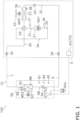
- Fig. 1 is a schematic configuration diagram of the air conditioner 100 according to an embodiment.
- the air conditioner 100 is an apparatus that performs air conditioning of a target space by performing a vapor-compression refrigeration cycle.
- the air conditioner 100 mainly includes an outdoor unit 2, an indoor unit 50, a liquid-refrigerant connection pipe 6 and a gas-refrigerant connection pipe 7 that connect the outdoor unit 2 and the indoor unit 50, a plurality of remote controls 50a, each of which serves as an input device and an output device, and a controller 70 that controls the operation of the air conditioner 100.
- a refrigeration cycle is performed such that refrigerant charged in a refrigerant circuit 10 is compressed, cooled or condensed, decompressed, heated or evaporated, and then compressed again.
- the refrigerant circuit 10 is filled with R32 as a refrigerant for a vapor-compression refrigeration cycle.
- the outdoor unit 2 is connected to the indoor unit 50 through the liquid-refrigerant connection pipe 6 and the gas-refrigerant connection pipe 7 and forms a portion of the refrigerant circuit 10.
- the outdoor unit 2 mainly includes a compressor 21, a four-way switching valve 22, an outdoor heat exchanger 23, an outdoor expansion valve 24, an outdoor fan 25, a liquid-side shutoff valve 29, and a gas-side shutoff valve 30.
- the outdoor unit 2 further includes pipes constituting the refrigerant circuit 10, namely, a discharge pipe 31, a suction pipe 34, an outdoor gas-side pipe 33, and an outdoor liquid-side pipe 32.
- the discharge pipe 31 connects the discharge side of the compressor 21 and a first connection port of the four-way switching valve 22.
- the suction pipe 34 connects the suction side of the compressor 21 and a second connection port of the four-way switching valve 22.
- the outdoor gas-side pipe 33 connects a third connection port of the four-way switching valve 22 and the gas-side shutoff valve 30.
- the outdoor liquid-side pipe 32 extends from a fourth connection port of the four-way switching valve 22 to the liquid-side shutoff valve 29 through the outdoor heat exchanger 23 and the outdoor expansion valve 24.
- the compressor 21 is a device that compresses a low-pressure refrigerant in the refrigeration cycle to a high-pressure refrigerant.
- the compressor 21 is implemented here as a hermetically sealed compressor in which a positive displacement compression element (not illustrated), such as a rotary or scroll compression element, is driven to rotate by a compressor motor M21.
- the compressor motor M21 is used to change volume and has an operating frequency that can be controlled by an inverter.
- connection state of the four-way switching valve 22 can be switched to switch the four-way switching valve 22 between a cooling-operation connection state in which the suction side of the compressor 21 and the gas-side shutoff valve 30 are connected while the discharge side of the compressor 21 and the outdoor heat exchanger 23 are connected and a heating-operation connection state in which the suction side of the compressor 21 and the outdoor heat exchanger 23 are connected while the discharge side of the compressor 21 and the gas-side shutoff valve 30 are connected.
- the outdoor heat exchanger 23 is a heat exchanger that functions as a radiator for a high-pressure refrigerant in the refrigeration cycle during a cooling operation and that functions as an evaporator for a low-pressure refrigerant in the refrigeration cycle during a heating operation.
- the outdoor fan 25 generates an air flow for sucking outdoor air into the outdoor unit 2, allowing the air to exchange heat with the refrigerant in the outdoor heat exchanger 23, and then discharging the air to the outside.
- the outdoor fan 25 is driven to rotate by an outdoor fan motor M25.
- the outdoor expansion valve 24 is an electric expansion valve whose valve opening degree is controllable, and is disposed midway in the outdoor liquid-side pipe 32 between the outdoor heat exchanger 23 and the liquid-side shutoff valve 29.
- the liquid-side shutoff valve 29 is a manual valve that is arranged in a connecting portion between the outdoor liquid-side pipe 32 and the liquid-refrigerant connection pipe 6.
- the gas-side shutoff valve 30 is a manual valve that is arranged in a connecting portion between the outdoor gas-side pipe 33 and the gas-refrigerant connection pipe 7.
- the outdoor unit 2 has various sensors arranged therein.
- the outdoor unit 2 has arranged, near the compressor 21, a suction temperature sensor 35 to detect a suction temperature that is the temperature of refrigerant on the suction side of the compressor 21, a suction pressure sensor 36 to detect a suction pressure that is the pressure of refrigerant on the suction side of the compressor 21, and a discharge pressure sensor 37 to detect a discharge pressure that is the pressure of refrigerant on the discharge side of the compressor 21.
- the outdoor heat exchanger 23 is also provided with an outdoor heat-exchange temperature sensor 38 to detect the temperature of refrigerant flowing through the outdoor heat exchanger 23.
- an outside air temperature sensor 39 is arranged near the outdoor heat exchanger 23 or the outdoor fan 25 to detect the temperature of outdoor air that is sucked into the outdoor unit 2.
- the outdoor unit 2 includes an outdoor-unit control unit 20 that controls the operation of components of the outdoor unit 2.
- the outdoor-unit control unit 20 has a microcomputer including a CPU, a memory, and so on.
- the outdoor-unit control unit 20 is connected to an indoor-unit control unit 57 of indoor unit 50 via a communication line, and transmits and receives control signals and the like. Further, the outdoor-unit control unit 20 is electrically connected to the suction temperature sensor 35, the suction pressure sensor 36, the discharge pressure sensor 37, the outdoor heat-exchange temperature sensor 38, and the outside air temperature sensor 39, and receives a signal from each of the sensors.
- the indoor unit 50 is mounted on the wall surface, the ceiling, or the like of a room that is the target space.
- the indoor unit 50 is connected to the outdoor unit 2 through the liquid-refrigerant connection pipe 6 and the gas-refrigerant connection pipe 7 and forms a portion of the refrigerant circuit 10.
- the indoor unit 50 includes an indoor expansion valve 54, an indoor heat exchanger 52, and an indoor fan 53.
- the indoor unit 50 further includes an indoor liquid refrigerant pipe 58 that connects the liquid-side end of the indoor heat exchanger 52 and the liquid-refrigerant connection pipe 6, and an indoor gas refrigerant pipe 59 that connects the gas-side end of the indoor heat exchanger 52 and the gas-refrigerant connection pipe 7.
- the indoor expansion valve 54 is an electric expansion valve whose valve opening degree is controllable, and is disposed midway in the indoor liquid refrigerant pipe 58.
- the indoor heat exchanger 52 is a heat exchanger that functions as an evaporator for a low-pressure refrigerant in the refrigeration cycle during a cooling operation and that functions as a radiator for a high-pressure refrigerant in the refrigeration cycle during a heating operation.
- the indoor fan 53 generates an air flow for sucking indoor air into the indoor unit 50, allowing the air to exchange heat with the refrigerant in the indoor heat exchanger 52, and then discharging the air to the outside.
- the indoor fan 53 is driven to rotate by an indoor fan motor M53.
- the indoor unit 50 has various sensors arranged therein.
- the indoor unit 50 has arranged therein a refrigerant gas sensor 81 (e.g., a sensor that electrically reacts differently in accordance with the refrigerant gas concentration) to detect the concentration of the refrigerant gas charged in the refrigerant circuit 10, an oxygen gas sensor 82 to detect the oxygen concentration, an air temperature sensor 83 to detect the air temperature in a space where the indoor unit 50 is installed, an infrared sensor 85 to detect a moving object in the space where the indoor unit 50 is installed, and an indoor heat-exchange temperature sensor 86 to detect the temperature of refrigerant flowing through the indoor heat exchanger 52.
- a refrigerant gas sensor 81 e.g., a sensor that electrically reacts differently in accordance with the refrigerant gas concentration
- an oxygen gas sensor 82 to detect the oxygen concentration
- an air temperature sensor 83 to detect the air temperature in a space where the indoor unit 50 is installed
- an infrared sensor 85 to detect a moving object in the space where the indoor unit 50 is installed
- the indoor unit 50 includes the indoor-unit control unit 57, which controls the operation of components of the indoor unit 50.
- the indoor-unit control unit 57 has a microcomputer including a CPU, a memory, and so on.
- the indoor-unit control unit 57 is connected to the outdoor-unit control unit 20 via a communication line, and transmits and receives control signals and the like.
- the indoor-unit control unit 57 is electrically connected to the refrigerant gas sensor 81, the oxygen gas sensor 82, the air temperature sensor 83, the infrared sensor 85, and the indoor heat-exchange temperature sensor 86, and receives a signal from each of the sensors.
- the remote control 50a is an input device used by the user of the indoor unit 50 to input various instructions to switch the operating state of the air conditioner 100.
- the remote control 50a also functions as an output device for informing the user of the operating state of the air conditioner 100 or providing a predetermined notification.
- the remote control 50a and the indoor-unit control unit 57 are connected via a communication line and transmit and receive signals to and from each other.
- the remote control 50a has a built-in speaker.
- the outdoor-unit control unit 20 and the indoor-unit control unit 57 which are connected via a communication line, form the controller 70 that controls the operation of the air conditioner 100.
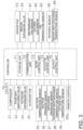
- Fig. 2 is a block diagram schematically illustrating the general configuration of the controller 70 and components connected to the controller 70.
- the controller 70 has a plurality of control modes, and controls the operation of the air conditioner 100 in accordance with the control modes.
- the controller 70 has, as the control modes, a normal operation mode, which is executed under normal conditions, and a refrigerant leak control mode, which is executed when a refrigerant leak occurs.
- the controller 70 is electrically connected to the actuators included in the outdoor unit 2 (specifically, the compressor 21 (the compressor motor M21), the outdoor expansion valve 24, and the outdoor fan 25 (the outdoor fan motor M25)) and the various sensors included in the outdoor unit 2 (such as the suction temperature sensor 35, the suction pressure sensor 36, the discharge pressure sensor 37, the outdoor heat-exchange temperature sensor 38, and the outside air temperature sensor 39).
- the controller 70 is also electrically connected to the actuators included in the indoor unit 50 (specifically, the indoor fan 53 (the indoor fan motor M53) and the indoor expansion valve 54). Further, the controller 70 is electrically connected to the refrigerant gas sensor 81, the oxygen gas sensor 82, the air temperature sensor 83, the infrared sensor 85, the indoor heat-exchange temperature sensor 86, and the remote control 50a.
- the controller 70 mainly includes a storage unit 71, a communication unit 72, a mode control unit 73, an actuator control unit 74, and an output control unit 75. These components in the controller 70 are implemented by the integrated functioning of the components included in the outdoor-unit control unit 20 and/or the indoor-unit control unit 57.
- the storage unit 71 is constituted by, for example, a ROM, a RAM, a flash memory, and so on and includes a volatile storage area and a non-volatile storage area.
- the storage unit 71 stores a control program that defines processes performed by the components of the controller 70.
- the storage unit 71 further stores predetermined information (such as values detected by sensors and commands input to the remote control 50a) in predetermined storage areas, as appropriate, by using the components of the controller 70.
- the communication unit 72 is a function unit that serves as a communication interface for transmitting and receiving signals to and from devices connected to the controller 70.
- the communication unit 72 transmits a predetermined signal to a designated actuator upon receipt of a request from the actuator control unit 74. Further, upon receipt of a signal output from each of the sensors 35 to 39, 81 to 83, 85, and 86 and the remote control 50a, the communication unit 72 stores the signal in a predetermined storage area of the storage unit 71.
- the mode control unit 73 is a function unit that performs processing such as switching between the control modes. When a predetermined refrigerant leak condition is not satisfied for indoor unit 50, the mode control unit 73 sets the control mode to the normal operation mode.
- the mode control unit 73 switches the control mode to the refrigerant leak control mode.
- the actuator control unit 74 controls the operation of the actuators (such as the compressor 21) included in the air conditioner 100 in accordance with the control program.
- the actuator control unit 74 controls the number of revolutions of the compressor 21, the numbers of revolutions of the outdoor fan 25 and the indoor fan 53, the valve opening degree of the outdoor expansion valve 24, the valve opening degree of the indoor expansion valve 54, and the like in real time in accordance with a set temperature, values detected by various sensors, and so on.
- the actuator control unit 74 controls the operation of the actuators so that a predetermined operation can be performed. Specifically, when refrigerant leaks, the actuator control unit 74 interrupts the supply of refrigerant to the indoor unit 50.
- the output control unit 75 is a function unit that controls the operation of the remote control 50a, which serves as a display device.
- the output control unit 75 causes the remote control 50a to output predetermined information so as to present information related to the operating state or conditions to an administrator.
- the output control unit 75 causes the remote control 50a to display various kinds of information such as a set temperature.
- the output control unit 75 causes a display of the remote control 50a to display information indicating the occurrence of a refrigerant leak. Further, the output control unit 75 provides an audible notification indicating the occurrence of a refrigerant leak by using the built-in speaker of the remote control 50a. The output control unit 75 further causes the remote control 50a to display information to promote notification to a service engineer.
- the normal operation mode includes a cooling operation mode and a heating operation mode.
- the controller 70 determines and performs the cooling operation mode or the heating operation mode in accordance with an instruction received from the remote control 50a or the like.
- the connection state of the four-way switching valve 22 is set to a cooling-operation connection state in which the suction side of the compressor 21 and the gas-side shutoff valve 30 are connected while the discharge side of the compressor 21 and the outdoor heat exchanger 23 are connected.
- the refrigerant with which the refrigerant circuit 10 is filled is mainly circulated in the order of the compressor 21, the outdoor heat exchanger 23, the outdoor expansion valve 24, the indoor expansion valve 54, and the indoor heat exchanger 52.
- the refrigerant circuit 10 when the cooling operation mode is started, in the refrigerant circuit 10, the refrigerant is sucked into the compressor 21, compressed, and then discharged.
- a low pressure in the refrigeration cycle corresponds to a suction pressure detected by the suction pressure sensor 36
- a high pressure in the refrigeration cycle corresponds to a discharge pressure detected by the discharge pressure sensor 37.
- capacity control is performed in accordance with cooling load required for the indoor unit 50. Specifically, a target value of the suction pressure is set in accordance with the cooling load required for the indoor unit 50, and the operating frequency of the compressor 21 is controlled such that the suction pressure becomes equal to the target value.
- the gas refrigerant discharged from the compressor 21 travels through the discharge pipe 31 and the four-way switching valve 22, and flows into the gas-side end of the outdoor heat exchanger 23.
- the gas refrigerant that has flowed into the gas-side end of the outdoor heat exchanger 23 releases heat and condenses into a liquid refrigerant in the outdoor heat exchanger 23 by exchanging heat with outdoor-side air supplied by the outdoor fan 25.
- the liquid refrigerant flows out of the liquid-side end of the outdoor heat exchanger 23.
- the liquid refrigerant that has flowed out of the liquid-side end of the outdoor heat exchanger 23 travels through the outdoor liquid-side pipe 32, the outdoor expansion valve 24, the liquid-side shutoff valve 29, and the liquid-refrigerant connection pipe 6, and flows into the indoor unit 50.
- the outdoor expansion valve 24 is controlled to be fully opened.
- the refrigerant that has flowed into the indoor unit 50 travels through a portion of the indoor liquid refrigerant pipe 58, and flows into the indoor expansion valve 54.
- the refrigerant that has flowed into the indoor expansion valve 54 is decompressed by the indoor expansion valve 54 until the refrigerant becomes a low-pressure refrigerant in the refrigeration cycle, and then flows into the liquid-side end of the indoor heat exchanger 52.
- the valve opening degree of the indoor expansion valve 54 is controlled such that the degree of superheating of refrigerant sucked into the compressor 21 becomes equal to a predetermined degree of superheating.
- the degree of superheating of refrigerant sucked into the compressor 21 is calculated by the controller 70 by using the temperature detected by the suction temperature sensor 35 and the pressure detected by the suction pressure sensor 36.
- the refrigerant that has flowed into the liquid-side end of the indoor heat exchanger 52 evaporates into a gas refrigerant in the indoor heat exchanger 52 by exchanging heat with indoor air supplied by the indoor fan 53.
- the gas refrigerant flows out of the gas-side end of the indoor heat exchanger 52.
- the gas refrigerant that has flowed out of the gas-side end of the indoor heat exchanger 52 flows to the gas-refrigerant connection pipe 7 through the indoor gas refrigerant pipe 59.
- the refrigerant flowing through the gas-refrigerant connection pipe 7 travels through the gas-side shutoff valve 30, the outdoor gas-side pipe 33, the four-way switching valve 22, and the suction pipe 34, and is again sucked into the compressor 21.
- connection state of the four-way switching valve 22 is set to a heating-operation connection state in which the suction side of the compressor 21 and the outdoor heat exchanger 23 are connected while the discharge side of the compressor 21 and the gas-side shutoff valve 30 are connected.
- the refrigerant with which the refrigerant circuit 10 is filled is mainly circulated in the order of the compressor 21, the indoor heat exchanger 52, the indoor expansion valve 54, the outdoor expansion valve 24, and the outdoor heat exchanger 23.
- the refrigerant circuit 10 when the heating operation mode is started, in the refrigerant circuit 10, the refrigerant is sucked into the compressor 21, compressed, and then discharged.
- a low pressure in the refrigeration cycle corresponds to a suction pressure detected by the suction pressure sensor 36
- a high pressure in the refrigeration cycle corresponds to a discharge pressure detected by the discharge pressure sensor 37.
- capacity control is performed in accordance with the heating load required for the indoor unit 50. Specifically, a target value of the discharge pressure is set in accordance with the heating load required for the indoor unit 50, and the operating frequency of the compressor 21 is controlled such that the discharge pressure becomes equal to the target value.
- the gas refrigerant discharged from the compressor 21 flows through the discharge pipe 31, the four-way switching valve 22, the outdoor gas-side pipe 33, and the gas-refrigerant connection pipe 7, and then flows into the indoor unit 50 through the indoor gas refrigerant pipe 59.
- the refrigerant that has flowed into the indoor unit 50 travels through the indoor gas refrigerant pipe 59, and flows into the gas-side end of the indoor heat exchanger 52.
- the refrigerant that has flowed into the gas-side end of the indoor heat exchanger 52 releases heat and condenses into a liquid refrigerant in the indoor heat exchanger 52 by exchanging heat with indoor air supplied by the indoor fan 53.
- the liquid refrigerant flows out of the liquid-side end of the indoor heat exchanger 52.
- the refrigerant that has flowed out of the liquid-side end of the indoor heat exchanger 52 flows to the liquid-refrigerant connection pipe 6 through the indoor liquid refrigerant pipe 58 and the indoor expansion valve 54.
- the valve opening degree of the indoor expansion valve 54 is controlled to be fully opened.
- the refrigerant flowing through the liquid-refrigerant connection pipe 6 flows into the outdoor expansion valve 24 through the liquid-side shutoff valve 29 and the outdoor liquid-side pipe 32.
- the refrigerant that has flowed into the outdoor expansion valve 24 is decompressed until the refrigerant becomes a low-pressure refrigerant in the refrigeration cycle, and then flows into the liquid-side end of the outdoor heat exchanger 23.
- the valve opening degree of the outdoor expansion valve 24 is controlled such that the degree of superheating of refrigerant sucked into the compressor 21 becomes equal to a predetermined degree of superheating.
- the refrigerant that has flowed into the liquid-side end of the outdoor heat exchanger 23 evaporates into a gas refrigerant in the outdoor heat exchanger 23 by exchanging heat with outdoor air supplied by the outdoor fan 25.
- the gas refrigerant flows out of the gas-side end of the outdoor heat exchanger 23.
- the refrigerant that has flowed out of the gas-side end of the outdoor heat exchanger 23 travels through the four-way switching valve 22 and the suction pipe 34, and is again sucked into the compressor 21.
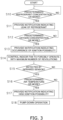
- the following describes an example process flow for the refrigerant leak control mode, which is executed by the controller 70 when a refrigerant leak occurs in the normal operation mode with reference to a flowchart illustrated in Fig. 3 .
- step S 10 when the normal operation mode of the cooling operation mode or heating operation mode is being executed, the controller 70 determines whether the refrigerant concentration detected by the refrigerant gas sensor 81 is greater than or equal to a predetermined refrigerant concentration.
- the predetermined refrigerant concentration is determined in advance in accordance with the type of the refrigerant charged in the refrigerant circuit 10 (in this embodiment, R32) and is stored in the storage unit 71. If the controller 70 determines that the refrigerant concentration detected by the refrigerant gas sensor 81 is greater than or equal to the predetermined refrigerant concentration, the process proceeds to step S11. On the other hand, if the refrigerant concentration detected by the refrigerant gas sensor 81 is less than the predetermined refrigerant concentration, the normal operation mode remains continuously active and step S10 is repeatedly performed.
- step S11 the controller 70 starts the refrigerant leak control mode and causes the output control unit 75 to display, on the display of the remote control 50a, information indicating a leak of refrigerant as text information. Further, the controller 70 causes the output control unit 75 to provide a notification indicating the leak of refrigerant as audio information from the speaker of the remote control 50a.
- step S12 the controller 70 determines whether the oxygen concentration detected by the oxygen gas sensor 82 is greater than or equal to a predetermined oxygen concentration.
- the predetermined oxygen concentration is determined in advance in accordance with the type of the refrigerant charged in the refrigerant circuit 10 (in this embodiment, R32) and is stored in the storage unit 71. If the controller 70 determines that the oxygen concentration detected by the oxygen gas sensor 82 is greater than or equal to the predetermined oxygen concentration, the process proceeds to step S13. On the other hand, if the oxygen concentration detected by the oxygen gas sensor 82 is less than the predetermined oxygen concentration, step S12 is repeatedly performed.
- step S13 the controller 70 causes the output control unit 75 to display, on the display of the remote control 50a, information indicating that an ignition possibility has occurred due to the leak of refrigerant as text information. Further, the controller 70 causes the output control unit 75 to provide a notification indicating that an ignition possibility has occurred due to the leak of refrigerant as audio information from the speaker of the remote control 50a (notification with a greater sound than that in step S11).
- step S14 the controller 70 controls the indoor fan 53 to forcibly operate with a maximum number of revolutions. This allows the refrigerant that has leaked to be stirred and can suppress a local increase in concentration.
- step S15 the controller 70 determines whether the infrared sensor 85 has detected a moving object such as a person or an animal in the room. If the controller 70 determines that the infrared sensor 85 has detected an object, the process proceeds to step S16. On the other hand, if it is determined that no object is detected by the infrared sensor 85, the process proceeds to step S 18.
- step S16 the controller 70 determines whether the temperature of air in the room, which is detected by the air temperature sensor 83, is greater than or equal to a predetermined air temperature.
- the predetermined air temperature is determined in advance in accordance with the type of the refrigerant charged in the refrigerant circuit 10 (in this embodiment, R32) and is stored in the storage unit 71. In most refrigerants, including R32, the ignition possibility increases as the air temperature increases. If the controller 70 determines that the temperature of air in the room, which is detected by the air temperature sensor 83, is greater than or equal to the predetermined air temperature, the process proceeds to step S17. On the other hand, if it is determined that the temperature is not greater than or equal to the predetermined air temperature, the process proceeds to step S18.
- step S17 the controller 70 causes the output control unit 75 to display, on the display of the remote control 50a, information indicating that the ignition possibility becomes high due to the leak of refrigerant as text information. Further, the controller 70 causes the output control unit 75 to provide a notification indicating that the ignition possibility becomes high due to the leak of refrigerant as audio information from the speaker of the remote control 50a (notification with a greater sound than that in step S13).
- step S18 the controller 70 performs a pump-down operation.
- the pump-down operation while the connection state of the four-way switching valve 22 is set to the connection state in the cooling operation mode, the outdoor expansion valve 24 is closed, the compressor 21 is driven, the outdoor fan 25 is driven, and the outdoor heat exchanger 23 is caused to function as a condenser for refrigerant. Accordingly, within the refrigerant circuit 10, refrigerant present on the indoor unit 50 side is collected before the refrigerant reaches the outdoor expansion valve 24 from the discharge side of the compressor 21 of the outdoor unit 2 through the outdoor heat exchanger 23, thereby suppressing a further leak of refrigerant from a leak portion of the indoor unit 50.
- the pump-down operation is performed, with the connection state of the four-way switching valve 22 remaining unchanged.
- the pump-down operation is performed after the connection state of the four-way switching valve 22 is switched to that in the cooling operation mode.
- the pump-down operation is finished when the pressure detected by the suction pressure sensor 36 becomes less than or equal to a predetermined termination pressure. The driving of the compressor 21 is stopped, and the operation of the air conditioner 100 is stopped.
- the oxygen gas sensor 82 is used to detect an oxygen gas.
- the refrigerant concentration of the refrigerant that has leaked is greater than or equal to a predetermined refrigerant concentration and that the oxygen gas concentration is greater than or equal to a predetermined oxygen concentration, a notification is provided indicating that an ignition possibility has occurred.
- the concentrations of both a refrigerant gas and an oxygen gas are detected. This enables more accurate determination of an ignition possibility than the case where only a refrigerant gas that has leaked is detected.
- the indoor unit 50 of the air conditioner 100 when used in a low-oxygen-concentration environment such as in a specific factory, a slight leak of refrigerant may not lead directly to the occurrence of an ignition possibility. In this case, even if refrigerant leaks, it is possible to determine that the ignition possibility is low.
- a moving object is also detected by using the infrared sensor 85.
- the infrared sensor 85 detects the presence of a moving object in the room, it is determined whether the ignition possibility is high by using the air temperature sensor 83, and the moving object can be notified of a high ignition possibility. If no moving object is present in the target space, such as when the infrared sensor 85 detects no object, a notification by sound with a high volume is not provided. This can suppress the occurrence of a loud sound more than necessary.
- the determination of whether the ignition possibility is high can be based on air temperature or air humidity at which ignition is likely to occur in accordance with the type of the refrigerant charged in the refrigerant circuit 10. Thus, whether the ignition possibility is high can be more accurately determined.
- the indoor fan 53 when it is determined that an ignition possibility has occurred, the indoor fan 53 is forcibly driven with a maximum number of revolutions. This can suppress the occurrence of a local increase in refrigerant concentration within the room, and ignition can be less likely to occur.
- the refrigerant to be charged in the refrigerant circuit 10 is not limited to this, and examples of the refrigerant other than R32 may include flammable refrigerants classified in Class A3 of ASHRAE 34 Refrigerant Safety Classification, low flammable refrigerants classified in Class A2 of ASHRAE 34 Refrigerant Safety Classification, and mildly flammable refrigerants classified in Class A2L of ASHRAE 34 Refrigerant Safety Classification. These refrigerants can also be ignited when leaking, and thus effects similar to those of the embodiment described above can be achieved.
- refrigerant to be charged in the refrigerant circuit 10, other than R32 may include refrigerants with lower GWP than R32 (a natural refrigerant such as R717 and, R170, R1270, R290, R600, R600a, R152a, and a refrigerant mixture thereof). Even when such a refrigerant as having a low GWP value is used, a leak can be appropriately detected and a leak notification is provided. This ensures that necessary countermeasures against the leak can be taken.
- the type of notification is not limited to these.
- the lamp may be turned on or made to blink.
- the notification may be provided in a different way in accordance with the determined level of the ignition possibility such that the amount of emission of light is increased, the color of emitted light is changed, or the blinking speed is increased.
- the controller 70 When the controller 70 is connected to an external remote monitoring device or the like, which is constituted by a computer, via the communication unit 72 so that they can communicate with each other over a communication network, the controller 70 may transmit to the external remote monitoring device or the like information indicating that refrigerant has leaked, an ignition possibility has occurred, and the ignition possibility is high.
- a service engineer who specializes in taking countermeasures against refrigerant leaks that are being monitored in the remote monitoring device can also be appropriately informed of the situation.
- control of the air conditioner 100 which is performed after an ignition possibility has occurred, is not limited to this.
- control may be performed to reduce the frequency of the compressor 21 after a leak.
- the indoor expansion valve 54 may be closed so as not to supply further refrigerant to the indoor heat exchanger 52.
- the operation of the air conditioner 100 may be continuously performed, with the driving of the compressor 21 reduced, and in a stage where the ignition possibility becomes high, a pump-down operation may be performed to stop the air conditioner 100.
- the operation of the air conditioner 100 may be continuously performed, with the indoor fan 53 forcibly driven with a maximum number of revolutions, and in a stage where the ignition possibility becomes high, a pump-down operation may be performed to stop the air conditioner 100.
- an air conditioner 100a may be used that further includes an air humidity sensor 84 to detect the air humidity in the space where the indoor unit 50 is installed.
- the air humidity sensor 84 is also electrically connected to the indoor-unit control unit 57 so that a detection signal can be transmitted.
- steps S20 to S26, S28, and S29 is similar to that of steps S10 to S18 according to the embodiment described above, and the processing of step S27, described below, may be added after step S26.
- step S27 the controller 70 determines whether the humidity of indoor air detected by the air humidity sensor 84 is greater than or equal to a predetermined air humidity.
- the predetermined air humidity is determined in advance in accordance with the type of the refrigerant charged in the refrigerant circuit 10 (in this embodiment, R32) and is stored in the storage unit 71. If the controller 70 determines that the humidity of indoor air detected by the air humidity sensor 84 is greater than or equal to the predetermined air humidity, the process proceeds to step S28. On the other hand, if it is determined that the humidity is not greater than or equal to the predetermined air humidity, the process proceeds to step S29.
- the ignition possibility may be determined by using the air humidity sensor 84 without using the air temperature sensor 83.
- the refrigerant gas concentration range condition, the oxygen concentration range condition, the air temperature range condition, and the air humidity range condition may be stored in advance in accordance with the type of the refrigerant charged in the refrigerant circuit 10, and the ignition possibility may be determined specifically in accordance with the type of the refrigerant charged in the refrigerant circuit 10.
- a refrigerant leak it may be determined that refrigerant has leaked by, for example, detecting a reduction in the pressure detected by the suction pressure sensor 36 or the discharge pressure sensor 37 (by determining that a predetermined pressure condition is satisfied). In this way, a refrigerant leak is determined by using a detected value of refrigerant pressure in the refrigerant circuit 10, thereby confirming that a leak from the refrigerant circuit 10 has occurred (rather than the detection of refrigerant that has leaked from any other refrigerant system).
- step S10 in the refrigerant leak control mode the determination is made by both detecting the refrigerant concentration by the refrigerant gas sensor 81 and detecting a reduction in the pressure detected by the suction pressure sensor 36 or the discharge pressure sensor 37, thereby more accurately determining a refrigerant leak to increase reliability.
- a pressure value used as a determination criterion may be stored in the storage unit 71 in advance in accordance with the operation status, and the determination may be made by comparison with the pressure value serving as the determination criterion.
- a reduction in the pressure detected by the suction pressure sensor 36 or the discharge pressure sensor 37, described above, may be detected by, for example, detecting a reduction in saturation temperature in the refrigerant circuit 10.
- a reduction in saturation temperature determined from the outdoor heat-exchange temperature sensor 38 may be detected, or a reduction in saturation temperature corresponding to a saturation pressure determined from the discharge pressure sensor 37.
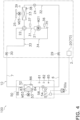
- the concentration of refrigerant that has leaked may be determined by using, as illustrated in Fig. 7 and Fig. 8 , an air conditioner 100b that further includes an ultrasonic sensor 87.
- the ultrasonic sensor 87 is constituted by an ultrasonic transmitter that emits an ultrasound wave to the interior of the room, and an ultrasonic receiver that receives an ultrasound wave reflected from the wall surface or the like of the room. If refrigerant leaks within the room, velocity changes when the ultrasound wave travels through a portion where the concentration of the refrigerant is high, and the time taken from emission to reception of the ultrasound wave changes accordingly. Based on the change, the refrigerant concentration can be determined.
- the ultrasonic sensor 87 can compare the specific gravity of refrigerant to be charged in the refrigerant circuit 10 with that of air to predict and use a portion where the refrigerant is likely to build up when leaking, such that the ultrasound wave is emitted downward when the refrigerant has a great specific gravity and the ultrasound wave is emitted upward when the refrigerant has a small specific gravity.
- the ultrasonic sensor 87 is also electrically connected to the indoor-unit control unit 57 so that a detection signal can be transmitted.
- the determination of the refrigerant concentration in step S10 in the refrigerant leak control mode may be performed by using both detection performed by the refrigerant gas sensor 81 and detection of the refrigerant concentration using the ultrasonic sensor 87. In this case, if the value detected by any one of the sensors is determined to be greater than or equal to a predetermined refrigerant concentration, the process may proceed to the subsequent step.
- the air conditioner 100 has been described as an example in which the indoor unit 50 and the outdoor unit 2 are separately arranged in remote locations.
- an air conditioner may be configured such that the internal components of the indoor unit 50 and the internal components of the outdoor unit 2 according to the embodiment described above are housed in a single housing, and may be used in such a manner that the single housing is mounted over the indoor side and the outdoor side.
- a controller of ventilation equipment which is installed in the building separately from the air conditioner 100, and the controller 70 of the air conditioner 100 are configured to be capable of communicating with each other, and, when the indoor fan 53 is caused to forcibly operate if refrigerant leaks, a fan included in the ventilation equipment may also be caused to forcibly operate at the same time.
Landscapes
- Engineering & Computer Science (AREA)
- Mechanical Engineering (AREA)
- General Engineering & Computer Science (AREA)
- Chemical & Material Sciences (AREA)
- Combustion & Propulsion (AREA)
- Physics & Mathematics (AREA)
- Thermal Sciences (AREA)
- Air Conditioning Control Device (AREA)
Claims (11)
- Kühlgerät (100, 100a, 100b) einschließlich eines Kältemittelkreislaufs (10), in den ein Kältemittel eingefüllt ist und der einen Kühlzyklus durchführt, wobei das Kühlgerät (100) Folgendes umfasst:einen Kältemittelgassensor (81) zum Erfassen eines Kältemittelgases in einem Zielraum, in dem mindestens ein Teil des Kühlgeräts angeordnet werden kann; undeinen Sauerstoffgassensor (82) zum Erfassen eines Sauerstoffgases im Zielraum,eine Steuereinheit (70), die so konfiguriert ist, dass sie eine Benachrichtigung bereitstellt, die anzeigt, dass eine Zündmöglichkeit aufgetreten ist, oder einen Betrieb des Kühlzyklus im Kältemittelkreislauf ändert oder den Betrieb des Kühlzyklus im Kältemittelkreislauf beendet, und zwar auf der Grundlage der erfassten Informationen, die von dem Kältemittelgassensor und dem Sauerstoffgassensor erhalten werden.
- Kühlgerät nach Anspruch 1, wobei
das in den Kältemittelkreislauf eingefüllte Kältemittel ein Einkomponentenkältemittel ist, das eines der folgenden Kältemittel ist: ein entflammbares Kältemittel, ein schwer entflammbares Kältemittel, ein leicht entflammbares Kältemittel und ein Ammoniak-Kältemittel oder ein Kältemittelgemisch aus zwei oder mehreren davon. - Kühlgerät nach Anspruch 1, wobei
das in den Kältemittelkreislauf eingefüllte Kältemittel R32 oder ein Kältemittel mit einem niedrigeren GWP-Wert als R32 ist. - Kühlgerät nach Anspruch 1, weiter umfassendeinen Lufttemperatursensor (83), der den Zielraum als Erfassungszielraum verwendet, wobeidie Steuereinheit eine Benachrichtigung bereitstellt, die anzeigt, dass eine Zündmöglichkeit aufgetreten ist, oder einen Betrieb des Kühlzyklus im Kältemittelkreislauf ändert oder den Betrieb des Kühlzyklus im Kältemittelkreislauf beendet, und zwar auf der Grundlage der erfassten Informationen, die von dem Kältemittelgassensor, dem Sauerstoffgassensor und dem Lufttemperatursensor erhalten werden.
- Kühlgerät nach Anspruch 4, wobei
die Steuereinheit eine erste Bestimmung auf der Grundlage der erfassten Informationen durchführt, die von dem Kältemittelgassensor und dem Sauerstoffgassensor erhalten werden, eine zweite Bestimmung auf der Grundlage der erfassten Informationen durchführt, die von dem Kältemittelgassensor, dem Sauerstoffgassensor und dem Lufttemperatursensor erhalten werden, und die Benachrichtigung bereitstellt oder den Betrieb in Übereinstimmung mit einem Ergebnis der ersten Bestimmung und einem Ergebnis der zweiten Bestimmung auf eine andere Weise ändert oder beendet. - Kühlgerät (100a) nach Anspruch 1, weiter umfassendeinen Luftfeuchtigkeitssensor (84), der den Zielraum als Erfassungszielraum verwendet, wobeidie Steuereinheit eine Benachrichtigung bereitstellt, die anzeigt, dass eine Zündmöglichkeit aufgetreten ist, oder einen Betrieb des Kühlzyklus im Kältemittelkreislauf ändert oder den Betrieb des Kühlzyklus im Kältemittelkreislauf beendet, und zwar auf der Grundlage der erfassten Informationen, die von dem Kältemittelgassensor, dem Sauerstoffgassensor und dem Luftfeuchtigkeitssensor erhalten werden.
- Kühlgerät nach Anspruch 6, wobei
die Steuereinheit eine erste Bestimmung auf der Grundlage der erfassten Informationen durchführt, die von dem Kältemittelgassensor und dem Sauerstoffgassensor erhalten werden, eine zweite Bestimmung auf der Grundlage der erfassten Informationen durchführt, die von dem Kältemittelgassensor, dem Sauerstoffgassensor und dem Luftfeuchtigkeitssensor erhalten werden, und die Benachrichtigung bereitstellt oder den Betrieb in Übereinstimmung mit einem Ergebnis der ersten Bestimmung und einem Ergebnis der zweiten Bestimmung auf eine andere Weise ändert oder beendet. - Kühlgerät nach Anspruch 1, weiter umfassendein Gebläse (53), das einen Luftstrom im Zielraum erzeugt, wobeidie Steuereinheit das Gebläse veranlasst, auf der Grundlage der erfassten Informationen, die von dem Kältemittelgassensor und dem Sauerstoffgassensor erhalten werden, zwangsweise Luft zu blasen.
- Kühlgerät nach Anspruch 1, weiter umfassendeinen Sensor (85) zur Erfassung von Personen, der ein sich bewegendes Objekt im Zielraum erfasst, wobeidie Steuereinheit eine Benachrichtigung bereitstellt, die anzeigt, dass eine Zündmöglichkeit aufgetreten ist, oder einen Betrieb des Kühlzyklus im Kältemittelkreislauf ändert oder den Betrieb des Kühlzyklus im Kältemittelkreislauf beendet, und zwar auf der Grundlage der erfassten Informationen, die von dem Kältemittelgassensor, dem Sauerstoffgassensor und dem Sensor zur Erfassung von Personen erhalten werden.
- Kühlgerät nach Anspruch 1, weiter umfassendeinen Kältemitteldrucksensor (36, 37), der einen Druck des Kältemittels im Kältemittelkreislauf erfasst, wobeidie Steuereinheit eine Benachrichtigung bereitstellt, die anzeigt, dass eine Zündmöglichkeit aufgetreten ist, oder einen Betrieb des Kühlzyklus im Kältemittelkreislauf ändert oder den Betrieb des Kühlzyklus im Kältemittelkreislauf beendet, und zwar auf der Grundlage der erfassten Informationen, die von dem Kältemittelgassensor, dem Sauerstoffgassensor und dem Kältemitteldrucksensor erhalten werden.
- Kühlgerät (100b) nach Anspruch 1, weiter umfassendeinen Ultraschallsensor (87), der, während er eine Ultraschallwelle in den Zielraum abgibt, eine reflektierte Welle der Ultraschallwelle aus dem Zielraum erfasst, wobeidie Steuereinheit eine Benachrichtigung bereitstellt, die anzeigt, dass eine Zündmöglichkeit aufgetreten ist, oder einen Betrieb des Kühlzyklus im Kältemittelkreislauf ändert oder den Betrieb des Kühlzyklus im Kältemittelkreislauf beendet, und zwar auf der Grundlage der erfassten Informationen, die von dem Kältemittelgassensor, dem Sauerstoffgassensor und dem Ultraschallsensor erhalten werden.
Applications Claiming Priority (2)
| Application Number | Priority Date | Filing Date | Title |
|---|---|---|---|
| JP2017072646A JP6477767B2 (ja) | 2017-03-31 | 2017-03-31 | 冷凍装置 |
| PCT/JP2018/012122 WO2018181173A1 (ja) | 2017-03-31 | 2018-03-26 | 冷凍装置 |
Publications (3)
| Publication Number | Publication Date |
|---|---|
| EP3604980A1 EP3604980A1 (de) | 2020-02-05 |
| EP3604980A4 EP3604980A4 (de) | 2020-11-25 |
| EP3604980B1 true EP3604980B1 (de) | 2025-02-12 |
Family
ID=63676006
Family Applications (1)
| Application Number | Title | Priority Date | Filing Date |
|---|---|---|---|
| EP18774971.8A Active EP3604980B1 (de) | 2017-03-31 | 2018-03-26 | Kühlgerät |
Country Status (5)
| Country | Link |
|---|---|
| US (1) | US11268718B2 (de) |
| EP (1) | EP3604980B1 (de) |
| JP (1) | JP6477767B2 (de) |
| CN (1) | CN110402359B (de) |
| WO (1) | WO2018181173A1 (de) |
Families Citing this family (30)
| Publication number | Priority date | Publication date | Assignee | Title |
|---|---|---|---|---|
| US10119738B2 (en) | 2014-09-26 | 2018-11-06 | Waterfurnace International Inc. | Air conditioning system with vapor injection compressor |
| US10871314B2 (en) | 2016-07-08 | 2020-12-22 | Climate Master, Inc. | Heat pump and water heater |
| US10866002B2 (en) | 2016-11-09 | 2020-12-15 | Climate Master, Inc. | Hybrid heat pump with improved dehumidification |
| EP3663681B1 (de) * | 2017-08-03 | 2023-06-07 | Daikin Industries, Ltd. | Kühlvorrichtung |
| US20190170600A1 (en) * | 2017-12-01 | 2019-06-06 | Johnson Controls Technology Company | Systems and methods for detecting refrigerant leaks in heating, ventilating, and air conditioning (hvac) systems |
| US11592215B2 (en) | 2018-08-29 | 2023-02-28 | Waterfurnace International, Inc. | Integrated demand water heating using a capacity modulated heat pump with desuperheater |
| US10941953B2 (en) * | 2018-10-17 | 2021-03-09 | Lennox Industries Inc. | HVAC system and method of circulating flammable refrigerant |
| US10767882B2 (en) * | 2018-10-17 | 2020-09-08 | Lennox Industries Inc. | Refrigerant pump down for an HVAC system |
| AU2018450374B2 (en) | 2018-11-20 | 2022-03-17 | Mitsubishi Electric Corporation | Air-conditioning apparatus |
| KR101989752B1 (ko) * | 2018-11-21 | 2019-06-14 | 대성히트펌프 주식회사 | 준가연성 냉매를 적용한 히트펌프 안전운전제어시스템 및 안전운전제어방법 |
| US10928091B2 (en) * | 2019-01-24 | 2021-02-23 | Lennox Industries Inc. | Systems and methods for pumping down flammable refrigerant |
| US10816232B2 (en) * | 2019-01-24 | 2020-10-27 | Lennox Industries Inc. | Systems and methods for pumping down flammable refrigerant |
| JP7258576B2 (ja) * | 2019-01-25 | 2023-04-17 | 三菱重工サーマルシステムズ株式会社 | 空気調和機及び空気調和機の運転方法 |
| CA3081986A1 (en) | 2019-07-15 | 2021-01-15 | Climate Master, Inc. | Air conditioning system with capacity control and controlled hot water generation |
| US11231198B2 (en) * | 2019-09-05 | 2022-01-25 | Trane International Inc. | Systems and methods for refrigerant leak detection in a climate control system |
| US12025337B2 (en) * | 2020-03-19 | 2024-07-02 | Carrier Corporation | Baffle for directing refrigerant leaks |
| WO2021220355A1 (ja) * | 2020-04-27 | 2021-11-04 | 三菱電機株式会社 | 冷凍サイクル装置 |
| US11732916B2 (en) | 2020-06-08 | 2023-08-22 | Emerson Climate Technologies, Inc. | Refrigeration leak detection |
| SE544675C2 (en) * | 2020-07-13 | 2022-10-11 | Flaektgroup Sweden Ab | A method for evacuation of contaminated air and prevention of ingition in an air handling system |
| US11885516B2 (en) * | 2020-08-07 | 2024-01-30 | Copeland Lp | Refrigeration leak detection |
| US11754324B2 (en) | 2020-09-14 | 2023-09-12 | Copeland Lp | Refrigerant isolation using a reversing valve |
| US12196462B2 (en) | 2021-03-23 | 2025-01-14 | Copeland Lp | Heat-pump system with multiway valve |
| US11940188B2 (en) | 2021-03-23 | 2024-03-26 | Copeland Lp | Hybrid heat-pump system |
| US12480673B2 (en) * | 2021-06-18 | 2025-11-25 | Mitsubishi Electric Corporation | Air-conditioning apparatus |
| CN115523583A (zh) * | 2021-06-25 | 2022-12-27 | 重庆美的制冷设备有限公司 | 空调器的制氧控制方法、空调器及存储介质 |
| US12181189B2 (en) | 2021-11-10 | 2024-12-31 | Climate Master, Inc. | Ceiling-mountable heat pump system |
| US12487008B2 (en) | 2022-01-14 | 2025-12-02 | Trane International Inc. | Method of commissioning an HVAC system |
| JP2023152838A (ja) * | 2022-03-31 | 2023-10-17 | 旭化成エレクトロニクス株式会社 | リスク情報提供装置、リスク情報提供システム、リスク情報提供方法およびリスク情報提供プログラム |
| EP4269892B1 (de) | 2022-04-28 | 2025-06-04 | Weiss Technik GmbH | Prüfkammer und verfahren |
| US12117191B2 (en) | 2022-06-24 | 2024-10-15 | Trane International Inc. | Climate control system with improved leak detector |
Family Cites Families (21)
| Publication number | Priority date | Publication date | Assignee | Title |
|---|---|---|---|---|
| JPH0820151B2 (ja) * | 1990-11-09 | 1996-03-04 | 株式会社ユニシアジェックス | 空調装置 |
| JP2000249435A (ja) * | 1999-03-01 | 2000-09-14 | Daikin Ind Ltd | 冷凍装置及び冷凍装置の冷媒漏れ検知方法 |
| JP3159200B2 (ja) * | 1999-03-02 | 2001-04-23 | ダイキン工業株式会社 | 空気調和装置 |
| JP2002195718A (ja) * | 2000-12-28 | 2002-07-10 | Nakano Refrigerators Co Ltd | ショーケース等の集中管理装置 |
| JP2002228281A (ja) * | 2001-01-31 | 2002-08-14 | Sanyo Electric Co Ltd | 空気調和機 |
| JP2002228271A (ja) * | 2001-02-05 | 2002-08-14 | Exedy Corp | 集熱装置用反射面部材及びその製造方法 |
| CN1314930C (zh) * | 2002-01-15 | 2007-05-09 | 株式会社东芝 | 具有对冷媒泄漏进行告警的告警装置的电冰箱 |
| JP2012013348A (ja) * | 2010-07-02 | 2012-01-19 | Panasonic Corp | 空気調和機 |
| US10024590B2 (en) * | 2011-12-21 | 2018-07-17 | Xergy Inc. | Electrochemical compressor refrigeration appartus with integral leak detection system |
| JP5673612B2 (ja) * | 2012-06-27 | 2015-02-18 | 三菱電機株式会社 | 冷凍サイクル装置 |
| JP2014035171A (ja) * | 2012-08-10 | 2014-02-24 | Mitsubishi Electric Corp | 空気調和機、空気調和方法及びプログラム |
| WO2014153552A1 (en) * | 2013-03-21 | 2014-09-25 | Cornell University | Building power management systems |
| JP5785349B2 (ja) * | 2013-05-17 | 2015-09-30 | パナソニック インテレクチュアル プロパティ コーポレーション オブアメリカPanasonic Intellectual Property Corporation of America | センサー搭載装置 |
| AU2015277826B2 (en) * | 2014-06-19 | 2018-01-25 | Mitsubishi Electric Corporation | Indoor unit of air-conditioning apparatus and air-conditioning apparatus including the indoor unit |
| JP6408324B2 (ja) * | 2014-09-29 | 2018-10-17 | 日立ジョンソンコントロールズ空調株式会社 | 空気調和機の室内機 |
| CN104566864B (zh) * | 2014-12-31 | 2017-12-12 | 广东美的制冷设备有限公司 | 使用可燃冷媒的空调器和控制方法 |
| US10760839B2 (en) * | 2015-03-26 | 2020-09-01 | Mitsubishi Electric Corporation | Indoor unit of air-conditioning apparatus having leaked refrigerant ventilation |
| JP2016200349A (ja) * | 2015-04-13 | 2016-12-01 | エイ・ジー・サービス株式会社 | 冷媒漏洩検知システム及び冷媒漏洩検知方法 |
| JPWO2017037841A1 (ja) | 2015-08-31 | 2018-03-29 | 三菱電機株式会社 | 冷凍サイクル装置及びその設置方法 |
| CN205264013U (zh) * | 2015-12-29 | 2016-05-25 | 山东三沐环保科技有限公司 | 一种碳氢冷媒泄漏预警装置 |
| US20190063808A1 (en) * | 2016-04-28 | 2019-02-28 | Mitsubishi Electric Corporation | Refrigeration cycle apparatus |
-
2017
- 2017-03-31 JP JP2017072646A patent/JP6477767B2/ja active Active
-
2018
- 2018-03-26 EP EP18774971.8A patent/EP3604980B1/de active Active
- 2018-03-26 WO PCT/JP2018/012122 patent/WO2018181173A1/ja not_active Ceased
- 2018-03-26 CN CN201880012625.6A patent/CN110402359B/zh active Active
- 2018-03-26 US US16/492,992 patent/US11268718B2/en active Active
Also Published As
| Publication number | Publication date |
|---|---|
| JP6477767B2 (ja) | 2019-03-06 |
| EP3604980A4 (de) | 2020-11-25 |
| CN110402359A (zh) | 2019-11-01 |
| EP3604980A1 (de) | 2020-02-05 |
| JP2018173250A (ja) | 2018-11-08 |
| US20200049361A1 (en) | 2020-02-13 |
| US11268718B2 (en) | 2022-03-08 |
| CN110402359B (zh) | 2021-04-30 |
| WO2018181173A1 (ja) | 2018-10-04 |
Similar Documents
| Publication | Publication Date | Title |
|---|---|---|
| EP3604980B1 (de) | Kühlgerät | |
| EP3604982B1 (de) | Innenraumeinheit einer kühlvorrichtung | |
| US11041666B2 (en) | Refrigeration apparatus | |
| JP6697890B2 (ja) | 空気調和機用のユニット機構、及びこれを備えた空気調和機 | |
| JP6641459B2 (ja) | 空気調和装置 | |
| CN107709902A (zh) | 空调系统 | |
| WO2021010233A1 (ja) | 冷媒漏洩報知装置及び冷媒漏洩報知装置を備えた冷凍サイクルシステム | |
| US12140329B2 (en) | Installation assistance system for air conditioning device, installation assistance device, and installation assistance method | |
| CN114096793A (zh) | 冷冻循环系统 | |
| JP2002147905A (ja) | 冷凍装置 | |
| US12031732B2 (en) | Air conditioning system, operation control method therefor, and operation control device for air conditioning system | |
| JP2025148005A (ja) | 冷凍装置 | |
| JP2025028288A (ja) | 空気調和装置 | |
| WO2023228479A1 (ja) | 空調システム | |
| EP3882536A1 (de) | Klimaanlage |
Legal Events
| Date | Code | Title | Description |
|---|---|---|---|
| STAA | Information on the status of an ep patent application or granted ep patent |
Free format text: STATUS: THE INTERNATIONAL PUBLICATION HAS BEEN MADE |
|
| PUAI | Public reference made under article 153(3) epc to a published international application that has entered the european phase |
Free format text: ORIGINAL CODE: 0009012 |
|
| STAA | Information on the status of an ep patent application or granted ep patent |
Free format text: STATUS: REQUEST FOR EXAMINATION WAS MADE |
|
| 17P | Request for examination filed |
Effective date: 20190822 |
|
| AK | Designated contracting states |
Kind code of ref document: A1 Designated state(s): AL AT BE BG CH CY CZ DE DK EE ES FI FR GB GR HR HU IE IS IT LI LT LU LV MC MK MT NL NO PL PT RO RS SE SI SK SM TR |
|
| AX | Request for extension of the european patent |
Extension state: BA ME |
|
| DAV | Request for validation of the european patent (deleted) | ||
| DAX | Request for extension of the european patent (deleted) | ||
| A4 | Supplementary search report drawn up and despatched |
Effective date: 20201023 |
|
| RIC1 | Information provided on ipc code assigned before grant |
Ipc: F25B 49/00 20060101ALI20201019BHEP Ipc: F25B 49/02 20060101AFI20201019BHEP Ipc: F24F 11/36 20180101ALI20201019BHEP |
|
| STAA | Information on the status of an ep patent application or granted ep patent |
Free format text: STATUS: EXAMINATION IS IN PROGRESS |
|
| 17Q | First examination report despatched |
Effective date: 20220324 |
|
| RAP3 | Party data changed (applicant data changed or rights of an application transferred) |
Owner name: DAIKIN INDUSTRIES, LTD. |
|
| P01 | Opt-out of the competence of the unified patent court (upc) registered |
Effective date: 20230525 |
|
| GRAP | Despatch of communication of intention to grant a patent |
Free format text: ORIGINAL CODE: EPIDOSNIGR1 |
|
| STAA | Information on the status of an ep patent application or granted ep patent |
Free format text: STATUS: GRANT OF PATENT IS INTENDED |
|
| INTG | Intention to grant announced |
Effective date: 20240624 |
|
| GRAJ | Information related to disapproval of communication of intention to grant by the applicant or resumption of examination proceedings by the epo deleted |
Free format text: ORIGINAL CODE: EPIDOSDIGR1 |
|
| STAA | Information on the status of an ep patent application or granted ep patent |
Free format text: STATUS: EXAMINATION IS IN PROGRESS |
|
| GRAP | Despatch of communication of intention to grant a patent |
Free format text: ORIGINAL CODE: EPIDOSNIGR1 |
|
| STAA | Information on the status of an ep patent application or granted ep patent |
Free format text: STATUS: GRANT OF PATENT IS INTENDED |
|
| INTC | Intention to grant announced (deleted) | ||
| INTG | Intention to grant announced |
Effective date: 20240903 |
|
| GRAS | Grant fee paid |
Free format text: ORIGINAL CODE: EPIDOSNIGR3 |
|
| GRAA | (expected) grant |
Free format text: ORIGINAL CODE: 0009210 |
|
| STAA | Information on the status of an ep patent application or granted ep patent |
Free format text: STATUS: THE PATENT HAS BEEN GRANTED |
|
| AK | Designated contracting states |
Kind code of ref document: B1 Designated state(s): AL AT BE BG CH CY CZ DE DK EE ES FI FR GB GR HR HU IE IS IT LI LT LU LV MC MK MT NL NO PL PT RO RS SE SI SK SM TR |
|
| REG | Reference to a national code |
Ref country code: GB Ref legal event code: FG4D |
|
| REG | Reference to a national code |
Ref country code: CH Ref legal event code: EP |
|
| REG | Reference to a national code |
Ref country code: DE Ref legal event code: R096 Ref document number: 602018079092 Country of ref document: DE |
|
| REG | Reference to a national code |
Ref country code: IE Ref legal event code: FG4D |
|
| PGFP | Annual fee paid to national office [announced via postgrant information from national office to epo] |
Ref country code: DE Payment date: 20250319 Year of fee payment: 8 |
|
| PGFP | Annual fee paid to national office [announced via postgrant information from national office to epo] |
Ref country code: GB Payment date: 20250324 Year of fee payment: 8 |
|
| REG | Reference to a national code |
Ref country code: NL Ref legal event code: MP Effective date: 20250212 |
|
| PG25 | Lapsed in a contracting state [announced via postgrant information from national office to epo] |
Ref country code: RS Free format text: LAPSE BECAUSE OF FAILURE TO SUBMIT A TRANSLATION OF THE DESCRIPTION OR TO PAY THE FEE WITHIN THE PRESCRIBED TIME-LIMIT Effective date: 20250512 |
|
| PG25 | Lapsed in a contracting state [announced via postgrant information from national office to epo] |
Ref country code: FI Free format text: LAPSE BECAUSE OF FAILURE TO SUBMIT A TRANSLATION OF THE DESCRIPTION OR TO PAY THE FEE WITHIN THE PRESCRIBED TIME-LIMIT Effective date: 20250212 |
|
| PG25 | Lapsed in a contracting state [announced via postgrant information from national office to epo] |
Ref country code: PL Free format text: LAPSE BECAUSE OF FAILURE TO SUBMIT A TRANSLATION OF THE DESCRIPTION OR TO PAY THE FEE WITHIN THE PRESCRIBED TIME-LIMIT Effective date: 20250212 |
|
| PG25 | Lapsed in a contracting state [announced via postgrant information from national office to epo] |
Ref country code: ES Free format text: LAPSE BECAUSE OF FAILURE TO SUBMIT A TRANSLATION OF THE DESCRIPTION OR TO PAY THE FEE WITHIN THE PRESCRIBED TIME-LIMIT Effective date: 20250212 |
|
| REG | Reference to a national code |
Ref country code: LT Ref legal event code: MG9D |
|
| PG25 | Lapsed in a contracting state [announced via postgrant information from national office to epo] |
Ref country code: IS Free format text: LAPSE BECAUSE OF FAILURE TO SUBMIT A TRANSLATION OF THE DESCRIPTION OR TO PAY THE FEE WITHIN THE PRESCRIBED TIME-LIMIT Effective date: 20250612 Ref country code: NO Free format text: LAPSE BECAUSE OF FAILURE TO SUBMIT A TRANSLATION OF THE DESCRIPTION OR TO PAY THE FEE WITHIN THE PRESCRIBED TIME-LIMIT Effective date: 20250512 |
|
| PG25 | Lapsed in a contracting state [announced via postgrant information from national office to epo] |
Ref country code: NL Free format text: LAPSE BECAUSE OF FAILURE TO SUBMIT A TRANSLATION OF THE DESCRIPTION OR TO PAY THE FEE WITHIN THE PRESCRIBED TIME-LIMIT Effective date: 20250212 |
|
| PG25 | Lapsed in a contracting state [announced via postgrant information from national office to epo] |
Ref country code: HR Free format text: LAPSE BECAUSE OF FAILURE TO SUBMIT A TRANSLATION OF THE DESCRIPTION OR TO PAY THE FEE WITHIN THE PRESCRIBED TIME-LIMIT Effective date: 20250212 |
|
| PG25 | Lapsed in a contracting state [announced via postgrant information from national office to epo] |
Ref country code: PT Free format text: LAPSE BECAUSE OF FAILURE TO SUBMIT A TRANSLATION OF THE DESCRIPTION OR TO PAY THE FEE WITHIN THE PRESCRIBED TIME-LIMIT Effective date: 20250612 Ref country code: LV Free format text: LAPSE BECAUSE OF FAILURE TO SUBMIT A TRANSLATION OF THE DESCRIPTION OR TO PAY THE FEE WITHIN THE PRESCRIBED TIME-LIMIT Effective date: 20250212 |
|
| PGFP | Annual fee paid to national office [announced via postgrant information from national office to epo] |
Ref country code: FR Payment date: 20250407 Year of fee payment: 8 |
|
| PG25 | Lapsed in a contracting state [announced via postgrant information from national office to epo] |
Ref country code: GR Free format text: LAPSE BECAUSE OF FAILURE TO SUBMIT A TRANSLATION OF THE DESCRIPTION OR TO PAY THE FEE WITHIN THE PRESCRIBED TIME-LIMIT Effective date: 20250513 Ref country code: BG Free format text: LAPSE BECAUSE OF FAILURE TO SUBMIT A TRANSLATION OF THE DESCRIPTION OR TO PAY THE FEE WITHIN THE PRESCRIBED TIME-LIMIT Effective date: 20250212 |
|
| REG | Reference to a national code |
Ref country code: AT Ref legal event code: MK05 Ref document number: 1766370 Country of ref document: AT Kind code of ref document: T Effective date: 20250212 |
|
| PG25 | Lapsed in a contracting state [announced via postgrant information from national office to epo] |
Ref country code: SE Free format text: LAPSE BECAUSE OF FAILURE TO SUBMIT A TRANSLATION OF THE DESCRIPTION OR TO PAY THE FEE WITHIN THE PRESCRIBED TIME-LIMIT Effective date: 20250212 |
|
| PG25 | Lapsed in a contracting state [announced via postgrant information from national office to epo] |
Ref country code: SM Free format text: LAPSE BECAUSE OF FAILURE TO SUBMIT A TRANSLATION OF THE DESCRIPTION OR TO PAY THE FEE WITHIN THE PRESCRIBED TIME-LIMIT Effective date: 20250212 |
|
| PG25 | Lapsed in a contracting state [announced via postgrant information from national office to epo] |
Ref country code: DK Free format text: LAPSE BECAUSE OF FAILURE TO SUBMIT A TRANSLATION OF THE DESCRIPTION OR TO PAY THE FEE WITHIN THE PRESCRIBED TIME-LIMIT Effective date: 20250212 |
|
| PG25 | Lapsed in a contracting state [announced via postgrant information from national office to epo] |
Ref country code: IT Free format text: LAPSE BECAUSE OF FAILURE TO SUBMIT A TRANSLATION OF THE DESCRIPTION OR TO PAY THE FEE WITHIN THE PRESCRIBED TIME-LIMIT Effective date: 20250212 |
|
| PG25 | Lapsed in a contracting state [announced via postgrant information from national office to epo] |
Ref country code: AT Free format text: LAPSE BECAUSE OF FAILURE TO SUBMIT A TRANSLATION OF THE DESCRIPTION OR TO PAY THE FEE WITHIN THE PRESCRIBED TIME-LIMIT Effective date: 20250212 |
|
| PG25 | Lapsed in a contracting state [announced via postgrant information from national office to epo] |
Ref country code: EE Free format text: LAPSE BECAUSE OF FAILURE TO SUBMIT A TRANSLATION OF THE DESCRIPTION OR TO PAY THE FEE WITHIN THE PRESCRIBED TIME-LIMIT Effective date: 20250212 Ref country code: CZ Free format text: LAPSE BECAUSE OF FAILURE TO SUBMIT A TRANSLATION OF THE DESCRIPTION OR TO PAY THE FEE WITHIN THE PRESCRIBED TIME-LIMIT Effective date: 20250212 |
|
| PG25 | Lapsed in a contracting state [announced via postgrant information from national office to epo] |
Ref country code: RO Free format text: LAPSE BECAUSE OF FAILURE TO SUBMIT A TRANSLATION OF THE DESCRIPTION OR TO PAY THE FEE WITHIN THE PRESCRIBED TIME-LIMIT Effective date: 20250212 |
|
| REG | Reference to a national code |
Ref country code: CH Ref legal event code: H13 Free format text: ST27 STATUS EVENT CODE: U-0-0-H10-H13 (AS PROVIDED BY THE NATIONAL OFFICE) Effective date: 20251023 |
|
| PG25 | Lapsed in a contracting state [announced via postgrant information from national office to epo] |
Ref country code: SK Free format text: LAPSE BECAUSE OF FAILURE TO SUBMIT A TRANSLATION OF THE DESCRIPTION OR TO PAY THE FEE WITHIN THE PRESCRIBED TIME-LIMIT Effective date: 20250212 |
|
| PG25 | Lapsed in a contracting state [announced via postgrant information from national office to epo] |
Ref country code: LU Free format text: LAPSE BECAUSE OF NON-PAYMENT OF DUE FEES Effective date: 20250326 |