EP3604935B1 - Innenraumklimatisierungseinheit - Google Patents
Innenraumklimatisierungseinheit Download PDFInfo
- Publication number
- EP3604935B1 EP3604935B1 EP18841965.9A EP18841965A EP3604935B1 EP 3604935 B1 EP3604935 B1 EP 3604935B1 EP 18841965 A EP18841965 A EP 18841965A EP 3604935 B1 EP3604935 B1 EP 3604935B1
- Authority
- EP
- European Patent Office
- Prior art keywords
- air deflector
- air outlet
- indoor unit
- air
- hole
- Prior art date
- Legal status (The legal status is an assumption and is not a legal conclusion. Google has not performed a legal analysis and makes no representation as to the accuracy of the status listed.)
- Active
Links
Images







Classifications
-
- F—MECHANICAL ENGINEERING; LIGHTING; HEATING; WEAPONS; BLASTING
- F24—HEATING; RANGES; VENTILATING
- F24F—AIR-CONDITIONING; AIR-HUMIDIFICATION; VENTILATION; USE OF AIR CURRENTS FOR SCREENING
- F24F1/00—Room units for air-conditioning, e.g. separate or self-contained units or units receiving primary air from a central station
- F24F1/0007—Indoor units, e.g. fan coil units
- F24F1/0011—Indoor units, e.g. fan coil units characterised by air outlets
- F24F1/0014—Indoor units, e.g. fan coil units characterised by air outlets having two or more outlet openings
-
- F—MECHANICAL ENGINEERING; LIGHTING; HEATING; WEAPONS; BLASTING
- F24—HEATING; RANGES; VENTILATING
- F24F—AIR-CONDITIONING; AIR-HUMIDIFICATION; VENTILATION; USE OF AIR CURRENTS FOR SCREENING
- F24F1/00—Room units for air-conditioning, e.g. separate or self-contained units or units receiving primary air from a central station
- F24F1/0007—Indoor units, e.g. fan coil units
- F24F1/0011—Indoor units, e.g. fan coil units characterised by air outlets
-
- F—MECHANICAL ENGINEERING; LIGHTING; HEATING; WEAPONS; BLASTING
- F24—HEATING; RANGES; VENTILATING
- F24F—AIR-CONDITIONING; AIR-HUMIDIFICATION; VENTILATION; USE OF AIR CURRENTS FOR SCREENING
- F24F1/00—Room units for air-conditioning, e.g. separate or self-contained units or units receiving primary air from a central station
-
- F—MECHANICAL ENGINEERING; LIGHTING; HEATING; WEAPONS; BLASTING
- F24—HEATING; RANGES; VENTILATING
- F24F—AIR-CONDITIONING; AIR-HUMIDIFICATION; VENTILATION; USE OF AIR CURRENTS FOR SCREENING
- F24F13/00—Details common to, or for air-conditioning, air-humidification, ventilation or use of air currents for screening
- F24F13/08—Air-flow control members, e.g. louvres, grilles, flaps or guide plates
- F24F13/10—Air-flow control members, e.g. louvres, grilles, flaps or guide plates movable, e.g. dampers
-
- F—MECHANICAL ENGINEERING; LIGHTING; HEATING; WEAPONS; BLASTING
- F24—HEATING; RANGES; VENTILATING
- F24F—AIR-CONDITIONING; AIR-HUMIDIFICATION; VENTILATION; USE OF AIR CURRENTS FOR SCREENING
- F24F13/00—Details common to, or for air-conditioning, air-humidification, ventilation or use of air currents for screening
- F24F13/08—Air-flow control members, e.g. louvres, grilles, flaps or guide plates
- F24F13/10—Air-flow control members, e.g. louvres, grilles, flaps or guide plates movable, e.g. dampers
- F24F13/14—Air-flow control members, e.g. louvres, grilles, flaps or guide plates movable, e.g. dampers built up of tilting members, e.g. louvre
-
- F—MECHANICAL ENGINEERING; LIGHTING; HEATING; WEAPONS; BLASTING
- F24—HEATING; RANGES; VENTILATING
- F24F—AIR-CONDITIONING; AIR-HUMIDIFICATION; VENTILATION; USE OF AIR CURRENTS FOR SCREENING
- F24F13/00—Details common to, or for air-conditioning, air-humidification, ventilation or use of air currents for screening
- F24F13/08—Air-flow control members, e.g. louvres, grilles, flaps or guide plates
- F24F13/10—Air-flow control members, e.g. louvres, grilles, flaps or guide plates movable, e.g. dampers
- F24F13/14—Air-flow control members, e.g. louvres, grilles, flaps or guide plates movable, e.g. dampers built up of tilting members, e.g. louvre
- F24F13/1413—Air-flow control members, e.g. louvres, grilles, flaps or guide plates movable, e.g. dampers built up of tilting members, e.g. louvre using more than one tilting member, e.g. with several pivoting blades
-
- F—MECHANICAL ENGINEERING; LIGHTING; HEATING; WEAPONS; BLASTING
- F24—HEATING; RANGES; VENTILATING
- F24F—AIR-CONDITIONING; AIR-HUMIDIFICATION; VENTILATION; USE OF AIR CURRENTS FOR SCREENING
- F24F2221/00—Details or features not otherwise provided for
- F24F2221/17—Details or features not otherwise provided for mounted in a wall
Definitions
- WO2017024638A1 generally relates to an indoor unit of an air conditioner comprising an air deflector configured to open and close an air inlet and a first air diffuser plate, wherein first ventilation holes are provided on the first air diffuser plate.
- CN105003965A generally relates to an air conditioner indoor unit, wherein the air conditioner indoor unit comprises a first air deflector rotatably arranged on the housing for opening or closing an air outlet and a second air deflector rotatably arranged on the inner wall of the air flue, and a plurality of first air emission holes which penetrate through the second air deflector in a thickness direction are formed in the second air deflector.
- the first vent holes and the second vent holes formed in the outer air deflector and the inner air deflector can reduce the air speed and volume at the air outlet and achieve the effect of breeze or no wind.
- the indoor unit for the air conditioner can switch among various wind modes and improve the user experience.
- any of the first vent holes and the second vent holes has a first hole section and a second hole section that are connected sequentially in an air outlet direction, and an outlet size of the first hole section is larger than an inlet size of the second hole section to form a parting surface.
- the first hole section tapers in the air outlet direction gradually, while the second hole section expands in the air outlet direction gradually.
- the parting surface is a plane.
- a distance between a parting surface and an outlet end of the first vent hole is not more than half of a total length of the first vent hole, and/or, a distance between a parting surface and an outlet end of the second vent hole is not more than half of a total length of the second vent hole.
- hole diameters of at least a part of the plurality of first vent holes decrease or increase sequentially or keep unchanged from top to bottom
- hole diameters of at least a part of the plurality of second vent holes decrease and increase sequentially or keep unchanged from top to bottom.
- At least a part of the plurality of first vent holes are sequentially arranged along a preset straight line or curve, and/or, at least a part of the plurality of second vent holes are sequentially arranged along a preset straight line or curve.
- an included angle between a center axis of the first vent hole and the horizontal plane ranges from -10° to 10° when the outer air deflector is perpendicular to the air outlet direction
- an included angle between a center axis of the second vent hole and the horizontal plane ranges from -10° to 10° when the inner air deflector is perpendicular to the air outlet direction.
- a total area of inner air deflector is no less than 45% of an area of the air outlet.
- the sum of areas of the plurality of second vent holes in the inner air deflector is no less than 50% of a total area of the inner air deflector.
- a projection area of the inner air deflector in a thickness direction thereof is no less than 70% of a total area of the air outlet.
- the outer air deflector is rotatable between a first wind state and a first open state, and the outer air deflector opens the air outlet when in the first open state and closes the air outlet when in the first wind state.
- the inner air deflector is rotatable between a second wind state and a second open state, the inner air deflector stretches into the air outlet and is arranged along the air outlet direction when in the second open state, and the inner air deflector is flush with an outer contour of the body when in the second wind state.
- either of inner air deflector and outer air deflector is made of at least one material selected from ordinary ABS, modified ABS, PC and modified PC.
- any one of the first vent holes and the second vent holes has a round, oval, triangular or polygonal cross section.
- the indoor unit 100 and the outdoor unit are assembled into an air conditioner to regulate the indoor ambient temperature.
- the air conditioner can be a split wall-mounted air conditioner or a single-cold unit or chiller/heater.
- the present disclosure takes air conditioner as the example to illustrate.
- the indoor unit 100 comprises no wind mode, first breeze mode, second breeze mode, cooling wind mode and heating wind mode.
- the body 1 includes a chassis, a surface frame and a front panel, wherein the surface frame is arranged on the chassis, with the front side opening, the front panel is arranged in front of the surface frame, and an air outlet 11 is arranged between the lower end of the front panel and the surface frame.
- the surface frame can be arranged on the chassis in a rotating or detachable mode
- the front panel can be arranged on the surface frame in a rotating or detachable mode.
- an air outlet frame for air circulation is arranged in the body 1.
- the indoor unit 100 also comprises a heat exchanger, fan and electric control box arranged in the body 1.
- the body 1 is provided with an air outlet 11; the outer air deflector 2 is arranged at the air outlet 11 to open and close it.
- the outer air deflector 2 is in pivot connection with the edge of the air outlet 11 and can open and close the air outlet 11 through rotation.
- the outer air deflector 2 opens the air outlet 11, the air flow can be blown into the room through the air outlet 11 and guided by the outer air deflector 2; when the air outlet 11 is closed, the outer air deflector 2 is flush with the outer contour of the body 1.
- the outer air deflector 2 can rotate around the rotating shaft to swing the wind when the indoor unit 100 is working.
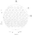
- first vent holes 21 penetrating in the thickness direction are formed in the outer air deflector 2.
- the cross section of the first vent hole 21 can be round, oval, triangular or polygonal.
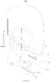
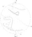
- the outer air deflector 2 can rotate between the first wind state (as shown in Figure 5 ) and the first open state (as shown in Figure 7 ).
- the outer air deflector 2 opens the air outlet 11 when in the first open state, closes the air outlet 11 when in the first wind state and is flush with the outer contour of the machine body.
- the indoor unit 100 when the outer air deflector 2 closes the air outlet 11 in the first wind state, the air flow in the body 1 can be blown from the first vent hole 21, the indoor unit 100 is in the first breeze mode at this moment, the outer air deflector 2 can stop the air flow to some extent, the air flow is only blown from the first vent hole 21, which can reduce the air speed and volume (nearly no wind) and achieve the no-wind effect.
- the indoor unit for air conditioner can effectively prevent air flow from blowing to people, thereby avoiding air-condition disease and achieving better user experience.
- the inner air deflector 3 is arranged at the air outlet 11 and inside the outer air deflector 2.
- the inner air deflector 3 can be arranged at the air outlet 11 in a rotating mode. When rotating to a certain angle, the inner air deflector 3 can guide the air flow to adjust the air outlet angle. Certainly, it can be understood that the inner air deflector 3 can rotate around the rotating shaft to swing the wind when the indoor unit 100 is working.
- the inner air deflector 3 can rotate between the second wind state (as shown in Figure 9 ) and the second open state (as shown in Figure 7 ).
- the inner air deflector 3 when the inner air deflector 3 is in the second open state, the inner air deflector 3 stretches into the air outlet 11 and is arranged in the air outlet direction (i.e., the inner air deflector 3 is roughly parallel to the air outlet direction).
- the indoor unit 100 is a wind mode, that is, the indoor unit 100 blows hot air or cool air directly, thereby adjusting the indoor temperature.
- the first vent hole 21 and the second vent hole 31 formed in the outer air deflector 2 and the inner air deflector 3 can reduce the air speed and volume of the air outlet 11 and achieve the effect of breeze or no wind.
- the indoor unit for air conditioner can switch various wind modes and improve the user experience.
- the sum of the area of the plurality of first vent holes 21 in the outer air deflector 2 is no less than 50% of its total area. Therefore, the indoor unit for air conditioner can not only reduce the outlet air speed and volume, but also can guarantee the cooling and heating effect of indoor environment.
- the total area of outer air deflector 2 comprises the area of the first vent hole 21.
- the first vent hole 21 can comprise the first hole section and the second hole section which are connected sequentially in the air outlet direction, wherein the outlet size of the first hole section is larger than the inlet size of the second hole section so that a parting surface is formed at the connection between the first hole section and the second hole section.
- the parting surface can further reduce the air speed and volume of air flow in the first vent hole 21, thereby further achieving the no-wind effect.
- the parting surface is also convenient for the forming of the first vent hole 21 and simplifying the structure.
- the first hole section of the first vent hole 21 retracts gradually in the air outlet direction, while the second hole section expands gradually in the air outlet direction.
- the hole diameter of the first hole section in the air outlet direction is reduced gradually, and the hole diameter of the second hole section is increased gradually. Therefore, the air volume of air flow in the first hole section can be reduced gradually, and the air speed of air flow in the second hole section can be reduced gradually, thereby achieving the no-wind effect.
- the parting surface can be a plane. Therefore, the parting surface can simplify the structure, facilitate machining and machining and reduce the air volume and speed.
- the inlet area of the first vent hole 21 is not larger than the outlet area, that is, the inlet area of the first vent hole 21 can be equal to the outlet area, and the inlet area of the first vent hole 21 can be smaller than the outlet area. Therefore, if the outlet air speed of the first vent hole 21 is lower than the inlet air speed, the air volume and speed can be reduced and, and no-wind mode can be realized.
- the inlet area of the first vent hole 21 can also be larger than the outlet area, so as to reduce outlet wind volume.
- the spacing between the parting surface of the first vent hole 21 and the outlet end is not more than half of its total length. Therefore, it is more favorable for achieving no-wind effect.
- the hole diameter of the first vent hole 21 is 2mm- 4mm, thereby effectively reducing the air speed and volume and guaranteeing the cooling and heating rate.
- the sum of the area of the plurality of second vent holes 31 in the inner air deflector 3 is no less than 50% of its total area. Therefore, the indoor unit for air conditioner can not only reduce the outlet air speed and volume, but also can guarantee the cooling and heating effect of indoor environment.
- the total area of inner air deflector 3 comprises the area of the second vent hole 31.
- the second vent hole 31 comprises the first hole section 311 and the second hole section 312 which are connected sequentially in the air outlet direction, wherein the outlet size of the first hole section 311 is smaller than the inlet size of the second hole section 312 so that the parting surface 313 can be formed at the connection between the first hole section 311 and the second hole section 312.
- the parting surface 313 can further reduce the air speed and volume of air flow in the second vent hole 31, thereby further achieving the no-wind effect.
- the parting surface 313 is also convenient for the forming of the second vent hole 31 and simplifying the structure.
- the inlet area of the second vent hole 31 is not larger than the outlet area, that is, the inlet area of the second vent hole 31 can be equal to the outlet area, and the inlet area of the second vent hole 31 can be smaller than the outlet area. Therefore, if the outlet air speed of the second vent hole 31 is lower than the inlet air speed, the air volume and speed can be reduced and, and no-wind mode can be realized.
- the spacing between the parting surface 313 of the second vent hole 31 and the outlet end is not more than half of its total length. Therefore, it is more favorable for achieving no-wind effect.
- the hole diameter of at least a part of the plurality of second vent holes 31 is reduced /increased sequentially from top to bottom or keeps unchanged. That is, the hole diameter of at least a part of the plurality of second vent holes 31 in the inner air deflector 3 can be reduced/increased sequentially from top to bottom, or the hole diameter can be the same, that is, keeping unchanged. Therefore, the hole diameters at different positions of inner air deflector 3 can be set according to the air outlet requirement, thereby improving the applicability.
- At least a part of the plurality of second vent holes 31 can be set along the preset straight line or curve sequentially. Therefore, the position of the second vent hole 31 can be set reasonably, and the appearance can be enhanced.
- the air speed and volume can be changed by changing the hole diameter of the second vent hole 31, which is favorable for achieving no-wind effect.
- the hole diameter of the second vent hole 31 is 4mm-8mm, thereby effectively reducing the air speed and volume and guaranteeing the cooling and heating rate.
- the included angle between the center line and horizontal plane of the second vent hole 31 is -10° to 10°.
- the included angle between the center line and horizontal plane of the second vent hole 31 is -5° to 5°.
- the center line of the second vent hole 31 is roughly parallel to the horizontal plane. Therefore, the air flow can be blown horizontally rather than to the human body direction, thereby improving the user experience.
- the indoor unit 100 in the embodiment of the present invention has no-wind mode, first breeze mode, second breeze mode, cooling wind mode and heating wind mode.
- first breeze mode first breeze mode
- second breeze mode cooling wind mode
- heating wind mode heating wind mode
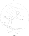
- the inner air deflector 3 When in the first breeze mode, the inner air deflector 3 is rotated to the position perpendicular to the air speed, the wind in the body 1 is blown from the plurality of second vent holes 31, and the air speed is reduced. However, since the hole diameter of the second vent holes 31 is larger (the hole diameter of the second vent hole 31 is larger than the hole diameter of the first vent hole 21), there is breeze still, as shown in Figure 9 .
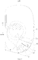
- the outer air deflector 2 When in the no-wind mode, the outer air deflector 2 is rotated to the closing state, the inner air deflector 3 is rotated till it is perpendicular to the air speed, the wind in the body 1 is blown from the plurality of second vent holes 31 and the plurality of first vent holes 21 sequentially, thereby reducing the air speed and volume and achieving the no-wind effect, as shown in Figure 2 .
- first and second are used only for the description, rather than indicating or implying relative importance or stating implicitly the quantity of the indicated technological features. Therefore a feature defined as “first” and “second” may, explicitly or implicitly, comprise one or more such features. Unless otherwise stated, "a plurality of” means two or more in the description of the present invention.
- connection shall be understood generally, for example, it may be fixed connection, detachable connection, or integral connection; or mechanical or electrical connections; or direct linking, indirect linking through an intermediate medium, or internal connection or interaction of two components.
- installation shall be understood generally, for example, it may be fixed connection, detachable connection, or integral connection; or mechanical or electrical connections; or direct linking, indirect linking through an intermediate medium, or internal connection or interaction of two components.
- specific meaning of the above terms in the present disclosure may be understood on a case by case basis by common technicians in the field.
Landscapes
- Engineering & Computer Science (AREA)
- Chemical & Material Sciences (AREA)
- Combustion & Propulsion (AREA)
- Mechanical Engineering (AREA)
- General Engineering & Computer Science (AREA)
- Air-Flow Control Members (AREA)
- Air Filters, Heat-Exchange Apparatuses, And Housings Of Air-Conditioning Units (AREA)
- Devices For Blowing Cold Air, Devices For Blowing Warm Air, And Means For Preventing Water Condensation In Air Conditioning Units (AREA)
Claims (13)
- Inneneinheit (100) für eine Klimaanlage, die Folgendes umfasst:einen Körper (1), der mit einem Luftauslass (11) versehen ist;ein äußeres Luftablenkelement (2), das an dem Luftauslass angeordnet ist und dazu konfiguriert ist, den Luftauslass zu öffnen und zu schließen; undein inneres Luftablenkelement (3), das an dem Luftauslass und innerhalb des äußeren Luftablenkelements angeordnet ist, wobei das innere Luftablenkelement mit einer Vielzahl von zweiten Luftlöchern (31) gebildet ist, die das innere Luftablenkelement in der Dickenrichtung durchdringen,dadurch gekennzeichnet, dass:das äußere Luftablenkelement (2) mit einer Vielzahl von ersten Luftlöchern (21) gebildet ist, die das äußere Luftablenkelement in einer Dickenrichtung durchdringen,wobei ein beliebiges der ersten Luftlöcher und der zweiten Luftlöcher einen ersten Lochabschnitt (311) und einen zweiten Lochabschnitt (312) umfasst, die in einer Luftauslassrichtung aufeinanderfolgend verbunden sind, und wobei eine Auslassgröße des ersten Lochabschnitts größer als eine Einlassgröße des zweiten Lochabschnitts ist, um eine Trennfläche (313) zu bilden.
- Inneneinheit nach Anspruch 1, wobei sich der erste Lochabschnitt in der Luftauslassrichtung allmählich verengt, während sich der zweite Lochabschnitt in der Luftauslassrichtung allmählich aufweitet.
- Inneneinheit nach Anspruch 1, wobei es sich bei der Trennfläche um eine Ebene handelt.
- Inneneinheit nach einem der vorangehenden Ansprüche, wobei ein Abstand zwischen einer Trennfläche und einem Auslassende des ersten Luftlochs nicht mehr als die Hälfte einer Gesamtlänge des ersten Luftlochs beträgt, und/oder ein Abstand zwischen einer Trennfläche und einem Auslass des zweiten Luftlochs nicht mehr als die Hälfte einer Gesamtlänge des zweiten Luftlochs beträgt.
- Inneneinheit nach einem der vorangehenden Ansprüche, wobei Lochdurchmesser von mindestens einem Teil der Vielzahl von ersten Luftlöchern aufeinanderfolgend von oben nach unten verringert oder vergrößert sind, und/oder Lochdurchmesser von mindestens einem Teil der Vielzahl von zweiten Luftlöchern aufeinanderfolgend von oben nach unten verringert oder vergrößert sind.
- Inneneinheit nach einem der vorangehenden Ansprüche, wobei mindestens ein Teil der Vielzahl von ersten Luftlöchern aufeinanderfolgend entlang einer vorgebebenen Geraden oder Kurve angeordnet sind, und/oder mindestens ein Teil der Vielzahl von zweiten Luftlöchern entlang einer vorgegebenen Geraden oder Kurve angeordnet sind.
- Inneneinheit nach einem der vorangehenden Ansprüche, wobei:der Lochdurchmesser des ersten Luftlochs in einem Bereich von 2 mm bis 4 mm liegt und/oder der Lochdurchmesser des zweiten Luftlochs in einem Bereich von 4 mm bis 8 mm liegt; undein eingeschlossener Winkel zwischen einer Mittelachse des ersten Luftlochs und der Horizontalebene im Bereich von -10° bis 10° liegt, wenn das äußere Luftablenkelement zu der Luftauslassrichtung senkrecht ist, und/oder ein eingeschlossener Winkel zwischen einer Mittelachse des zweiten Luftlochs und der Horizontal ebene im Bereich von -10° bis 10° liegt, wenn das innere Luftablenkelement zu der Luftauslassrichtung senkrecht ist.
- Inneneinheit nach einem der vorangehenden Ansprüche, wobei ein Gesamtflächeninhalt des inneren Luftablenkelements nicht weniger als 45 % eines Flächeninhalts des Luftauslasses beträgt.
- Inneneinheit nach einem der vorangehenden Ansprüche, wobei die Summe der Flächeninhalte der Vielzahl von zweiten Luftlöchern in dem inneren Luftablenkelement nicht weniger als 50 % eines Gesamtflächeninhalts des inneren Luftablenkelements beträgt.
- Inneneinheit nach einem der vorangehenden Ansprüche, wobei ein Projektionsflächeninhalt des inneren Luftablenkelements entlang einer Dickenrichtung davon nicht weniger als 70 % eines Gesamtflächeninhalts des Luftauslasses beträgt.
- Inneneinheit nach einem der vorangehenden Ansprüche, wobei das äußere Luftablenkelement zwischen einem ersten Luftzugzustand und einem ersten offenen Zustand drehbar ist und das äußere Luftablenkelement den Luftauslass öffnet, wenn es sich in dem ersten offenen Zustand befindet, und den Luftauslass schließt, wenn es sich in dem ersten Luftzugzustand befindet.
- Inneneinheit nach einem der vorangehenden Ansprüche, wobei das innere Luftablenkelement zwischen einem zweiten Luftzugzustand und einem zweiten offenen Zustand drehbar ist, sich das innere Luftablenkelement in den Luftauslass erstreckt und entlang der Luftauslassrichtung angeordnet ist, wenn es sich in dem zweiten offenen Zustand befindet, und das innere Luftablenkelement mit einer Außenkontur des Körpers bündig ist, wenn es sich in dem zweiten Luftzugzustand befindet.
- Inneneinheit nach einem der vorangehenden Ansprüche, wobei ein beliebiges der ersten Luftlöcher und der zweiten Luftlöcher einen runden, ovalen, dreieckigen oder vieleckigen Querschnitt aufweist.
Applications Claiming Priority (3)
| Application Number | Priority Date | Filing Date | Title |
|---|---|---|---|
| CN201720949029.3U CN207146545U (zh) | 2017-07-31 | 2017-07-31 | 空调室内机 |
| CN201710642312.6A CN107401776A (zh) | 2017-07-31 | 2017-07-31 | 空调室内机 |
| PCT/CN2018/084927 WO2019024550A1 (zh) | 2017-07-31 | 2018-04-27 | 空调室内机 |
Publications (3)
| Publication Number | Publication Date |
|---|---|
| EP3604935A1 EP3604935A1 (de) | 2020-02-05 |
| EP3604935A4 EP3604935A4 (de) | 2020-04-15 |
| EP3604935B1 true EP3604935B1 (de) | 2023-01-11 |
Family
ID=65232521
Family Applications (1)
| Application Number | Title | Priority Date | Filing Date |
|---|---|---|---|
| EP18841965.9A Active EP3604935B1 (de) | 2017-07-31 | 2018-04-27 | Innenraumklimatisierungseinheit |
Country Status (7)
| Country | Link |
|---|---|
| US (1) | US11982450B2 (de) |
| EP (1) | EP3604935B1 (de) |
| JP (1) | JP6965365B2 (de) |
| KR (2) | KR20200022497A (de) |
| AU (1) | AU2018311608B2 (de) |
| ES (1) | ES2939714T3 (de) |
| WO (1) | WO2019024550A1 (de) |
Families Citing this family (5)
| Publication number | Priority date | Publication date | Assignee | Title |
|---|---|---|---|---|
| EP3851755B1 (de) * | 2018-09-30 | 2022-09-21 | GD Midea Air-Conditioning Equipment Co., Ltd. | Steuerungsverfahren für klimaanlageninnenraumeinheit |
| JP7584232B2 (ja) * | 2020-04-06 | 2024-11-15 | 三菱重工サーマルシステムズ株式会社 | 空調装置 |
| JP7442412B2 (ja) * | 2020-08-25 | 2024-03-04 | 東芝ライフスタイル株式会社 | 空気調和機 |
| CN112460782B (zh) * | 2020-11-16 | 2021-12-03 | 珠海格力电器股份有限公司 | 防护件、面板组件和空调器 |
| WO2024237476A1 (ko) * | 2023-05-17 | 2024-11-21 | 삼성전자주식회사 | 공기조화기의 실내기 |
Family Cites Families (46)
| Publication number | Priority date | Publication date | Assignee | Title |
|---|---|---|---|---|
| JP3302906B2 (ja) * | 1997-07-15 | 2002-07-15 | 三菱電機株式会社 | 空気調和装置 |
| JP3748046B2 (ja) | 2001-03-02 | 2006-02-22 | シャープ株式会社 | 空気調和機 |
| JP2002277038A (ja) | 2001-03-19 | 2002-09-25 | Yoshihiro Kobayashi | 風向風量調整用器具 |
| JP2004101072A (ja) * | 2002-09-10 | 2004-04-02 | Sharp Corp | 空気調和機 |
| JP2004177097A (ja) | 2002-11-28 | 2004-06-24 | Tornex Inc | 流体吐出方向制御装置 |
| CN2731543Y (zh) | 2004-08-23 | 2005-10-05 | 联想(北京)有限公司 | 带有导风流道侧板的机箱 |
| KR20080060845A (ko) | 2006-12-27 | 2008-07-02 | 엘지전자 주식회사 | 공기조화기 실내기 |
| KR200454962Y1 (ko) * | 2009-02-28 | 2011-08-22 | 송창열 | 에어컨 실외기 난간대 및 거치대와, 이에 사용되는 통기성 돌기판넬 |
| JP5279622B2 (ja) * | 2009-06-08 | 2013-09-04 | 三菱電機株式会社 | 空気調和機の室内機 |
| SE536395C2 (sv) * | 2010-05-31 | 2013-10-08 | Suncore Ab I Konkurs | Anordning och system för klimatstyrning |
| CN102252407A (zh) | 2011-08-01 | 2011-11-23 | 广东美的制冷设备有限公司 | 空调器室内机的导风装置 |
| CN202254163U (zh) | 2011-09-15 | 2012-05-30 | 广州约顿电子科技有限公司 | 一种送风板 |
| KR101916994B1 (ko) * | 2013-05-21 | 2018-11-08 | 캐나다 파이프라인 액세서리스, 코. 엘티디. | 유량정류장치 및 그의 설계 방법 |
| CN203375639U (zh) * | 2013-06-20 | 2014-01-01 | 广东美的制冷设备有限公司 | 出风口导风结构及空调器 |
| KR101352653B1 (ko) * | 2013-09-26 | 2014-01-16 | 이광훈 | 에어 무버 |
| CN203642435U (zh) | 2013-11-27 | 2014-06-11 | 海尔集团公司 | 一种空调及其导风装置 |
| CN107023977B (zh) | 2013-11-27 | 2019-03-01 | 海尔集团公司 | 一种空调及其导风装置 |
| CN104676864B (zh) | 2013-11-27 | 2018-05-08 | 海尔集团公司 | 一种空调及其导风装置和方法 |
| JP2015206495A (ja) * | 2014-04-17 | 2015-11-19 | 日立アプライアンス株式会社 | 空気調和機 |
| JP6129126B2 (ja) * | 2014-08-04 | 2017-05-17 | 三菱電機株式会社 | 空気調和機の室内機 |
| CN104697055B (zh) * | 2015-02-13 | 2017-06-27 | 广东美的制冷设备有限公司 | 空调室内机及空调室内机的控制方法 |
| CN204555022U (zh) * | 2015-02-13 | 2015-08-12 | 广东美的制冷设备有限公司 | 空调室内机 |
| CN204555023U (zh) * | 2015-02-13 | 2015-08-12 | 广东美的制冷设备有限公司 | 空调室内机 |
| CN104676758A (zh) | 2015-02-13 | 2015-06-03 | 广东美的制冷设备有限公司 | 空调器室内机和挡风板 |
| CN204786798U (zh) * | 2015-02-13 | 2015-11-18 | 广东美的制冷设备有限公司 | 空调室内机 |
| CN104697056B (zh) * | 2015-02-13 | 2017-06-27 | 广东美的制冷设备有限公司 | 空调室内机及其控制方法 |
| CN104697058B (zh) * | 2015-02-13 | 2017-06-27 | 广东美的制冷设备有限公司 | 空调室内机及其控制方法 |
| CN106152270B (zh) | 2015-04-28 | 2022-03-22 | 广东美的制冷设备有限公司 | 空调器壳体和具有其的空调器 |
| CN104913444B (zh) * | 2015-05-29 | 2018-04-27 | 广东美的制冷设备有限公司 | 空调器及其的风速控制方法 |
| CN204962964U (zh) * | 2015-08-07 | 2016-01-13 | 广东美的制冷设备有限公司 | 空调室内机及空调器 |
| CN105180268B (zh) * | 2015-08-07 | 2017-10-27 | 广东美的制冷设备有限公司 | 空调室内机及空调室内出风控制方法 |
| CN204901976U (zh) * | 2015-08-07 | 2015-12-23 | 广东美的制冷设备有限公司 | 空调室内机及空调器 |
| CN204987237U (zh) * | 2015-08-07 | 2016-01-20 | 广东美的制冷设备有限公司 | 空调室内机及空调器 |
| CN105135519B (zh) | 2015-08-07 | 2017-09-29 | 广东美的制冷设备有限公司 | 空调室内机及空调室内出风控制方法 |
| CN105176046A (zh) * | 2015-10-23 | 2015-12-23 | 珠海格力电器股份有限公司 | 一种改性pc-abs合金塑料及其制备方法 |
| CN105444266B (zh) * | 2015-12-10 | 2018-12-14 | 珠海格力电器股份有限公司 | 空调室内机 |
| CN105444387B (zh) * | 2015-12-29 | 2018-06-19 | 美的集团武汉制冷设备有限公司 | 出风调节板及空调室内机 |
| CN105423521B (zh) * | 2015-12-31 | 2018-12-25 | 广东美的制冷设备有限公司 | 空调柜机及空调器 |
| CN106123120B (zh) * | 2016-07-01 | 2019-03-29 | 芜湖美智空调设备有限公司 | 一种空调器室内机控制方法 |
| CN206018823U (zh) * | 2016-08-24 | 2017-03-15 | 珠海格力电器股份有限公司 | 空调器及其空调室内机 |
| EP4596980A3 (de) * | 2016-12-21 | 2025-10-15 | Samsung Electronics Co., Ltd. | Klimaanlage |
| CN106839119A (zh) * | 2017-03-17 | 2017-06-13 | 广东美的制冷设备有限公司 | 空调室内机及空调器 |
| CN106949615B (zh) | 2017-03-17 | 2019-06-07 | 珠海格力电器股份有限公司 | 出风结构、空调器的出风方法和空调器 |
| CN106958864B (zh) * | 2017-04-13 | 2019-10-01 | 青岛海尔空调器有限总公司 | 空调室内壁挂机及其控制方法 |
| CN207146545U (zh) | 2017-07-31 | 2018-03-27 | 广东美的制冷设备有限公司 | 空调室内机 |
| CN108759052A (zh) * | 2017-07-31 | 2018-11-06 | 广东美的制冷设备有限公司 | 导风板组件、空调室内机和空调室内机的控制方法 |
-
2018
- 2018-04-27 ES ES18841965T patent/ES2939714T3/es active Active
- 2018-04-27 AU AU2018311608A patent/AU2018311608B2/en active Active
- 2018-04-27 KR KR1020207003388A patent/KR20200022497A/ko not_active Ceased
- 2018-04-27 EP EP18841965.9A patent/EP3604935B1/de active Active
- 2018-04-27 JP JP2019557422A patent/JP6965365B2/ja active Active
- 2018-04-27 WO PCT/CN2018/084927 patent/WO2019024550A1/zh not_active Ceased
- 2018-04-27 KR KR1020237004656A patent/KR102569423B1/ko active Active
-
2020
- 2020-01-30 US US16/776,816 patent/US11982450B2/en active Active
Also Published As
| Publication number | Publication date |
|---|---|
| AU2018311608A1 (en) | 2020-03-12 |
| BR112020006318A2 (pt) | 2020-09-29 |
| KR20230023069A (ko) | 2023-02-16 |
| US11982450B2 (en) | 2024-05-14 |
| WO2019024550A1 (zh) | 2019-02-07 |
| KR20200022497A (ko) | 2020-03-03 |
| JP2020517889A (ja) | 2020-06-18 |
| KR102569423B1 (ko) | 2023-08-21 |
| ES2939714T3 (es) | 2023-04-26 |
| EP3604935A1 (de) | 2020-02-05 |
| AU2018311608B2 (en) | 2021-04-01 |
| EP3604935A4 (de) | 2020-04-15 |
| JP6965365B2 (ja) | 2021-11-10 |
| US20200166223A1 (en) | 2020-05-28 |
Similar Documents
| Publication | Publication Date | Title |
|---|---|---|
| CN108731106B (zh) | 空调室内机和空调器 | |
| CN107449038B (zh) | 空调室内机 | |
| CN111271772B (zh) | 空调室内机 | |
| US11982450B2 (en) | Air conditioner indoor unit | |
| CN106839119A (zh) | 空调室内机及空调器 | |
| US11913650B2 (en) | Air conditioner indoor unit | |
| EP3604941A1 (de) | Klimaanlage und steuerungsverfahren dafür | |
| CN206626676U (zh) | 空调室内机及空调器 | |
| CN209877308U (zh) | 空调室内机的导风板组件及空调室内机 | |
| AU2018311609B2 (en) | Indoor air-conditioning unit | |
| KR20030022918A (ko) | 토출면적 조절형 공기조화기 및 그 동작방법 |
Legal Events
| Date | Code | Title | Description |
|---|---|---|---|
| STAA | Information on the status of an ep patent application or granted ep patent |
Free format text: STATUS: THE INTERNATIONAL PUBLICATION HAS BEEN MADE |
|
| PUAI | Public reference made under article 153(3) epc to a published international application that has entered the european phase |
Free format text: ORIGINAL CODE: 0009012 |
|
| STAA | Information on the status of an ep patent application or granted ep patent |
Free format text: STATUS: REQUEST FOR EXAMINATION WAS MADE |
|
| 17P | Request for examination filed |
Effective date: 20191024 |
|
| AK | Designated contracting states |
Kind code of ref document: A1 Designated state(s): AL AT BE BG CH CY CZ DE DK EE ES FI FR GB GR HR HU IE IS IT LI LT LU LV MC MK MT NL NO PL PT RO RS SE SI SK SM TR |
|
| AX | Request for extension of the european patent |
Extension state: BA ME |
|
| RAP1 | Party data changed (applicant data changed or rights of an application transferred) |
Owner name: GD MIDEA AIR-CONDITIONING EQUIPMENT CO., LTD. |
|
| A4 | Supplementary search report drawn up and despatched |
Effective date: 20200312 |
|
| RIC1 | Information provided on ipc code assigned before grant |
Ipc: F24F 1/0011 20190101ALI20200306BHEP Ipc: F24F 13/10 20060101ALI20200306BHEP Ipc: F24F 13/14 20060101ALI20200306BHEP Ipc: F24F 1/00 20190101AFI20200306BHEP |
|
| DAV | Request for validation of the european patent (deleted) | ||
| DAX | Request for extension of the european patent (deleted) | ||
| RAP3 | Party data changed (applicant data changed or rights of an application transferred) |
Owner name: GD MIDEA AIR-CONDITIONING EQUIPMENT CO., LTD. |
|
| GRAP | Despatch of communication of intention to grant a patent |
Free format text: ORIGINAL CODE: EPIDOSNIGR1 |
|
| STAA | Information on the status of an ep patent application or granted ep patent |
Free format text: STATUS: GRANT OF PATENT IS INTENDED |
|
| INTG | Intention to grant announced |
Effective date: 20221020 |
|
| GRAS | Grant fee paid |
Free format text: ORIGINAL CODE: EPIDOSNIGR3 |
|
| GRAA | (expected) grant |
Free format text: ORIGINAL CODE: 0009210 |
|
| STAA | Information on the status of an ep patent application or granted ep patent |
Free format text: STATUS: THE PATENT HAS BEEN GRANTED |
|
| AK | Designated contracting states |
Kind code of ref document: B1 Designated state(s): AL AT BE BG CH CY CZ DE DK EE ES FI FR GB GR HR HU IE IS IT LI LT LU LV MC MK MT NL NO PL PT RO RS SE SI SK SM TR |
|
| REG | Reference to a national code |
Ref country code: GB Ref legal event code: FG4D |
|
| REG | Reference to a national code |
Ref country code: CH Ref legal event code: EP |
|
| REG | Reference to a national code |
Ref country code: DE Ref legal event code: R096 Ref document number: 602018045387 Country of ref document: DE |
|
| REG | Reference to a national code |
Ref country code: IE Ref legal event code: FG4D |
|
| REG | Reference to a national code |
Ref country code: AT Ref legal event code: REF Ref document number: 1543654 Country of ref document: AT Kind code of ref document: T Effective date: 20230215 |
|
| REG | Reference to a national code |
Ref country code: ES Ref legal event code: FG2A Ref document number: 2939714 Country of ref document: ES Kind code of ref document: T3 Effective date: 20230426 |
|
| REG | Reference to a national code |
Ref country code: LT Ref legal event code: MG9D |
|
| REG | Reference to a national code |
Ref country code: NL Ref legal event code: MP Effective date: 20230111 |
|
| REG | Reference to a national code |
Ref country code: AT Ref legal event code: MK05 Ref document number: 1543654 Country of ref document: AT Kind code of ref document: T Effective date: 20230111 |
|
| PG25 | Lapsed in a contracting state [announced via postgrant information from national office to epo] |
Ref country code: NL Free format text: LAPSE BECAUSE OF FAILURE TO SUBMIT A TRANSLATION OF THE DESCRIPTION OR TO PAY THE FEE WITHIN THE PRESCRIBED TIME-LIMIT Effective date: 20230111 |
|
| P01 | Opt-out of the competence of the unified patent court (upc) registered |
Effective date: 20230526 |
|
| PG25 | Lapsed in a contracting state [announced via postgrant information from national office to epo] |
Ref country code: RS Free format text: LAPSE BECAUSE OF FAILURE TO SUBMIT A TRANSLATION OF THE DESCRIPTION OR TO PAY THE FEE WITHIN THE PRESCRIBED TIME-LIMIT Effective date: 20230111 Ref country code: PT Free format text: LAPSE BECAUSE OF FAILURE TO SUBMIT A TRANSLATION OF THE DESCRIPTION OR TO PAY THE FEE WITHIN THE PRESCRIBED TIME-LIMIT Effective date: 20230511 Ref country code: NO Free format text: LAPSE BECAUSE OF FAILURE TO SUBMIT A TRANSLATION OF THE DESCRIPTION OR TO PAY THE FEE WITHIN THE PRESCRIBED TIME-LIMIT Effective date: 20230411 Ref country code: LV Free format text: LAPSE BECAUSE OF FAILURE TO SUBMIT A TRANSLATION OF THE DESCRIPTION OR TO PAY THE FEE WITHIN THE PRESCRIBED TIME-LIMIT Effective date: 20230111 Ref country code: LT Free format text: LAPSE BECAUSE OF FAILURE TO SUBMIT A TRANSLATION OF THE DESCRIPTION OR TO PAY THE FEE WITHIN THE PRESCRIBED TIME-LIMIT Effective date: 20230111 Ref country code: HR Free format text: LAPSE BECAUSE OF FAILURE TO SUBMIT A TRANSLATION OF THE DESCRIPTION OR TO PAY THE FEE WITHIN THE PRESCRIBED TIME-LIMIT Effective date: 20230111 Ref country code: AT Free format text: LAPSE BECAUSE OF FAILURE TO SUBMIT A TRANSLATION OF THE DESCRIPTION OR TO PAY THE FEE WITHIN THE PRESCRIBED TIME-LIMIT Effective date: 20230111 |
|
| PG25 | Lapsed in a contracting state [announced via postgrant information from national office to epo] |
Ref country code: SE Free format text: LAPSE BECAUSE OF FAILURE TO SUBMIT A TRANSLATION OF THE DESCRIPTION OR TO PAY THE FEE WITHIN THE PRESCRIBED TIME-LIMIT Effective date: 20230111 Ref country code: PL Free format text: LAPSE BECAUSE OF FAILURE TO SUBMIT A TRANSLATION OF THE DESCRIPTION OR TO PAY THE FEE WITHIN THE PRESCRIBED TIME-LIMIT Effective date: 20230111 Ref country code: IS Free format text: LAPSE BECAUSE OF FAILURE TO SUBMIT A TRANSLATION OF THE DESCRIPTION OR TO PAY THE FEE WITHIN THE PRESCRIBED TIME-LIMIT Effective date: 20230511 Ref country code: GR Free format text: LAPSE BECAUSE OF FAILURE TO SUBMIT A TRANSLATION OF THE DESCRIPTION OR TO PAY THE FEE WITHIN THE PRESCRIBED TIME-LIMIT Effective date: 20230412 Ref country code: FI Free format text: LAPSE BECAUSE OF FAILURE TO SUBMIT A TRANSLATION OF THE DESCRIPTION OR TO PAY THE FEE WITHIN THE PRESCRIBED TIME-LIMIT Effective date: 20230111 |
|
| REG | Reference to a national code |
Ref country code: DE Ref legal event code: R097 Ref document number: 602018045387 Country of ref document: DE |
|
| PG25 | Lapsed in a contracting state [announced via postgrant information from national office to epo] |
Ref country code: SM Free format text: LAPSE BECAUSE OF FAILURE TO SUBMIT A TRANSLATION OF THE DESCRIPTION OR TO PAY THE FEE WITHIN THE PRESCRIBED TIME-LIMIT Effective date: 20230111 Ref country code: RO Free format text: LAPSE BECAUSE OF FAILURE TO SUBMIT A TRANSLATION OF THE DESCRIPTION OR TO PAY THE FEE WITHIN THE PRESCRIBED TIME-LIMIT Effective date: 20230111 Ref country code: EE Free format text: LAPSE BECAUSE OF FAILURE TO SUBMIT A TRANSLATION OF THE DESCRIPTION OR TO PAY THE FEE WITHIN THE PRESCRIBED TIME-LIMIT Effective date: 20230111 Ref country code: DK Free format text: LAPSE BECAUSE OF FAILURE TO SUBMIT A TRANSLATION OF THE DESCRIPTION OR TO PAY THE FEE WITHIN THE PRESCRIBED TIME-LIMIT Effective date: 20230111 Ref country code: CZ Free format text: LAPSE BECAUSE OF FAILURE TO SUBMIT A TRANSLATION OF THE DESCRIPTION OR TO PAY THE FEE WITHIN THE PRESCRIBED TIME-LIMIT Effective date: 20230111 |
|
| REG | Reference to a national code |
Ref country code: DE Ref legal event code: R119 Ref document number: 602018045387 Country of ref document: DE |
|
| PLBE | No opposition filed within time limit |
Free format text: ORIGINAL CODE: 0009261 |
|
| STAA | Information on the status of an ep patent application or granted ep patent |
Free format text: STATUS: NO OPPOSITION FILED WITHIN TIME LIMIT |
|
| PG25 | Lapsed in a contracting state [announced via postgrant information from national office to epo] |
Ref country code: SK Free format text: LAPSE BECAUSE OF FAILURE TO SUBMIT A TRANSLATION OF THE DESCRIPTION OR TO PAY THE FEE WITHIN THE PRESCRIBED TIME-LIMIT Effective date: 20230111 |
|
| REG | Reference to a national code |
Ref country code: CH Ref legal event code: PL |
|
| 26N | No opposition filed |
Effective date: 20231012 |
|
| GBPC | Gb: european patent ceased through non-payment of renewal fee |
Effective date: 20230427 |
|
| PG25 | Lapsed in a contracting state [announced via postgrant information from national office to epo] |
Ref country code: LU Free format text: LAPSE BECAUSE OF NON-PAYMENT OF DUE FEES Effective date: 20230427 |
|
| REG | Reference to a national code |
Ref country code: BE Ref legal event code: MM Effective date: 20230430 |
|
| PG25 | Lapsed in a contracting state [announced via postgrant information from national office to epo] |
Ref country code: MC Free format text: LAPSE BECAUSE OF FAILURE TO SUBMIT A TRANSLATION OF THE DESCRIPTION OR TO PAY THE FEE WITHIN THE PRESCRIBED TIME-LIMIT Effective date: 20230111 |
|
| PG25 | Lapsed in a contracting state [announced via postgrant information from national office to epo] |
Ref country code: GB Free format text: LAPSE BECAUSE OF NON-PAYMENT OF DUE FEES Effective date: 20230427 |
|
| PG25 | Lapsed in a contracting state [announced via postgrant information from national office to epo] |
Ref country code: SI Free format text: LAPSE BECAUSE OF FAILURE TO SUBMIT A TRANSLATION OF THE DESCRIPTION OR TO PAY THE FEE WITHIN THE PRESCRIBED TIME-LIMIT Effective date: 20230111 Ref country code: MC Free format text: LAPSE BECAUSE OF FAILURE TO SUBMIT A TRANSLATION OF THE DESCRIPTION OR TO PAY THE FEE WITHIN THE PRESCRIBED TIME-LIMIT Effective date: 20230111 Ref country code: LI Free format text: LAPSE BECAUSE OF NON-PAYMENT OF DUE FEES Effective date: 20230430 Ref country code: GB Free format text: LAPSE BECAUSE OF NON-PAYMENT OF DUE FEES Effective date: 20230427 Ref country code: DE Free format text: LAPSE BECAUSE OF NON-PAYMENT OF DUE FEES Effective date: 20231103 Ref country code: CH Free format text: LAPSE BECAUSE OF NON-PAYMENT OF DUE FEES Effective date: 20230430 |
|
| REG | Reference to a national code |
Ref country code: IE Ref legal event code: MM4A |
|
| PG25 | Lapsed in a contracting state [announced via postgrant information from national office to epo] |
Ref country code: BE Free format text: LAPSE BECAUSE OF NON-PAYMENT OF DUE FEES Effective date: 20230430 |
|
| PG25 | Lapsed in a contracting state [announced via postgrant information from national office to epo] |
Ref country code: IE Free format text: LAPSE BECAUSE OF NON-PAYMENT OF DUE FEES Effective date: 20230427 |
|
| PG25 | Lapsed in a contracting state [announced via postgrant information from national office to epo] |
Ref country code: IE Free format text: LAPSE BECAUSE OF NON-PAYMENT OF DUE FEES Effective date: 20230427 |
|
| PG25 | Lapsed in a contracting state [announced via postgrant information from national office to epo] |
Ref country code: BG Free format text: LAPSE BECAUSE OF FAILURE TO SUBMIT A TRANSLATION OF THE DESCRIPTION OR TO PAY THE FEE WITHIN THE PRESCRIBED TIME-LIMIT Effective date: 20230111 |
|
| PG25 | Lapsed in a contracting state [announced via postgrant information from national office to epo] |
Ref country code: BG Free format text: LAPSE BECAUSE OF FAILURE TO SUBMIT A TRANSLATION OF THE DESCRIPTION OR TO PAY THE FEE WITHIN THE PRESCRIBED TIME-LIMIT Effective date: 20230111 |
|
| PGFP | Annual fee paid to national office [announced via postgrant information from national office to epo] |
Ref country code: ES Payment date: 20250506 Year of fee payment: 8 |
|
| PGFP | Annual fee paid to national office [announced via postgrant information from national office to epo] |
Ref country code: IT Payment date: 20250418 Year of fee payment: 8 |
|
| PGFP | Annual fee paid to national office [announced via postgrant information from national office to epo] |
Ref country code: FR Payment date: 20250430 Year of fee payment: 8 |
|
| PG25 | Lapsed in a contracting state [announced via postgrant information from national office to epo] |
Ref country code: CY Free format text: LAPSE BECAUSE OF FAILURE TO SUBMIT A TRANSLATION OF THE DESCRIPTION OR TO PAY THE FEE WITHIN THE PRESCRIBED TIME-LIMIT; INVALID AB INITIO Effective date: 20180427 |
|
| PG25 | Lapsed in a contracting state [announced via postgrant information from national office to epo] |
Ref country code: HU Free format text: LAPSE BECAUSE OF FAILURE TO SUBMIT A TRANSLATION OF THE DESCRIPTION OR TO PAY THE FEE WITHIN THE PRESCRIBED TIME-LIMIT; INVALID AB INITIO Effective date: 20180427 |
|
| PG25 | Lapsed in a contracting state [announced via postgrant information from national office to epo] |
Ref country code: TR Free format text: LAPSE BECAUSE OF FAILURE TO SUBMIT A TRANSLATION OF THE DESCRIPTION OR TO PAY THE FEE WITHIN THE PRESCRIBED TIME-LIMIT Effective date: 20230111 |