EP3603839B1 - Scherverfahren, schervorrichtung und scheranlage - Google Patents
Scherverfahren, schervorrichtung und scheranlage Download PDFInfo
- Publication number
- EP3603839B1 EP3603839B1 EP18775469.2A EP18775469A EP3603839B1 EP 3603839 B1 EP3603839 B1 EP 3603839B1 EP 18775469 A EP18775469 A EP 18775469A EP 3603839 B1 EP3603839 B1 EP 3603839B1
- Authority
- EP
- European Patent Office
- Prior art keywords
- workpiece
- clearance
- shearing
- blade
- upper blade
- Prior art date
- Legal status (The legal status is an assumption and is not a legal conclusion. Google has not performed a legal analysis and makes no representation as to the accuracy of the status listed.)
- Active
Links
Images







Classifications
-
- B—PERFORMING OPERATIONS; TRANSPORTING
- B21—MECHANICAL METAL-WORKING WITHOUT ESSENTIALLY REMOVING MATERIAL; PUNCHING METAL
- B21D—WORKING OR PROCESSING OF SHEET METAL OR METAL TUBES, RODS OR PROFILES WITHOUT ESSENTIALLY REMOVING MATERIAL; PUNCHING METAL
- B21D37/00—Tools as parts of machines covered by this subclass
- B21D37/08—Dies with different parts for several steps in a process
-
- B—PERFORMING OPERATIONS; TRANSPORTING
- B21—MECHANICAL METAL-WORKING WITHOUT ESSENTIALLY REMOVING MATERIAL; PUNCHING METAL
- B21D—WORKING OR PROCESSING OF SHEET METAL OR METAL TUBES, RODS OR PROFILES WITHOUT ESSENTIALLY REMOVING MATERIAL; PUNCHING METAL
- B21D28/00—Shaping by press-cutting; Perforating
- B21D28/24—Perforating, i.e. punching holes
- B21D28/34—Perforating tools; Die holders
-
- B—PERFORMING OPERATIONS; TRANSPORTING
- B21—MECHANICAL METAL-WORKING WITHOUT ESSENTIALLY REMOVING MATERIAL; PUNCHING METAL
- B21D—WORKING OR PROCESSING OF SHEET METAL OR METAL TUBES, RODS OR PROFILES WITHOUT ESSENTIALLY REMOVING MATERIAL; PUNCHING METAL
- B21D28/00—Shaping by press-cutting; Perforating
- B21D28/02—Punching blanks or articles with or without obtaining scrap; Notching
-
- B—PERFORMING OPERATIONS; TRANSPORTING
- B23—MACHINE TOOLS; METAL-WORKING NOT OTHERWISE PROVIDED FOR
- B23D—PLANING; SLOTTING; SHEARING; BROACHING; SAWING; FILING; SCRAPING; LIKE OPERATIONS FOR WORKING METAL BY REMOVING MATERIAL, NOT OTHERWISE PROVIDED FOR
- B23D15/00—Shearing machines or shearing devices cutting by blades which move parallel to themselves
- B23D15/04—Shearing machines or shearing devices cutting by blades which move parallel to themselves having only one moving blade
-
- B—PERFORMING OPERATIONS; TRANSPORTING
- B23—MACHINE TOOLS; METAL-WORKING NOT OTHERWISE PROVIDED FOR
- B23D—PLANING; SLOTTING; SHEARING; BROACHING; SAWING; FILING; SCRAPING; LIKE OPERATIONS FOR WORKING METAL BY REMOVING MATERIAL, NOT OTHERWISE PROVIDED FOR
- B23D35/00—Tools for shearing machines or shearing devices; Holders or chucks for shearing tools
- B23D35/005—Adjusting the position of the cutting members
-
- B—PERFORMING OPERATIONS; TRANSPORTING
- B26—HAND CUTTING TOOLS; CUTTING; SEVERING
- B26D—CUTTING; DETAILS COMMON TO MACHINES FOR PERFORATING, PUNCHING, CUTTING-OUT, STAMPING-OUT OR SEVERING
- B26D1/00—Cutting through work characterised by the nature or movement of the cutting member or particular materials not otherwise provided for; Apparatus or machines therefor; Cutting members therefor
- B26D1/01—Cutting through work characterised by the nature or movement of the cutting member or particular materials not otherwise provided for; Apparatus or machines therefor; Cutting members therefor involving a cutting member which does not travel with the work
-
- B—PERFORMING OPERATIONS; TRANSPORTING
- B26—HAND CUTTING TOOLS; CUTTING; SEVERING
- B26D—CUTTING; DETAILS COMMON TO MACHINES FOR PERFORATING, PUNCHING, CUTTING-OUT, STAMPING-OUT OR SEVERING
- B26D7/00—Details of apparatus for cutting, cutting-out, stamping-out, punching, perforating, or severing by means other than cutting
- B26D7/06—Arrangements for feeding or delivering work of other than sheet, web, or filamentary form
-
- B—PERFORMING OPERATIONS; TRANSPORTING
- B26—HAND CUTTING TOOLS; CUTTING; SEVERING
- B26D—CUTTING; DETAILS COMMON TO MACHINES FOR PERFORATING, PUNCHING, CUTTING-OUT, STAMPING-OUT OR SEVERING
- B26D7/00—Details of apparatus for cutting, cutting-out, stamping-out, punching, perforating, or severing by means other than cutting
- B26D7/26—Means for mounting or adjusting the cutting member; Means for adjusting the stroke of the cutting member
- B26D7/2628—Means for adjusting the position of the cutting member
-
- B—PERFORMING OPERATIONS; TRANSPORTING
- B26—HAND CUTTING TOOLS; CUTTING; SEVERING
- B26D—CUTTING; DETAILS COMMON TO MACHINES FOR PERFORATING, PUNCHING, CUTTING-OUT, STAMPING-OUT OR SEVERING
- B26D1/00—Cutting through work characterised by the nature or movement of the cutting member or particular materials not otherwise provided for; Apparatus or machines therefor; Cutting members therefor
- B26D1/0006—Cutting members therefor
- B26D2001/0066—Cutting members therefor having shearing means, e.g. shearing blades, abutting blades
Definitions
- the present invention relates to a shearing method, a shearing machine, and shearing equipment.
- Shearing is a process for manufacturing (e.g. cutting, blanking, punching, shaving, and trimming) metal components used for, for instance, automobiles, rail cars, building components, ships, and home electric appliances.
- the shearing is usually performed by pushing an upper blade toward a lower blade that is in contact with the component. At this time, the component is plastically deformed between the upper blade and the lower blade to be eventually cut.
- work-hardened part work-hardened part caused by the plastic deformation during the shearing remains on an end face of the component after being cut.
- the work-hardened part may sometimes be cracked.
- Patent Literature 1 discloses a technique for providing a sheared surface excellent in stretch-flangeability by appropriately setting a slant angle of a punching blade based on a numerical simulation.
- Patent Literature 2 discloses a technique for providing a sheared surface excellent in stretch-flangeability by gradually increasing a clearance with an increase in a distance from a dangerous region determined based on a simulation on stretch-flange cracks in subsequent step(s).
- a machine according to the preamble of claim 11 is known from JP H07 51919 A .
- an object of the invention is to provide a novel and improved shearing method, shearing machine, and shearing equipment capable of reducing influence of work-hardening on an end face of a component after being cut.
- the clearance is changed to be increased during a shearing process, so that the influence of work-hardening on an end face of a component after being cut can be reduced.
- Fig. 1 is a schematic cross section showing a shearing machine 1 according to an exemplary embodiment of the invention.
- the shearing machine 1 according to the exemplary embodiment includes a die 2, a punch 3, a holder 4, and an actuator 5a.
- the die 2 is provided with a lower blade 21 to be in contact with a lower side of a plate-shaped workpiece 6.
- the punch 3 is provided with an upper blade 31.
- the punch 3 is driven by a motor or a hydraulic device (not shown) to be capable of movement relative to the die 2 in a thickness direction (i.e. approaching/separating direction of the upper blade 31 and the lower blade 21) of the workpiece 6.
- the upper blade 31, which is initially located above the workpiece 6, is brought into contact with an upper side of the workpiece 6 as illustrated, and pushed against the workpiece 6.
- a fractured surface is created between the lower blade 21 and the upper blade 31, so that the workpiece 6 is cut off at a portion against which the punch 3 is pushed.
- the holder 4 is configured to be brought into contact with the upper side of the workpiece 6 so that the workpiece 6 is held between the holder 4 and the die 2.
- the actuator 5a is, for instance, a motor or a hydraulic device.
- the actuator 5a is connected to the die 2 and configured to move the die 2 in a surface direction of the workpiece 6 (i.e. in a direction orthogonal to the thickness direction of the workpiece 6).
- the lower blade 21 may alternatively be configured to move relative to the fixed upper blade 31, or the upper blade 31 and the lower blade 21 may be configured to move relative to each other.
- the upper blade 31 faces the lower blade 21 at a clearance C in the surface direction (a direction orthogonal to the approaching/separating direction of the upper blade 31) of the workpiece 6.
- the movement of the die 2 in the surface direction of the workpiece 6 caused by the actuator 5a displaces the lower blade 21 toward or away from the upper blade 31.
- the clearance C is reduced when the lower blade 21 moves toward the upper blade 31, and is enlarged when the lower blade 21 moves away from the upper blade 31.
- the actuator 5a increases the clearance C depending on the movement distance of the upper blade 31 after the upper blade 31 is in contact with the upper side of the workpiece 6 until the fractured surface is created in the workpiece 6.
- the actuator 5a moves the lower blade 21 away from the upper blade 31 depending on the movement distance of the upper blade 31 in the thickness direction of the workpiece 6.
- the actuator 5a thus functions as the clearance adjuster in the exemplary embodiment.
- the actuator 5a may be configured to continuously move the lower blade 21 away from the upper blade 31 depending on the movement distance of the upper blade 31, or, alternatively, may be configured to move the lower blade 21 away from the upper blade 31 in a stepwise manner depending on the movement distance of the upper blade 31.
- the actuator 5a may be configured to move the lower blade 21 away from the upper blade 31 by a predetermined distance at a single timing determined in accordance with the movement distance of the upper blade 31 in the thickness direction.
- Figs. 2A to 2C are schematic illustrations showing the operation of the shearing machine 1 shown in Fig. 1 and the behavior of the workpiece 6.
- Fig. 2A shows the upper blade 31 being in contact with the upper side of the workpiece 6.
- the clearance C is set at c 0 .
- a movement distance H (movement distance in the thickness direction of the workpiece 6) of the upper blade 31 at this time is defined as 0.
- the state shown in Fig. 2A corresponds to a (shear start) step of starting applying a shear force on the workpiece 6 with a clearance between action points in the surface direction orthogonal to the thickness direction of the workpiece 6 in the exemplary embodiment.
- Fig. 2B shows the upper blade 31 being further moved from the state shown in Fig. 2A to be pushed against the workpiece 6.
- the movement distance H of the upper blade 31 is defined as h 1 .
- the actuator 5a moves the die 2 after the state shown in Fig. 2A , so that the lower blade 21 is moved away from the upper blade 31 with an increase in the clearance C (from c 0 to c 1 ).
- the work-hardening of the material inside the workpiece 6 occurs in a region R 1B .
- the region R 1B is enlarged at the lower side of the workpiece 6.
- Fig. 2C shows the upper blade 31 being further moved from the state shown in Fig. 2B to be further deeply pushed against the workpiece 6.
- the movement distance H of the upper blade 31 is h 2 , which is larger than h 1 .
- a fractured surface 61 is created in the workpiece 6.
- the actuator 5a further moves the die 2 after the state shown in Fig. 2B , so that the lower blade 21 is moved further away from the upper blade 31 with an increase in the clearance C (from c 1 to c 2 ).
- the work-hardening of the material inside the workpiece 6 occurs in a region R 1C .
- the region R 1C is further enlarged at the lower side of the workpiece 6.
- the states shown in Figs. 2B and 2C correspond to steps subsequent to the shear start, which are a (shear end) step for applying the shear force until the fractured surface is created in the workpiece 6, and a step for increasing the clearance depending on a deformation of the workpiece 6 in the thickness direction until the fractured surface 61 is created in the workpiece 6 in the exemplary embodiment, respectively.
- the fractured surface 61 of the workpiece 6 intersects the region R 1C in which the work-hardening occurs. Accordingly, the region affected by the work-hardening remains in the end face of the workpiece 6 after being cut.
- the work-hardening occurs in a dispersed manner and in a wider region than in a typical arrangement. Accordingly, the end face of the workpiece 6 after being cut is less affected by the work-hardening in the exemplary embodiment than in a typical shearing machine.
- Figs. 3A to 3C are schematic illustrations comparable to Fig. 2A to 2C , showing an operation of a typical shearing machine and a behavior of the workpiece 6.
- the clearance C is fixed at c 2 (the same as the clearance C in Fig. 2C ) throughout the shearing process.
- the work-hardening of the material inside the workpiece 6 occurs in a region R 2A .
- the region R 2A is a region along a plane connecting the lower blade 21 and the upper blade 31.
- the work-hardening of the material inside the workpiece 6 occurs in a region R 2C .
- the region R 1C shown in Fig. 2C is further enlarged at the lower side of the workpiece 6, there is no such enlargement in the region R 2C shown in Fig. 3C .
- the region R 2C is a relatively narrow region extending along the plane connecting the lower blade 21 and the upper blade 31.
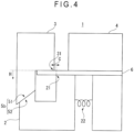
- Fig. 4 is a schematic cross section showing another example of a clearance adjuster according to an exemplary embodiment of the invention.
- the shearing machine 1 in this example includes a clearance adjuster in a form of a linear cam mechanism 5b.
- the linear cam mechanism 5b includes a first slant surface 51 formed on the punch 3 and a second slant surface 52 formed on the die 2.
- the first slant surface 51 is movable in the thickness direction of the workpiece 6 integrally with the upper blade 31 formed on the punch 3.
- the second slant surface 52 which is configured to be in slidable contact with the first slant surface 51, is movable in the surface direction of the workpiece 6 integrally with the lower blade 21 formed on the die 2.
- the shearing machine 1 further includes a spring 22 configured to bias the die 2 toward the punch 3 in the surface direction of the workpiece 6.
- the spring 22 serves as a clearance retainer configured to keep the clearance C when the first slant surface 51 is not in slidable contact with the second slant surface 52.
- the die 2 moves in the surface direction of the workpiece 6, so that the lower blade 21 starts moving away from the upper blade 31.
- the punch 3 continues movement in the thickness direction of the workpiece 6, in accordance with which the lower blade 21 continuously moves away from the upper blade 31.
- the linear cam mechanism 5b continuously moves the lower blade 21 away from the upper blade 31 depending on the movement distance of the upper blade 31 in the above example.
- the use of the clearance adjuster in a form of the linear cam mechanism 5b, which can change the clearance C using a drive force of the punch 3, allows, for instance, simplification of the equipment and increase in the process speed.
- the use of the clearance adjuster in a form of the above-described actuator 5a, which can change the clearance C independently of the drive of the punch 3, allows, for instance, adjustment of the change in the clearance C (e.g. change amount, change rate, start and end points of the change) as desired.
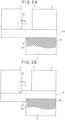
- Figs. 5A and 5B are schematic cross sections showing still another example of the clearance adjuster according to an exemplary embodiment of the invention.
- the clearance C is changed by forcibly moving the highly rigid die 2 provided with the lower blade 21 in a direction for changing the clearance by the linear cam mechanism 5b.
- the die 2 of the shearing machine 1 includes a die body 2a and an elastic body 5c, the lower blade 21 of the die body 2a with low rigidity being supported by the elastic body 5c to control a flexure of the lower blade 21 in a direction for changing the clearance ("clearance-changing direction").
- the elastic body 5c supports the die body 2a in a manner allowing a movement of the die body 2a in the clearance-changing direction.
- the die body 2a has a thin portion at an upper part (including the lower blade 21) whose thickness in the clearance-changing direction is smaller than other portions in the top-bottom direction.
- the elastic body 5c at least supports the thin portion of the die body 2a when the punch 3 is in contact with the workpiece 6.
- the die body 2a and the elastic body 5c are not necessarily bonded but may be separated when the shear force is not applied.
- the thickness of the thin portion may be different in the top-bottom direction.
- the dimensions in the top-bottom direction and in the clearance-changing direction of the elastic body 5c are determined based on, for instance, the location of the holder 4 and an elastic modulus of the elastic body 5c.
- the elastic body 5c is attached to a wall (not shown) or the like at a side opposite the die body 2a.
- the upper part of the lower blade 21, which receives a pushing force on the workpiece 6 in the surface direction, is elastically deformed in the clearance-changing direction.
- the elastic body 5c applies an elastic force, which resists the pushing force received by the lower blade 21 in a direction orthogonal to the surface direction of the workpiece 6, to the die body 2a including the lower blade 21.
- the elastically deformed upper part of the die body 2a gradually moves in the direction of the pushing force in the surface direction of the workpiece 6 while being supported by the elastically deformed elastic body 5c.
- the die body 2a does not necessarily have the thin portion.
- an entirety of the die body 2a is attached in a manner movable along the surface direction of the workpiece 6 and the elastic body 5c supports the die 2 in a manner allowing the movement of the die 2.
- the entirety of the die body 2a moves in the surface direction of the workpiece 6, so that the lower blade 21 gradually moves in the direction of the pushing force in the surface direction of the workpiece 6.
- the pushing force in the surface direction of the workpiece 6 (specifically, the pushing force in a direction for the lower blade 21 to be away from the upper blade 31) is sometimes applied to the die 2 including the lower blade 21 in accordance with the movement of the punch 3 including the upper blade 31 in the thickness direction of the workpiece 6 after the punch 3 contacts the upper side of the workpiece 6.
- the pushing force gradually increases in accordance with the movement of the upper blade 31.
- the above-described elastic force applied by the elastic body 5c to the die body 2a for resisting the pushing force allows the clearance C to be continuously increased depending on the movement distance of the upper blade 31.
- an initial thickness of the elastic body 5c i.e. a thickness without the workpiece 6 placed thereon or a thickness when the upper blade 31 is not in contact with the workpiece 6) and the properties of the elastic body 5c are determined based on an initial value c 0 of the clearance C. Further, the properties (e.g. elastic modulus (Young's modulus)) of the elastic body 5c are determined in accordance with an appropriate increase rate of the clearance C to the movement distance H of the upper blade 31.
- a mechanical elastic member using a coil spring or an air cushion may be used in place of the elastic body 5c.
- the mechanical elastic member may include a support provided on a back side of the lower blade 21 and configured to support the lower blade 21, and a cam mechanism and/or a link mechanism driven in conjunction with the movement of the support, where the cam mechanism and/or the link mechanism is configured to, when being driven by a predetermined amount, apply a compression force on the coil spring or the air cushion to apply the elastic force resisting the pushing force of the lower blade 21 to the die body 2a.
- Fig. 6 is a schematic cross section showing a further example of the clearance adjuster according to an exemplary embodiment of the invention.
- the punch 3 in this example stands by at a position shown in solid lines in Fig. 6 .
- the upper blade 31 of the punch 3 overlaps the region of the die 2 as viewed in a normal direction of the workpiece 6.
- the punch 3 is configured to retract with respect to the die 2 at any one of timings of: prior to a start of descending; simultaneously with descending; or after a start of descending, to be positioned as shown in chain double-dashed lines in Fig. 6 when the punch 3 reaches the surface of the workpiece 6.
- the die 2 and the punch 3 may be moved in any manner as long as there occurs a relative movement between the die 2 and the punch 3.
- the die 2 may be moved relative to the punch 3, or both of the die 2 and the punch 3 may be moved.
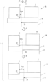
- Fig. 7 is a schematic cross section showing a further example of the clearance adjustment according to an exemplary embodiment of the invention.
- shearing equipment 7 in this example includes a transfer device 8 and shearing machines 1A to 1C, which are arranged along the transfer device 8 and configured to share the shearing process of the workpiece 6. It should be noted that each of the shearing machines 1A, 1B, and 1C does not have the clearance adjuster in this exemplary embodiment.
- the transfer device 8 which includes a robot arm, a belt conveyor and the like, is configured to transfer the workpiece 6 from an upstream to a downstream (i.e. from the shearing machine 1A to the shearing machine 1C in this order).
- H i.e. the movement distance of the upper blade 31 and/or the lower blade 21 in the thickness direction of the workpiece 6)
- the plurality of shearing machines 1A, 1B, 1C in this example are arranged in an ascending order of the clearances from the upstream to the downstream of the transfer path.
- the shearing equipment in the above example includes the three shearing machines 1A, 1B, 1C
- the shearing equipment may alternatively include two shearing machines or four or more shearing machines.
- the step for starting applying the shear force on the workpiece 6 with a clearance between the action points in the surface direction orthogonal to the thickness direction of the workpiece 6, the step for applying the shear force after the start of applying the shear force until the fractured surface 61 is created in the workpiece 6, and the step for increasing the clearance depending on a deformation of the workpiece 6 in the thickness direction until the fractured surface 61 is created in the workpiece 6 can be performed. Accordingly, the same effect(s) and advantage(s) as described above can be obtained.
- the clearance adjuster may be multiple dies 2 exchangeable during the shearing process.
- the multiple dies 2, which correspond to different clearances C are sequentially exchanged depending on the movement distance H of the upper blade 31 to change the clearance C in a stepwise manner.
- two types of the dies 2 each corresponding to an initial value of the clearance C (the clearance c 0 shown in Fig. 2A ) and an end value (the clearance c 2 shown in Fig. 2C ) may be prepared, which may be exchanged at one timing determined depending on the movement distance H of the upper blade 31 to increase the clearance C.
- the shearing machine according to the exemplary embodiment may be provided with the above-described clearance adjuster (e.g. the actuator 5a, the linear cam mechanism 5b) only at a part of a shearing portion and the other part of the shearing portion may be provided with no clearance adjuster (and, consequently, with fixed clearance). More specifically, the clearance adjuster may be provided, for instance, only at a curved portion at which the stretch-flange cracks are likely.
- the clearance adjuster e.g. the actuator 5a, the linear cam mechanism 5b
- the workpiece was a steel sheet with a tensile strength of 615 MPa and a plate thickness of 1 mm in all of Examples described below.
- the shearing process was punching using a 10-mm-diameter punch. Twelve dies with varying hole inner diameter from 10.1 mm to 10.4 mm in 0.025 mm increments were prepared and sequentially exchanged for shearing in accordance with the procedures explained below with reference to Figs. 8 and 9 .
- Fig. 8 is a graph for explaining Examples of the invention in which the clearance is continuously increased.
- the graph in Fig. 8 shows a relationship between the clearance C and the movement distance H of the upper blade in Examples 1 to 7.
- the clearance C is described with reference to a ratio to the plate thickness t (C/t) in the description of Examples below.
- the increase in the clearance C from 0.05 mm to 0.2 mm in 0.0125 mm increments by exchanging the dies results in the increase in C/t from 5% to 20% in 1.25% increments.
- the movement distance H is described with reference to a ratio to a reference movement distance H _re f (H/H _ref ) in the description of Examples below.
- the reference movement distance H _ref which is measured in a test conducted in advance, is used as an index common to Examples for controlling the clearance C.
- the twelve dies were sequentially exchanged while the H/H _ref varied from 0 to a predetermined value (10% in Example 1, 20% in Example 2, 40% in Example 3, 60% in Example 4, 80% in Example 5, 90% in Example 6, 100% in Example 7), thereby quasi-continuously increasing the C/t from 5% to 20%.
- H/H _ref reached the predetermined value, the movement of the upper blade was continued with C/t being kept at 20% until the fractured surface was created on the workpiece.
- Fig. 9 is a graph for explaining Examples of the invention in which the clearance is increased in a stepwise manner.
- the graph in Fig. 9 shows a relationship between the clearance C (C/t) and the movement distance H (H/H _ref ) of the upper blade in each of Examples 4 and 4s.
- the graph of Example 4 is the same as that shown in Fig. 8 .
- the dies were sequentially exchanged in the substantially same range of the movement distance H as in Example 4 to increase C/t from 5% to 20%.
- Example 4s used only four of the twelve dies to change the clearance C in 0.0375 mm increments (i.e. in 3.75% increments of C/t) in a stepwise manner.
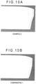
- Figs. 10A and 10B are photographs showing end profiles of the workpiece after being cut in Example and Comparative of the invention, respectively.
- Fig. 10A shows the end profile of the workpiece after being cut in Example 6 shown in Fig. 8 above.
- Comparative 1 Comparative
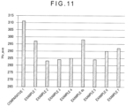
- Fig. 11 is a graph showing an average Vicker's hardness of an end face of the workpiece after being cut in Examples and Comparative of the invention.
- the hardness in each of Examples and Comparative was measured by: cutting the cut workpiece in a direction intersecting the end face; and conducting Vicker's hardness test (JIS Z 2244) at 14 points arranged in the thickness direction of the workpiece and remote from the end face by 80 microns. It should be noted that the points near the end face of the workpiece observed in Figs. 10A and 10B are the measured points in the Vicker's hardness test.
- the graph in Fig. 11 shows an average (Hv _ave ) of values at all the measured points of the measurements in the Vicker's hardness test in each of Examples and Comparative.
- Fig. 12 is a graph showing hole expandability of the workpiece after being cut in Examples and Comparative of the invention.
- the hole expandability was measured in a hole-expansion test (JIS Z 2256) conducted on the workpiece punched using a 10-mm-diameter punch as described above.
- the graph in Fig. 12 shows the hole expandability ( ⁇ ) measured in the hole-expansion test in each of Examples and Comparative.
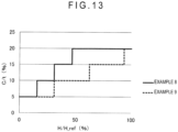
- Fig. 13 is a graph for explaining other Examples of the invention in which the clearance is increased in a stepwise manner.
- the graph in Fig. 13 shows a relationship between the clearance C (C/t) and the movement distance H (H/H ref ) of the upper blade in Examples 8 and 9.
- the clearance C was increased in a stepwise manner in Example 8, where the dies were exchanged so that C/t increased from the initial value of 5% in increments of 3.75% when H/H ref was 16%, 32%, and 48%. Thus, C/t increases in four stages from the initial value of 5% to the maximum value of 20%.
- the clearance C was increased in a stepwise manner in Example 9 as in Example 8, where the dies were exchanged when H/H ref was 32%, 64%, and 96%, thereby more gently increasing C/t.
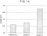
- Fig. 14 is a graph showing an opening ratio measured in a side bend test in Examples and Comparative shown in Fig. 13 .
- the side bend test is described in detail in " Evaluation and Improving Method of Stretch Flange-ability," Yoshida et al, Shinnittetsu giho, NIPPON STEEL CORPORATION, 2012, No. 393, p.18-24 .
- the step of increasing the clearance C is not necessarily performed in the range of the movement distance H equal to or less than 80% of H _ref , but the step of increasing the clearance C sometimes should be performed in the range the movement distance H exceeding 80% of H _ref .
- Fig. 15 is a graph for explaining Examples of the invention in which the clearance is increased at a single timing determined depending on the relative movement distance.
- the graph in Fig. 15 shows a relationship between the clearance C (C/t) and the movement distance H (H/H _ref ) of the upper blade in Comparative 2 and Examples 10, 11, and 12.
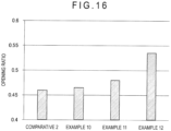
- Fig. 16 is a graph showing an opening ratio measured in a side bend test in Examples 10 to 12 and Comparative 2 shown in Fig. 15 .
- Fig. 16 shows an opening ratio measured in a side bend test in Examples 10 to 12 and Comparative 2 shown in Fig. 15 .
- the opening ratio which is as low as 46% in Comparative 2 gradually increases as H/H _ref (marking the die exchange timing) is increased, and significantly improves in Example 12.
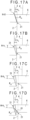
- a work-hardened region R 3A is developed between the upper blade 31 and the lower blade 21.
- a work-hardened region R 3B in the workpiece 6 enlarges as shown in Fig. 17B .
- the worked workpiece 6 since the work-hardened region is hardly present at the end of the workpiece 6, the worked workpiece 6 has a region without being influenced by the work-hardening on the fractured surface, thereby enlarging the opening ratio.
- the opening ratio is increased as the die exchanging timing H/H _ref is as close as the timing immediately before the fractured surface 61 is created. Accordingly, it is speculated that the clearance C should most preferably be increased at a timing immediately before the fractured surface 61 is created.
- the step for increasing the clearance C is started when the movement distance H is 0 (i.e. immediately after the upper blade is brought into contact with the upper side of the workpiece) in the above-described Examples, the step may be started when the movement distance H reaches a predetermined value that is larger than 0 (i.e. when the upper blade is pushed against the workpiece to some degree).
- the inventors have found that the invention is more effectively appliable on a steel sheet with a relatively high strength (i.e. having a tensile strength of 270 MPa or more). This is because the behavior of the workpiece described in the above exemplary embodiment of the invention, which is on the premise that ductile fracture cracks occur during the shearing process, is not likely to occur in a steel sheet with low strength because of its excellent local deformability.
- the inventors have found that the invention is effectively applicable to a high-strength steel sheet with, for instance, a tensile strength of 980 MPa or more, in which the ductile fracture cracks stably occur during the shearing process.
- the inventors have found that the invention is more effectively applied on a workpiece in a form of a steel sheet with a thickness ranging from 0.2 mm to 2 mm. This is because, when the plate thickness is excessively small, the clearance C becomes small in accordance therewith, so that it becomes difficult to stably control the clearance C by the clearance adjuster. Meanwhile, when the plate thickness is excessively large, the end profile often changes in accordance with the change in the clearance C, so that the effect for reducing the influence of work-hardening at the end surface of the workpiece is not easily obtained.
- the invention is effectively applicable to a workpiece whose plate thickness ranges from 0.1 mm to 4 mm, or from 0.05 mm to 8 mm depending on the material of the workpiece and the shape of the sheared portion.
- the workpiece of the invention is not necessarily a steel sheet but may be other metal plate (e.g. aluminum alloy plate).
Landscapes
- Engineering & Computer Science (AREA)
- Mechanical Engineering (AREA)
- Life Sciences & Earth Sciences (AREA)
- Forests & Forestry (AREA)
- Shearing Machines (AREA)
- Punching Or Piercing (AREA)
Claims (19)
- Scherverfahren zum Ausüben einer Scherkraft auf ein plattenförmiges Werkstück (6) in einer einzigen Richtung in einer Dickenrichtung, um das Werkstück (6) zu schneiden, wobei das Verfahren aufweist:Beginnen der Ausübung der Scherkraft auf das Werkstück (6) mit einem Spalt (C) zwischen Angriffspunkten in einer Oberflächenrichtung orthogonal zur Dickenrichtung des Werkstücks (6);Ausüben der Scherkraft nach Beginn des Ausübens der Scherkraft, bis eine Bruchfläche (61) auf dem Werkstück (6) erzeugt wird, undVergrößern des Spalts (C) in Abhängigkeit vom Relativbewegungsabstand der Angriffspunkte in der Dickenrichtung des Werkstücks (6) nach Beginn des Ausübens der Scherkraft, bis die Bruchfläche (61) auf dem Werkstück (6) erzeugt ist,wobei C/t, ein Verhältnis des Spalts (C) zu einer Dicke (t) des Werkstücks (6) mindestens 5 % und höchstens 20 % beträgt.
- Scherverfahren nach Anspruch 1, wobeidas Verfahren mit Hilfe mehrerer Schermaschinen (1) durchgeführt wird, die jeweils aufweisen: ein Untermesser (21) und ein Obermesser (31), das in der Dickenrichtung des Werkstücks (6) relativ zum Untermesser (21) beweglich ist, wobei sich ein Spalt, der zwischen dem Untermesser (21) und dem Obermesser (31) entlang der Oberflächenrichtung des Werkstücks (6) gebildet ist, in jeder der mehreren Schermaschinen unterscheidet, undbeim Vergrößern des Spalts die Scherkraft von einer der mehreren Schermaschinen, deren Spalt klein ist, zu einer der mehreren Schermaschinen, deren Spalt groß ist, nacheinander auf das Werkstück (6) ausgeübt wird.
- Scherverfahren nach Anspruch 1, wobei
das Verfahren mit Hilfe einer einzelnen Schermaschine durchgeführt wird, die aufweist: ein Untermesser (21), das so konfiguriert ist, dass es in Kontakt mit einer Unterseite des Werkstücks (6) steht, und ein Obermesser (31), das in der Dickenrichtung des Werkstücks (6) relativ zum Untermesser (21) beweglich ist, und das Verfahren ferner aufweist:In-Kontakt-bringen des Untermessers (21) mit der Unterseite des Werkstücks (6);Bewegen des Obermessers (31) in der Dickenrichtung, bis das Obermesser (31) in Kontakt mit einer Oberseite des Werkstücks (6) steht, während der Spalt im Hinblick auf das Untermesser (21) in der Oberflächenrichtung des Werkstücks (6) beibehalten wird,weiteres Bewegen des Obermessers (31) in Kontakt mit der Oberseite des Werkstücks (6) in der Dickenrichtung des Werkstücks (6), bis eine Bruchfläche (61) im Werkstück (6) erzeugt wird, undVergrößern des Spalts in Abhängigkeit von einem Relativbewegungsabstand des Obermessers (31) und des Untermessers (21) in der Dickenrichtung des Werkstücks (6), nachdem das Obermesser (31) in Kontakt mit der Oberseite des Werkstücks (6) steht, bis die Bruchfläche (61) erzeugt wird. - Scherverfahren nach Anspruch 3, wobeidas Untermesser relativ zum Obermesser (31) in der Oberflächenrichtung des Werkstücks (6) beweglich ist undbeim Vergrößern des Spalts das Untermesser (21) und das Obermesser in Abhängigkeit vom Relativbewegungsabstand zwischen dem Obermesser (31) und dem Untermesser (21) in der Dickenrichtung des Werkstücks (6) relativ voneinander weg bewegt werden.
- Scherverfahren nach Anspruch 3 oder 4, wobei
beim Vergrößern des Spalts der Spalt in Abhängigkeit vom Relativbewegungsabstand zwischen dem Obermesser (31) und dem Untermesser (21) in der Dickenrichtung des Werkstücks (6) kontinuierlich vergrößert wird. - Scherverfahren nach Anspruch 3 oder 4, wobei
beim Vergrößern des Spalts der Spalt in Abhängigkeit vom Relativbewegungsabstand zwischen dem Obermesser (31) und dem Untermesser (21) in der Dickenrichtung des Werkstücks (6) schrittweise vergrößert wird. - Scherverfahren nach Anspruch 3 oder 4, wobei
beim Vergrößern des Spalts der Spalt zu einer einzigen Zeit vergrößert wird, die in Abhängigkeit vom Relativbewegungsabstand zwischen dem Obermesser (31) und dem Untermesser (21) in der Dickenrichtung des Werkstücks (6) bestimmt wird. - Scherverfahren nach einem der Ansprüche 3 bis 7, wobei
die Vergrößerung des Spalts geschieht, wenn der Relativbewegungsabstand des Obermessers (31) und des Untermessers (21) mindestens 20 % eines Referenzbewegungsabstands beträgt, der dem Relativbewegungsabstand des Obermessers (31) und des Untermessers (21) in der Dickenrichtung des Werkstücks (6) entspricht, nachdem das Obermesser (31) in Kontakt mit der Oberseite des Werkstücks (6) steht, bis die Bruchfläche (61) erzeugt wird, wenn der Spalt auf einen vorbestimmten Wert fixiert ist. - Scherverfahren nach einem der Ansprüche 1 bis 8, wobei das Werkstück (6) ein Stahlblech mit einer Zugfestigkeit von mindestens 270 MPa ist.
- Scherverfahren nach einem der Ansprüche 1 bis 9, wobei das Werkstück (6) ein Stahlblech mit einer Dicke im Bereich von 0,2 mm bis 2 mm ist.
- Schermaschine, die so konfiguriert ist, dass sie eine Scherkraft auf ein plattenförmiges Werkstück (6) in einer einzigen Richtung in einer Dickenrichtung ausübt, um das Werkstück (6) zu schneiden, und die aufweist:ein Untermesser (21);ein Obermesser (31), das in einer Annäherungs-/Trennrichtung relativ zum Untermesser (21) beweglich ist, wobei das Obermesser (31) zum Untermesser (21) mit einem Spalt (C) in einer Richtung orthogonal zur Annäherungs-/Trennrichtung weist, wobei die Maschine dadurch gekennzeichnet ist, dass sie ferner aufweist:einen Spalteinsteller (5a), der so konfiguriert ist, dass er den Spalt (C) in Abhängigkeit von einem Bewegungsabstand des Obermessers (31) in der Annäherungsrichtung nach Beginn des Ausübens der Scherkraft vergrößert, bis eine Bruchfläche auf dem Werkstück erzeugt wird,wobei C/t, ein Verhältnis des Spalts (C) zu einer Dicke (t) des Werkstücks (6) mindestens 5 % und höchstens 20 % beträgt.
- Schermaschine nach Anspruch 11, wobeidas Untermesser (21) in der Richtung orthogonal zur Annäherungs-/Trennrichtung relativ zum Obermesser (31) beweglich ist undder Spalteinsteller (5a) so konfiguriert ist, dass er das Untermesser (21) in Abhängigkeit vom Relativbewegungsabstand des Obermessers (31) und des Untermessers (21) in der Annäherungsrichtung weg vom Obermesser (31) bewegt.
- Schermaschine nach Anspruch 11 oder 12, wobei der Spalteinsteller (5a) so konfiguriert ist, dass er den Spalt (C) in Abhängigkeit vom Relativbewegungsabstand des Obermessers (31) und des Untermessers (21) in der Annäherungsrichtung kontinuierlich vergrößert.
- Schermaschine nach Anspruch 13, wobei der Spalteinsteller aufweist:eine erste Schrägfläche (51), die in einer Relativbewegungsrichtung des Obermessers (31) und des Untermessers (21) in einem Stück mit dem Obermesser (31) beweglich ist, undeine zweite Schrägfläche (52), die so konfiguriert ist, dass sie in gleitfähigem Kontakt mit der ersten Schrägfläche (51) steht und in einer Richtung orthogonal zur Relativbewegungsrichtung des Obermessers (31) und des Untermessers (21) in einem Stück mit dem Untermesser (21) beweglich ist, unddie Schermaschine ferner einen Spalthalter (22) aufweist, der so konfiguriert ist, dass sie den Spalt (C) beibehält, wenn die erste Schrägfläche (51) nicht in gleitfähigem Kontakt mit der zweiten Schrägfläche (52) steht.
- Schermaschine nach Anspruch 13, wobei der Spalteinsteller (5a) ein elastisches Teil aufweist, das so konfiguriert ist, dass es eine elastische Kraft auf das Untermesser (21) ausübt, wobei die elastische Kraft einer Schubkraft entgegenwirkt, die durch das Untermesser (21) in der Richtung orthogonal zur Annäherungsrichtung des Obermessers (31) als Reaktion auf eine Bewegung des Obermessers (31) in der Annäherungsrichtung aufgenommen wird.
- Schermaschine nach Anspruch 11 oder 12, wobei der Spalteinsteller (5a) so konfiguriert ist, dass er den Spalt (C) in Abhängigkeit vom Relativbewegungsabstand des Obermessers (31) und des Untermessers (21) in der Annäherungsrichtung schrittweise vergrößert.
- Schermaschine nach Anspruch 11 oder 12, wobei der Spalteinsteller (5a) so konfiguriert ist, dass er den Spalt (C) zu einer einzigen Zeit vergrößert, die in Abhängigkeit vom Relativbewegungsabstand des Obermessers (31) und des Untermessers (21) in der Annäherungsrichtung bestimmt ist.
- Schermaschine nach einem der Ansprüche 11 bis 17, wobei der Spalteinsteller (5a) so konfiguriert ist, dass er den Spalt (C) vergrößert, wenn der Relativbewegungsabstand des Obermessers (31) und des Untermessers (21) mindestens 20 % eines Referenzbewegungsabstands erreicht, der dem Relativbewegungsabstand des Obermessers (31) und des Untermessers (21) von einem Beginn bis zu einem Ende des Scherens entspricht.
- Scheranlage, die so konfiguriert ist, dass sie eine Scherkraft auf ein plattenförmiges Werkstück (6) in einer einzigen Richtung in einer Dickenrichtung ausübt, um das Werkstück (6) zu schneiden, und die aufweist:eine Transportvorrichtung, die so konfiguriert ist, dass sie ein Werkstück (6) transportiert; undmehrere Schermaschinen (1A, 1B, 1C), die entlang eines Transportwegs der Transportvorrichtung angeordnet sind, wobei die mehreren Schermaschinen (1A, 1B, 1C) so konfiguriert sind, dass sie sich einen Schervorgang am Werkstück (6) aufteilen, wobeijede der mehreren Schermaschinen (1A, 1B, 1C) aufweist: ein Untermesser (21); und ein Obermesser (31), das in einer Annäherungs-/Trennrichtung relativ zum Untermesser (21) beweglich ist, wobei das Obermesser (31) zum Untermesser (21) mit einem Spalt (C) in einer Richtung orthogonal zur Annäherungs-/Trennrichtung weist, undwobei die mehreren Schermaschinen (1A, 1B, 1C) in einer aufsteigenden Reihenfolge des Spalts (C) in jeder der mehreren Schermaschinen von einer vorgelagerten zu einer nachgelagerten Seite des Transportwegs angeordnet sind,wobei die Anlage dadurch gekennzeichnet ist, dass jede der mehreren Schermaschinen so konfiguriert ist, dassC/t, ein Verhältnis des Spalts (C) zu einer Dicke (t) des Werkstücks (6) mindestens 5 % und höchstens 20 % beträgt.
Applications Claiming Priority (2)
| Application Number | Priority Date | Filing Date | Title |
|---|---|---|---|
| JP2017060982 | 2017-03-27 | ||
| PCT/JP2018/011209 WO2018180820A1 (ja) | 2017-03-27 | 2018-03-20 | せん断加工方法、せん断加工装置、およびせん断加工設備 |
Publications (3)
| Publication Number | Publication Date |
|---|---|
| EP3603839A1 EP3603839A1 (de) | 2020-02-05 |
| EP3603839A4 EP3603839A4 (de) | 2020-12-09 |
| EP3603839B1 true EP3603839B1 (de) | 2025-01-08 |
Family
ID=63675580
Family Applications (1)
| Application Number | Title | Priority Date | Filing Date |
|---|---|---|---|
| EP18775469.2A Active EP3603839B1 (de) | 2017-03-27 | 2018-03-20 | Scherverfahren, schervorrichtung und scheranlage |
Country Status (9)
| Country | Link |
|---|---|
| US (2) | US11819899B2 (de) |
| EP (1) | EP3603839B1 (de) |
| JP (2) | JP6927288B2 (de) |
| KR (1) | KR102255626B1 (de) |
| CN (1) | CN110382131A (de) |
| BR (1) | BR112019018409A2 (de) |
| CA (1) | CA3055165A1 (de) |
| MX (2) | MX2019010510A (de) |
| WO (1) | WO2018180820A1 (de) |
Families Citing this family (2)
| Publication number | Priority date | Publication date | Assignee | Title |
|---|---|---|---|---|
| EP3603839B1 (de) * | 2017-03-27 | 2025-01-08 | Nippon Steel Corporation | Scherverfahren, schervorrichtung und scheranlage |
| JP7695536B2 (ja) * | 2020-08-07 | 2025-06-19 | 日本製鉄株式会社 | せん断加工装置及びせん断加工方法 |
Citations (2)
| Publication number | Priority date | Publication date | Assignee | Title |
|---|---|---|---|---|
| WO2006080356A1 (ja) * | 2005-01-25 | 2006-08-03 | Aisin Aw Co., Ltd. | プレス加工装置、プレス加工方法、及び打抜き加工品 |
| JP2016087642A (ja) * | 2014-11-04 | 2016-05-23 | 新日鐵住金株式会社 | 金属薄板のせん断加工型、その設計方法、及び、その加工型を備えるせん断装置 |
Family Cites Families (23)
| Publication number | Priority date | Publication date | Assignee | Title |
|---|---|---|---|---|
| US3183756A (en) * | 1962-12-26 | 1965-05-18 | Cleveland Crane Eng | Clearance, rake angle, and stroke length adjusting means for power shears |
| DE4108041A1 (de) * | 1991-03-13 | 1992-09-17 | Bwg Bergwerk Walzwerk | Vorrichtung zum schneiden von blechen und insbesondere metallbaendern |
| JPH0751919A (ja) * | 1993-08-06 | 1995-02-28 | Nissan Motor Co Ltd | プレス装置 |
| JPH07265967A (ja) * | 1994-03-31 | 1995-10-17 | Amada Co Ltd | プレスによる追切り加工方法および装置並びに金型 |
| JPH09314250A (ja) * | 1996-03-28 | 1997-12-09 | Topy Ind Ltd | せん断穴あけ加工方法 |
| JPH10113726A (ja) * | 1996-10-09 | 1998-05-06 | Topy Ind Ltd | 同一方向二工程せん断穴あけ加工方法 |
| US5820999A (en) * | 1996-11-01 | 1998-10-13 | Aluminum Company Of America | Trimmed aluminum sheet |
| JPH1110437A (ja) * | 1997-06-27 | 1999-01-19 | Murata Mach Ltd | シャーリング機 |
| JP4444391B2 (ja) | 1999-05-06 | 2010-03-31 | 株式会社アマダ | 剪断加工装置 |
| JP4778257B2 (ja) * | 2005-04-11 | 2011-09-21 | 日本特殊陶業株式会社 | 配線基板の製造方法およびセラミックグリーンシートの打ち抜き装置 |
| EP1974843A3 (de) * | 2007-03-29 | 2012-03-21 | FUJIFILM Corporation | Flachdruckplatte sowie Vorrichtung und Verfahren zu dessen Herstellung |
| JP5058677B2 (ja) * | 2007-05-22 | 2012-10-24 | 中央精機株式会社 | 車両用ホイールのハブ孔フランジ部成形方法 |
| JP5493687B2 (ja) | 2009-10-20 | 2014-05-14 | 新日鐵住金株式会社 | せん断加工条件の設定方法 |
| JP5671668B2 (ja) | 2010-04-14 | 2015-02-18 | 本田技研工業株式会社 | クリアランス調整機構 |
| CN202239177U (zh) * | 2011-09-05 | 2012-05-30 | 南车长江车辆有限公司 | 可调冲裁间隙切断模具 |
| GB2509949B (en) * | 2013-01-18 | 2015-12-02 | Primetals Technologies Ltd | A method and apparatus for operating a shear |
| JP2016087842A (ja) | 2014-10-31 | 2016-05-23 | キヤノンマーケティングジャパン株式会社 | 印刷装置、制御方法、及びプログラム |
| US10465260B2 (en) * | 2015-04-10 | 2019-11-05 | The Nanosteel Company, Inc. | Edge formability in metallic alloys |
| CN205200281U (zh) * | 2015-11-27 | 2016-05-04 | 深圳职业技术学院 | 冲切用的凹模及其冲切模具 |
| CN105750403A (zh) * | 2016-04-18 | 2016-07-13 | 旌德县皖星电子电器厂 | 一种固定片侧面冲孔模 |
| EP3603839B1 (de) * | 2017-03-27 | 2025-01-08 | Nippon Steel Corporation | Scherverfahren, schervorrichtung und scheranlage |
| GB2571782B (en) * | 2018-03-09 | 2020-08-05 | Magna Int Inc | Die cutting insert and method for cutting sheet metals |
| JP3217507U (ja) * | 2018-06-01 | 2018-08-09 | 住友電工プリントサーキット株式会社 | 打抜装置 |
-
2018
- 2018-03-20 EP EP18775469.2A patent/EP3603839B1/de active Active
- 2018-03-20 CA CA3055165A patent/CA3055165A1/en not_active Abandoned
- 2018-03-20 BR BR112019018409A patent/BR112019018409A2/pt not_active Application Discontinuation
- 2018-03-20 MX MX2019010510A patent/MX2019010510A/es unknown
- 2018-03-20 US US16/498,364 patent/US11819899B2/en active Active
- 2018-03-20 CN CN201880015613.9A patent/CN110382131A/zh active Pending
- 2018-03-20 WO PCT/JP2018/011209 patent/WO2018180820A1/ja not_active Ceased
- 2018-03-20 JP JP2019509626A patent/JP6927288B2/ja active Active
- 2018-03-20 KR KR1020197026012A patent/KR102255626B1/ko active Active
-
2019
- 2019-09-04 MX MX2024004627A patent/MX2024004627A/es unknown
-
2021
- 2021-06-03 JP JP2021093743A patent/JP7074240B2/ja active Active
-
2023
- 2023-10-10 US US18/484,254 patent/US12350728B2/en active Active
Patent Citations (2)
| Publication number | Priority date | Publication date | Assignee | Title |
|---|---|---|---|---|
| WO2006080356A1 (ja) * | 2005-01-25 | 2006-08-03 | Aisin Aw Co., Ltd. | プレス加工装置、プレス加工方法、及び打抜き加工品 |
| JP2016087642A (ja) * | 2014-11-04 | 2016-05-23 | 新日鐵住金株式会社 | 金属薄板のせん断加工型、その設計方法、及び、その加工型を備えるせん断装置 |
Also Published As
| Publication number | Publication date |
|---|---|
| US11819899B2 (en) | 2023-11-21 |
| US20200030868A1 (en) | 2020-01-30 |
| WO2018180820A1 (ja) | 2018-10-04 |
| US20240033804A1 (en) | 2024-02-01 |
| MX2019010510A (es) | 2019-10-14 |
| KR20190116362A (ko) | 2019-10-14 |
| CN110382131A (zh) | 2019-10-25 |
| BR112019018409A2 (pt) | 2020-04-07 |
| JPWO2018180820A1 (ja) | 2019-12-12 |
| JP2021142569A (ja) | 2021-09-24 |
| EP3603839A4 (de) | 2020-12-09 |
| US12350728B2 (en) | 2025-07-08 |
| MX2024004627A (es) | 2024-04-30 |
| KR102255626B1 (ko) | 2021-05-25 |
| JP6927288B2 (ja) | 2021-08-25 |
| JP7074240B2 (ja) | 2022-05-24 |
| EP3603839A1 (de) | 2020-02-05 |
| CA3055165A1 (en) | 2018-10-04 |
Similar Documents
| Publication | Publication Date | Title |
|---|---|---|
| US12350728B2 (en) | Shearing method, shearing device, and shearing facility | |
| EP3266531B1 (de) | Presssysteme und -verfahren | |
| EP3231527B1 (de) | Rohling, matrizenanordnung und verfahren zur herstellung eines rohlings | |
| EP3060687B1 (de) | Verfahren zum bearbeiten eines heissgeschmiedeten teils | |
| WO2007084089A2 (en) | Method for delaying of cooling and hardening of desired zones of a sheet during a hot metal stamping process | |
| EP2305395B1 (de) | Pressarbeitseinrichtung und pressarbeitsverfahren | |
| US8727196B2 (en) | Feeder apparatus for metal strip | |
| US20190291160A1 (en) | Method for machining a sheet-metal profile | |
| CN111819053B (zh) | 模切刀具和用于切割金属板的方法 | |
| US6923103B2 (en) | Machine for the continuous multi-stroke slotting of plate-shaped workpieces | |
| US9266160B2 (en) | Method for forming an undercut and method for manufacturing a formed article having an undercut | |
| EP1733818B1 (de) | Schervorrichtung | |
| JP2006224121A (ja) | 鋼板打ち抜き用工具及びそれを用いた打ち抜き方法 | |
| JPH11290951A (ja) | 高強度鋼板のプレス成形方法およびプレス成形装置 | |
| WO2020145063A1 (ja) | 金属板のせん断加工方法及びプレス部品の製造方法 | |
| JP2017039158A (ja) | 連続穴抜き方法および連続穴抜き装置 | |
| US20220143665A1 (en) | Tool and method for processing plate-shaped workpieces | |
| JP2006231425A (ja) | 切断面割れを低減するシャーせん断刃、せん断加工方法およびせん断加工装置 | |
| EP2465622B1 (de) | Gesenk zum Beschneiden einer geschmiedeten Komponente |
Legal Events
| Date | Code | Title | Description |
|---|---|---|---|
| STAA | Information on the status of an ep patent application or granted ep patent |
Free format text: STATUS: THE INTERNATIONAL PUBLICATION HAS BEEN MADE |
|
| PUAI | Public reference made under article 153(3) epc to a published international application that has entered the european phase |
Free format text: ORIGINAL CODE: 0009012 |
|
| STAA | Information on the status of an ep patent application or granted ep patent |
Free format text: STATUS: REQUEST FOR EXAMINATION WAS MADE |
|
| 17P | Request for examination filed |
Effective date: 20191006 |
|
| AK | Designated contracting states |
Kind code of ref document: A1 Designated state(s): AL AT BE BG CH CY CZ DE DK EE ES FI FR GB GR HR HU IE IS IT LI LT LU LV MC MK MT NL NO PL PT RO RS SE SI SK SM TR |
|
| AX | Request for extension of the european patent |
Extension state: BA ME |
|
| DAV | Request for validation of the european patent (deleted) | ||
| DAX | Request for extension of the european patent (deleted) | ||
| A4 | Supplementary search report drawn up and despatched |
Effective date: 20201111 |
|
| RIC1 | Information provided on ipc code assigned before grant |
Ipc: B21D 28/02 20060101AFI20201105BHEP Ipc: B21D 37/08 20060101ALI20201105BHEP |
|
| REG | Reference to a national code |
Ref country code: DE Ref legal event code: R079 Free format text: PREVIOUS MAIN CLASS: B21D0028340000 Ipc: B21D0028020000 Ref document number: 602018078363 Country of ref document: DE |
|
| GRAP | Despatch of communication of intention to grant a patent |
Free format text: ORIGINAL CODE: EPIDOSNIGR1 |
|
| STAA | Information on the status of an ep patent application or granted ep patent |
Free format text: STATUS: GRANT OF PATENT IS INTENDED |
|
| RIC1 | Information provided on ipc code assigned before grant |
Ipc: B21D 37/08 20060101ALI20240315BHEP Ipc: B21D 28/02 20060101AFI20240315BHEP |
|
| INTG | Intention to grant announced |
Effective date: 20240418 |
|
| GRAJ | Information related to disapproval of communication of intention to grant by the applicant or resumption of examination proceedings by the epo deleted |
Free format text: ORIGINAL CODE: EPIDOSDIGR1 |
|
| STAA | Information on the status of an ep patent application or granted ep patent |
Free format text: STATUS: REQUEST FOR EXAMINATION WAS MADE |
|
| INTC | Intention to grant announced (deleted) | ||
| GRAP | Despatch of communication of intention to grant a patent |
Free format text: ORIGINAL CODE: EPIDOSNIGR1 |
|
| STAA | Information on the status of an ep patent application or granted ep patent |
Free format text: STATUS: GRANT OF PATENT IS INTENDED |
|
| INTG | Intention to grant announced |
Effective date: 20240826 |
|
| GRAS | Grant fee paid |
Free format text: ORIGINAL CODE: EPIDOSNIGR3 |
|
| GRAA | (expected) grant |
Free format text: ORIGINAL CODE: 0009210 |
|
| STAA | Information on the status of an ep patent application or granted ep patent |
Free format text: STATUS: THE PATENT HAS BEEN GRANTED |
|
| AK | Designated contracting states |
Kind code of ref document: B1 Designated state(s): AL AT BE BG CH CY CZ DE DK EE ES FI FR GB GR HR HU IE IS IT LI LT LU LV MC MK MT NL NO PL PT RO RS SE SI SK SM TR |
|
| REG | Reference to a national code |
Ref country code: GB Ref legal event code: FG4D |
|
| REG | Reference to a national code |
Ref country code: CH Ref legal event code: EP |
|
| REG | Reference to a national code |
Ref country code: DE Ref legal event code: R096 Ref document number: 602018078363 Country of ref document: DE |
|
| REG | Reference to a national code |
Ref country code: IE Ref legal event code: FG4D |
|
| REG | Reference to a national code |
Ref country code: LT Ref legal event code: MG9D |
|
| REG | Reference to a national code |
Ref country code: NL Ref legal event code: MP Effective date: 20250108 |
|
| REG | Reference to a national code |
Ref country code: AT Ref legal event code: MK05 Ref document number: 1758003 Country of ref document: AT Kind code of ref document: T Effective date: 20250108 |
|
| PG25 | Lapsed in a contracting state [announced via postgrant information from national office to epo] |
Ref country code: NL Free format text: LAPSE BECAUSE OF FAILURE TO SUBMIT A TRANSLATION OF THE DESCRIPTION OR TO PAY THE FEE WITHIN THE PRESCRIBED TIME-LIMIT Effective date: 20250108 |
|
| PG25 | Lapsed in a contracting state [announced via postgrant information from national office to epo] |
Ref country code: RS Free format text: LAPSE BECAUSE OF FAILURE TO SUBMIT A TRANSLATION OF THE DESCRIPTION OR TO PAY THE FEE WITHIN THE PRESCRIBED TIME-LIMIT Effective date: 20250408 |
|
| PG25 | Lapsed in a contracting state [announced via postgrant information from national office to epo] |
Ref country code: FI Free format text: LAPSE BECAUSE OF FAILURE TO SUBMIT A TRANSLATION OF THE DESCRIPTION OR TO PAY THE FEE WITHIN THE PRESCRIBED TIME-LIMIT Effective date: 20250108 |
|
| PG25 | Lapsed in a contracting state [announced via postgrant information from national office to epo] |
Ref country code: PL Free format text: LAPSE BECAUSE OF FAILURE TO SUBMIT A TRANSLATION OF THE DESCRIPTION OR TO PAY THE FEE WITHIN THE PRESCRIBED TIME-LIMIT Effective date: 20250108 |
|
| PG25 | Lapsed in a contracting state [announced via postgrant information from national office to epo] |
Ref country code: ES Free format text: LAPSE BECAUSE OF FAILURE TO SUBMIT A TRANSLATION OF THE DESCRIPTION OR TO PAY THE FEE WITHIN THE PRESCRIBED TIME-LIMIT Effective date: 20250108 |
|
| PG25 | Lapsed in a contracting state [announced via postgrant information from national office to epo] |
Ref country code: NO Free format text: LAPSE BECAUSE OF FAILURE TO SUBMIT A TRANSLATION OF THE DESCRIPTION OR TO PAY THE FEE WITHIN THE PRESCRIBED TIME-LIMIT Effective date: 20250408 Ref country code: IS Free format text: LAPSE BECAUSE OF FAILURE TO SUBMIT A TRANSLATION OF THE DESCRIPTION OR TO PAY THE FEE WITHIN THE PRESCRIBED TIME-LIMIT Effective date: 20250508 |
|
| PG25 | Lapsed in a contracting state [announced via postgrant information from national office to epo] |
Ref country code: HR Free format text: LAPSE BECAUSE OF FAILURE TO SUBMIT A TRANSLATION OF THE DESCRIPTION OR TO PAY THE FEE WITHIN THE PRESCRIBED TIME-LIMIT Effective date: 20250108 |
|
| PG25 | Lapsed in a contracting state [announced via postgrant information from national office to epo] |
Ref country code: LV Free format text: LAPSE BECAUSE OF FAILURE TO SUBMIT A TRANSLATION OF THE DESCRIPTION OR TO PAY THE FEE WITHIN THE PRESCRIBED TIME-LIMIT Effective date: 20250108 Ref country code: PT Free format text: LAPSE BECAUSE OF FAILURE TO SUBMIT A TRANSLATION OF THE DESCRIPTION OR TO PAY THE FEE WITHIN THE PRESCRIBED TIME-LIMIT Effective date: 20250508 |
|
| PG25 | Lapsed in a contracting state [announced via postgrant information from national office to epo] |
Ref country code: GR Free format text: LAPSE BECAUSE OF FAILURE TO SUBMIT A TRANSLATION OF THE DESCRIPTION OR TO PAY THE FEE WITHIN THE PRESCRIBED TIME-LIMIT Effective date: 20250409 Ref country code: BG Free format text: LAPSE BECAUSE OF FAILURE TO SUBMIT A TRANSLATION OF THE DESCRIPTION OR TO PAY THE FEE WITHIN THE PRESCRIBED TIME-LIMIT Effective date: 20250108 |
|
| PG25 | Lapsed in a contracting state [announced via postgrant information from national office to epo] |
Ref country code: AT Free format text: LAPSE BECAUSE OF FAILURE TO SUBMIT A TRANSLATION OF THE DESCRIPTION OR TO PAY THE FEE WITHIN THE PRESCRIBED TIME-LIMIT Effective date: 20250108 |
|
| PG25 | Lapsed in a contracting state [announced via postgrant information from national office to epo] |
Ref country code: SE Free format text: LAPSE BECAUSE OF FAILURE TO SUBMIT A TRANSLATION OF THE DESCRIPTION OR TO PAY THE FEE WITHIN THE PRESCRIBED TIME-LIMIT Effective date: 20250108 |
|
| PG25 | Lapsed in a contracting state [announced via postgrant information from national office to epo] |
Ref country code: SM Free format text: LAPSE BECAUSE OF FAILURE TO SUBMIT A TRANSLATION OF THE DESCRIPTION OR TO PAY THE FEE WITHIN THE PRESCRIBED TIME-LIMIT Effective date: 20250108 |
|
| REG | Reference to a national code |
Ref country code: DE Ref legal event code: R097 Ref document number: 602018078363 Country of ref document: DE |
|
| PG25 | Lapsed in a contracting state [announced via postgrant information from national office to epo] |
Ref country code: DK Free format text: LAPSE BECAUSE OF FAILURE TO SUBMIT A TRANSLATION OF THE DESCRIPTION OR TO PAY THE FEE WITHIN THE PRESCRIBED TIME-LIMIT Effective date: 20250108 |
|
| PG25 | Lapsed in a contracting state [announced via postgrant information from national office to epo] |
Ref country code: MC Free format text: LAPSE BECAUSE OF FAILURE TO SUBMIT A TRANSLATION OF THE DESCRIPTION OR TO PAY THE FEE WITHIN THE PRESCRIBED TIME-LIMIT Effective date: 20250108 |
|
| PG25 | Lapsed in a contracting state [announced via postgrant information from national office to epo] |
Ref country code: CZ Free format text: LAPSE BECAUSE OF FAILURE TO SUBMIT A TRANSLATION OF THE DESCRIPTION OR TO PAY THE FEE WITHIN THE PRESCRIBED TIME-LIMIT Effective date: 20250108 Ref country code: EE Free format text: LAPSE BECAUSE OF FAILURE TO SUBMIT A TRANSLATION OF THE DESCRIPTION OR TO PAY THE FEE WITHIN THE PRESCRIBED TIME-LIMIT Effective date: 20250108 |
|
| REG | Reference to a national code |
Ref country code: CH Ref legal event code: H13 Free format text: ST27 STATUS EVENT CODE: U-0-0-H10-H13 (AS PROVIDED BY THE NATIONAL OFFICE) Effective date: 20251023 |
|
| PG25 | Lapsed in a contracting state [announced via postgrant information from national office to epo] |
Ref country code: RO Free format text: LAPSE BECAUSE OF FAILURE TO SUBMIT A TRANSLATION OF THE DESCRIPTION OR TO PAY THE FEE WITHIN THE PRESCRIBED TIME-LIMIT Effective date: 20250108 |
|
| PG25 | Lapsed in a contracting state [announced via postgrant information from national office to epo] |
Ref country code: SK Free format text: LAPSE BECAUSE OF FAILURE TO SUBMIT A TRANSLATION OF THE DESCRIPTION OR TO PAY THE FEE WITHIN THE PRESCRIBED TIME-LIMIT Effective date: 20250108 |
|
| PLBE | No opposition filed within time limit |
Free format text: ORIGINAL CODE: 0009261 |
|
| STAA | Information on the status of an ep patent application or granted ep patent |
Free format text: STATUS: NO OPPOSITION FILED WITHIN TIME LIMIT |
|
| PG25 | Lapsed in a contracting state [announced via postgrant information from national office to epo] |
Ref country code: LU Free format text: LAPSE BECAUSE OF NON-PAYMENT OF DUE FEES Effective date: 20250320 |
|
| REG | Reference to a national code |
Ref country code: BE Ref legal event code: MM Effective date: 20250331 |
|
| 26N | No opposition filed |
Effective date: 20251009 |
|
| GBPC | Gb: european patent ceased through non-payment of renewal fee |
Effective date: 20250408 |
|
| PG25 | Lapsed in a contracting state [announced via postgrant information from national office to epo] |
Ref country code: GB Free format text: LAPSE BECAUSE OF NON-PAYMENT OF DUE FEES Effective date: 20250408 |
|
| PG25 | Lapsed in a contracting state [announced via postgrant information from national office to epo] |
Ref country code: BE Free format text: LAPSE BECAUSE OF NON-PAYMENT OF DUE FEES Effective date: 20250331 |
|
| PG25 | Lapsed in a contracting state [announced via postgrant information from national office to epo] |
Ref country code: CH Free format text: LAPSE BECAUSE OF NON-PAYMENT OF DUE FEES Effective date: 20250331 |
|
| PG25 | Lapsed in a contracting state [announced via postgrant information from national office to epo] |
Ref country code: IE Free format text: LAPSE BECAUSE OF NON-PAYMENT OF DUE FEES Effective date: 20250320 |
|
| PG25 | Lapsed in a contracting state [announced via postgrant information from national office to epo] |
Ref country code: IT Free format text: LAPSE BECAUSE OF FAILURE TO SUBMIT A TRANSLATION OF THE DESCRIPTION OR TO PAY THE FEE WITHIN THE PRESCRIBED TIME-LIMIT Effective date: 20250108 |
|
| PGFP | Annual fee paid to national office [announced via postgrant information from national office to epo] |
Ref country code: DE Payment date: 20260128 Year of fee payment: 9 |
|
| PGFP | Annual fee paid to national office [announced via postgrant information from national office to epo] |
Ref country code: FR Payment date: 20260209 Year of fee payment: 9 |
|
| PG25 | Lapsed in a contracting state [announced via postgrant information from national office to epo] |
Ref country code: CY Free format text: LAPSE BECAUSE OF FAILURE TO SUBMIT A TRANSLATION OF THE DESCRIPTION OR TO PAY THE FEE WITHIN THE PRESCRIBED TIME-LIMIT Effective date: 20250108 |
|
| PG25 | Lapsed in a contracting state [announced via postgrant information from national office to epo] |
Ref country code: LT Free format text: LAPSE BECAUSE OF FAILURE TO SUBMIT A TRANSLATION OF THE DESCRIPTION OR TO PAY THE FEE WITHIN THE PRESCRIBED TIME-LIMIT Effective date: 20250108 |
|
| PG25 | Lapsed in a contracting state [announced via postgrant information from national office to epo] |
Ref country code: TR Free format text: LAPSE BECAUSE OF FAILURE TO SUBMIT A TRANSLATION OF THE DESCRIPTION OR TO PAY THE FEE WITHIN THE PRESCRIBED TIME-LIMIT Effective date: 20250108 |