EP3602217B1 - Dispositif de transport permettant un déplacement rotatif et/ou linéaire d'une pièce - Google Patents
Dispositif de transport permettant un déplacement rotatif et/ou linéaire d'une pièce Download PDFInfo
- Publication number
- EP3602217B1 EP3602217B1 EP18743431.1A EP18743431A EP3602217B1 EP 3602217 B1 EP3602217 B1 EP 3602217B1 EP 18743431 A EP18743431 A EP 18743431A EP 3602217 B1 EP3602217 B1 EP 3602217B1
- Authority
- EP
- European Patent Office
- Prior art keywords
- motor
- transport
- rest
- motor control
- drive groove
- Prior art date
- Legal status (The legal status is an assumption and is not a legal conclusion. Google has not performed a legal analysis and makes no representation as to the accuracy of the status listed.)
- Active
Links
- 230000033001 locomotion Effects 0.000 claims description 48
- 230000036962 time dependent Effects 0.000 claims description 4
- 230000001419 dependent effect Effects 0.000 description 3
- 230000006870 function Effects 0.000 description 3
- 230000001105 regulatory effect Effects 0.000 description 3
- 230000001133 acceleration Effects 0.000 description 2
- 230000005540 biological transmission Effects 0.000 description 2
- 239000000969 carrier Substances 0.000 description 2
- 230000000694 effects Effects 0.000 description 2
- 238000005457 optimization Methods 0.000 description 2
- 230000001276 controlling effect Effects 0.000 description 1
- 230000036461 convulsion Effects 0.000 description 1
- 238000005265 energy consumption Methods 0.000 description 1
- 238000012423 maintenance Methods 0.000 description 1
- 238000004519 manufacturing process Methods 0.000 description 1
- 230000001360 synchronised effect Effects 0.000 description 1
- 230000002123 temporal effect Effects 0.000 description 1
Images

Classifications
-
- B—PERFORMING OPERATIONS; TRANSPORTING
- B23—MACHINE TOOLS; METAL-WORKING NOT OTHERWISE PROVIDED FOR
- B23Q—DETAILS, COMPONENTS, OR ACCESSORIES FOR MACHINE TOOLS, e.g. ARRANGEMENTS FOR COPYING OR CONTROLLING; MACHINE TOOLS IN GENERAL CHARACTERISED BY THE CONSTRUCTION OF PARTICULAR DETAILS OR COMPONENTS; COMBINATIONS OR ASSOCIATIONS OF METAL-WORKING MACHINES, NOT DIRECTED TO A PARTICULAR RESULT
- B23Q7/00—Arrangements for handling work specially combined with or arranged in, or specially adapted for use in connection with, machine tools, e.g. for conveying, loading, positioning, discharging, sorting
- B23Q7/02—Arrangements for handling work specially combined with or arranged in, or specially adapted for use in connection with, machine tools, e.g. for conveying, loading, positioning, discharging, sorting by means of drums or rotating tables or discs
-
- B—PERFORMING OPERATIONS; TRANSPORTING
- B23—MACHINE TOOLS; METAL-WORKING NOT OTHERWISE PROVIDED FOR
- B23Q—DETAILS, COMPONENTS, OR ACCESSORIES FOR MACHINE TOOLS, e.g. ARRANGEMENTS FOR COPYING OR CONTROLLING; MACHINE TOOLS IN GENERAL CHARACTERISED BY THE CONSTRUCTION OF PARTICULAR DETAILS OR COMPONENTS; COMBINATIONS OR ASSOCIATIONS OF METAL-WORKING MACHINES, NOT DIRECTED TO A PARTICULAR RESULT
- B23Q7/00—Arrangements for handling work specially combined with or arranged in, or specially adapted for use in connection with, machine tools, e.g. for conveying, loading, positioning, discharging, sorting
- B23Q7/002—Screw or rotary spiral conveyors
-
- B—PERFORMING OPERATIONS; TRANSPORTING
- B23—MACHINE TOOLS; METAL-WORKING NOT OTHERWISE PROVIDED FOR
- B23Q—DETAILS, COMPONENTS, OR ACCESSORIES FOR MACHINE TOOLS, e.g. ARRANGEMENTS FOR COPYING OR CONTROLLING; MACHINE TOOLS IN GENERAL CHARACTERISED BY THE CONSTRUCTION OF PARTICULAR DETAILS OR COMPONENTS; COMBINATIONS OR ASSOCIATIONS OF METAL-WORKING MACHINES, NOT DIRECTED TO A PARTICULAR RESULT
- B23Q1/00—Members which are comprised in the general build-up of a form of machine, particularly relatively large fixed members
- B23Q1/25—Movable or adjustable work or tool supports
- B23Q1/44—Movable or adjustable work or tool supports using particular mechanisms
- B23Q1/50—Movable or adjustable work or tool supports using particular mechanisms with rotating pairs only, the rotating pairs being the first two elements of the mechanism
- B23Q1/52—Movable or adjustable work or tool supports using particular mechanisms with rotating pairs only, the rotating pairs being the first two elements of the mechanism a single rotating pair
-
- B—PERFORMING OPERATIONS; TRANSPORTING
- B23—MACHINE TOOLS; METAL-WORKING NOT OTHERWISE PROVIDED FOR
- B23Q—DETAILS, COMPONENTS, OR ACCESSORIES FOR MACHINE TOOLS, e.g. ARRANGEMENTS FOR COPYING OR CONTROLLING; MACHINE TOOLS IN GENERAL CHARACTERISED BY THE CONSTRUCTION OF PARTICULAR DETAILS OR COMPONENTS; COMBINATIONS OR ASSOCIATIONS OF METAL-WORKING MACHINES, NOT DIRECTED TO A PARTICULAR RESULT
- B23Q1/00—Members which are comprised in the general build-up of a form of machine, particularly relatively large fixed members
- B23Q1/25—Movable or adjustable work or tool supports
- B23Q1/44—Movable or adjustable work or tool supports using particular mechanisms
- B23Q1/50—Movable or adjustable work or tool supports using particular mechanisms with rotating pairs only, the rotating pairs being the first two elements of the mechanism
- B23Q1/54—Movable or adjustable work or tool supports using particular mechanisms with rotating pairs only, the rotating pairs being the first two elements of the mechanism two rotating pairs only
-
- B—PERFORMING OPERATIONS; TRANSPORTING
- B23—MACHINE TOOLS; METAL-WORKING NOT OTHERWISE PROVIDED FOR
- B23Q—DETAILS, COMPONENTS, OR ACCESSORIES FOR MACHINE TOOLS, e.g. ARRANGEMENTS FOR COPYING OR CONTROLLING; MACHINE TOOLS IN GENERAL CHARACTERISED BY THE CONSTRUCTION OF PARTICULAR DETAILS OR COMPONENTS; COMBINATIONS OR ASSOCIATIONS OF METAL-WORKING MACHINES, NOT DIRECTED TO A PARTICULAR RESULT
- B23Q16/00—Equipment for precise positioning of tool or work into particular locations not otherwise provided for
- B23Q16/02—Indexing equipment
- B23Q16/021—Indexing equipment in which only the positioning elements are of importance
-
- F—MECHANICAL ENGINEERING; LIGHTING; HEATING; WEAPONS; BLASTING
- F16—ENGINEERING ELEMENTS AND UNITS; GENERAL MEASURES FOR PRODUCING AND MAINTAINING EFFECTIVE FUNCTIONING OF MACHINES OR INSTALLATIONS; THERMAL INSULATION IN GENERAL
- F16H—GEARING
- F16H53/00—Cams ; Non-rotary cams; or cam-followers, e.g. rollers for gearing mechanisms
- F16H53/02—Single-track cams for single-revolution cycles; Camshafts with such cams
-
- B—PERFORMING OPERATIONS; TRANSPORTING
- B23—MACHINE TOOLS; METAL-WORKING NOT OTHERWISE PROVIDED FOR
- B23Q—DETAILS, COMPONENTS, OR ACCESSORIES FOR MACHINE TOOLS, e.g. ARRANGEMENTS FOR COPYING OR CONTROLLING; MACHINE TOOLS IN GENERAL CHARACTERISED BY THE CONSTRUCTION OF PARTICULAR DETAILS OR COMPONENTS; COMBINATIONS OR ASSOCIATIONS OF METAL-WORKING MACHINES, NOT DIRECTED TO A PARTICULAR RESULT
- B23Q16/00—Equipment for precise positioning of tool or work into particular locations not otherwise provided for
- B23Q16/02—Indexing equipment
- B23Q16/08—Indexing equipment having means for clamping the relatively movable parts together in the indexed position
- B23Q16/10—Rotary indexing
- B23Q16/102—Rotary indexing with a continuous drive
-
- B—PERFORMING OPERATIONS; TRANSPORTING
- B23—MACHINE TOOLS; METAL-WORKING NOT OTHERWISE PROVIDED FOR
- B23Q—DETAILS, COMPONENTS, OR ACCESSORIES FOR MACHINE TOOLS, e.g. ARRANGEMENTS FOR COPYING OR CONTROLLING; MACHINE TOOLS IN GENERAL CHARACTERISED BY THE CONSTRUCTION OF PARTICULAR DETAILS OR COMPONENTS; COMBINATIONS OR ASSOCIATIONS OF METAL-WORKING MACHINES, NOT DIRECTED TO A PARTICULAR RESULT
- B23Q2210/00—Machine tools incorporating a specific component
- B23Q2210/004—Torque motors
-
- B—PERFORMING OPERATIONS; TRANSPORTING
- B23—MACHINE TOOLS; METAL-WORKING NOT OTHERWISE PROVIDED FOR
- B23Q—DETAILS, COMPONENTS, OR ACCESSORIES FOR MACHINE TOOLS, e.g. ARRANGEMENTS FOR COPYING OR CONTROLLING; MACHINE TOOLS IN GENERAL CHARACTERISED BY THE CONSTRUCTION OF PARTICULAR DETAILS OR COMPONENTS; COMBINATIONS OR ASSOCIATIONS OF METAL-WORKING MACHINES, NOT DIRECTED TO A PARTICULAR RESULT
- B23Q2220/00—Machine tool components
- B23Q2220/004—Rotary tables
Definitions
- the present invention relates to a transport device for the rotary and / or linear movement of a workpiece with a transport element suitable for receiving the workpiece, which can be moved rotationally and / or linearly from a first rest position to a second rest position by means of a motor, the transport element being effective for driving with at least a driver is connected, which engages in a drive groove of a cam drum, which can be driven by the motor, which can be controlled by means of a programmable control device on the basis of a motor control curve.
- a transport device is essentially of the type shown in FIG DE 10 2009 049 618 A1 known.
- a wide variety of devices can be used to move a workpiece.
- a conveyor belt or a gripper that can be moved by a linear motor are suitable for generating a linear or translational movement.
- Workpiece carriers can preferably be subjected to a linear transport movement by means of a linear assembly system.
- So-called rotary indexing tables are often used if the workpiece is to be set in a rotary motion.
- Such rotary indexing tables are basically known from the prior art in different embodiments. They are used, for example, to transport workpieces arranged on an output flange in the form of a turntable, in each case by rotating the output flange from one processing or assembly station to the next processing or assembly station. This transport can take place as part of a cyclical operation take place in which the turntable is rotated by a certain angle with each cycle.
- the workpiece In the case of a linear transport movement as well as a rotary transport movement, it is often the case that small tolerances or on the precision. In other words, the workpiece should be moved reliably and precisely from the first rest position into a predetermined second rest position. In many cases, it is not only necessary that the second rest position is taken exactly, but also a movement profile of the workpiece between the two rest positions must obey predetermined boundary conditions such as, for example, predetermined speeds or predetermined accelerations.
- a further requirement can also be that the transport should be as energy-efficient as possible.
- the transport devices used should consume as little energy as possible while maintaining the usual performance and with the same precision.
- a transport device with the features of claim 1 for moving a workpiece from a first rest position to a second rest position and, in particular, in that the mechanical control cam of the cam drum, designed for example as a drive groove, has a variable, ie non-constant, Has slope, and that the motor control curve also has at least regionally a variable or time-variable slope, the movement of the transport element from a simultaneous superimposition of a first movement component, which is based on a range of variable slope of the drive groove or the mechanical control cam, and a second movement component, which is based on a range of variable slope of the motor control curve.
- the motor control curve indicates a time-dependent angle of rotation ⁇ of the motor to achieve a desired movement profile of the transport element, so that the current supplied to the motor can be regulated on the basis of the motor control curve.
- a transport device for the first time in which the movement profile of the workpiece to be transported or the transport element is on the one hand in a variable mechanical control curve as in a conventional fixed-cycle system and on the other hand in a time-variable or variable motor control curve as in a conventional freely programmable system is stored, whereby at each point in time the movement components resulting on the one hand from the mechanical control cam and on the other hand from the motor control cam are matched to one another in such a way that the transport element follows a predetermined or desired movement profile.
- the mechanical control curve on the one hand and the motor control curve on the other hand can be optimized such that the specified movement profile is adhered to as precisely as possible. It is also possible to achieve a desired movement profile of the workpiece between the two rest positions, for example, to specify a mechanical control curve that is freely selected within certain limits and to adapt the motor control curve accordingly, so that by superimposing the two movement components that result from the mechanical control cam on the one hand and the motor control cam on the other hand result, the desired movement profile emerges.
- the engine control curve can be optimized on the basis of the dynamics of the respective engine, so that the engine can always be operated in the vicinity of its optimal operating point or in the vicinity of its optimal torque range. In this way, a significant energy saving effect can be achieved compared to conventional systems, which means that a less powerful motor can be used for one and the same transport task compared to conventional systems. Furthermore, by adapting the motor control cam and / or the mechanical control cam of the cam drum, the maximum jerk value of the movement profile of the workpiece can be kept small.
- the motor can be controlled on the basis of a range of variable slope of the motor control curve during a time window in which the at least one driver is located in a range of variable slope of the mechanical control curve.
- the at least one driver can be located in an area of variable gradient of the mechanical control curve during a time window in which an area of variable gradient of the motor control curve for controlling the motor is active.
- the mechanical control cam has neither at a point corresponding to the first rest position nor at a point corresponding to the second rest position and also not in between Rest gear, ie an area with a slope of zero.
- detent gears are required to accelerate the motor to its nominal speed.
- latching gear phases can be dispensed with, since the acceleration of the motor or the movement component that results from it is superimposed with the movement component that results from the mechanical control curve in such a way that the resulting movement profile of the workpiece corresponds to a predetermined movement profile. Because the mechanical control cam does not have a latching gear, the cycle time can be shortened compared to conventional clocking systems with the same motor size without increasing mechanical loads.
- the mechanical control cam and the motor control cam each have one or more areas where they are variable or not constant; According to a preferred embodiment, however, it can be provided that the slope of the mechanical control cam is consistently variable between a point on the mechanical control cam corresponding to the first rest position and a point on the mechanical control cam corresponding to the second rest position and in particular does not have any areas of constant slope.
- the motor control curve and in particular its gradient between a point corresponding to the first rest position and a point corresponding to the second rest position can be variable throughout and do not have a constant curve range. This enables the mechanical control cam and the motor control cam to be optimized over the entire movement profile of the workpiece between the two rest positions, as a result of which the energy consumption of the transport device can be minimized in the desired manner.
- the transport element can be a workpiece carrier of a linear assembly system, which is movably guided along a rail of the linear assembly system.
- the transport element can be an output flange of a rotary indexing table designed as a turntable.
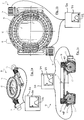
- the Fig. 1a shows a perspective view of a rotary indexing table 10 which, in the embodiment specifically illustrated here, has an annular output flange 12 or rotary plate 12, which is driven by two motors 14 to make a rotary movement.
- the output flange 12 can also be driven in a manner known per se via only a single motor or via more than two motors.
- the output flange 12 is annular and encloses a central opening 16 in which, for example, one or more processing machines for processing workpieces fastened on the turntable 12 can be located.
- FIG. 1b essentially shows the embodiment of FIG Fig. 1a in a plan view, wherein the dashed lines can be seen drivers 18, which can be designed, for example, as roller bolts and on the - in the position of use - the lower side of the output flange 12 are drivingly connected to this. Only the motors 14 are dimensioned differently than those in FIG Fig. 1a motors 14 shown.
- the drivers 18 and in particular the cam rollers 48 rotatably mounted on them engage in drive grooves 20 which are formed in cam drums 22 driven by the two motors 14 to rotate.
- the rotary movements of the cam drums 22 entrain the drivers 18, which engage in the drive grooves 20 spiraling around the cam drums 22, as a result of which the turntable 12 is driven to rotate.
- the drive grooves 20 thus form a mechanical control curve, since their slope determines, among other things, the movement profile of the turntable 12.
- the motors 14 and the cam drums 22 can be arranged coaxially. In the present embodiment, however, a transmission (not shown) is interposed in order to reduce a drive speed of the motors 14 (indirect drive).
- a preferred embodiment provides for the use of synchronous motors.
- the two motors 14 are connected in parallel and supplied with power by a common control device 30 on the basis of a motor control curve 32, which can be stored in a programmable memory 34 of the control device 30.
- the motor control curve 32 can specify an angle of rotation ⁇ of each motor 14, the angle of rotation ⁇ changing continuously as a function of time; for example, the engine control curve 32 have a bell-shaped varying angle of rotation profile.
- the motor control curve 32 is dependent on the time and indicates the angle of rotation ⁇ of the motor 14, which is required so that the output flange 12 covers a certain distance or angle as a function of time.
- the drive grooves 20, which are formed in the cam drums 22, also have a variable, ie a non-constant slope, even if this is particularly the case here Figure 1b cannot be clearly recognized.
- the current is supplied to the motors 14 on the basis of the motor control curve 32, in that the actual angle of rotation of the respective motor 14 is recorded by means of a rotary encoder (not shown) and compared to the time-dependent target angle of rotation ⁇ according to the motor control curve 32, so that this comparison is based on this the current supplied to the motor 14 can be regulated by the control device 30.
- the rotational movement of the output flange 12 is composed of two movement components that are simultaneously superimposed: see above One movement component of the output flange 12 is based on the gradient of the rotating drive groove 20 and a second movement component is based on the current supply to the motors 14, which varies on the basis of the motor control curve 32.
- both the slope of the drive grooves 20 is variable at least in some areas and the motor control curve 32 also has a variable slope at least in some areas
- the simultaneous superimposition of the movement component based on an area of variable slope of the drive grooves 20 and the movement component based on an area variable slope of the motor control curve 32 achieve a desired movement profile of the output flange 12, which can be as complex as desired.
- an optimization can be made of the movement profile of the output flange 12 by varying the motor control cam 32.
- a linear transport system 40 for use in, for example, a linear assembly system.
- the illustrated linear transport system 40 has a workpiece carrier 42 as a transport element, which is mounted on a rail 44 by means of rollers 46 so that the workpiece carrier 42 can be moved along the rail 44 to different assembly stations that are along the linear transport system 40 or the rail 44 are arranged. If the individual assembly stations are further apart, the workpiece carriers 42 can be moved between the individual assembly stations at high speed by means of a linear motor arrangement (not shown).
- the workpiece carrier 42 is driven in the region of the assembly station with high precision via a cam drum 22 which extends along the rail 44 and is driven by a motor 14 via a gear 50.
- the rotary movement of the cam drum 22 is converted into a longitudinal movement of the workpiece carrier 42 in that a driver 18 provided on the side of the workpiece carrier 42 and in particular its cam roller 48 engages in a drive groove 20 which is formed in the cam drum 22 and surrounds it in a spiral shape.
- the rotary movement of the cam drum 22 thus entrains the driver 18, which engages in the drive groove 20 which is spirally surrounded by the cam drum, whereby the workpiece carrier 42 is moved along the rail 44.
- the drive groove 20 has a slope which changes continuously over the entire length of the cam drum 22.
- the energization of the motor 14 takes place here again by means of a control device 30 on the basis of a motor control curve 32, which in a programmable Memory 34 of the control device 30 is stored.
- the motor control curve 32 is dependent on the time and indicates the angle of rotation ⁇ of the motor 14, which is required so that the workpiece carrier 42 covers a certain distance or stroke as a function of time.
- the current is supplied to the motor 14 on the basis of the motor control curve 32 in that the actual angle of rotation of the motor 14 is detected by means of a rotary encoder (not shown) and compared to the time-dependent target angle of rotation ⁇ according to the motor control curve 32, so that on the basis of this comparison of the control device 30 of the current supplied to the motor 14 can be regulated.
- the slope of the motor control curve 32 is variable over its entire temporal course and in particular has an angle of rotation course that varies in the manner of a bell curve;
- the motor control cam 32 can also only have a variable slope in some areas, provided that the slope of the drive groove 20 also changes at the same time.
- a desired movement profile of the workpiece carrier 42 can be achieved, which can be as complex as desired .
Claims (9)
- Dispositif de transport comportant un élément de transport apte à recevoir une pièce à usiner et déplaçable par un moteur (14) de manière rotative et/ou linéaire depuis une première position de repos jusque dans une deuxième position de repos, l'élément de transport étant relié en termes d'entraînement à au moins un doigt entraîneur (18) qui s'engage dans une rainure d'entraînement (20) d'un tambour à cames (22) pouvant être entraîné par le moteur (14) qui peut être piloté à l'aide d'un dispositif de commande programmable (30) sur la base d'une courbe de commande de moteur (34),
caractérisé en ce que
la rainure d'entraînement (20) présente une pente variable au moins localement, et en ce que
la courbe de commande de moteur (32) présente également une pente variable au moins localement, le mouvement de l'élément de transport résultant d'une superposition simultanée d'une première composante de mouvement, qui est basée sur une zone à pente variable de la rainure d'entraînement (20), et d'une deuxième composante de mouvement, qui est basée sur une zone à pente variable de la courbe de commande de moteur (32). - Dispositif de transport selon la revendication 1,
caractérisé en ce que
le moteur (14) peut être piloté sur la base d'une zone à pente variable de la courbe de commande de moteur (32), tandis que ledit au moins un doigt entraîneur (18) se trouve dans une zone à pente variable de la rainure d'entraînement (20). - Dispositif de transport de la revendication 1 ou 2,
caractérisé en ce que
ledit au moins un doigt entraîneur (18) est situé dans une zone à pente variable de la rainure d'entraînement (20) pendant qu'une zone à pente variable de la courbe de commande de moteur (32) est active pour piloter le moteur (14). - Dispositif de transport selon l'une au moins des revendications précédentes,
caractérisé en ce que
la courbe de commande de moteur (32) spécifie un angle de rotation (ϕ) du moteur (14) dépendant du temps pour obtenir un profil de mouvement souhaité de l'élément de transport. - Dispositif de transport selon l'une au moins des revendications précédentes,
caractérisé en ce que
la rainure d'entraînement (20) ne présente pas de phase d'arrêt, ni à un emplacement correspondant à la première position de repos, ni à un emplacement correspondant à la deuxième position de repos, ni entre les deux. - Dispositif de transport selon l'une au moins des revendications précédentes,
caractérisé en ce que
la pente de la rainure d'entraînement (20) est variable entre un emplacement de la rainure d'entraînement correspondant à la première position de repos et un emplacement de la rainure d'entraînement (20) correspondant à la deuxième position de repos, et en particulier elle ne présente pas de zones à pente constante. - Dispositif de transport selon l'une au moins des revendications précédentes,
caractérisé en ce que
la courbe de commande de moteur (32) est variable entre un emplacement correspondant à la première position de repos et un emplacement correspondant à la deuxième position de repos, et en particulier elle ne présente pas de zones de courbe à pente constante. - Dispositif de transport selon l'une au moins des revendications précédentes,
caractérisé en ce que
l'élément de transport est un porte-pièce (42) d'un système de transport linéaire (40), qui est guidé le long d'un rail (44) du système de transport linéaire (40). - Dispositif de transport selon l'une au moins des revendications 1 à 7,
caractérisé en ce que
l'élément de transport est un plateau tournant (12) d'une table à transfert circulaire (10).
Priority Applications (1)
| Application Number | Priority Date | Filing Date | Title |
|---|---|---|---|
| PL18743431T PL3602217T3 (pl) | 2017-07-20 | 2018-07-10 | Urządzenie transportowe do obrotowego i/lub liniowego przemieszczania przedmiotu obrabianego |
Applications Claiming Priority (2)
| Application Number | Priority Date | Filing Date | Title |
|---|---|---|---|
| DE102017116414.6A DE102017116414A1 (de) | 2017-07-20 | 2017-07-20 | Transportvorrichtung zur rotatorischen und/oder linearen bewegung eines werkstücks |
| PCT/EP2018/068703 WO2019016038A1 (fr) | 2017-07-20 | 2018-07-10 | Dispositif de transport permettant un déplacement rotatif et/ou linéaire d'une pièce |
Publications (2)
| Publication Number | Publication Date |
|---|---|
| EP3602217A1 EP3602217A1 (fr) | 2020-02-05 |
| EP3602217B1 true EP3602217B1 (fr) | 2021-03-24 |
Family
ID=62981183
Family Applications (1)
| Application Number | Title | Priority Date | Filing Date |
|---|---|---|---|
| EP18743431.1A Active EP3602217B1 (fr) | 2017-07-20 | 2018-07-10 | Dispositif de transport permettant un déplacement rotatif et/ou linéaire d'une pièce |
Country Status (10)
| Country | Link |
|---|---|
| US (1) | US10987773B2 (fr) |
| EP (1) | EP3602217B1 (fr) |
| KR (1) | KR102311543B1 (fr) |
| CN (1) | CN110869862B (fr) |
| BR (1) | BR112019023413A2 (fr) |
| CA (1) | CA3063802C (fr) |
| DE (1) | DE102017116414A1 (fr) |
| DK (1) | DK3602217T3 (fr) |
| PL (1) | PL3602217T3 (fr) |
| WO (1) | WO2019016038A1 (fr) |
Families Citing this family (3)
| Publication number | Priority date | Publication date | Assignee | Title |
|---|---|---|---|---|
| CN112357482A (zh) * | 2020-11-06 | 2021-02-12 | 安徽芜湖宝丰输送机械有限公司 | 一种等量均匀配送式自动运输设备 |
| CN112357481A (zh) * | 2020-11-06 | 2021-02-12 | 博众精工科技股份有限公司 | 一种托盘输送线体 |
| CN112548245B (zh) * | 2020-12-26 | 2022-02-08 | 景荣精密模具(深圳)有限公司 | 一种线切割机 |
Citations (12)
| Publication number | Priority date | Publication date | Assignee | Title |
|---|---|---|---|---|
| GB1477821A (en) | 1975-04-16 | 1977-06-29 | Rino Berardi Spa Off Mec | Device for controlling the relative motions of two structural members or components particularly in machine tools |
| EP0366594A2 (fr) | 1988-10-26 | 1990-05-02 | Emerson Electric Co. | Actionneur linéaire à came |
| EP0620080A1 (fr) | 1993-03-18 | 1994-10-19 | SIM ZUFÜHR-UND Montagetechnik GmbH & CO.KG | Dispositif pour le transport et le positionnement de porte-pièces, réalisé comme unité de déplacement linéaire |
| US5644950A (en) | 1995-11-17 | 1997-07-08 | Norco, Inc. | Heavy-duty mechanical oscillator |
| DE10162178A1 (de) | 2001-12-18 | 2003-07-03 | Abb Patent Gmbh | Hebevorrichtung zum Bewegen von Lasten |
| US20040144191A1 (en) | 2002-10-22 | 2004-07-29 | Sankyo Seisakusho Co | Inclining and rotating table apparatus |
| JP2006077842A (ja) | 2004-09-08 | 2006-03-23 | Sankyo Mfg Co Ltd | 駆動機構及びこれを用いた移動テーブル |
| DE102005038663A1 (de) | 2005-08-16 | 2007-02-22 | Weiss Gmbh Sondermaschinentechnik | Rundschalttisch |
| DE102007021681B3 (de) | 2007-05-09 | 2008-09-11 | Tünkers Maschinenbau Gmbh | Schrittschaltdrehtisch |
| DE102009049618A1 (de) | 2009-10-16 | 2011-04-21 | Weiß GmbH Sondermaschinentechnik | Rundschalttisch |
| US20130206514A1 (en) | 2010-08-06 | 2013-08-15 | Coreeelevator Co., Ltd. | Wormgear shaped driving part, elevator using wormgear shaped driving part and elevating system |
| EP3064417A1 (fr) | 2015-03-03 | 2016-09-07 | Expert-Tünkers GmbH | Dispositif de transport destine a deplacer des pieces de composant de carrosserie de l'industrie automobile |
Family Cites Families (18)
| Publication number | Priority date | Publication date | Assignee | Title |
|---|---|---|---|---|
| US3682005A (en) * | 1970-03-30 | 1972-08-08 | Umc Ind | Double cam drive |
| DE2035462C3 (de) * | 1970-07-17 | 1973-09-27 | Volkswagenwerk Ag, 3180 Wolfsburg | Steuerungsanordnung mit einem ein Maschinenteil einer Kraft oder Arbeite maschine penodisch bewegenden Nocken und einer Schwingungsdämpfung |
| US3850051A (en) * | 1972-09-01 | 1974-11-26 | Umc Ind | Precision functioning variable speed indexing apparatus |
| US4496280A (en) * | 1982-12-22 | 1985-01-29 | Brems John Henry | Workpiece transfer mechanism |
| US4704152A (en) * | 1986-07-28 | 1987-11-03 | Owens-Illinois, Inc. | Method of and apparatus for press forming cathode ray tube faceplate panels |
| FR2614818B2 (fr) | 1987-05-05 | 1990-03-02 | Dejoux Andre | Dispositif de guidage et d'entrainement d'organes mecaniques mobiles a deplacement notamment lineaire |
| KR100635008B1 (ko) | 2006-06-30 | 2006-10-16 | 서동식 | 회동 및 요동 병행 배럴캠 및 이를 이용한 인덱스 장치 |
| ES2378000T3 (es) * | 2008-02-25 | 2012-04-04 | EXPERT-TÜNKERS GmbH | Mesa giratoria con una unidad de control o regulación asociada |
| DE102009023079A1 (de) * | 2009-05-28 | 2010-12-02 | Weiß GmbH Sondermaschinentechnik | Rundschalttisch |
| CN102712069A (zh) * | 2009-10-16 | 2012-10-03 | 韦斯有限公司 | 具有输送凸轮的直接驱动装置的圆分度工作台 |
| DE102010013526A1 (de) * | 2010-03-31 | 2011-10-06 | Weiß GmbH Sondermaschinentechnik | Verfahren zur rotatorischen und/oder linearen Bewegung eines Werkstücks |
| DE102010013527A1 (de) * | 2010-03-31 | 2011-10-06 | Weiß GmbH Sondermaschinentechnik | Verfahren zur schwingungsgedämpften Bewegung eines Werkstücks |
| DE102010018003A1 (de) * | 2010-04-23 | 2011-10-27 | Weiß GmbH Sondermaschinentechnik | Verfahren zum Betrieb eines Schwenkantriebs |
| US8720289B2 (en) * | 2011-01-05 | 2014-05-13 | General Dynamics Ordnance And Tactical Systems, Inc. | Loading machine for feeding a receiver |
| DE102011107467A1 (de) * | 2011-07-08 | 2013-01-10 | Ingenieurbüro IKS Neufeld | Rundtaktmaschine |
| DE112014005544A5 (de) * | 2013-12-06 | 2016-09-29 | Schaeffler Technologies AG & Co. KG | Aktuator mit einem eine Drehbewegung in eine lineare Bewegung umwandelnden Getriebe |
| DE102014107654A1 (de) * | 2014-05-30 | 2015-12-03 | Weiss Gmbh | Antriebseinheit |
| DE102015013651B4 (de) * | 2015-10-22 | 2019-02-07 | EXPERT-TÜNKERS GmbH | Doppelwalzendrehtisch |
-
2017
- 2017-07-20 DE DE102017116414.6A patent/DE102017116414A1/de active Pending
-
2018
- 2018-07-10 PL PL18743431T patent/PL3602217T3/pl unknown
- 2018-07-10 BR BR112019023413-6A patent/BR112019023413A2/pt unknown
- 2018-07-10 DK DK18743431.1T patent/DK3602217T3/da active
- 2018-07-10 KR KR1020207004802A patent/KR102311543B1/ko active IP Right Grant
- 2018-07-10 US US16/632,049 patent/US10987773B2/en active Active
- 2018-07-10 EP EP18743431.1A patent/EP3602217B1/fr active Active
- 2018-07-10 CN CN201880032839.XA patent/CN110869862B/zh active Active
- 2018-07-10 CA CA3063802A patent/CA3063802C/fr active Active
- 2018-07-10 WO PCT/EP2018/068703 patent/WO2019016038A1/fr unknown
Patent Citations (15)
| Publication number | Priority date | Publication date | Assignee | Title |
|---|---|---|---|---|
| GB1477821A (en) | 1975-04-16 | 1977-06-29 | Rino Berardi Spa Off Mec | Device for controlling the relative motions of two structural members or components particularly in machine tools |
| EP0366594A2 (fr) | 1988-10-26 | 1990-05-02 | Emerson Electric Co. | Actionneur linéaire à came |
| EP0620080A1 (fr) | 1993-03-18 | 1994-10-19 | SIM ZUFÜHR-UND Montagetechnik GmbH & CO.KG | Dispositif pour le transport et le positionnement de porte-pièces, réalisé comme unité de déplacement linéaire |
| US5644950A (en) | 1995-11-17 | 1997-07-08 | Norco, Inc. | Heavy-duty mechanical oscillator |
| DE10162178A1 (de) | 2001-12-18 | 2003-07-03 | Abb Patent Gmbh | Hebevorrichtung zum Bewegen von Lasten |
| US20040144191A1 (en) | 2002-10-22 | 2004-07-29 | Sankyo Seisakusho Co | Inclining and rotating table apparatus |
| EP1413387B1 (fr) | 2002-10-24 | 2006-01-18 | Sankyo Seisakusho Co. | Système linéaire d'entraînement à came et suiveurs de came |
| DE60303266T2 (de) | 2002-10-24 | 2006-09-28 | Sankyo Seisakusho Co. | Lineares Antriebsystem mit Nocken und Nockenfolgern |
| JP2006077842A (ja) | 2004-09-08 | 2006-03-23 | Sankyo Mfg Co Ltd | 駆動機構及びこれを用いた移動テーブル |
| DE102005038663A1 (de) | 2005-08-16 | 2007-02-22 | Weiss Gmbh Sondermaschinentechnik | Rundschalttisch |
| DE102007021681B3 (de) | 2007-05-09 | 2008-09-11 | Tünkers Maschinenbau Gmbh | Schrittschaltdrehtisch |
| DE102009049618A1 (de) | 2009-10-16 | 2011-04-21 | Weiß GmbH Sondermaschinentechnik | Rundschalttisch |
| US20130206514A1 (en) | 2010-08-06 | 2013-08-15 | Coreeelevator Co., Ltd. | Wormgear shaped driving part, elevator using wormgear shaped driving part and elevating system |
| EP3064417A1 (fr) | 2015-03-03 | 2016-09-07 | Expert-Tünkers GmbH | Dispositif de transport destine a deplacer des pieces de composant de carrosserie de l'industrie automobile |
| DE102015002928A1 (de) | 2015-03-03 | 2016-09-08 | EXPERT-TÜNKERS GmbH | Transportvorrichtung zum Bewegen von Werkstücken, zum Beispiel für den Karosseriebau der Kfz-Industrie |
Non-Patent Citations (5)
| Title |
|---|
| ANONYMOUS: "DREHEN POSITIONIEREN TAKTEN AUTOMATION IN ALLEN DIMENSIONEN", TÜNKERS KATALOG DREHEN POSITIONIEREN TAKTEN, TÜNKERS MASCHINENBAU GMBH, 1 January 2019 (2019-01-01), pages 1 - 31, XP093141091, Retrieved from the Internet <URL:https://www.tuenkers.de/publish/binarydata/Service/download/katalog-expert-doppelseite.pdf> [retrieved on 20240313] |
| ANONYMOUS: "Drehen", FLYER TÜNKERS, TÜNKERS MASCHINENBAU GMBH, 1 July 2017 (2017-07-01), pages 1 - 3, XP093141087, Retrieved from the Internet <URL:https://www.tuenkers.de/publish/binarydata/Service/Praesentationen/2018/deutsch/07-tuenkers-imageflyer-drehen-d.pdf> [retrieved on 20240313] |
| ANONYMOUS: "Neun Module der Automation", TÜNKERS KATALOGE, TÜNKERS MASCHINENBAU GMBH, 1 April 2017 (2017-04-01), pages 1 - 390, XP093141221, Retrieved from the Internet <URL:https://www.expert-tuenkers.de/publish/binarydata/Download/Kataloge/expert_tuenkers_neun_komplett.pdf> [retrieved on 20240314] |
| ANONYMOUS: "Schnelles Takten und Positionieren", TÜNKERS KATALOGE, EXPERT-TÜNKERS GMBH, 1 September 2012 (2012-09-01), pages 1 - 109, XP093141220, Retrieved from the Internet <URL:https://www.expert-tuenkers.de/publish/binarydata/Download/Kataloge/katalog-takten-und-positionieren-kl.pdf> [retrieved on 20240314] |
| ANONYMOUS: "Taken und positioneren ", 1 October 2012 (2012-10-01), pages 1 - 9, XP093156353, Retrieved from the Internet <URL:https://tuenkers.com.br/wp-content/uploads/2017/07/edx-series-06-12-2012.pdf> [retrieved on 20240426] |
Also Published As
| Publication number | Publication date |
|---|---|
| US20200230763A1 (en) | 2020-07-23 |
| EP3602217A1 (fr) | 2020-02-05 |
| KR102311543B1 (ko) | 2021-10-08 |
| US10987773B2 (en) | 2021-04-27 |
| DK3602217T3 (da) | 2021-05-03 |
| CN110869862A (zh) | 2020-03-06 |
| PL3602217T3 (pl) | 2021-09-27 |
| CA3063802C (fr) | 2023-01-03 |
| DE102017116414A1 (de) | 2019-01-24 |
| CN110869862B (zh) | 2022-12-06 |
| BR112019023413A2 (pt) | 2020-06-16 |
| WO2019016038A1 (fr) | 2019-01-24 |
| CA3063802A1 (fr) | 2019-12-09 |
| KR20200041879A (ko) | 2020-04-22 |
Similar Documents
| Publication | Publication Date | Title |
|---|---|---|
| EP3602217B1 (fr) | Dispositif de transport permettant un déplacement rotatif et/ou linéaire d'une pièce | |
| DE2936785C2 (fr) | ||
| EP2756893A1 (fr) | Appareil de traitement des matériaux, notamment une machine de déformage | |
| EP3066533B1 (fr) | Procédé d'usinage d'une pièce brute au moyen d'un outil | |
| DE102015111602A1 (de) | Werkzeugmaschine mit Schiebetür | |
| DE102010042086A1 (de) | Drehteller mit Indexiereinheit und Betriebsverfahren | |
| CH704221A2 (de) | Vorrichtung und Verfahren zum Umformen von hohlzylindrischen Körpern. | |
| DE60222101T2 (de) | Vorrichtung zum antreiben und damit hergestelltes spannwerkeug | |
| EP1571034B1 (fr) | Dispositif de réglage longitudinal pour un siège de véhicule | |
| EP2543474B1 (fr) | Machine de cadencement | |
| WO2011054540A2 (fr) | Procédé et dispositif de durcissement inductif de grandes pièces annulaires | |
| EP0264474B1 (fr) | Procédé de, et machine pour le brochage par rotation de pièces à symétrie de révolution | |
| WO2015000855A1 (fr) | Dispositif et procédé pour transférer un élément et système d'outil | |
| EP1516699B1 (fr) | Dispositif de préparation et/ou de montage | |
| EP1632444A1 (fr) | Dispositif pour le transport pas à pas des porte-pièces | |
| DE102010034359A1 (de) | Einrichtung zur Erzeugung einer Dreh- und Hubbewegung | |
| DE3436576A1 (de) | Beschickungs- und entnahmevorrichtung, insbesondere an pressen | |
| DE202013103426U1 (de) | Vorrichtung zur Erzeugung einer Bohrung in einem Werkstück oder eines Gewindes in einer Bohrung eines Werkstücks | |
| WO2004110667A1 (fr) | Dispositif de transfert menage sur une presse | |
| EP3641983B1 (fr) | Plateau rotatif comprenant un entraînement optimisé en force | |
| DE102010033997A1 (de) | Metall- oder Keramikpulver-Elektropresse und Steuerverfahren dafür | |
| DE3034469A1 (de) | Transportvorrichtung fuer werkstuecke | |
| DE102005059677B3 (de) | Anordnung und Verfahren zur Regulierung der Geschwindigkeit eines Werkstückträgers in kontinuierlich arbeitenden Montage- und Bearbeitungsautomaten mit Längstransfer | |
| DE2357050A1 (de) | Presse mit vorschubeinrichtung | |
| DE10257634A1 (de) | Transportvorrichtung |
Legal Events
| Date | Code | Title | Description |
|---|---|---|---|
| STAA | Information on the status of an ep patent application or granted ep patent |
Free format text: STATUS: UNKNOWN |
|
| STAA | Information on the status of an ep patent application or granted ep patent |
Free format text: STATUS: THE INTERNATIONAL PUBLICATION HAS BEEN MADE |
|
| PUAI | Public reference made under article 153(3) epc to a published international application that has entered the european phase |
Free format text: ORIGINAL CODE: 0009012 |
|
| STAA | Information on the status of an ep patent application or granted ep patent |
Free format text: STATUS: REQUEST FOR EXAMINATION WAS MADE |
|
| 17P | Request for examination filed |
Effective date: 20191025 |
|
| AK | Designated contracting states |
Kind code of ref document: A1 Designated state(s): AL AT BE BG CH CY CZ DE DK EE ES FI FR GB GR HR HU IE IS IT LI LT LU LV MC MK MT NL NO PL PT RO RS SE SI SK SM TR |
|
| AX | Request for extension of the european patent |
Extension state: BA ME |
|
| REG | Reference to a national code |
Ref country code: DE Ref legal event code: R079 Ref document number: 502018004477 Country of ref document: DE Free format text: PREVIOUS MAIN CLASS: G05B0019418000 Ipc: B23Q0001520000 |
|
| GRAP | Despatch of communication of intention to grant a patent |
Free format text: ORIGINAL CODE: EPIDOSNIGR1 |
|
| STAA | Information on the status of an ep patent application or granted ep patent |
Free format text: STATUS: GRANT OF PATENT IS INTENDED |
|
| RIC1 | Information provided on ipc code assigned before grant |
Ipc: B23Q 16/02 20060101ALI20200831BHEP Ipc: B23Q 1/52 20060101AFI20200831BHEP Ipc: F16H 53/02 20060101ALI20200831BHEP Ipc: B23Q 7/02 20060101ALI20200831BHEP |
|
| DAV | Request for validation of the european patent (deleted) | ||
| DAX | Request for extension of the european patent (deleted) | ||
| INTG | Intention to grant announced |
Effective date: 20201002 |
|
| GRAS | Grant fee paid |
Free format text: ORIGINAL CODE: EPIDOSNIGR3 |
|
| GRAA | (expected) grant |
Free format text: ORIGINAL CODE: 0009210 |
|
| STAA | Information on the status of an ep patent application or granted ep patent |
Free format text: STATUS: THE PATENT HAS BEEN GRANTED |
|
| AK | Designated contracting states |
Kind code of ref document: B1 Designated state(s): AL AT BE BG CH CY CZ DE DK EE ES FI FR GB GR HR HU IE IS IT LI LT LU LV MC MK MT NL NO PL PT RO RS SE SI SK SM TR |
|
| REG | Reference to a national code |
Ref country code: GB Ref legal event code: FG4D Free format text: NOT ENGLISH |
|
| REG | Reference to a national code |
Ref country code: CH Ref legal event code: EP |
|
| REG | Reference to a national code |
Ref country code: DE Ref legal event code: R096 Ref document number: 502018004477 Country of ref document: DE |
|
| REG | Reference to a national code |
Ref country code: IE Ref legal event code: FG4D Free format text: LANGUAGE OF EP DOCUMENT: GERMAN |
|
| REG | Reference to a national code |
Ref country code: AT Ref legal event code: REF Ref document number: 1373998 Country of ref document: AT Kind code of ref document: T Effective date: 20210415 Ref country code: CH Ref legal event code: NV Representative=s name: INTELLECTUAL PROPERTY SERVICES GMBH, CH |
|
| REG | Reference to a national code |
Ref country code: DK Ref legal event code: T3 Effective date: 20210428 |
|
| REG | Reference to a national code |
Ref country code: FI Ref legal event code: FGE |
|
| REG | Reference to a national code |
Ref country code: NL Ref legal event code: FP |
|
| REG | Reference to a national code |
Ref country code: LT Ref legal event code: MG9D |
|
| PG25 | Lapsed in a contracting state [announced via postgrant information from national office to epo] |
Ref country code: BG Free format text: LAPSE BECAUSE OF FAILURE TO SUBMIT A TRANSLATION OF THE DESCRIPTION OR TO PAY THE FEE WITHIN THE PRESCRIBED TIME-LIMIT Effective date: 20210624 Ref country code: GR Free format text: LAPSE BECAUSE OF FAILURE TO SUBMIT A TRANSLATION OF THE DESCRIPTION OR TO PAY THE FEE WITHIN THE PRESCRIBED TIME-LIMIT Effective date: 20210625 Ref country code: HR Free format text: LAPSE BECAUSE OF FAILURE TO SUBMIT A TRANSLATION OF THE DESCRIPTION OR TO PAY THE FEE WITHIN THE PRESCRIBED TIME-LIMIT Effective date: 20210324 Ref country code: NO Free format text: LAPSE BECAUSE OF FAILURE TO SUBMIT A TRANSLATION OF THE DESCRIPTION OR TO PAY THE FEE WITHIN THE PRESCRIBED TIME-LIMIT Effective date: 20210624 |
|
| REG | Reference to a national code |
Ref country code: DE Ref legal event code: R026 Ref document number: 502018004477 Country of ref document: DE |
|
| PLBI | Opposition filed |
Free format text: ORIGINAL CODE: 0009260 |
|
| PG25 | Lapsed in a contracting state [announced via postgrant information from national office to epo] |
Ref country code: LV Free format text: LAPSE BECAUSE OF FAILURE TO SUBMIT A TRANSLATION OF THE DESCRIPTION OR TO PAY THE FEE WITHIN THE PRESCRIBED TIME-LIMIT Effective date: 20210324 Ref country code: RS Free format text: LAPSE BECAUSE OF FAILURE TO SUBMIT A TRANSLATION OF THE DESCRIPTION OR TO PAY THE FEE WITHIN THE PRESCRIBED TIME-LIMIT Effective date: 20210324 Ref country code: SE Free format text: LAPSE BECAUSE OF FAILURE TO SUBMIT A TRANSLATION OF THE DESCRIPTION OR TO PAY THE FEE WITHIN THE PRESCRIBED TIME-LIMIT Effective date: 20210324 |
|
| REG | Reference to a national code |
Ref country code: FI Ref legal event code: MDE Opponent name: EXPERT-TUENKERS GMBH |
|
| 26 | Opposition filed |
Opponent name: EXPERT-TUENKERS GMBH Effective date: 20210809 |
|
| PG25 | Lapsed in a contracting state [announced via postgrant information from national office to epo] |
Ref country code: CZ Free format text: LAPSE BECAUSE OF FAILURE TO SUBMIT A TRANSLATION OF THE DESCRIPTION OR TO PAY THE FEE WITHIN THE PRESCRIBED TIME-LIMIT Effective date: 20210324 Ref country code: EE Free format text: LAPSE BECAUSE OF FAILURE TO SUBMIT A TRANSLATION OF THE DESCRIPTION OR TO PAY THE FEE WITHIN THE PRESCRIBED TIME-LIMIT Effective date: 20210324 Ref country code: LT Free format text: LAPSE BECAUSE OF FAILURE TO SUBMIT A TRANSLATION OF THE DESCRIPTION OR TO PAY THE FEE WITHIN THE PRESCRIBED TIME-LIMIT Effective date: 20210324 Ref country code: SM Free format text: LAPSE BECAUSE OF FAILURE TO SUBMIT A TRANSLATION OF THE DESCRIPTION OR TO PAY THE FEE WITHIN THE PRESCRIBED TIME-LIMIT Effective date: 20210324 |
|
| PG25 | Lapsed in a contracting state [announced via postgrant information from national office to epo] |
Ref country code: IS Free format text: LAPSE BECAUSE OF FAILURE TO SUBMIT A TRANSLATION OF THE DESCRIPTION OR TO PAY THE FEE WITHIN THE PRESCRIBED TIME-LIMIT Effective date: 20210724 Ref country code: RO Free format text: LAPSE BECAUSE OF FAILURE TO SUBMIT A TRANSLATION OF THE DESCRIPTION OR TO PAY THE FEE WITHIN THE PRESCRIBED TIME-LIMIT Effective date: 20210324 Ref country code: PT Free format text: LAPSE BECAUSE OF FAILURE TO SUBMIT A TRANSLATION OF THE DESCRIPTION OR TO PAY THE FEE WITHIN THE PRESCRIBED TIME-LIMIT Effective date: 20210726 Ref country code: SK Free format text: LAPSE BECAUSE OF FAILURE TO SUBMIT A TRANSLATION OF THE DESCRIPTION OR TO PAY THE FEE WITHIN THE PRESCRIBED TIME-LIMIT Effective date: 20210324 |
|
| PLAX | Notice of opposition and request to file observation + time limit sent |
Free format text: ORIGINAL CODE: EPIDOSNOBS2 |
|
| PG25 | Lapsed in a contracting state [announced via postgrant information from national office to epo] |
Ref country code: AL Free format text: LAPSE BECAUSE OF FAILURE TO SUBMIT A TRANSLATION OF THE DESCRIPTION OR TO PAY THE FEE WITHIN THE PRESCRIBED TIME-LIMIT Effective date: 20210324 Ref country code: ES Free format text: LAPSE BECAUSE OF FAILURE TO SUBMIT A TRANSLATION OF THE DESCRIPTION OR TO PAY THE FEE WITHIN THE PRESCRIBED TIME-LIMIT Effective date: 20210324 |
|
| PG25 | Lapsed in a contracting state [announced via postgrant information from national office to epo] |
Ref country code: SI Free format text: LAPSE BECAUSE OF FAILURE TO SUBMIT A TRANSLATION OF THE DESCRIPTION OR TO PAY THE FEE WITHIN THE PRESCRIBED TIME-LIMIT Effective date: 20210324 |
|
| PLBB | Reply of patent proprietor to notice(s) of opposition received |
Free format text: ORIGINAL CODE: EPIDOSNOBS3 |
|
| PG25 | Lapsed in a contracting state [announced via postgrant information from national office to epo] |
Ref country code: MC Free format text: LAPSE BECAUSE OF FAILURE TO SUBMIT A TRANSLATION OF THE DESCRIPTION OR TO PAY THE FEE WITHIN THE PRESCRIBED TIME-LIMIT Effective date: 20210324 |
|
| REG | Reference to a national code |
Ref country code: BE Ref legal event code: MM Effective date: 20210731 |
|
| PG25 | Lapsed in a contracting state [announced via postgrant information from national office to epo] |
Ref country code: IS Free format text: LAPSE BECAUSE OF FAILURE TO SUBMIT A TRANSLATION OF THE DESCRIPTION OR TO PAY THE FEE WITHIN THE PRESCRIBED TIME-LIMIT Effective date: 20210724 Ref country code: LU Free format text: LAPSE BECAUSE OF NON-PAYMENT OF DUE FEES Effective date: 20210710 |
|
| PG25 | Lapsed in a contracting state [announced via postgrant information from national office to epo] |
Ref country code: IE Free format text: LAPSE BECAUSE OF NON-PAYMENT OF DUE FEES Effective date: 20210710 Ref country code: BE Free format text: LAPSE BECAUSE OF NON-PAYMENT OF DUE FEES Effective date: 20210731 |
|
| PG25 | Lapsed in a contracting state [announced via postgrant information from national office to epo] |
Ref country code: CY Free format text: LAPSE BECAUSE OF FAILURE TO SUBMIT A TRANSLATION OF THE DESCRIPTION OR TO PAY THE FEE WITHIN THE PRESCRIBED TIME-LIMIT Effective date: 20210324 |
|
| P01 | Opt-out of the competence of the unified patent court (upc) registered |
Effective date: 20230525 |
|
| PG25 | Lapsed in a contracting state [announced via postgrant information from national office to epo] |
Ref country code: HU Free format text: LAPSE BECAUSE OF FAILURE TO SUBMIT A TRANSLATION OF THE DESCRIPTION OR TO PAY THE FEE WITHIN THE PRESCRIBED TIME-LIMIT; INVALID AB INITIO Effective date: 20180710 |
|
| PGFP | Annual fee paid to national office [announced via postgrant information from national office to epo] |
Ref country code: PL Payment date: 20230629 Year of fee payment: 6 Ref country code: NL Payment date: 20230719 Year of fee payment: 6 |
|
| PGFP | Annual fee paid to national office [announced via postgrant information from national office to epo] |
Ref country code: IT Payment date: 20230724 Year of fee payment: 6 Ref country code: GB Payment date: 20230721 Year of fee payment: 6 Ref country code: FI Payment date: 20230719 Year of fee payment: 6 Ref country code: CH Payment date: 20230801 Year of fee payment: 6 Ref country code: AT Payment date: 20230720 Year of fee payment: 6 |
|
| PGFP | Annual fee paid to national office [announced via postgrant information from national office to epo] |
Ref country code: FR Payment date: 20230726 Year of fee payment: 6 Ref country code: DK Payment date: 20230721 Year of fee payment: 6 |
|
| PGFP | Annual fee paid to national office [announced via postgrant information from national office to epo] |
Ref country code: DE Payment date: 20230927 Year of fee payment: 6 |
|
| PLBD | Termination of opposition procedure: decision despatched |
Free format text: ORIGINAL CODE: EPIDOSNOPC1 |
|
| PLBP | Opposition withdrawn |
Free format text: ORIGINAL CODE: 0009264 |
|
| PG25 | Lapsed in a contracting state [announced via postgrant information from national office to epo] |
Ref country code: MK Free format text: LAPSE BECAUSE OF FAILURE TO SUBMIT A TRANSLATION OF THE DESCRIPTION OR TO PAY THE FEE WITHIN THE PRESCRIBED TIME-LIMIT Effective date: 20210324 |
|
| REG | Reference to a national code |
Ref country code: CH Ref legal event code: PK Free format text: DIE PUBLIKATION VOM 27.03.2024 WURDE AM 24.04.2024 IRRTUEMLICHERWEISE ERNEUT PUBLIZIERT. LA PUBLICATION DU 27.03.2024 A ETE REPUBLIEE PAR ERREUR LE 24.04.2024. LA PUBBLICAZIONE DEL 27.03.2024 E STATA ERRONEAMENTE RIPUBBLICATA IL 24.04.2024. |