EP3601065B1 - Trennvorrichtung für eine bandendverbindungsvorrichtung, bandendverbindungsvorrichtung und umreifungssystem - Google Patents
Trennvorrichtung für eine bandendverbindungsvorrichtung, bandendverbindungsvorrichtung und umreifungssystem Download PDFInfo
- Publication number
- EP3601065B1 EP3601065B1 EP18726616.8A EP18726616A EP3601065B1 EP 3601065 B1 EP3601065 B1 EP 3601065B1 EP 18726616 A EP18726616 A EP 18726616A EP 3601065 B1 EP3601065 B1 EP 3601065B1
- Authority
- EP
- European Patent Office
- Prior art keywords
- strap
- end connecting
- connecting device
- blade
- heating element
- Prior art date
- Legal status (The legal status is an assumption and is not a legal conclusion. Google has not performed a legal analysis and makes no representation as to the accuracy of the status listed.)
- Active
Links
Images




Classifications
-
- B—PERFORMING OPERATIONS; TRANSPORTING
- B65—CONVEYING; PACKING; STORING; HANDLING THIN OR FILAMENTARY MATERIAL
- B65B—MACHINES, APPARATUS OR DEVICES FOR, OR METHODS OF, PACKAGING ARTICLES OR MATERIALS; UNPACKING
- B65B13/00—Bundling articles
- B65B13/02—Applying and securing binding material around articles or groups of articles, e.g. using strings, wires, strips, bands or tapes
- B65B13/16—Applying and securing binding material around articles or groups of articles, e.g. using strings, wires, strips, bands or tapes with means for severing the binding material from supply and then applying it around the articles
-
- B—PERFORMING OPERATIONS; TRANSPORTING
- B65—CONVEYING; PACKING; STORING; HANDLING THIN OR FILAMENTARY MATERIAL
- B65B—MACHINES, APPARATUS OR DEVICES FOR, OR METHODS OF, PACKAGING ARTICLES OR MATERIALS; UNPACKING
- B65B13/00—Bundling articles
- B65B13/18—Details of, or auxiliary devices used in, bundling machines or bundling tools
- B65B13/24—Securing ends of binding material
- B65B13/32—Securing ends of binding material by welding, soldering, or heat-sealing; by applying adhesive
Definitions
- the conveying movement of the packaged good then brings it about that the strap bears against the front side of the second packaged good and against the two sides of the packaged good.
- Two assemblies of the strap end connecting device of which in each case one is arranged at this time on in each case one side of the respective packaged good, are then moved toward one another behind the packaged good.
- each of said two assemblies of the strap end connector guides one side of the strapping to be formed and moves it behind the packaged good.
- one of said two assemblies comprises a separating device for severing the two strapping sides from their strap supply.
- one of the two assemblies comprises a pressing unit, by way of which the two strap ends are brought into contact against one another.
- a strap end connector is previously known from DE 102 25 751 C5 , in the case of which strap end connector the heating device is configured as a vibration welding device which is assigned to one of the two assemblies.
- the heat which is required for melting of the plastic is introduced into the strap ends by means of welding elements which are pressed against the two strap ends and are moved to and fro in an alternating and vibrating manner.
- the other assembly is provided with a mechanical edge or blade which is moved into the two straps in order to sever the latter.
- the plastic straps are severed by way of a mechanical cutting operation.
- This solution has the disadvantage that it is not fully functionally reliable and, above all, relatively thick straps can cause difficulties in terms of being severed reliably.
- cutting of the strap and welding of the strap ends cannot take place in the same cycle without an additional lift.
- a strap end connecting device according to preamble of claim 1 is known from US 4209958 A .
- the invention is therefore based on the object of providing an improvement in the case of strap end connectors, by way of which improvement functionally reliable severing becomes possible even in the case of different strap thicknesses with maintenance of the severing means which is as low as possible.
- the separating device has a carrier, on which the blade is arranged, the carrier being provided for attaching or arranging on that assembly of the strap end connecting device which has the heating element.
- the blade is arranged in the vicinity of the heating element by means of the carrier; vicinity can be understood to mean a spacing, in the case of which, by means of the heating element, the blade experiences or can experience a temperature increase on account of the heating element despite a spacing between the heating element and the blade.
- a spacing between the heating element and the blade is preferably adjustable, for example by way of suitable structural measures. As a result, a temperature of the blade can be influenced in a targeted manner.
- the carrier can have positioning aids for arranging on the assembly which has the heating element.
- the carrier can be capable of being screwed to the assembly which has the heating element, in particular in a releasable manner. There should preferably not be direct physical contact between the blade and the heating element.
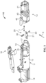
- the insulation block 18 with the heating element 17 which is fastened thereon can be moved to and fro transversely with respect to the conveying direction 6 and in the direction of the second fastening head 12 in and counter to a movement direction 7 of the fastening heads 11, 12.
- the blade 30 moves together with the heating element 17 relative to the housing 13 and parallel to the movement direction 7.
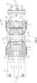
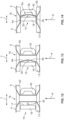
- Fig. 12 shows a diagrammatic illustration of the strap end connecting device 10 in an operating position which corresponds to a first method step and in which the first fastening head 11 and the second fastening head 12 are moved together completely.
- the strap clamp 6 fixes the straps 4, 5.
- the first strap 4 is clamped in fixedly between the housing 13 of the first fastening head 11 and the strap clamp 16.
- the second strap 5 is clamped in fixedly between the housing 40 of the second fastening head 12 and the strap clamp 16.
- the heating element 17 and the blade 30 which is heated by way of heat radiation are in a starting position.
- the edge 31 of the blade 30 is spaced apart from the two straps 4, 5.
- the first strap end 4a and the second strap end 4b of the first strap 4 are produced as a result.
- the two strap ends 4a, 4b of the first strap 4 are oriented parallel to the movement direction 7 and spaced apart from one another, and are placed from the inside onto the strap clamp 16.
- first strap end 5a and the second strap end 5b of the second strap 5 are oriented parallel to the movement direction 7, but in the opposite direction with respect to the strap ends 4a, 4b of the first strap 4 and spaced apart from one another, and are welded in each case to the associated strap ends 4a, 4b.
Landscapes
- Engineering & Computer Science (AREA)
- Mechanical Engineering (AREA)
- Basic Packing Technique (AREA)
Claims (7)
- Bandendverbindungseinrichtung (10) für ein Umreifungssystem (1), wobei die Bandendverbindungseinrichtung (10) mit zwei zusammenwirkenden Baugruppen, insbesondere mit zwei Verschlussköpfen (11, 12), die aufeinander zu und voneinander weg bewegbar sind und die zum Bilden von Umreifungen aus jeweils zwei Kunststoffbändern vorgesehen sind, einer Trenneinrichtung (20) zum Durchtrennen der zwei Kunststoffbänder und einer Schweißeinheit (15) zum Verschweißen von Bandenden (4a, 5a, 4b, 5b) der zwei Kunststoffbänder versehen ist, die in einer auf die zwei Baugruppen verteilten Weise bereitgestellt sind, wobei die Bandendverbindungseinrichtung (10) eine Trenneinrichtung (20) zum Durchtrennen mindestens eines Bandes (4, 5), insbesondere eines Kunststoffbandes, umfasst, wobei die Trenneinrichtung (20) eine Klinge (30) mit einer Kante (31) zum Durchtrennen des mindestens einen Bandes (4, 5) aufweist und die Trenneinrichtung dazu ausgelegt ist, mit der Bandendverbindungseinrichtung (10) verbunden zu sein, wobei die Bandendverbindungseinrichtung (10) eine Baugruppe aufweist, die ein Heizelement (17) aufweist, wobei die Klinge (30) dazu ausgelegt ist, mit der Baugruppe der Bandendverbindungseinrichtung (10), die das Heizelement (17) aufweist, verbunden zu sein, wobei die Trenneinrichtung (20) einen Träger (21) aufweist, auf dem die Klinge (30) angeordnet ist, wobei der Träger (21) dazu ausgelegt ist, an der Baugruppe der Bandendverbindungseinrichtung (10), die das Heizelement (17) aufweist, befestigt zu sein, und dadurch gekennzeichnet, dass ein Abstand zwischen dem Heizelement (17) und der Klinge (30) vorhanden ist, wobei das Heizelement (17) ein Bestandteil der Schweißeinheit (15) ist und wobei die Klinge mittels des Trägers (21) in der Nähe des Heizelements (17) angeordnet ist, so dass die Klinge (30) aufgrund des Heizelements (17) eine Temperaturerhöhung erfahren kann, wobei die Bandendverbindungseinrichtung (10) ferner ein Isolationsmittel umfasst, mittels dessen die Klinge (30) elektrisch von dem elektrisch erwärmten Heizelement (17) isoliert ist.
- Bandendverbindungseinrichtung (10) nach Anspruch 1, dadurch gekennzeichnet, dass die Bandendverbindungseinrichtung (10) eine erste Baugruppe, die dazu ausgelegt ist, mit der Trenneinrichtung (20) zum Erwärmen, insbesondere Schweißen, mindestens zweier miteinander zu verbindender Bandenden (4a, 5a, 4b, 5b) der Kunststoffbänder (4, 5) verbunden zu sein, und eine zweite Baugruppe zum Anlegen, insbesondere Anpressen, der miteinander zu verbindenden Bandenden (4a, 5a, 4b, 5b) aufweist.
- Bandendverbindungseinrichtung (10) nach den Ansprüchen 1 bis 2, dadurch gekennzeichnet, dass die Klinge (30) dazu ausgelegt ist, zusammen mit der Schweißeinheit (15) in Richtung einer Anpresseinheit (42) der zweiten Baugruppe vorgeschoben zu werden.
- Bandendverbindungseinrichtung (10) nach einem der Ansprüche 1 bis 3, dadurch gekennzeichnet, dass die Klinge (30) auf eine Betriebstemperatur, die höher als eine Umgebungstemperatur ist, insbesondere mittels durch das Heizelement (17) erzeugter Wärmestrahlung, vorzugsweise zumindest im Wesentlichen ausschließlich mittels durch das Heizelement (17) erzeugter Wärmestrahlung, erwärmt werden kann.
- Bandendverbindungseinrichtung (10) nach einem der Ansprüche 1 bis 4, ferner umfassend eine Bandklemme (16), die derart schwenkbar an einem ersten Verschlusskopf (11) der Verschlussköpfe (11, 12) befestigt ist, dass das erste Band (4) fest zwischen ein Gehäuse (13) des ersten Verschlusskopfs (11) und die Bandklemme (16) einklemmbar ist und die zweite Bandklemme (5) fest zwischen ein Gehäuse (40) eines zweiten Verschlusskopfs (12) der Verschlussköpfe (11, 12) und die Bandklemme (16) einklemmbar ist.
- Umreifungssystem (1), das ein Portal (2) und eine Zuführeinrichtung (3) zum Lagern und zum Bereitstellen zweier Bänder (4, 5) aufweist, wobei das Portal (2) mit einer Bandendverbindungseinrichtung versehen ist, gekennzeichnet durch eine Bandendverbindungseinrichtung (10) nach einem der Ansprüche 1 bis 5.
- Umreifungssystem (1) nach Anspruch 6, dadurch gekennzeichnet, dass ein erstes Band (4) und ein zweites Band (5) mittels der erwärmten Klinge (30) der Trenneinrichtung (20) der Bandendverbindungseinrichtung (10) durchtrennbar sind und in einem nachfolgenden Arbeitsschritt ein erstes Bandende (4a) des ersten Bandes (4) und ein erstes Bandende (5a) des zweiten Bandes (5) zum Bilden eines Verschlusses mittels der Bandendverbindungseinrichtung (10) miteinander verbunden werden können, wobei eine Umreifung vorzugsweise an zweiten Bandenden (4b, 5b) derselben Bänder (4, 5) mittels eines zweiten Verschlusses, der in der gleichen Weise mittels der Bandendverbindungseinrichtung (10) gebildet wird, hergestellt wird.
Applications Claiming Priority (2)
| Application Number | Priority Date | Filing Date | Title |
|---|---|---|---|
| CH00590/17A CH713945A2 (de) | 2017-05-03 | 2017-05-03 | Trenneinrichtung für eine Bandendverbindungseinrichtung, Bandendverbindungseinrichtung sowie Bandumreifungsanlage. |
| PCT/US2018/030367 WO2018204309A1 (en) | 2017-05-03 | 2018-05-01 | Separating device for a strap end connecting device, strap end connecting device, and strapping system |
Publications (2)
| Publication Number | Publication Date |
|---|---|
| EP3601065A1 EP3601065A1 (de) | 2020-02-05 |
| EP3601065B1 true EP3601065B1 (de) | 2025-04-16 |
Family
ID=64016569
Family Applications (1)
| Application Number | Title | Priority Date | Filing Date |
|---|---|---|---|
| EP18726616.8A Active EP3601065B1 (de) | 2017-05-03 | 2018-05-01 | Trennvorrichtung für eine bandendverbindungsvorrichtung, bandendverbindungsvorrichtung und umreifungssystem |
Country Status (5)
| Country | Link |
|---|---|
| US (1) | US11434030B2 (de) |
| EP (1) | EP3601065B1 (de) |
| CN (1) | CN110546073B (de) |
| CH (1) | CH713945A2 (de) |
| WO (1) | WO2018204309A1 (de) |
Citations (4)
| Publication number | Priority date | Publication date | Assignee | Title |
|---|---|---|---|---|
| US3316687A (en) * | 1964-02-06 | 1967-05-02 | Fmc Corp | Strap securing method |
| GB1502822A (en) * | 1975-03-27 | 1978-03-01 | Mvm Endra | Application of tape to a package |
| US4209958A (en) * | 1977-10-10 | 1980-07-01 | Bailey Peter E | Article strapping |
| DE4401508A1 (de) * | 1993-11-05 | 1995-05-11 | Pkm Maschinen Gmbh & Co Kg | Trenn- und Schweißvorrichtung als Teil einer Vorrichtung zum Umreifen von Packstücken mit einem verschweißbaren Band |
Family Cites Families (13)
| Publication number | Priority date | Publication date | Assignee | Title |
|---|---|---|---|---|
| US2837883A (en) * | 1956-09-06 | 1958-06-10 | Package Machinery Co | Automatic packaging machine |
| SE351592C (sv) * | 1972-03-29 | 1974-05-06 | Iwema Foerpacknings Ab | Svetsbackar för sammansvetsning av foliebanor |
| US4512138A (en) * | 1982-03-04 | 1985-04-23 | The Dow Chemical Company | Form, fill and seal machine with hot gas and thermal impulse sealing |
| NL8503373A (nl) | 1985-12-06 | 1987-07-01 | Endra Bv | Werkwijze en inrichting voor het aanbrengen van een draad, een band, folie of een ander buigzaam omsnoeringselement om een voorwerp of een reeks op of naast elkaar geplaatste voorwerpen. |
| US5226461A (en) * | 1991-11-18 | 1993-07-13 | General Motors Corporation | Strap crimp and crimping tool |
| JPH05246404A (ja) * | 1992-02-27 | 1993-09-24 | Toho Kikai Kogyo Kk | 結束機 |
| NL1006455C2 (nl) | 1997-07-02 | 1999-01-05 | Endra Bv | Bandomsnoeringsinrichting. |
| JP3781550B2 (ja) * | 1998-03-31 | 2006-05-31 | トッパン・フォームズ株式会社 | 単片用紙束の帯掛け装置におけるテープカット機構 |
| NL1019001C2 (nl) | 2001-09-20 | 2003-03-21 | Endra Bv | Werkwijze en inrichting voor het met een etikettenband omsnoeren van een of meer pakketten. |
| DE10225751C5 (de) | 2002-06-10 | 2013-09-19 | Anke Bauer-Berardi | Vorrichtung zum Anbringen eines Umreifungsbandes an einem Gegenstand oder einem Stapel von Gegenständen |
| NL1021798C2 (nl) | 2002-10-31 | 2004-05-07 | Endra Bv | Inrichting voor het aanbrengen van tenminste twee banden rond een of meer pakketten. |
| EA007697B1 (ru) * | 2003-01-24 | 2006-12-29 | Энтерпрайзиз Интернэшнл Инк. | Устройство и способы для наложения ленты вокруг пачки предметов |
| CN206107639U (zh) * | 2016-10-13 | 2017-04-19 | 上海蜀工自动化科技有限公司 | 一种换热器捆扎机铁丝剪断打结装置 |
-
2017
- 2017-05-03 CH CH00590/17A patent/CH713945A2/de unknown
-
2018
- 2018-05-01 EP EP18726616.8A patent/EP3601065B1/de active Active
- 2018-05-01 WO PCT/US2018/030367 patent/WO2018204309A1/en not_active Ceased
- 2018-05-01 CN CN201880027181.3A patent/CN110546073B/zh active Active
-
2019
- 2019-10-23 US US16/661,390 patent/US11434030B2/en active Active
Patent Citations (4)
| Publication number | Priority date | Publication date | Assignee | Title |
|---|---|---|---|---|
| US3316687A (en) * | 1964-02-06 | 1967-05-02 | Fmc Corp | Strap securing method |
| GB1502822A (en) * | 1975-03-27 | 1978-03-01 | Mvm Endra | Application of tape to a package |
| US4209958A (en) * | 1977-10-10 | 1980-07-01 | Bailey Peter E | Article strapping |
| DE4401508A1 (de) * | 1993-11-05 | 1995-05-11 | Pkm Maschinen Gmbh & Co Kg | Trenn- und Schweißvorrichtung als Teil einer Vorrichtung zum Umreifen von Packstücken mit einem verschweißbaren Band |
Also Published As
| Publication number | Publication date |
|---|---|
| US20200055621A1 (en) | 2020-02-20 |
| US11434030B2 (en) | 2022-09-06 |
| CH713945A2 (de) | 2019-01-15 |
| CN110546073A (zh) | 2019-12-06 |
| EP3601065A1 (de) | 2020-02-05 |
| WO2018204309A1 (en) | 2018-11-08 |
| CN110546073B (zh) | 2021-09-07 |
Similar Documents
| Publication | Publication Date | Title |
|---|---|---|
| US5161347A (en) | Cutting device for plastic netting | |
| EP3031561B1 (de) | Horizontale bandsägemaschine | |
| US8904925B2 (en) | Modular strapping head with heat blade | |
| KR101939977B1 (ko) | 스티로폼 절단기용 커팅부 구조 | |
| EP1228846B1 (de) | Verfahren und Vorrichtung zum Schneiden und Formen von Bandelementen aus Gummi | |
| US20140251101A1 (en) | Cross-cutting device | |
| RU2633953C1 (ru) | Устройство для установки сливного насадка | |
| JP2000500401A (ja) | カミソリ刃の製造 | |
| US4994137A (en) | Bag making machine sealer slitter apparatus | |
| US11434030B2 (en) | Separating device for a strap end connecting device, strap end connecting device, and strapping system | |
| EP1971524B1 (de) | Vorrichtung zum umreifen von waren | |
| CN102061607A (zh) | 化纤带裁断、冲孔方法及装置 | |
| US6915572B1 (en) | Method and plant for continuously producing construction | |
| CN209937035U (zh) | 一种橡胶剪切设备 | |
| JP2021000766A (ja) | 超音波フィルム巻き包装機 | |
| US8820227B2 (en) | Strapping machine for tying packages, in particular metal strips wound into coils | |
| CN215040427U (zh) | 口罩焊耳带机 | |
| CN210754882U (zh) | 一种金属片编织线焊接机构 | |
| EP1617988B1 (de) | Siegelvorrichtung zum versiegeln und gleichzeitigen schneiden einer materialbahn | |
| KR101980210B1 (ko) | 스터드 볼트 용접장치 | |
| CN206140002U (zh) | 锯片激光焊接机的刀头输送装置 | |
| KR101632905B1 (ko) | 연료탱크 지지밴드 제조시스템의 핀 공급장치 | |
| CN219259040U (zh) | 制带机构 | |
| AU2011271130B9 (en) | Modular strapping head with heat blade | |
| JP2913340B2 (ja) | ベニヤ単板の横矧方法及び装置 |
Legal Events
| Date | Code | Title | Description |
|---|---|---|---|
| STAA | Information on the status of an ep patent application or granted ep patent |
Free format text: STATUS: UNKNOWN |
|
| STAA | Information on the status of an ep patent application or granted ep patent |
Free format text: STATUS: THE INTERNATIONAL PUBLICATION HAS BEEN MADE |
|
| PUAI | Public reference made under article 153(3) epc to a published international application that has entered the european phase |
Free format text: ORIGINAL CODE: 0009012 |
|
| STAA | Information on the status of an ep patent application or granted ep patent |
Free format text: STATUS: REQUEST FOR EXAMINATION WAS MADE |
|
| 17P | Request for examination filed |
Effective date: 20191024 |
|
| AK | Designated contracting states |
Kind code of ref document: A1 Designated state(s): AL AT BE BG CH CY CZ DE DK EE ES FI FR GB GR HR HU IE IS IT LI LT LU LV MC MK MT NL NO PL PT RO RS SE SI SK SM TR |
|
| AX | Request for extension of the european patent |
Extension state: BA ME |
|
| DAV | Request for validation of the european patent (deleted) | ||
| DAX | Request for extension of the european patent (deleted) | ||
| STAA | Information on the status of an ep patent application or granted ep patent |
Free format text: STATUS: EXAMINATION IS IN PROGRESS |
|
| STAA | Information on the status of an ep patent application or granted ep patent |
Free format text: STATUS: REQUEST FOR EXAMINATION WAS MADE |
|
| STAA | Information on the status of an ep patent application or granted ep patent |
Free format text: STATUS: EXAMINATION IS IN PROGRESS |
|
| 17Q | First examination report despatched |
Effective date: 20201113 |
|
| 17Q | First examination report despatched |
Effective date: 20201207 |
|
| STAA | Information on the status of an ep patent application or granted ep patent |
Free format text: STATUS: REQUEST FOR EXAMINATION WAS MADE |
|
| PUAG | Search results despatched under rule 164(2) epc together with communication from examining division |
Free format text: ORIGINAL CODE: 0009017 |
|
| STAA | Information on the status of an ep patent application or granted ep patent |
Free format text: STATUS: EXAMINATION IS IN PROGRESS |
|
| 17Q | First examination report despatched |
Effective date: 20220202 |
|
| B565 | Issuance of search results under rule 164(2) epc |
Effective date: 20220202 |
|
| RIC1 | Information provided on ipc code assigned before grant |
Ipc: B65B 13/32 20060101AFI20220128BHEP |
|
| GRAP | Despatch of communication of intention to grant a patent |
Free format text: ORIGINAL CODE: EPIDOSNIGR1 |
|
| STAA | Information on the status of an ep patent application or granted ep patent |
Free format text: STATUS: GRANT OF PATENT IS INTENDED |
|
| INTG | Intention to grant announced |
Effective date: 20241111 |
|
| GRAS | Grant fee paid |
Free format text: ORIGINAL CODE: EPIDOSNIGR3 |
|
| GRAA | (expected) grant |
Free format text: ORIGINAL CODE: 0009210 |
|
| STAA | Information on the status of an ep patent application or granted ep patent |
Free format text: STATUS: THE PATENT HAS BEEN GRANTED |
|
| AK | Designated contracting states |
Kind code of ref document: B1 Designated state(s): AL AT BE BG CH CY CZ DE DK EE ES FI FR GB GR HR HU IE IS IT LI LT LU LV MC MK MT NL NO PL PT RO RS SE SI SK SM TR |
|
| RAP3 | Party data changed (applicant data changed or rights of an application transferred) |
Owner name: SIGNODE INDUSTRIAL GROUP LLC |
|
| REG | Reference to a national code |
Ref country code: GB Ref legal event code: FG4D |
|
| REG | Reference to a national code |
Ref country code: CH Ref legal event code: EP Ref country code: DE Ref legal event code: R096 Ref document number: 602018081124 Country of ref document: DE |
|
| REG | Reference to a national code |
Ref country code: IE Ref legal event code: FG4D |
|
| PGFP | Annual fee paid to national office [announced via postgrant information from national office to epo] |
Ref country code: DE Payment date: 20250520 Year of fee payment: 8 |
|
| PGFP | Annual fee paid to national office [announced via postgrant information from national office to epo] |
Ref country code: GB Payment date: 20250520 Year of fee payment: 8 |
|
| PGFP | Annual fee paid to national office [announced via postgrant information from national office to epo] |
Ref country code: FR Payment date: 20250520 Year of fee payment: 8 |
|
| PGFP | Annual fee paid to national office [announced via postgrant information from national office to epo] |
Ref country code: CH Payment date: 20250601 Year of fee payment: 8 |
|
| REG | Reference to a national code |
Ref country code: NL Ref legal event code: MP Effective date: 20250416 |
|
| PG25 | Lapsed in a contracting state [announced via postgrant information from national office to epo] |
Ref country code: NL Free format text: LAPSE BECAUSE OF FAILURE TO SUBMIT A TRANSLATION OF THE DESCRIPTION OR TO PAY THE FEE WITHIN THE PRESCRIBED TIME-LIMIT Effective date: 20250416 |
|
| REG | Reference to a national code |
Ref country code: AT Ref legal event code: MK05 Ref document number: 1785496 Country of ref document: AT Kind code of ref document: T Effective date: 20250416 |
|
| PG25 | Lapsed in a contracting state [announced via postgrant information from national office to epo] |
Ref country code: PT Free format text: LAPSE BECAUSE OF FAILURE TO SUBMIT A TRANSLATION OF THE DESCRIPTION OR TO PAY THE FEE WITHIN THE PRESCRIBED TIME-LIMIT Effective date: 20250818 Ref country code: FI Free format text: LAPSE BECAUSE OF FAILURE TO SUBMIT A TRANSLATION OF THE DESCRIPTION OR TO PAY THE FEE WITHIN THE PRESCRIBED TIME-LIMIT Effective date: 20250416 Ref country code: ES Free format text: LAPSE BECAUSE OF FAILURE TO SUBMIT A TRANSLATION OF THE DESCRIPTION OR TO PAY THE FEE WITHIN THE PRESCRIBED TIME-LIMIT Effective date: 20250416 |
|
| REG | Reference to a national code |
Ref country code: LT Ref legal event code: MG9D |
|
| PG25 | Lapsed in a contracting state [announced via postgrant information from national office to epo] |
Ref country code: NO Free format text: LAPSE BECAUSE OF FAILURE TO SUBMIT A TRANSLATION OF THE DESCRIPTION OR TO PAY THE FEE WITHIN THE PRESCRIBED TIME-LIMIT Effective date: 20250716 Ref country code: GR Free format text: LAPSE BECAUSE OF FAILURE TO SUBMIT A TRANSLATION OF THE DESCRIPTION OR TO PAY THE FEE WITHIN THE PRESCRIBED TIME-LIMIT Effective date: 20250717 |
|
| PG25 | Lapsed in a contracting state [announced via postgrant information from national office to epo] |
Ref country code: PL Free format text: LAPSE BECAUSE OF FAILURE TO SUBMIT A TRANSLATION OF THE DESCRIPTION OR TO PAY THE FEE WITHIN THE PRESCRIBED TIME-LIMIT Effective date: 20250416 |
|
| PG25 | Lapsed in a contracting state [announced via postgrant information from national office to epo] |
Ref country code: BG Free format text: LAPSE BECAUSE OF FAILURE TO SUBMIT A TRANSLATION OF THE DESCRIPTION OR TO PAY THE FEE WITHIN THE PRESCRIBED TIME-LIMIT Effective date: 20250416 |
|
| PG25 | Lapsed in a contracting state [announced via postgrant information from national office to epo] |
Ref country code: HR Free format text: LAPSE BECAUSE OF FAILURE TO SUBMIT A TRANSLATION OF THE DESCRIPTION OR TO PAY THE FEE WITHIN THE PRESCRIBED TIME-LIMIT Effective date: 20250416 |
|
| PG25 | Lapsed in a contracting state [announced via postgrant information from national office to epo] |
Ref country code: AT Free format text: LAPSE BECAUSE OF FAILURE TO SUBMIT A TRANSLATION OF THE DESCRIPTION OR TO PAY THE FEE WITHIN THE PRESCRIBED TIME-LIMIT Effective date: 20250416 |
|
| PG25 | Lapsed in a contracting state [announced via postgrant information from national office to epo] |
Ref country code: RS Free format text: LAPSE BECAUSE OF FAILURE TO SUBMIT A TRANSLATION OF THE DESCRIPTION OR TO PAY THE FEE WITHIN THE PRESCRIBED TIME-LIMIT Effective date: 20250716 |
|
| PG25 | Lapsed in a contracting state [announced via postgrant information from national office to epo] |
Ref country code: IS Free format text: LAPSE BECAUSE OF FAILURE TO SUBMIT A TRANSLATION OF THE DESCRIPTION OR TO PAY THE FEE WITHIN THE PRESCRIBED TIME-LIMIT Effective date: 20250816 |
|
| PG25 | Lapsed in a contracting state [announced via postgrant information from national office to epo] |
Ref country code: LV Free format text: LAPSE BECAUSE OF FAILURE TO SUBMIT A TRANSLATION OF THE DESCRIPTION OR TO PAY THE FEE WITHIN THE PRESCRIBED TIME-LIMIT Effective date: 20250416 |
|
| PG25 | Lapsed in a contracting state [announced via postgrant information from national office to epo] |
Ref country code: DK Free format text: LAPSE BECAUSE OF FAILURE TO SUBMIT A TRANSLATION OF THE DESCRIPTION OR TO PAY THE FEE WITHIN THE PRESCRIBED TIME-LIMIT Effective date: 20250416 Ref country code: SM Free format text: LAPSE BECAUSE OF FAILURE TO SUBMIT A TRANSLATION OF THE DESCRIPTION OR TO PAY THE FEE WITHIN THE PRESCRIBED TIME-LIMIT Effective date: 20250416 |
|
| PG25 | Lapsed in a contracting state [announced via postgrant information from national office to epo] |
Ref country code: LU Free format text: LAPSE BECAUSE OF NON-PAYMENT OF DUE FEES Effective date: 20250501 |
|
| REG | Reference to a national code |
Ref country code: DE Ref legal event code: R097 Ref document number: 602018081124 Country of ref document: DE |
|
| PG25 | Lapsed in a contracting state [announced via postgrant information from national office to epo] |
Ref country code: CZ Free format text: LAPSE BECAUSE OF FAILURE TO SUBMIT A TRANSLATION OF THE DESCRIPTION OR TO PAY THE FEE WITHIN THE PRESCRIBED TIME-LIMIT Effective date: 20250416 |
|
| PG25 | Lapsed in a contracting state [announced via postgrant information from national office to epo] |
Ref country code: EE Free format text: LAPSE BECAUSE OF FAILURE TO SUBMIT A TRANSLATION OF THE DESCRIPTION OR TO PAY THE FEE WITHIN THE PRESCRIBED TIME-LIMIT Effective date: 20250416 |
|
| PG25 | Lapsed in a contracting state [announced via postgrant information from national office to epo] |
Ref country code: RO Free format text: LAPSE BECAUSE OF FAILURE TO SUBMIT A TRANSLATION OF THE DESCRIPTION OR TO PAY THE FEE WITHIN THE PRESCRIBED TIME-LIMIT Effective date: 20250416 Ref country code: SK Free format text: LAPSE BECAUSE OF FAILURE TO SUBMIT A TRANSLATION OF THE DESCRIPTION OR TO PAY THE FEE WITHIN THE PRESCRIBED TIME-LIMIT Effective date: 20250416 |
|
| PG25 | Lapsed in a contracting state [announced via postgrant information from national office to epo] |
Ref country code: IT Free format text: LAPSE BECAUSE OF FAILURE TO SUBMIT A TRANSLATION OF THE DESCRIPTION OR TO PAY THE FEE WITHIN THE PRESCRIBED TIME-LIMIT Effective date: 20250416 |
|
| REG | Reference to a national code |
Ref country code: BE Ref legal event code: MM Effective date: 20250531 |
|
| PG25 | Lapsed in a contracting state [announced via postgrant information from national office to epo] |
Ref country code: MC Free format text: LAPSE BECAUSE OF FAILURE TO SUBMIT A TRANSLATION OF THE DESCRIPTION OR TO PAY THE FEE WITHIN THE PRESCRIBED TIME-LIMIT Effective date: 20250416 |
|
| PLBE | No opposition filed within time limit |
Free format text: ORIGINAL CODE: 0009261 |
|
| STAA | Information on the status of an ep patent application or granted ep patent |
Free format text: STATUS: NO OPPOSITION FILED WITHIN TIME LIMIT |
|
| REG | Reference to a national code |
Ref country code: CH Ref legal event code: L10 Free format text: ST27 STATUS EVENT CODE: U-0-0-L10-L00 (AS PROVIDED BY THE NATIONAL OFFICE) Effective date: 20260225 |
|
| 26N | No opposition filed |
Effective date: 20260119 |
|
| PG25 | Lapsed in a contracting state [announced via postgrant information from national office to epo] |
Ref country code: IE Free format text: LAPSE BECAUSE OF NON-PAYMENT OF DUE FEES Effective date: 20250501 |
|
| PG25 | Lapsed in a contracting state [announced via postgrant information from national office to epo] |
Ref country code: BE Free format text: LAPSE BECAUSE OF NON-PAYMENT OF DUE FEES Effective date: 20250531 |