EP3597600B1 - Mikropartikuläres hydrotalcit, verfahren zu dessen herstellung, harzzusammensetzung und suspension davon - Google Patents
Mikropartikuläres hydrotalcit, verfahren zu dessen herstellung, harzzusammensetzung und suspension davon Download PDFInfo
- Publication number
- EP3597600B1 EP3597600B1 EP18768587.0A EP18768587A EP3597600B1 EP 3597600 B1 EP3597600 B1 EP 3597600B1 EP 18768587 A EP18768587 A EP 18768587A EP 3597600 B1 EP3597600 B1 EP 3597600B1
- Authority
- EP
- European Patent Office
- Prior art keywords
- hydrotalcite
- suspension
- average width
- water
- sample
- Prior art date
- Legal status (The legal status is an assumption and is not a legal conclusion. Google has not performed a legal analysis and makes no representation as to the accuracy of the status listed.)
- Active
Links
Images
Classifications
-
- C—CHEMISTRY; METALLURGY
- C01—INORGANIC CHEMISTRY
- C01F—COMPOUNDS OF THE METALS BERYLLIUM, MAGNESIUM, ALUMINIUM, CALCIUM, STRONTIUM, BARIUM, RADIUM, THORIUM, OR OF THE RARE-EARTH METALS
- C01F7/00—Compounds of aluminium
-
- C—CHEMISTRY; METALLURGY
- C01—INORGANIC CHEMISTRY
- C01G—COMPOUNDS CONTAINING METALS NOT COVERED BY SUBCLASSES C01D OR C01F
- C01G9/00—Compounds of zinc
- C01G9/006—Compounds containing zinc, with or without oxygen or hydrogen, and containing two or more other elements
-
- C—CHEMISTRY; METALLURGY
- C01—INORGANIC CHEMISTRY
- C01F—COMPOUNDS OF THE METALS BERYLLIUM, MAGNESIUM, ALUMINIUM, CALCIUM, STRONTIUM, BARIUM, RADIUM, THORIUM, OR OF THE RARE-EARTH METALS
- C01F7/00—Compounds of aluminium
- C01F7/78—Compounds containing aluminium, with or without oxygen or hydrogen, and containing two or more other elements
- C01F7/784—Layered double hydroxide, e.g. comprising nitrate, sulfate or carbonate ions as intercalating anions
- C01F7/785—Hydrotalcite
-
- C—CHEMISTRY; METALLURGY
- C01—INORGANIC CHEMISTRY
- C01G—COMPOUNDS CONTAINING METALS NOT COVERED BY SUBCLASSES C01D OR C01F
- C01G9/00—Compounds of zinc
-
- C—CHEMISTRY; METALLURGY
- C08—ORGANIC MACROMOLECULAR COMPOUNDS; THEIR PREPARATION OR CHEMICAL WORKING-UP; COMPOSITIONS BASED THEREON
- C08K—Use of inorganic or non-macromolecular organic substances as compounding ingredients
- C08K3/00—Use of inorganic substances as compounding ingredients
- C08K3/18—Oxygen-containing compounds, e.g. metal carbonyls
- C08K3/24—Acids; Salts thereof
- C08K3/26—Carbonates; Bicarbonates
-
- C—CHEMISTRY; METALLURGY
- C08—ORGANIC MACROMOLECULAR COMPOUNDS; THEIR PREPARATION OR CHEMICAL WORKING-UP; COMPOSITIONS BASED THEREON
- C08K—Use of inorganic or non-macromolecular organic substances as compounding ingredients
- C08K9/00—Use of pretreated ingredients
-
- C—CHEMISTRY; METALLURGY
- C08—ORGANIC MACROMOLECULAR COMPOUNDS; THEIR PREPARATION OR CHEMICAL WORKING-UP; COMPOSITIONS BASED THEREON
- C08K—Use of inorganic or non-macromolecular organic substances as compounding ingredients
- C08K9/00—Use of pretreated ingredients
- C08K9/02—Ingredients treated with inorganic substances
-
- C—CHEMISTRY; METALLURGY
- C08—ORGANIC MACROMOLECULAR COMPOUNDS; THEIR PREPARATION OR CHEMICAL WORKING-UP; COMPOSITIONS BASED THEREON
- C08K—Use of inorganic or non-macromolecular organic substances as compounding ingredients
- C08K9/00—Use of pretreated ingredients
- C08K9/04—Ingredients treated with organic substances
- C08K9/06—Ingredients treated with organic substances with silicon-containing compounds
-
- C—CHEMISTRY; METALLURGY
- C08—ORGANIC MACROMOLECULAR COMPOUNDS; THEIR PREPARATION OR CHEMICAL WORKING-UP; COMPOSITIONS BASED THEREON
- C08L—COMPOSITIONS OF MACROMOLECULAR COMPOUNDS
- C08L101/00—Compositions of unspecified macromolecular compounds
-
- C—CHEMISTRY; METALLURGY
- C08—ORGANIC MACROMOLECULAR COMPOUNDS; THEIR PREPARATION OR CHEMICAL WORKING-UP; COMPOSITIONS BASED THEREON
- C08L—COMPOSITIONS OF MACROMOLECULAR COMPOUNDS
- C08L101/00—Compositions of unspecified macromolecular compounds
- C08L101/02—Compositions of unspecified macromolecular compounds characterised by the presence of specified groups, e.g. terminal or pendant functional groups
- C08L101/04—Compositions of unspecified macromolecular compounds characterised by the presence of specified groups, e.g. terminal or pendant functional groups containing halogen atoms
-
- C—CHEMISTRY; METALLURGY
- C08—ORGANIC MACROMOLECULAR COMPOUNDS; THEIR PREPARATION OR CHEMICAL WORKING-UP; COMPOSITIONS BASED THEREON
- C08L—COMPOSITIONS OF MACROMOLECULAR COMPOUNDS
- C08L27/00—Compositions of homopolymers or copolymers of compounds having one or more unsaturated aliphatic radicals, each having only one carbon-to-carbon double bond, and at least one being terminated by a halogen; Compositions of derivatives of such polymers
- C08L27/02—Compositions of homopolymers or copolymers of compounds having one or more unsaturated aliphatic radicals, each having only one carbon-to-carbon double bond, and at least one being terminated by a halogen; Compositions of derivatives of such polymers not modified by chemical after-treatment
- C08L27/04—Compositions of homopolymers or copolymers of compounds having one or more unsaturated aliphatic radicals, each having only one carbon-to-carbon double bond, and at least one being terminated by a halogen; Compositions of derivatives of such polymers not modified by chemical after-treatment containing chlorine atoms
- C08L27/06—Homopolymers or copolymers of vinyl chloride
-
- B—PERFORMING OPERATIONS; TRANSPORTING
- B82—NANOTECHNOLOGY
- B82Y—SPECIFIC USES OR APPLICATIONS OF NANOSTRUCTURES; MEASUREMENT OR ANALYSIS OF NANOSTRUCTURES; MANUFACTURE OR TREATMENT OF NANOSTRUCTURES
- B82Y30/00—Nanotechnology for materials or surface science, e.g. nanocomposites
-
- B—PERFORMING OPERATIONS; TRANSPORTING
- B82—NANOTECHNOLOGY
- B82Y—SPECIFIC USES OR APPLICATIONS OF NANOSTRUCTURES; MEASUREMENT OR ANALYSIS OF NANOSTRUCTURES; MANUFACTURE OR TREATMENT OF NANOSTRUCTURES
- B82Y40/00—Manufacture or treatment of nanostructures
-
- C—CHEMISTRY; METALLURGY
- C01—INORGANIC CHEMISTRY
- C01P—INDEXING SCHEME RELATING TO STRUCTURAL AND PHYSICAL ASPECTS OF SOLID INORGANIC COMPOUNDS
- C01P2002/00—Crystal-structural characteristics
- C01P2002/20—Two-dimensional structures
- C01P2002/22—Two-dimensional structures layered hydroxide-type, e.g. of the hydrotalcite-type
-
- C—CHEMISTRY; METALLURGY
- C01—INORGANIC CHEMISTRY
- C01P—INDEXING SCHEME RELATING TO STRUCTURAL AND PHYSICAL ASPECTS OF SOLID INORGANIC COMPOUNDS
- C01P2002/00—Crystal-structural characteristics
- C01P2002/70—Crystal-structural characteristics defined by measured X-ray, neutron or electron diffraction data
-
- C—CHEMISTRY; METALLURGY
- C01—INORGANIC CHEMISTRY
- C01P—INDEXING SCHEME RELATING TO STRUCTURAL AND PHYSICAL ASPECTS OF SOLID INORGANIC COMPOUNDS
- C01P2002/00—Crystal-structural characteristics
- C01P2002/80—Crystal-structural characteristics defined by measured data other than those specified in group C01P2002/70
-
- C—CHEMISTRY; METALLURGY
- C01—INORGANIC CHEMISTRY
- C01P—INDEXING SCHEME RELATING TO STRUCTURAL AND PHYSICAL ASPECTS OF SOLID INORGANIC COMPOUNDS
- C01P2004/00—Particle morphology
- C01P2004/01—Particle morphology depicted by an image
-
- C—CHEMISTRY; METALLURGY
- C01—INORGANIC CHEMISTRY
- C01P—INDEXING SCHEME RELATING TO STRUCTURAL AND PHYSICAL ASPECTS OF SOLID INORGANIC COMPOUNDS
- C01P2004/00—Particle morphology
- C01P2004/01—Particle morphology depicted by an image
- C01P2004/03—Particle morphology depicted by an image obtained by SEM
-
- C—CHEMISTRY; METALLURGY
- C01—INORGANIC CHEMISTRY
- C01P—INDEXING SCHEME RELATING TO STRUCTURAL AND PHYSICAL ASPECTS OF SOLID INORGANIC COMPOUNDS
- C01P2004/00—Particle morphology
- C01P2004/51—Particles with a specific particle size distribution
- C01P2004/52—Particles with a specific particle size distribution highly monodisperse size distribution
-
- C—CHEMISTRY; METALLURGY
- C01—INORGANIC CHEMISTRY
- C01P—INDEXING SCHEME RELATING TO STRUCTURAL AND PHYSICAL ASPECTS OF SOLID INORGANIC COMPOUNDS
- C01P2004/00—Particle morphology
- C01P2004/60—Particles characterised by their size
-
- C—CHEMISTRY; METALLURGY
- C01—INORGANIC CHEMISTRY
- C01P—INDEXING SCHEME RELATING TO STRUCTURAL AND PHYSICAL ASPECTS OF SOLID INORGANIC COMPOUNDS
- C01P2004/00—Particle morphology
- C01P2004/60—Particles characterised by their size
- C01P2004/61—Micrometer sized, i.e. from 1-100 micrometer
-
- C—CHEMISTRY; METALLURGY
- C01—INORGANIC CHEMISTRY
- C01P—INDEXING SCHEME RELATING TO STRUCTURAL AND PHYSICAL ASPECTS OF SOLID INORGANIC COMPOUNDS
- C01P2006/00—Physical properties of inorganic compounds
- C01P2006/12—Surface area
-
- C—CHEMISTRY; METALLURGY
- C08—ORGANIC MACROMOLECULAR COMPOUNDS; THEIR PREPARATION OR CHEMICAL WORKING-UP; COMPOSITIONS BASED THEREON
- C08K—Use of inorganic or non-macromolecular organic substances as compounding ingredients
- C08K3/00—Use of inorganic substances as compounding ingredients
- C08K3/18—Oxygen-containing compounds, e.g. metal carbonyls
- C08K3/24—Acids; Salts thereof
- C08K3/26—Carbonates; Bicarbonates
- C08K2003/267—Magnesium carbonate
-
- C—CHEMISTRY; METALLURGY
- C08—ORGANIC MACROMOLECULAR COMPOUNDS; THEIR PREPARATION OR CHEMICAL WORKING-UP; COMPOSITIONS BASED THEREON
- C08K—Use of inorganic or non-macromolecular organic substances as compounding ingredients
- C08K2201/00—Specific properties of additives
- C08K2201/002—Physical properties
- C08K2201/006—Additives being defined by their surface area
Definitions
- the present invention relates to a hydrotalcite which has a different X-ray diffraction structure than a conventional hydrotalcite and in which primary particles have a small average width and few primary particles are aggregated, a method for producing the same, a resin composition of the same, and a suspension of the same.
- a hydrotalcite can be synthesized using a coprecipitation method.
- Primary particles of a hydrotalcite that can be obtained using the coprecipitation method are minute crystals with an average width of several tens of nanometers, but there is a problem in that these primary particles are strongly aggregated, and secondary particles are as large as several micrometers to several tens of micrometers.
- Patent Document 1 states that a hydrotalcite having an average secondary particle diameter of 5 nm to 100 nm was obtained by performing wet grinding after the coprecipitation reaction.
- Example 2 thereof there is a description to the effect that the average secondary particle diameter in a suspension immediately after wet grinding was 62 nm, and the average secondary particle diameter in the suspension after being allowed to stand for one day was 68 nm.
- the average secondary particle diameter after the post-reaction suspension was allowed to stand for 10 days measured 600 nm, and aggregation of primary particles occurred.
- a problem arose in that, as a result of the aggregation of primary particles, sedimentation of secondary particles occurred.
- Example 2 when the suspension immediately after the reaction of Example 2 was dehydrated and vacuum-dried to a powder, the average secondary particle diameter was 4.5 ⁇ m, the BET specific surface area was as low as 3.5 m 2 /g, and aggregation of primary particles was confirmed in SEM observation.
- Example 2 when the suspension immediately after the reaction of Example 1 was dehydrated and vacuum-dried, the average secondary particle diameter of the resulting powder was 3.8 ⁇ m, the BET specific surface area thereof was as low as 4.2 m 2 /g, and aggregation of primary particles was confirmed in SEM observation.
- Patent Document 3 states that a colloidal hydrotalcite dispersion was obtained by synthesizing a hydrotalcite in which lactic acid was inserted between layers, washing the hydrotalcite with water, suspending the hydrotalcite in water, aging the suspension, and causing delamination.
- Example 1 there is a description to the effect that a semitransparent colloidal solution in which a hydrotalcite nanosheet served as a dispersoid was obtained by using magnesium lactate, aluminum lactate, lactic acid, and caustic soda as raw materials, washing with water a reaction product obtained through precipitation, then suspending the reaction product in water, and allowing the resulting suspension to stand for several days.
- Patent Document 3 the reason that lactic acid is used for the reaction in Patent Document 3 is to delaminate the hydrotalcite, and differs from an object of the present application, which is to improve the dispersibility of primary particles and reduce the particle size.
- a replication study of Example 1 was conducted, and when the obtained colloidal solution was dehydrated and dried, and the resulting powder was analyzed, aggregation of primary particles was confirmed in SEM observation.
- Patent Document 3 makes no mention of the particle diameter, crystal strain, dispersibility, and suspension stability of hydrotalcite particles, and it was not indicated that the requirements for a hydrotalcite with respect to which the present application seeks for protection were satisfied
- Patent Documents 4 to 6 disclose hydrotalcite LDH similar to those of the present invention, but none of them disclose hydrotalcite LDH characterized by all three features - lattice strain, average width of primary particles and degree of monodispersity.
- An object of the present invention is to overcome the following problems with related art that arise when the primary particle diameter of a hydrotalcite is reduced: (1) aggregation of primary particles that occurs during long-term storage of the hydrotalcite as a suspension, and (2) aggregation of primary particles that occurs when the suspension is dehydrated and dried to a powder.
- the inventors of the present invention ascertained that these two problems are caused by crystallite lattice strain in a hydrotalcite.
- a hydrotalcite with a small primary particle diameter that was produced by using a conventional method, the lattice strain was large, and the lattice strain in the ⁇ 003> direction as measured using an X-ray diffraction method was at least 4 ⁇ 10 -3 . If the lattice strain is large, primary particles are likely to aggregate when the hydrotalcite is stored as a suspension for a long period of time or reduced to a powder. Therefore, the inventors of the present invention found that a hydrotalcite in which the primary particle diameter is small and the crystal strain is small can be produced by conducting a reaction under specific conditions and, furthermore, performing aging, and thus the present invention was achieved.
- the present invention provides a hydrotalcite that overcomes the above-described problems, the hydrotalcite being represented by a formula (1) below: (M 2+ ) 1-x (M 3+ ) x (OH) 2 (A n- ) x/n •mH 2 O (1)
- a method for producing a hydrotalcite of the present invention includes the following four steps.
- the lattice strain in the hydrotalcite can be reduced, and thus aggregation of primary particles can be prevented, by adding, as a complexing agent, the monovalent organic acid and/or organic acid salt that forms a complex with the trivalent metal during the reaction, and increasing the precipitation pH of the trivalent metal as a hydroxide to a value closer to the precipitation pH of the divalent metal.
- the complexing agent also has an effect of suppressing crystal growth of primary particles of the hydrotalcite during the reaction.
- the dispersibility of primary particles can be increased even more by stirring and retaining, at 0 to 100°C for 1 to 60 hours, the suspension containing the hydrotalcite after being washed with water after the reaction.
- the hydrotalcite of the present invention can be used for various uses including a thermal stabilizer for a polyvinyl chloride resin, a neutralizing agent for a residue of a polyolefin polymerization catalyst, an acid acceptor for a halogen-containing rubber, a heat-insulating agent for an agricultural film, and the like.
- a suspension that contains the hydrotalcite can be favorably used as a liquid antacid or thermal stabilizer.
- the hydrotalcite of the present invention has a significantly improved anion-exchangeability compared with conventional hydrotalcites, and therefore exhibits superior effects as a stabilizer, a neutralizing agent, and an acid acceptor to a conventional hydrotalcite if added in the same amount, and can exhibit equivalent performance to that of a conventional hydrotalcite even if added in a smaller amount than the conventional hydrotalcite. Moreover, when the hydrotalcite of the present invention is added to a resin, higher transparency is obtained compared with when a conventional hydrotalcite is added in the same amount.
- the chemical formula, the types of metals, the range of x (abundance ratio between a divalent metal and a trivalent metal), the range of m, the type of an interlayer anion, the lattice strain in the ⁇ 003> direction, the average width of primary particles, the degree of monodispersity, the BET specific surface area, and the surface treatment are as follows.
- the hydrotalcite of the present invention is represented by a formula (1) below: (M 2+ ) 1-x (M 3+ ) x (OH) 2 (A n- ) x/n •mH 2 O (1) where M 2+ indicates at least one divalent metal, M 3+ indicates at least one trivalent metal, A n- indicates an n-valent anion, n indicates an integer of 1 to 6, and x and m are within respective ranges of 0.17 ⁇ x ⁇ 0.36 and 0 ⁇ m ⁇ 10.
- M 2+ indicates at least one divalent metal
- M 3+ indicates at least one trivalent metal.
- a preferred divalent metal is at least one selected from the group consisting of Mg and Zn
- a preferred trivalent metal is Al. The reason for this is that these metals are very safe to living organisms and also have a wide variety of uses because particles thereof are white.
- the range of x is 0.17 ⁇ x ⁇ 0.36, and preferably 0.19 ⁇ x ⁇ 0.34. If x is more than 0.36, boehmite is formed as a by-product. Conversely, if x is less than 0.17, magnesium hydroxide is formed as a by-product. Both of these by-products cause a decrease in transparency when the hydrotalcite is added to a resin.
- the range of m is 0 ⁇ m ⁇ 10, and preferably 0 ⁇ m ⁇ 6.
- a n- indicates an n-valent anion, and n indicates an integer of 1 to 6, and A n- is preferably at least one selected from CO 3 2- and ClO 4 - .
- the lattice strain in the ⁇ 003> direction as measured using an X-ray diffraction method is 3 ⁇ 10 -3 or less, preferably 2.5 ⁇ 10 -3 or less, and more preferably 2 ⁇ 10 -3 or less. If the lattice strain in the ⁇ 003> direction is larger than 3 ⁇ 10 -3 , primary particles are likely to aggregate when the hydrotalcite is reduced to a powder or stored as a suspension for a long period of time.
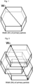
- FIG. 1 is a schematic diagram for explaining the width (Wi) of a primary particle that is used in the present invention.
- the width Wi of the primary particle is defined as shown in FIG. 1 . That is to say, assuming that the primary particle has a hexagonal plate-shaped surface, the major diameter of the particle is the "width Wi of the primary particle".
- a secondary particle is a particle that is an aggregate formed of a collection of a plurality of primary particles.
- FIG. 2 is a schematic diagram for explaining a secondary particle that is used in the present invention and the width (W 2 ) of the secondary particle.
- the width W 2 of the secondary particle is defined as shown in FIG. 2 . That is to say, assuming that the secondary particle is enclosed in a sphere, the diameter of the sphere is the "width W 2 of the secondary particle".
- the average width of primary particles as measured using a SEM method is between 5 nm and 200 nm inclusive, preferably between 5 nm and 150 nm inclusive, more preferably between 5 nm and 100 nm inclusive, even more preferably between 5 nm and 80 nm inclusive, yet more preferably between 5 nm and 60 nm inclusive, and most preferably between 5 nm and 50 nm inclusive.
- the average width of primary particles is obtained from an arithmetic mean of measured values of the width of any 100 crystals in a SEM micrograph, using the SEM method. In principle, the width of primary particles cannot be measured using a laser diffraction method. Therefore, the width of primary particles is visually observed using the SEM method.
- the degree of monodispersity expressed by the equation below is 50% or greater, and preferably 80% or greater.
- the width of secondary particles is measured using a dynamic light scattering method, because it is difficult to accurately measure the width of secondary particles using a SEM method.
- Degree of monodispersity (%) (average width of primary particles as measured using SEM method/average width of secondary particles as measured using dynamic light scattering method) ⁇ 100
- the BET specific surface area is 20 to 600 m 2 /g, preferably 30 to 500 m 2 /g, and more preferably 40 to 400 m 2 /g. If the BET specific surface area is less than 20 m 2 /g, dispersion of primary particles in a powder state is insufficient. If the BET specific surface area is more than 600 m 2 /g, the powder is bulky, and therefore the ease of handling when, for example, kneading the hydrotalcite together with a synthetic resin is poor.
- a surface treatment agent include, but are not limited to, an anionic surfactant, a cationic surfactant, a phosphate ester treatment agent, a silane coupling agent, a titanate coupling agent, an aluminum coupling agent, a silicone-based treatment agent, silicic acid, water glass, and the like.
- the surface treatment agent is particularly preferably at least one selected from the group consisting of oleic acid, stearic acid, octanoic acid, and octylic acid.
- the amount of surface treatment agent is 0.01 to 20 wt%, and preferably 0.1 to 15 wt%, with respect to the weight of the hydrotalcite.
- a resin composition of the present invention contains the hydrotalcite of the present invention in an amount of 0.1 to 250 parts by weight with respect to 100 parts by weight of a resin.
- the amount of the hydrotalcite that is added is more preferably 1 to 200 parts by weight with respect to 100 parts by weight of the resin.
- the method for mixing and kneading the resin and the hydrotalcite of the present invention is no particular limitation on the method for mixing and kneading the resin and the hydrotalcite of the present invention, but a method that enables uniform mixing of the two components is preferable.
- the mixing and kneading are performed using a single- or twin-screw extruder, a roller, a Banbury mixer, or the like.
- the molding method and a known molding means can be employed as desired, depending on the types of resin and rubber, the type of the desired molded product, and the like.
- injection molding, extrusion molding, blow molding, press molding, rotational molding, calender molding, sheet forming molding, transfer molding, laminate molding, vacuum forming, and the like can be employed.
- the resin that is used in the present invention means a resin and/or a rubber, and examples thereof include halogen-containing resins such as polyvinyl chloride, polyvinyl bromide, polyvinyl fluoride, polyvinylidene chloride, chlorinated polyethylene, chlorinated polypropylene, brominated polyethylene, chlorinated rubber, a vinyl chloride-vinyl acetate copolymer, a vinyl chloride-ethylene copolymer, a vinyl chloride-propylene copolymer, a vinyl chloride-styrene copolymer, a vinyl chloride-isobutylene copolymer, a vinyl chloride-vinylidene chloride copolymer, a vinyl chloride-styrene-acrylonitrile copolymer, a vinyl chloride-butadiene copolymer, a vinyl chloride-chlorinated propylene copolymer, a vinyl chloride-vinylidene chloride-vinyl
- the examples of the resin include thermoplastic resins such as polyethylene, a copolymer of ethylene and another ⁇ -olefin, a copolymer of ethylene and vinyl acetate, a copolymer of ethylene and an acrylic acid ether, a copolymer of ethylene and methyl acrylate, polypropylene, a copolymer of propylene and another ⁇ -olefin, polybutene-1, poly 4-methylpentene-1, polystyrene, a copolymer of styrene and acrylonitrile, a copolymer of ethylene and a propylene diene rubber, a copolymer of ethylene and butadiene, polyvinyl acetate, polylactic acid, polyvinyl alcohol, polyacrylate, polymethacrylate, polyurethane, polyester, polyether, polyamide, ABS, polycarbonate, polyphenylene sulfide, and the like.
- thermoplastic resins such as polyethylene,
- the examples of the resin include thermosetting resins such as a phenolic resin, a melamine resin, an epoxy resin, an unsaturated polyester resin, an alkyd resin, and the like.
- thermosetting resins such as a phenolic resin, a melamine resin, an epoxy resin, an unsaturated polyester resin, an alkyd resin, and the like.
- the examples of the resin include EPDM, SBR, NBR, butyl rubber, chloroprene rubber, isoprene rubber, chlorosulfonated polyethylene rubber, silicone rubber, fluororubber, chlorinated butyl rubber, brominated butyl rubber, epichlorohydrin rubber, and the like.
- additives for example, an antioxidant, a reinforcing agent such as talc, an ultraviolet absorber, a lubricant, a flatting agent such as microparticulate silica, a pigment such as carbon black, a flame retardant such as a bromine-based flame retardant or a phosphate ester-based flame retardant, and the like can be appropriately selected and added to the resin composition of the present invention.
- a flame-retarding assistant such as zinc stannate, alkali metal stannate, or a carbon powder, and a filling agent such as calcium carbonate can be appropriately selected and added.
- additives are 0.01 to 5 parts by weight for an antioxidant, 0.1 to 50 parts by weight for a reinforcing agent, 0.01 to 5 parts by weight for an ultraviolet absorber, 0.1 to 5 parts by weight for a lubricant, 0.01 to 5 parts by weight for a flatting agent, 0.01 to 5 parts by weight for a pigment, 0.1 to 50 parts by weight for a flame retardant, 0.01 to 10 parts by weight for a flame-retarding assistant, and 1 to 50 parts by weight for a filling agent.
- the solvent is water and/or an organic solvent
- the concentration of the hydrotalcite is 0.1 to 300 g/L.
- the concentration of the hydrotalcite is preferably 0.5 to 250 g/L, and more preferably 1 to 200 g/L.
- a method for producing a hydrotalcite of the present invention includes the following four steps.
- Raw materials for the hydrotalcite of the present invention are a salt of a divalent metal, a salt of a trivalent metal, a monovalent organic acid and/or organic acid salt that forms a complex with the trivalent metal, and an alkali metal hydroxide salt.
- the divalent metal salt include, but are not limited to, water-soluble divalent metal salts, such as magnesium chloride, magnesium bromide, magnesium nitrate, magnesium acetate, zinc chloride, zinc bromide, zinc nitrate, zinc acetate, and the like.
- a divalent metal salt containing a monovalent anion is used.
- a combination of two or more divalent metal salts can also be used.
- magnesium chloride and/or zinc chloride is used.
- the trivalent metal salt include, but are not limited to, water-soluble trivalent metal salts, such as aluminum chloride, aluminum bromide, aluminum nitrate, and aluminum acetate.
- a trivalent metal salt containing a monovalent anion is used.
- a combination of two or more trivalent metal salts can also be used.
- aluminum chloride is used.
- the precipitation pH of a trivalent metal ion as a hydroxide is lower than the precipitation pH of a divalent metal. For this reason, even if the pH during the reaction is kept constant by using a pH regulator, the trivalent ion is precipitated as a hydroxide first.
- the difference in precipitation pH between the divalent metal and the trivalent metal causes crystal strain, which results in aggregation of hydrotalcite primary particles.
- the precipitation pH of the trivalent metal ion as a hydroxide is increased to a value closer to the precipitation pH of the divalent metal by using the monovalent organic acid and/or organic acid salt as a complexing agent and causing the complexing agent and the trivalent metal to form a complex together, and thus, a hydrotalcite with less crystal strain can be obtained. Due to the steric hindrance effect of molecules of the complexing agent, the complexing agent also has an effect of suppressing crystal growth of primary particles of the hydrotalcite.
- Examples of the monovalent organic acid and/or organic acid salt that form a complex with the trivalent metal include, but are not limited to, lactic acid, sodium lactate, formic acid, sodium formate, acetic acid, sodium acetate, propionic acid, and sodium propionate.
- a combination of two or more organic acids and organic acid salts can also be used.
- lactic acid, sodium lactate, acetic acid, and sodium acetate are used.
- alkali metal hydroxide salt include, but are not limited to, sodium hydroxide and potassium hydroxide.
- the divalent metal salt, the trivalent metal salt, and the monovalent organic acid and/or organic acid salt that forms a complex with the trivalent metal are dissolved in an aqueous solvent to prepare an aqueous solution of a water-soluble composite metal salt.
- the concentration of the divalent metal in the aqueous solution of the water-soluble composite metal salt is 0.01 to 2 mol/L, and preferably 0.1 to 1.5 mol/L.
- the concentration of the trivalent metal is 0.01 to 2 mol/L, and preferably 0.1 to 1.5 mol/L.
- the concentration of the alkali metal hydroxide is 0.01 to 4 mol/L, and preferably 0.1 to 2 mol/L.
- the ratio of the divalent metal to the trivalent metal is 1.78 ⁇ M 2+ /M 3+ ⁇ 4.88, and preferably 1.94 ⁇ M 2+ /M 3+ ⁇ 4.26.
- the amount added of the monovalent organic acid and/or organic acid salt that forms a complex with the trivalent metal is 0.1 to 2.2 eq., and more preferably 0.3 to 2 eq., with respect to the trivalent metal.
- An amount of less than 0.1 eq. causes primary particles of the hydrotalcite to be 200 nm or larger and therefore is not preferable.
- An amount of more than 2.2 eq. causes a negative ion derived from the complexing agent to be present between the layers of the hydrotalcite, resulting in gelation of the suspension due to a swelling effect, and therefore is not preferable.
- the hydrotalcite of the present invention can be prepared through a continuous reaction. Compared with a batch reaction, the ion concentration and the pH in the solution can be kept uniform. Therefore, a hydrotalcite with less lattice strain can be produced, and the production efficiency is better than that of a batch reaction.
- the concentration in terms of the hydrotalcite is 0.1 to 300 g/L, preferably 0.5 to 250 g/L, and more preferably 1 to 200 g/L.
- a concentration of less than 0.1 g/L leads to low productivity and therefore is not preferable, and a concentration of more than 300 g/L causes aggregation of primary particles and therefore is not preferable.
- the temperature is 0 to 60°C, preferably 10 to 50°C, and more preferably 20 to 40°C.
- a temperature of less than 0°C causes the suspension to freeze and therefore is not preferable, and a temperature of more than 60°C causes primary particles to be 200 nm or larger and therefore is not preferable.
- the pH is 8.5 to 11.5, preferably 8.8 to 11.0, and more preferably 9.1 to 10.5.
- a pH of less than 8.5 causes the lattice strain in the hydrotalcite to increase and the degree of monodispersity to decrease and therefore is not preferable
- a pH of more than 11.5 causes primary particles of the hydrotalcite after aging to be 200 nm or larger and therefore is not preferable.
- the suspension containing the hydrotalcite prepared in the reaction step is dehydrated, then washing with an amount of deionized water that is 20 to 30 times the hydrotalcite in weight is performed, and resuspending in water and/or an organic solvent is performed. By performing this step, salts such as sodium can be removed, and thus, aggregation of primary particles during the aging step can be prevented.
- the washing step ion exchange with any anion can be performed after dehydration and prior to washing with water.
- the first method is a method in which, after the suspension containing the post-reaction hydrotalcite is dehydrated to obtain a cake, the cake is dispersed in water and/or alcohol, and an anion-containing aqueous solution is added thereto, followed by stirring and retaining.
- the equivalent of the anion is 1 to 5 eq, and more preferably 1.5 to 3 eq, with respect to the hydrotalcite.
- the stirring and retaining temperature is preferably 30 to 90°C, and more preferably 50 to 80°C.
- the concentration of the hydrotalcite in terms of the hydrotalcite is preferably 0.1 to 300 g/L, more preferably 0.5 to 250 g/L, and even more preferably 1 to 200 g/L.
- the second ion exchange method is a method in which, after the suspension containing the post-reaction hydrotalcite is dehydrated to obtain a cake, an anion-containing aqueous solution is directly added to the cake. At this time, the amount of the anion that is added is 1 to 5 eq, and preferably 1.5 to 3 eq, with respect to the hydrotalcite.
- the suspension containing the hydrotalcite prepared in the washing step is stirred and retained at 0 to 100°C for 1 to 60 hours.
- aggregation of primary particles can be alleviated, and a suspension in which primary particles are sufficiently dispersed can be obtained.
- An aging time of less than 1 hour is an insufficient length of time to alleviate the aggregation of primary particles. Even when aging is performed longer than 60 hours, the aggregation state remains unchanged, and therefore this is meaningless.
- the aging time is preferably 2 to 30 hours, and more preferably 4 to 24 hours.
- An aging temperature of more than 100°C causes primary particles to be larger than 200 nm and therefore is not preferable.
- An aging temperature of less than 0°C causes the suspension to freeze and therefore is not preferable.
- the aging temperature is preferably 20 to 90°C, and more preferably 40 to 80°C.
- the concentration in terms of the hydrotalcite is 0.1 to 300 g/L, more preferably 0.5 to 250 g/L, and even more preferably 1 to 200 g/L.
- a concentration of less than 0.1 g/L leads to low productivity and therefore is not preferable, and a concentration of more than 300 g/L causes aggregation of primary particles and therefore is not preferable
- the hydrotalcite particles are surface-treated, and thus, aggregation of primary particles in the suspension, and in a resin when added, kneaded, or dispersed in the resin, can be prevented.
- a wet method or a dry method can be used for the surface treatment. When uniformity of the treatment is taken into account, a wet method is favorably used.
- the temperature of the suspension after the aging step is adjusted, and a dissolved surface treatment agent is added thereto under stirring. During the surface treatment, the temperature is appropriately adjusted to a temperature at which the surface treatment agent dissolves.
- At least one selected from an anionic surfactant, a cationic surfactant, a phosphate ester-based treatment agent, a silane coupling agent, a titanate coupling agent, an aluminum coupling agent, a silicone-based treatment agent, sodium silicate, and the like can be used as the surface treatment agent.
- the surface treatment agent is particularly preferably at least one selected from the group consisting of oleic acid, stearic acid, octanoic acid, and octylic acid.
- the amount of the surface treatment agent is preferably 0.01 to 20 wt%, and more preferably 0.1 to 15 wt%, with respect to the weight of the hydrotalcite.
- the suspension is dehydrated, followed by washing with an amount of deionized water that is 20 to 30 times the solid content in weight.
- the hydrotalcite after the washing with water is suspended in water and/or an organic solvent.
- concentration of the hydrotalcite is 0.1 to 300 g/L, preferably 0.5 to 250 g/L, and more preferably 1 to 200 g/L.
- organic solvent examples include, but are not limited to, benzene, toluene, xylene, normal hexane, isohexane, normal heptane, cyclohexane, methylcyclohexane, ethylcyclohexane, methanol, ethanol, normal propyl alcohol, isopropyl alcohol, normal butanol, isobutanol, octanol, monoethylene glycol, diethylene glycol, triethylene glycol, propylene glycol, ethyl acetate, butyl acetate, isobutyl acetate, amyl acetate, methyl acetate, propylene glycol monomethyl ether acetate, methyl ethyl ketone, acetone, methyl isobutyl ketone, diisobutyl ketone, cyclohexanone, isophorone, diacetone alcohol, ethylene glycol monomethyl ether,
- the hydrotalcite after the washing with water is dried to obtain a hydrotalcite of the present invention.
- hot-air drying, vacuum drying, or the like can be used as the drying method, the drying method is not limited to a specific method.
- vacuum drying is used in order to prevent aggregation of primary particles intermediated by water.
- the drying temperature is 120 to 350°C, and the retaining time is 1 to 24 hours. With this treatment, water of crystallization can be removed from the hydrotalcite, and the range of m can be set to be 0 ⁇ m ⁇ 0.05.
- the drying temperature is preferably 130 to 340°C, and more preferably 140 to 330°C.
- the drying time is preferably 1.5 to 22 hours, and more preferably 2 to 20 hours.
- An X-ray diffractometer (Empyrean manufactured by PANalytical) is used, and diffraction profiles of the (003) plane and the (006) plane are measured using, as an X-ray source, a Cu-K ⁇ ray that is generated under conditions of 45 KV and 40 mA.
- the measurement is performed under conditions at a goniometer speed of 10°/min with slit widths of 1° - 0.3 mm - 1° for the (003) plane and 2° - 0.3 mm - 2° for the (006) plane in the order of the divergence slit, the receiving slit, and the scattering slit.
- the width (B 0 ) at (1/2) of the height from the background to a diffraction peak is measured. From the relationship of the split width ( ⁇ ) between K ⁇ 1 and K ⁇ 2 against 2 ⁇ , ⁇ against 2 ⁇ of each of the (003) plane and the (006) plane is read. Next, based on the values of B 0 and ⁇ described above, B is obtained from the relationship between ( ⁇ /B 0 ) and (B/B 0 ). Subsequently, with respect to high-purity silicon (purity: 99.999%), diffraction profiles are measured with slit widths of (1/2)° - 0.3 mm - (1/2)°, and the half-width (b) is obtained.
- a sample was added to ethanol, and ultrasonic treatment was performed for 5 minutes. After that, the width of primary particles in any 100 crystals were measured using a scanning electron microscope (SEM) (JSM-7600F manufactured by JEOL Ltd.), and the arithmetic mean of the measured values was used as the average width of primary particles.
- SEM scanning electron microscope
- a sample was added to ethanol, and ultrasonic treatment was performed for 5 minutes. After that, the particle size distribution was measured using a particle size measuring apparatus based on a dynamic light scattering method (ELSZ-2 manufactured by Otsuka Electronics Co., Ltd.), and the number average diameter was used as the average width of secondary particles.
- ELSZ-2 dynamic light scattering method manufactured by Otsuka Electronics Co., Ltd.
- the specific surface area of a sample after drying was measured based on a gas adsorption method, using a specific surface area measuring apparatus (NOVA 2000 manufactured by Yuasa Ionics Co., Ltd.).
- a sample was heated and dissolved in nitric acid. After that, the amounts of Mg, Zn, and Al were determined through chelatometric titration, and the amount of Cl was determined through Volhard titration.
- the amount of CO 3 was determined based on JIS. R. 9101, using an AGK type CO 2 simple precision quantitative analysis apparatus. The amount of interlayer water was calculated from a reduction in weight using TG-DTA.
- the oleic acid or stearic acid treatment amount of a sample was determined using an ether extraction method.
- a sample was added to a polyvinyl chloride resin in the following blending ratio, and thermal stability was evaluated.
- the above-described blend was kneaded at 170°C for 5 minutes using an 8-inch roller to prepare a test roll sheet having a thickness of 0.7 mm.
- a test piece that was 4 cm in length and width was taken from the obtained roll sheet, placed on a stainless steel plate, and subjected to a thermal stability test in a Geer oven at a degree of opening of 60% and 190°C.
- the thermal stability was evaluated based on the time (minutes) that had elapsed before the test piece was blackened or a black spot occurred thereon. The longer it took for a black spot to occur, the better the thermal stability.
- the roll sheet prepared in (h) was cut into pieces that were 4 cm in length and width. Three of the cut pieces were laid one on top of another, placed in a frame having a thickness of 2 mm, held between upper and lower stainless steel plates, and pressed in a press machine at 200°C for 10 minutes at 100 MPa. Thus, a test piece was prepared.
- the haze (degree of cloudiness) in the prepared test piece was measured based on JIS. K. 7136 by using a haze meter (automatic haze meter TC-H3DP manufactured by Tokyo Denshoku Co., Ltd.), and the transparency was evaluated. The lower the haze, the better the transparency.
- a hydrotalcite after being surface-treated and washed with water was added to 1 L of isopropyl alcohol in an amount of 10 g in terms of the solid content, and then stirred using a homogenizer at 6,000 rpm for 20 minutes, and thus, a suspension was prepared.
- the suspension was transferred to a 1-L settling tube and allowed to stand for 10 days in this state. Sampling was performed immediately after, and one day and 10 days after the suspension was prepared, and the average width of secondary particles and the sedimentation state in each of the samples were evaluated.
- the particle size distribution thereof was measured using a particle size measuring apparatus based on a dynamic light scattering method (ELSZ-2 manufactured by Otsuka Electronics Co., Ltd.), and the number average diameter was used as the average width of secondary particles. Also, the sedimentation state after one day and 10 days was visually checked, and a case where a water layer and a particle-containing layer were completely separated was evaluated as poor, whereas a case where the separation of layers was not confirmed was evaluated as good.
- ELSZ-2 dynamic light scattering method manufactured by Otsuka Electronics Co., Ltd.
- Magnesium chloride hexahydrate (Wako Pure Chemical Industries, Ltd.) and aluminum chloride hexahydrate (Wako Pure Chemical Industries, Ltd.) were dissolved in deionized water to obtain an aqueous solution containing magnesium in a concentration of 0.2 mol/L and aluminum in a concentration of 0.1 mol/L.
- sodium lactate Koreana Chemical Co., Ltd.
- sodium hydroxide was dissolved in deionized water in a concentration of 0.8 mol/L to obtain an aqueous solution of an alkali metal hydroxide.
- the aqueous solution of the water-soluble composite metal salt and the aqueous solution of the alkali metal hydroxide were dispensed, at respective flow rates of 120 mL/min and 95 mL/min, into a cylindrical reaction vessel having an overflow capacity of 215 mL, and a reaction was conducted in a continuous manner.
- the suspension that overflowed from the reaction vessel was collected, and the flow rate of the aqueous solution of the alkali metal hydroxide was adjusted so that the pH was 9.3 to 9.6.
- the temperatures of the raw materials and the reaction vessel were adjusted so that the reaction temperature was 25°C.
- stirring was performed using a screw propeller having a diameter of 2.5 cm at a rotation speed of 1,000 rpm.
- the suspension was dehydrated through suction filtering by using a circular Nutsche and a suction filtration bottle to obtain a cake.
- an aqueous solution of sodium carbonate was dispensed onto the cake in an amount of 1.5 eq. with respect to aluminum of the hydrotalcite contained in the cake, and ion exchange was performed.
- the cake after the ion exchange was washed with an amount of deionized water that was 30 times the hydrotalcite in mass in order to remove by-products, such as salts, and impurities, such as residual sodium carbonate.
- the cake after the washing with water was resuspended in deionized water.
- the cake was resuspended using a homomixer at a rotation rate of 4,000 rpm for 20 minutes.
- Deionized water was dispensed into the resuspended suspension to adjust the concentration to 50 g/L. After the concentration was adjusted, the suspension was kept at 60°C in a constant temperature bath and subjected to aging treatment for 24 hours.
- a 1 mol/L aqueous solution of sodium hydroxide (manufactured by Wako Pure Chemical Industries, Ltd.) was added to oleic acid (manufactured by Wako Pure Chemical Industries, Ltd.) in an amount of 1 eq. with respect to the oleic acid to obtain an aqueous solution of sodium oleate.
- the concentration of the aqueous solution of sodium oleate was adjusted using deionized water so that the oleic acid concentration was 5 g/L.
- the concentration of the suspension after the aging treatment was adjusted to 10 g/L. After that, the temperature of the suspension was adjusted to 60°C using a constant temperature bath, and the aqueous solution of sodium oleate was dispensed thereto in an amount of 10 wt%. After the aqueous solution of sodium oleate was dispensed, the suspension was stirred and retained at 60°C for 30 minutes.
- the suspension was cooled to room temperature, and then dehydrated by using a circular Nutsche and a suction filtration bottle to obtain a cake.
- the cake was washed with an amount of deionized water that was 20 times the amount of reaction product in terms of the solid content.
- Table 1 shows experimental conditions of Example 1, and Table 2 shows the chemical composition, the crystal strain in the ⁇ 003> direction, the average width of primary particles, the average width of secondary particles, the degree of monodispersity, the BET specific surface area, and the surface treatment amount.
- magnesium chloride hexahydrate (Wako Pure Chemical Industries, Ltd.) and aluminum chloride hexahydrate (Wako Pure Chemical Industries, Ltd.), as well as zinc chloride (Wako Pure Chemical Industries, Ltd.) were dissolved in deionized water to obtain an aqueous solution containing magnesium in a concentration of 0.15 mol/L, zinc in a concentration of 0.05 mol/L, and aluminum in a concentration of 0.1 mol/L.
- sodium lactate Koreana Chemical Co., Ltd.
- Example 2 shows experimental conditions of Example 2, and Table 2 shows the chemical composition, the crystal strain in the ⁇ 003> direction, the average width of primary particles, the average width of secondary particles, the degree of monodispersity, the BET specific surface area, and the surface treatment amount.
- Example 3 A sample was prepared in a manner similar to that of Example 1, except that in the raw material preparation step, the concentrations of the raw materials were adjusted so that the concentration of magnesium was 0.3 mol/L, and the concentration of aluminum was 0.1 mol/L. Thus, a sample 3 was obtained.
- Table 1 shows experimental conditions of Example 3, and Table 2 shows the chemical composition, the crystal strain in the ⁇ 003> direction, the average width of primary particles, the average width of secondary particles, the degree of monodispersity, the BET specific surface area, and the surface treatment amount.
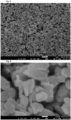
- a sample was prepared in a manner similar to that of Example 1, except that in the raw material preparation step, the concentrations of the raw materials were adjusted so that the concentration of magnesium was 1 mol/L, the concentration of aluminum was 0.5 mol/L, and the concentration of sodium hydroxide was 4.0 mol/L.
- Table 1 shows experimental conditions of Example 4, and Table 2 shows the chemical composition, the crystal strain in the ⁇ 003> direction, the average width of primary particles, the average width of secondary particles, the degree of monodispersity, the BET specific surface area, and the surface treatment amount.
- FIG. 3 shows a SEM micrograph at a magnification of 10,000 of the sample 4
- FIG. 4 shows a SEM micrograph at a magnification of 100,000 thereof.
- Example 5 A sample was prepared in a manner similar to that of Example 1, except that in the raw material preparation step, sodium lactate (manufactured by Kishida Chemical Co., Ltd.) was added in an amount of 0.5 eq. with respect to aluminum. Thus, a sample 5 was obtained.
- Table 1 shows experimental conditions of Example 5, and Table 2 shows the chemical composition, the crystal strain in the ⁇ 003> direction, the average width of primary particles, the average width of secondary particles, the degree of monodispersity, the BET specific surface area, and the surface treatment amount.
- Example 6 A sample was prepared in a manner similar to that of Example 1, except that in the reaction step, the flow rate of the aqueous solution of the alkali metal hydroxide was adjusted so that the reaction pH was 10.5 to 10.8. Thus, a sample 6 was obtained.
- Table 1 shows experimental conditions of Example 6, and Table 2 shows the chemical composition, the crystal strain in the ⁇ 003> direction, the average width of primary particles, the average width of secondary particles, the degree of monodispersity, the BET specific surface area, and the surface treatment amount.
- Example 7 A sample was prepared in a manner similar to that of Example 1, except that in the aging step, the aging temperature was set to be 90°C. Thus, a sample 7 was obtained.
- Table 1 shows experimental conditions of Example 7, and Table 2 shows the chemical composition, the crystal strain in the ⁇ 003> direction, the average width of primary particles, the average width of secondary particles, the degree of monodispersity, the BET specific surface area, and the surface treatment amount.
- Example 8 A sample was prepared in a manner similar to that of Example 1, except that in the reaction step, the reaction temperature was set to be 45°C. Thus, a sample 8 was obtained.
- Table 1 shows experimental conditions of Example 8, and Table 2 shows the chemical composition, the crystal strain in the ⁇ 003> direction, the average width of primary particles, the average width of secondary particles, the degree of monodispersity, the BET specific surface area, and the surface treatment amount.
- Example 9 A sample was prepared in a manner similar to that of Example 1, except that in the reaction step, the reaction temperature was set to be 45°C, and in the aging step, the aging temperature was set to be 90°C. Thus, a sample 9 was obtained.
- Table 1 shows experimental conditions of Example 9, and Table 2 shows the chemical composition, the crystal strain in the ⁇ 003> direction, the average width of primary particles, the average width of secondary particles, the degree of monodispersity, the BET specific surface area, and the surface treatment amount.
- Example 10 A sample was prepared in a manner similar to that of Example 1, except that in the washing step, an aqueous solution of sodium perchlorate was dispensed onto the cake in an amount of 1.5 eq. with respect to aluminum of the hydrotalcite contained in the cake, and ion exchange was performed. Thus, a sample 10 was obtained.
- Table 1 shows experimental conditions of Example 10, and Table 2 shows the chemical composition, the crystal strain in the ⁇ 003> direction, the average width of primary particles, the average width of secondary particles, the degree of monodispersity, the BET specific surface area, and the surface treatment amount.
- Example 11 A sample was prepared in a manner similar to that of Example 1, except that in the aging step, the aging time was set to be 1.5 hours. Thus, a sample 11 was obtained.
- Table 1 shows experimental conditions of Example 11, and Table 2 shows the chemical composition, the crystal strain in the ⁇ 003> direction, the average width of primary particles, the average width of secondary particles, the degree of monodispersity, the BET specific surface area, and the surface treatment amount.
- Example 1 In the surface treatment step of Example 1, while the temperature was adjusted to 80°C, a 1 mol/L aqueous solution of sodium hydroxide (manufactured by Wako Pure Chemical Industries, Ltd.) was added to stearic acid (manufactured by Wako Pure Chemical Industries, Ltd.) in an amount of 1 eq. with respect to the stearic acid to obtain an aqueous solution of sodium stearate.
- the concentration of the aqueous solution of sodium stearate was adjusted by using deionized water whose temperature was adjusted to 80°C so that the stearic acid concentration was 5 g/L.
- the concentration of the suspension after the aging treatment was adjusted to 10 g/L. After that, the temperature of the suspension was adjusted to 80°C using a constant temperature bath.
- the aqueous solution of sodium stearate was dispensed into the suspension in an amount, in terms of stearic acid, of 10 wt% with respect to the hydrotalcite at a flow rate of 3 mL/L under stirring with use of a JET AJITER. After the aqueous solution of sodium stearate was added, the suspension was stirred and retained at 80°C for 30 minutes. The other steps were performed in a similar manner, and thus, a sample 12 was obtained.
- Table 1 shows experimental conditions of Example 12, and Table 2 shows the chemical composition, the crystal strain in the ⁇ 003> direction, the average width of primary particles, the average width of secondary particles, the degree of monodispersity, the BET specific surface area, and the surface treatment amount.
- Example 1 The sample 1 of Example 1 was placed in a hot-air dryer and dried at 200°C for 12 hours to obtain a sample 13.
- Table 1 shows experimental conditions of Example 13
- Table 2 shows the chemical composition, the crystal strain in the ⁇ 003> direction, the average width of primary particles, the average width of secondary particles, the degree of monodispersity, the BET specific surface area, and the surface treatment amount.
- Example 14 A sample was prepared in a manner similar to that of Example 1, except that in the raw material preparation step, sodium lactate was not added. Thus, a sample 14 was obtained.
- Table 1 shows experimental conditions of Comparative Example 1, and Table 2 shows the chemical composition, the crystal strain in the ⁇ 003> direction, the average width of primary particles, the average width of secondary particles, the degree of monodispersity, the BET specific surface area, and the surface treatment amount.
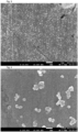
- Example 1 A sample was prepared in a manner similar to that of Example 1, except that in the reaction step, the reaction temperature was set to be 75°C. Thus, a sample 15 was obtained.
- Table 1 shows experimental conditions of Comparative Example 2, and Table 2 shows the chemical composition, the crystal strain in the ⁇ 003> direction, the average width of primary particles, the average width of secondary particles, the degree of monodispersity, the BET specific surface area, and the surface treatment amount.
- FIG. 5 shows a SEM micrograph at a magnification of 10,000 of the sample 15, and
- FIG. 6 shows a SEM micrograph at a magnification of 100,000 thereof.
- Example 16 A sample was prepared in a manner similar to that of Example 1, except that in the reaction step, the reaction pH was set to be 8.0 to 8.3. Thus, a sample 16 was obtained.
- Table 1 shows experimental conditions of Comparative Example 3, and Table 2 shows the chemical composition, the crystal strain in the ⁇ 003> direction, the average width of primary particles, the average width of secondary particles, the degree of monodispersity, the BET specific surface area, and the surface treatment amount.
- Example 17 A sample was prepared in a manner similar to that of Example 1, except that in the reaction step, the reaction pH was set to be 11.7 to 12.0. Thus, a sample 17 was obtained.
- Table 1 shows experimental conditions of Comparative Example 4, and Table 2 shows the chemical composition, the crystal strain in the ⁇ 003> direction, the average width of primary particles, the average width of secondary particles, the degree of monodispersity, the BET specific surface area, and the surface treatment amount.
- Example 1 A sample was prepared in a manner similar to that of Example 1, except that in the aging step, aging was performed at 120°C for 24 hours using an autoclave. Thus, a sample 18 was obtained.
- Table 1 shows experimental conditions of Comparative Example 5, and Table 2 shows the chemical composition, the crystal strain in the ⁇ 003> direction, the average width of primary particles, the average width of secondary particles, the degree of monodispersity, the BET specific surface area, and the surface treatment amount.
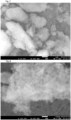
- Example 1 shows experimental conditions of Comparative Example 6, and Table 2 shows the chemical composition, the crystal strain in the ⁇ 003> direction, the average width of primary particles, the average width of secondary particles, the degree of monodispersity, the BET specific surface area, and the surface treatment amount.
- FIG. 7 shows a SEM micrograph at a magnification of 10,000 of the sample 19
- FIG. 8 shows a SEM micrograph at a magnification of 100,000 thereof.
- Example 1 The sample 1 obtained in Example 1 was added to a polyvinyl chloride resin in the following blending ratio, and thermal stability and transparency were evaluated.
- the above-described blend was kneaded at 170°C for 5 minutes using an 8-inch roller to prepare a test roll sheet having a thickness of 0.7 mm.
- a test piece that was 4 cm in length and width was taken from the obtained roll sheet, placed on a stainless steel plate, and subjected to a thermal stability test in a Geer oven at a degree of opening of 60% and 190°C. The thermal stability was evaluated based on the time (minutes) that had elapsed before the test piece was blackened or a black spot occurred thereon.
- the above-described roll sheet was cut into pieces that were 4 cm in length and width. Three of the cut pieces were laid one on top of another, placed in a frame having a thickness of 2 mm, held between upper and lower stainless steel plates, and pressed in a press machine at 200°C for 10 minutes at 100 MPa. Thus, a test piece was prepared. The degree of cloudiness (haze) in the prepared test piece was measured based on JIS. K. 7136 by using a haze meter, and the transparency was evaluated. Table 3 shows the components of the blend, the result of the thermal stability test, and the result of the transparency test of Example 14.
- Example 2 The sample 2 obtained in Example 2 was added to a polyvinyl chloride resin in a blending ratio similar to that of Example 14, and thermal stability and transparency were evaluated.
- Table 3 shows the components of the blend, the result of the thermal stability test, and the result of the transparency test of Example 15.
- Example 3 The sample 3 obtained in Example 3 was added to a polyvinyl chloride resin in a blending ratio similar to that of Example 14, and thermal stability and transparency were evaluated. Table 3 shows the components of the blend, the result of the thermal stability test, and the result of the transparency test of Example 16.
- Example 4 The sample 4 obtained in Example 4 was added to a polyvinyl chloride resin in a blending ratio similar to that of Example 14, and thermal stability and transparency were evaluated. Table 3 shows the components of the blend, the result of the thermal stability test, and the result of the transparency test of Example 17.
- Example 5 The sample 5 obtained in Example 5 was added to a polyvinyl chloride resin in a blending ratio similar to that of Example 14, and thermal stability and transparency were evaluated. Table 3 shows the components of the blend, the result of the thermal stability test, and the result of the transparency test of Example 18.
- Example 6 The sample 6 obtained in Example 6 was added to a polyvinyl chloride resin in a blending ratio similar to that of Example 14, and thermal stability and transparency were evaluated. Table 3 shows the components of the blend, the result of the thermal stability test, and the result of the transparency test of Example 19.
- Example 7 The sample 7 obtained in Example 7 was added to a polyvinyl chloride resin in a blending ratio similar to that of Example 14, and thermal stability and transparency were evaluated. Table 3 shows the components of the blend, the result of the thermal stability test, and the result of the transparency test of Example 20.
- Example 8 The sample 8 obtained in Example 8 was added to a polyvinyl chloride resin in a blending ratio similar to that of Example 14, and thermal stability and transparency were evaluated. Table 3 shows the components of the blend, the result of the thermal stability test, and the result of the transparency test of Example 21.
- Example 9 The sample 9 obtained in Example 9 was added to a polyvinyl chloride resin in a blending ratio similar to that of Example 14, and thermal stability and transparency were evaluated. Table 3 shows the components of the blend, the result of the thermal stability test, and the result of the transparency test of Example 22.
- Example 10 The sample 10 obtained in Example 10 was added to a polyvinyl chloride resin in a blending ratio similar to that of Example 14 , and thermal stability and transparency were evaluated. Table 3 shows the components of the blend, the result of the thermal stability test, and the result of the transparency test of Example 23.
- Example 11 The sample 11 obtained in Example 11 was added to a polyvinyl chloride resin in a blending ratio similar to that of Example 14, and thermal stability and transparency were evaluated. Table 3 shows the components of the blend, the result of the thermal stability test, and the result of the transparency test of Example 24.
- Example 12 The sample 12 obtained in Example 12 was added to a polyvinyl chloride resin in a blending ratio similar to that of Example 14, and thermal stability and transparency were evaluated. Table 3 shows the components of the blend, the result of the thermal stability test, and the result of the transparency test of Example 25.
- Example 13 The sample 13 obtained in Example 13 was added to a polyvinyl chloride resin in a blending ratio similar to that of Example 14, and thermal stability and transparency were evaluated. Table 3 shows the components of the blend, the result of the thermal stability test, and the result of the transparency test of Example 26.
- Comparative Example 1 The sample 14 obtained in Comparative Example 1 was added to a polyvinyl chloride resin in a blending ratio similar to that of Example 14, and thermal stability and transparency were evaluated. Table 3 shows the components of the blend, the result of the thermal stability test, and the result of the transparency test of Comparative Example 7.
- Example 15 The sample 15 obtained in Comparative Example 2 was added to a polyvinyl chloride resin in a blending ratio similar to that of Example 14, and thermal stability and transparency were evaluated.
- Table 3 shows the components of the blend, the result of the thermal stability test, and the result of the transparency test of Comparative Example 8.
- Example 3 The sample 16 obtained in Comparative Example 3 was added to a polyvinyl chloride resin in a blending ratio similar to that of Example 14, and thermal stability and transparency were evaluated. Table 3 shows the components of the blend, the result of the thermal stability test, and the result of the transparency test of Comparative Example 9.
- Comparative Example 4 The sample 17 obtained in Comparative Example 4 was added to a polyvinyl chloride resin in a blending ratio similar to that of Example 14, and thermal stability and transparency were evaluated. Table 3 shows the components of the blend, the result of the thermal stability test, and the result of the transparency test of Comparative Example 10.
- Comparative Example 5 The sample 18 obtained in Comparative Example 5 was added to a polyvinyl chloride resin in a blending ratio similar to that of Example 14, and thermal stability and transparency were evaluated. Table 3 shows the components of the blend, the result of the thermal stability test, and the result of the transparency test of Comparative Example 11.
- the hydrotalcite that was washed with water after the surface treatment in Example 1 was collected in an amount of 10 g in terms of the solid content, and added to 1 L of isopropyl alcohol. After that, stirring was performed using a homogenizer at 6,000 rpm for 20 minutes to prepare a suspension. The suspension was transferred to a 1-L settling tube and allowed to stand for 10 days in this state. Sampling was performed immediately after, and one day and 10 days after the suspension was prepared, and the average width of secondary particles and the sedimentation state were evaluated. Table 4 shows the evaluation results.
- Example 2 The hydrotalcite that was washed with water after the surface treatment in Example 2 was treated in a manner similar to that of Example 27 to prepare a suspension. Sampling was performed immediately after, and one day and 10 days after the suspension was prepared, and the average width of secondary particles and the sedimentation state were evaluated. Table 4 shows the evaluation results.
- Example 3 The hydrotalcite that was washed with water after the surface treatment in Example 3 was treated in a manner similar to that of Example 27 to prepare a suspension. Sampling was performed immediately after, and one day and 10 days after the suspension was prepared, and the average width of secondary particles and the sedimentation state were evaluated. Table 4 shows the evaluation results.
- Example 4 The hydrotalcite that was washed with water after the surface treatment in Example 4 was treated in a manner similar to that of Example 27 to prepare a suspension. Sampling was performed immediately after, and one day and 10 days after the suspension was prepared, and the average width of secondary particles and the sedimentation state were evaluated. Table 4 shows the evaluation results.
- Example 5 The hydrotalcite that was washed with water after the surface treatment in Example 5 was treated in a manner similar to that of Example 27 to prepare a suspension. Sampling was performed immediately after, and one day and 10 days after the suspension was prepared, and the average width of secondary particles and the sedimentation state were evaluated. Table 4 shows the evaluation results.
- Example 6 The hydrotalcite that was washed with water after the surface treatment in Example 6 was treated in a manner similar to that of Example 27 to prepare a suspension. Sampling was performed immediately after, and one day and 10 days after the suspension was prepared, and the average width of secondary particles and the sedimentation state were evaluated. Table 4 shows the evaluation results.
- Example 7 The hydrotalcite that was washed with water after the surface treatment in Example 7 was treated in a manner similar to that of Example 27 to prepare a suspension. Sampling was performed immediately after, and one day and 10 days after the suspension was prepared, and the average width of secondary particles and the sedimentation state were evaluated. Table 4 shows the evaluation results.
- Example 8 The hydrotalcite that was washed with water after the surface treatment in Example 8 was treated in a manner similar to that of Example 27 to prepare a suspension. Sampling was performed immediately after, and one day and 10 days after the suspension was prepared, and the average width of secondary particles and the sedimentation state were evaluated. Table 4 shows the evaluation results.
- Example 9 The hydrotalcite that was washed with water after the surface treatment in Example 9 was treated in a manner similar to that of Example 27 to prepare a suspension. Sampling was performed immediately after, and one day and 10 days after the suspension was prepared, and the average width of secondary particles and the sedimentation state were evaluated. Table 4 shows the evaluation results.
- Example 10 The hydrotalcite that was washed with water after the surface treatment in Example 10 was treated in a manner similar to that of Example 27 to prepare a suspension. Sampling was performed immediately after, and one day and 10 days after the suspension was prepared, and the average width of secondary particles and the sedimentation state were evaluated. Table 4 shows the evaluation results.
- Example 11 The hydrotalcite that was washed with water after the surface treatment in Example 11 was treated in a manner similar to that of Example 27 to prepare a suspension. Sampling was performed immediately after, and one day and 10 days after the suspension was prepared, and the average width of secondary particles and the sedimentation state were evaluated. Table 4 shows the evaluation results.
- Example 12 The hydrotalcite that was washed with water after the surface treatment in Example 12 was treated in a manner similar to that of Example 27 to prepare a suspension. Sampling was performed immediately after, and one day and 10 days after the suspension was prepared, and the average width of secondary particles and the sedimentation state were evaluated. Table 4 shows the evaluation results.
- Example 13 The hydrotalcite that was washed with water after the surface treatment in Example 13 was treated in a manner similar to that of Example 27 to prepare a suspension. Sampling was performed immediately after, and one day and 10 days after the suspension was prepared, and the average width of secondary particles and the sedimentation state were evaluated. Table 4 shows the evaluation results.
- the hydrotalcite that was washed with water after the surface treatment in Comparative Example 1 was treated in a manner similar to that of Example 27 to prepare a suspension. Sampling was performed immediately after, and one day and 10 days after the suspension was prepared, and the average width of secondary particles and the sedimentation state were evaluated. Table 4 shows the evaluation results.
- the hydrotalcite that was washed with water after the surface treatment in Comparative Example 2 was treated in a manner similar to that of Example 27 to prepare a suspension. Sampling was performed immediately after, and one day and 10 days after the suspension was prepared, and the average width of secondary particles and the sedimentation state were evaluated. Table 4 shows the evaluation results.
- the hydrotalcite that was washed with water after the surface treatment in Comparative Example 3 was treated in a manner similar to that of Example 27 to prepare a suspension. Sampling was performed immediately after, and one day and 10 days after the suspension was prepared, and the average width of secondary particles and the sedimentation state were evaluated. Table 4 shows the evaluation results.
- the hydrotalcite that was washed with water after the surface treatment in Comparative Example 4 was treated in a manner similar to that of Example 27 to prepare a suspension. Sampling was performed immediately after, and one day and 10 days after the suspension was prepared, and the average width of secondary particles and the sedimentation state were evaluated. Table 4 shows the evaluation results.
- the hydrotalcite that was washed with water after the surface treatment in Comparative Example 5 was treated in a manner similar to that of Example 27 to prepare a suspension. Sampling was performed immediately after, and one day and 10 days after the suspension was prepared, and the average width of secondary particles and the sedimentation state were evaluated. Table 4 shows the evaluation results.
- the hydrotalcite of the present invention can be used for various uses including a thermal stabilizer for a polyvinyl chloride resin, a neutralizing agent for a residue of a polyolefin polymerization catalyst, an acid acceptor for a halogen-containing rubber, a heat-insulating agent for an agricultural film, and the like.
- a suspension that contains the hydrotalcite can be favorably used as a liquid antacid or thermal stabilizer.
- the hydrotalcite of the present invention has a significantly improved anion-exchangeability compared with conventional hydrotalcites, and therefore exhibits superior effects as a stabilizer, a neutralizing agent, and an acid acceptor to a conventional hydrotalcite if added in the same amount, and can exhibit equivalent performance to that of a conventional hydrotalcite even if added in a smaller amount than the conventional hydrotalcite. Moreover, when the hydrotalcite of the present invention is added to a resin, higher transparency is obtained compared with when a conventional hydrotalcite is added in the same amount.
Landscapes
- Chemical & Material Sciences (AREA)
- Organic Chemistry (AREA)
- Health & Medical Sciences (AREA)
- Chemical Kinetics & Catalysis (AREA)
- Medicinal Chemistry (AREA)
- Polymers & Plastics (AREA)
- Inorganic Chemistry (AREA)
- Life Sciences & Earth Sciences (AREA)
- Geology (AREA)
- Compounds Of Alkaline-Earth Elements, Aluminum Or Rare-Earth Metals (AREA)
- Compositions Of Macromolecular Compounds (AREA)
Claims (15)
- Ein Hydrotalcit, dargestellt durch eine nachstehende Formel (1):
(M2+)1-x(M3+)x(OH)2(An)x/n·mH2O (1)
wobei M2+ mindestens ein zweiwertiges Metall angibt, M3+ mindestens ein dreiwertiges Metall angibt, An- ein n-wertiges Anion angibt, n eine ganze Zahl von 1 bis 6 angibt und x und m innerhalb jeweiliger Bereiche von 0,17 ≤ x ≤ 0,36 und 0 ≤ m ≤ 10 liegen,wobei das Hydrotalcit nachstehende (A) bis (C) erfüllt:(A) eine Gitterspannung in der <003>-Richtung, gemessen unter Verwendung eines Röntgenbeugungsverfahrens, beträgt 3 × 10⁻³ oder weniger;(B) eine mittlere Breite von Primärteilchen, gemessen unter Verwendung eines REM-Verfahrens, beträgt zwischen 5 nm und 200 nm einschließlich; und(C) ein Monodispersitätsgrad, ausgedrückt durch eine nachstehende Gleichung, beträgt 50% oder mehr:Monodispersitätsgrad (%) = (mittlere Breite von Primärteilchen, gemessen unter Verwendung des REM-Verfahrens/mittlere Breite von Sekundärteilchen, gemessen unter Verwendung eines dynamischen Lichtstreuungsverfahrens) x 100. - Das Hydrotalcit nach Anspruch 1, wobei (A) die Gitterspannung in der <003>-Richtung, gemessen unter Verwendung des Röntgenbeugungsverfahrens, 2,5 × 10⁻³ oder weniger beträgt.
- Das Hydrotalcit nach Anspruch 1, wobei (B) die mittlere Breite von Primärteilchen, gemessen unter Verwendung des REM-Verfahrens, zwischen 5 nm und 150 nm einschließlich beträgt.
- Das Hydrotalcit nach Anspruch 1, wobei (C) der Monodispersitätsgrad 80% oder mehr beträgt.
- Das Hydrotalcit nach Anspruch 1, wobei in der Formel (1) M2+ mindestens eines, ausgewählt aus der Gruppe bestehend aus Mg und Zn, ist und M3+ gleich Al ist.
- Das Hydrotalcit nach Anspruch 1, wobei in der Formel (1) der Bereich von m 0 ≤ m ≤ 0,05 beträgt.
- Das Hydrotalcit nach Anspruch 1, wobei eine BET-spezifische Oberfläche 20 bis 600 m2/g beträgt.
- Das Hydrotalcit nach Anspruch 1, wobei eine Oberfläche des Hydrotalcits mit mindestens einem, ausgewählt aus der Gruppe bestehend aus einem anionischen grenzflächenaktiven Mittel, einem kationischen grenzflächenaktiven Mittel, einem Phosphatesterbehandlungsmittel, einem Silankupplungsmittel, einem Titanatkupplungsmittel, einem Aluminiumkupplungsmittel, einem Behandlungsmittel auf Silikonbasis, Kieselsäure und Wasserglas, oberflächenbehandelt ist.
- Ein Verfahren zur Herstellung eines Hydrotalcits, wobei das Verfahren die folgenden vier Schritte umfasst:(1) einen Ausgangsmaterial-Herstellungsschritt des Herstellens einer wässrigen Lösung eines wasserlöslichen Verbundmetallsalzes und einer wässrigen Lösung eines Alkalimetallhydroxids, wobei die wässrige Lösung des wasserlöslichen Verbundmetallsalzes ein Salz eines zweiwertigen Metalls, ein Salz eines dreiwertigen Metalls und eine einwertige organische Säure, und/oder ein organisches Säuresalz, das mit dem dreiwertigen Metall einen Komplex bildet, enthält;(2) einen Reaktionsschritt des Bewirkens einer kontinuierlichen Reaktion der wässrigen Lösung des wasserlöslichen Verbundmetallsalzes und der wässrigen Lösung des Alkalimetallhydroxids, die in Schritt (1) hergestellt wurden, miteinander bei einer Reaktionstemperatur von 0 bis 60°C und einem Reaktions-pH von 8,5 bis 11,5, um dadurch eine Suspension, die ein Hydrotalcit enthält, zu erhalten;(3) einen Waschschritt des Entwässerns der in Schritt (2) erhaltenen Suspension, die das Hydrotalcit enthält, und des anschließenden Durchführens von Waschen mit Wasser und des Suspendierens in Wasser und/oder einem organischen Lösungsmittel; und(4) einen Alterungsschritt des Rührens und Haltens einer in Schritt (3) erhaltenen Suspension, die das gewaschene Hydrotalcit enthält, bei 0 bis 100°C für 1 bis 60 Stunden.
- Das Verfahren zur Herstellung eines Hydrotalcits nach Anspruch 9, wobei in dem Ausgangsmaterial-Herstellungsschritt nach Anspruch 9 die einwertige organische Säure und/oder das organische Säuresalz, das einen Komplex mit dem dreiwertigen Metall bildet, mindestens eines, ausgewählt aus der Gruppe bestehend aus Milchsäure, Natriumlactat, Essigsäure und Natriumacetat, ist.
- Ein Verfahren zur Herstellung des Hydrotalcits nach Anspruch 9, wobei das Hydrotalcit erhalten wird durch Trocknen des Hydrotalcits nach Anspruch 1 bei 100°C bis 350°C für 1 bis 24 Stunden.
- Eine Harzzusammensetzung, enthaltend das Hydrotalcit nach Anspruch 1 in einer Menge von 0,1 bis 250 Gewichtsteilen, bezogen auf 100 Gewichtsteile eines Harzes.
- Die Harzzusammensetzung nach Anspruch 12, wobei das Harz ein halogenhaltiges Harz ist.
- Ein Formprodukt, gebildet aus der Harzzusammensetzung nach Anspruch 12.
- Eine Suspension, in der ein Lösungsmittel Wasser und/oder ein organisches Lösungsmittel ist und das Hydrotalcit nach Anspruch 1 in einer Feststoffgehalt-Konzentration von 0,1 bis 300 g/l enthalten ist.
Applications Claiming Priority (3)
| Application Number | Priority Date | Filing Date | Title |
|---|---|---|---|
| JP2017053006 | 2017-03-17 | ||
| JP2017215084 | 2017-11-07 | ||
| PCT/JP2018/010338 WO2018169019A1 (ja) | 2017-03-17 | 2018-03-15 | 微粒子ハイドロタルサイト、その製造方法、その樹脂組成物、及びその懸濁液 |
Publications (3)
| Publication Number | Publication Date |
|---|---|
| EP3597600A1 EP3597600A1 (de) | 2020-01-22 |
| EP3597600A4 EP3597600A4 (de) | 2021-01-27 |
| EP3597600B1 true EP3597600B1 (de) | 2024-09-18 |
Family
ID=63523168
Family Applications (1)
| Application Number | Title | Priority Date | Filing Date |
|---|---|---|---|
| EP18768587.0A Active EP3597600B1 (de) | 2017-03-17 | 2018-03-15 | Mikropartikuläres hydrotalcit, verfahren zu dessen herstellung, harzzusammensetzung und suspension davon |
Country Status (6)
| Country | Link |
|---|---|
| US (1) | US11591234B2 (de) |
| EP (1) | EP3597600B1 (de) |
| JP (1) | JP6607549B2 (de) |
| KR (1) | KR102491799B1 (de) |
| CN (1) | CN110612271B (de) |
| WO (1) | WO2018169019A1 (de) |
Families Citing this family (8)
| Publication number | Priority date | Publication date | Assignee | Title |
|---|---|---|---|---|
| JP6850067B2 (ja) * | 2017-11-17 | 2021-03-31 | 協和化学工業株式会社 | 塩化ビニル系樹脂用マスターバッチ |
| JP6849579B2 (ja) * | 2017-11-17 | 2021-03-24 | 協和化学工業株式会社 | ペースト用塩化ビニル系樹脂組成物 |
| US20230322574A1 (en) * | 2020-09-01 | 2023-10-12 | Setolas Holdings, Inc. | Surface-treated hydrotalcite, suspension of same, and functional molecule delivery system using same |
| CN117062779A (zh) * | 2021-04-06 | 2023-11-14 | 世拓拉斯控股公司 | 水滑石类化合物、树脂组合物和树脂成型体 |
| JP2023083167A (ja) * | 2021-12-03 | 2023-06-15 | 株式会社巴川製紙所 | 抗ウイルス剤、抗ウイルスシート及びそれを用いた抗ウイルス製品 |
| KR102744281B1 (ko) * | 2022-05-13 | 2024-12-17 | 한화에어로스페이스 주식회사 | 열경화성 페놀수지 조성물, 상기 조성물 함침 프리프레그, 및 상기 프리프레그를 포함하는 로켓 노즐 제조용 복합재료 |
| CN116789391B (zh) * | 2023-07-05 | 2024-01-19 | 禹智环保科技(深圳)有限公司 | 一种胶粘石景观透水路面材料及其制备工艺 |
| CN118374112B (zh) * | 2024-05-17 | 2024-11-29 | 宜兴汉光高新石化有限公司 | 一种高阻燃性阻燃复合助剂及聚丙烯复合材料 |
Citations (1)
| Publication number | Priority date | Publication date | Assignee | Title |
|---|---|---|---|---|
| EP0189899B2 (de) * | 1985-01-29 | 1996-10-16 | Kyowa Chemical Industry Co., Ltd. | Zusammensetzung eines synthetischen Harzes mit verminderter Korrosionsneigung und Verfärbung |
Family Cites Families (20)
| Publication number | Priority date | Publication date | Assignee | Title |
|---|---|---|---|---|
| JP3112684B2 (ja) * | 1994-08-15 | 2000-11-27 | アルミナム カンパニー オブ アメリカ | ハイドロタルク石及びハイドロタルク石様化合物の二粉末合成 |
| US6221472B1 (en) | 1998-01-09 | 2001-04-24 | Kyowa Chemical Industry Co Ltd | Polyolefin resin composition and zinc-containing hydrotalcite particles |
| JP3326129B2 (ja) * | 1998-01-09 | 2002-09-17 | 協和化学工業株式会社 | ポリオレフィン樹脂組成物および亜鉛型ハイドロタルサイト粒子 |
| US6413639B1 (en) * | 1999-10-01 | 2002-07-02 | Toda Kogyo Corporation | Mg-Al based hydrotalcite-type particles, chlorine-containing resin stabilizer and process for producing the particles |
| JP4193044B2 (ja) * | 2003-03-28 | 2008-12-10 | 戸田工業株式会社 | Mg−Zn−Al系ハイドロタルサイト型粒子粉末及び該Mg−Zn−Al系ハイドロタルサイト型粒子粉末を用いた樹脂組成物 |
| JP4702512B2 (ja) * | 2003-09-19 | 2011-06-15 | 戸田工業株式会社 | ハイドロタルサイト類化合物粒子粉末及び該ハイドロタルサイト類化合物粒子粉末を含有する水系分散体 |
| JP4120822B2 (ja) * | 2003-09-19 | 2008-07-16 | 戸田工業株式会社 | インク受容層塗工用水系分散体及びこれを用いたインクジェット用記録媒体 |
| EP1803685A4 (de) * | 2004-10-20 | 2013-06-05 | Sakai Chemical Industry Co | Hydrotalcit und kunstharz enthaltende zusammensetzung |
| WO2008136272A1 (ja) * | 2007-04-26 | 2008-11-13 | Toagosei Co., Ltd. | ハイドロタルサイト化合物およびその製造方法、無機イオン捕捉剤、組成物、電子部品封止用樹脂組成物 |
| MX2010006865A (es) * | 2007-12-21 | 2010-10-05 | Akzo Nobel Nv | Proceso para hacer una arcilla que comprende iones organicos de balance de carga, arcillas obtenidas asi, y materiales nanocompuestos que comprenden las mismas. |
| JP2011174043A (ja) | 2010-01-29 | 2011-09-08 | National Institute Of Advanced Industrial Science & Technology | 層状複水酸化物含有ゲル状組成物 |
| WO2011099378A1 (ja) * | 2010-02-09 | 2011-08-18 | 東亞合成株式会社 | 球状ハイドロタルサイト化合物および電子部品封止用樹脂組成物 |
| FI20105223A0 (fi) * | 2010-03-05 | 2010-03-05 | Licentia Oy | Menetelmä epäorgaanisten, kerrostettujen kaksoishydroksidien valmistamiseksi, uudet epäorgaaniset, kerrostetut kaksoishydroksidit sekä niiden käyttö |
| MY159682A (en) * | 2010-03-09 | 2017-01-13 | Kyowa Chem Ind Co Ltd | Agent for controlling foaming problem caused by filler and method therefor |
| KR101228880B1 (ko) * | 2010-06-10 | 2013-02-19 | 주식회사 단석산업 | 나트륨의 함량이 극미량으로 제어된 하이드로탈사이트, 그의 제조방법 및 이를 함유하는 합성수지 조성물 |
| RU2014143042A (ru) * | 2012-03-26 | 2016-05-20 | Киова Кемикал Индастри Ко., Лтд. | Способ получения частиц гидротальцита |
| US20150010652A1 (en) | 2012-03-26 | 2015-01-08 | Kyowa Chemical Industry Co., Ltd. | Hydrotalcite fine particles |
| JP2013212937A (ja) * | 2012-03-30 | 2013-10-17 | Kao Corp | 層状複水酸化物の製造方法 |
| CN105441484B (zh) * | 2015-11-25 | 2019-06-18 | 北京林业大学 | 乳酸根插层的类水滑石超薄纳米片负载生物活性分子导入植物细胞的方法 |
| JP6598271B2 (ja) * | 2016-12-22 | 2019-10-30 | 協和化学工業株式会社 | 高アスペクト比板状ハイドロタルサイト、その製造方法及びその樹脂組成物 |
-
2018
- 2018-03-15 EP EP18768587.0A patent/EP3597600B1/de active Active
- 2018-03-15 KR KR1020197030077A patent/KR102491799B1/ko active Active
- 2018-03-15 JP JP2019506275A patent/JP6607549B2/ja active Active
- 2018-03-15 US US16/494,657 patent/US11591234B2/en active Active
- 2018-03-15 WO PCT/JP2018/010338 patent/WO2018169019A1/ja not_active Ceased
- 2018-03-15 CN CN201880031107.9A patent/CN110612271B/zh active Active
Patent Citations (1)
| Publication number | Priority date | Publication date | Assignee | Title |
|---|---|---|---|---|
| EP0189899B2 (de) * | 1985-01-29 | 1996-10-16 | Kyowa Chemical Industry Co., Ltd. | Zusammensetzung eines synthetischen Harzes mit verminderter Korrosionsneigung und Verfärbung |
Also Published As
| Publication number | Publication date |
|---|---|
| US11591234B2 (en) | 2023-02-28 |
| WO2018169019A1 (ja) | 2018-09-20 |
| KR102491799B1 (ko) | 2023-01-25 |
| CN110612271A (zh) | 2019-12-24 |
| US20200017365A1 (en) | 2020-01-16 |
| JP6607549B2 (ja) | 2019-11-20 |
| EP3597600A1 (de) | 2020-01-22 |
| EP3597600A4 (de) | 2021-01-27 |
| KR20190122855A (ko) | 2019-10-30 |
| CN110612271B (zh) | 2022-06-21 |
| JPWO2018169019A1 (ja) | 2019-11-21 |
Similar Documents
| Publication | Publication Date | Title |
|---|---|---|
| EP3597600B1 (de) | Mikropartikuläres hydrotalcit, verfahren zu dessen herstellung, harzzusammensetzung und suspension davon | |
| CN104169219B (zh) | 微细水滑石粒子 | |
| KR101757488B1 (ko) | 히드로탈사이트형 입자 분말, 농업 필름용 보온제, 농업 필름용 마스터 배치 및 농업용 필름 | |
| EP2607318B1 (de) | Verfahren zur herstellung einer dispersion aus rutil-titanoxidteilchen | |
| US9120681B2 (en) | Method for production of zinc oxide particles | |
| EP3187483B1 (de) | Neuartige magnesiumhydroxidbasierte feste lösung sowie harzzusammensetzung und vorläufer für hochwirksames magnesiumoxid darin | |
| JP3537529B2 (ja) | 赤外線吸収剤 | |
| EP1838906B1 (de) | Herstellung von suspensionen | |
| EP3560893A1 (de) | Plattenförmiges hydrotalcit mit hohem aspektverhältnis, verfahren zur herstellung davon und harzzusammensetzung | |
| WO2013122239A1 (ja) | 微細水酸化マグネシウム粒子 | |
| JP6593942B2 (ja) | 微粒子複合金属水酸化物、その焼成物、その製造方法及びその樹脂組成物 | |
| JP7099698B2 (ja) | ハイドロタルサイト、その製造方法、農業用フィルム用保温剤および農業用フィルム | |
| CN114867687A (zh) | 复合材料 | |
| US20240217833A1 (en) | Hydrotalcite compound, resin composition, and resin molded body | |
| EP1363976A1 (de) | Verfahren zur herstellung von titandioxidpigmenten mit geringem flüchtigem anteil | |
| WO2007123264A1 (ja) | 新規なアルミニウム複合水酸化物塩及びその製造方法 | |
| WO2018012403A1 (ja) | 塩素含有樹脂組成物 | |
| JP2019094371A (ja) | 塩化ビニル系樹脂用マスターバッチ |
Legal Events
| Date | Code | Title | Description |
|---|---|---|---|
| STAA | Information on the status of an ep patent application or granted ep patent |
Free format text: STATUS: THE INTERNATIONAL PUBLICATION HAS BEEN MADE |
|
| PUAI | Public reference made under article 153(3) epc to a published international application that has entered the european phase |
Free format text: ORIGINAL CODE: 0009012 |
|
| STAA | Information on the status of an ep patent application or granted ep patent |
Free format text: STATUS: REQUEST FOR EXAMINATION WAS MADE |
|
| 17P | Request for examination filed |
Effective date: 20191009 |
|
| AK | Designated contracting states |
Kind code of ref document: A1 Designated state(s): AL AT BE BG CH CY CZ DE DK EE ES FI FR GB GR HR HU IE IS IT LI LT LU LV MC MK MT NL NO PL PT RO RS SE SI SK SM TR |
|
| AX | Request for extension of the european patent |
Extension state: BA ME |
|
| DAV | Request for validation of the european patent (deleted) | ||
| DAX | Request for extension of the european patent (deleted) | ||
| A4 | Supplementary search report drawn up and despatched |
Effective date: 20210112 |
|
| RIC1 | Information provided on ipc code assigned before grant |
Ipc: C01G 9/00 20060101ALI20201221BHEP Ipc: C08L 101/00 20060101ALI20201221BHEP Ipc: C08K 3/18 20060101ALI20201221BHEP Ipc: C01F 7/00 20060101AFI20201221BHEP |
|
| RAP1 | Party data changed (applicant data changed or rights of an application transferred) |
Owner name: SETOLAS HOLDINGS, INC. |
|
| GRAP | Despatch of communication of intention to grant a patent |
Free format text: ORIGINAL CODE: EPIDOSNIGR1 |
|
| STAA | Information on the status of an ep patent application or granted ep patent |
Free format text: STATUS: GRANT OF PATENT IS INTENDED |
|
| INTG | Intention to grant announced |
Effective date: 20240429 |
|
| GRAS | Grant fee paid |
Free format text: ORIGINAL CODE: EPIDOSNIGR3 |
|
| GRAA | (expected) grant |
Free format text: ORIGINAL CODE: 0009210 |
|
| STAA | Information on the status of an ep patent application or granted ep patent |
Free format text: STATUS: THE PATENT HAS BEEN GRANTED |
|
| P01 | Opt-out of the competence of the unified patent court (upc) registered |
Free format text: CASE NUMBER: APP_43295/2024 Effective date: 20240724 |
|
| AK | Designated contracting states |
Kind code of ref document: B1 Designated state(s): AL AT BE BG CH CY CZ DE DK EE ES FI FR GB GR HR HU IE IS IT LI LT LU LV MC MK MT NL NO PL PT RO RS SE SI SK SM TR |
|
| REG | Reference to a national code |
Ref country code: GB Ref legal event code: FG4D |
|
| REG | Reference to a national code |
Ref country code: CH Ref legal event code: EP |
|
| REG | Reference to a national code |
Ref country code: DE Ref legal event code: R096 Ref document number: 602018074512 Country of ref document: DE |
|
| REG | Reference to a national code |
Ref country code: IE Ref legal event code: FG4D |
|
| REG | Reference to a national code |
Ref country code: NL Ref legal event code: FP |
|
| REG | Reference to a national code |
Ref country code: LT Ref legal event code: MG9D |
|
| PG25 | Lapsed in a contracting state [announced via postgrant information from national office to epo] |
Ref country code: NO Free format text: LAPSE BECAUSE OF FAILURE TO SUBMIT A TRANSLATION OF THE DESCRIPTION OR TO PAY THE FEE WITHIN THE PRESCRIBED TIME-LIMIT Effective date: 20241218 |
|
| PG25 | Lapsed in a contracting state [announced via postgrant information from national office to epo] |
Ref country code: GR Free format text: LAPSE BECAUSE OF FAILURE TO SUBMIT A TRANSLATION OF THE DESCRIPTION OR TO PAY THE FEE WITHIN THE PRESCRIBED TIME-LIMIT Effective date: 20241219 Ref country code: FI Free format text: LAPSE BECAUSE OF FAILURE TO SUBMIT A TRANSLATION OF THE DESCRIPTION OR TO PAY THE FEE WITHIN THE PRESCRIBED TIME-LIMIT Effective date: 20240918 |
|
| PG25 | Lapsed in a contracting state [announced via postgrant information from national office to epo] |
Ref country code: BG Free format text: LAPSE BECAUSE OF FAILURE TO SUBMIT A TRANSLATION OF THE DESCRIPTION OR TO PAY THE FEE WITHIN THE PRESCRIBED TIME-LIMIT Effective date: 20240918 |
|
| PG25 | Lapsed in a contracting state [announced via postgrant information from national office to epo] |
Ref country code: LV Free format text: LAPSE BECAUSE OF FAILURE TO SUBMIT A TRANSLATION OF THE DESCRIPTION OR TO PAY THE FEE WITHIN THE PRESCRIBED TIME-LIMIT Effective date: 20240918 |
|
| PG25 | Lapsed in a contracting state [announced via postgrant information from national office to epo] |
Ref country code: HR Free format text: LAPSE BECAUSE OF FAILURE TO SUBMIT A TRANSLATION OF THE DESCRIPTION OR TO PAY THE FEE WITHIN THE PRESCRIBED TIME-LIMIT Effective date: 20240918 |
|
| PG25 | Lapsed in a contracting state [announced via postgrant information from national office to epo] |
Ref country code: RS Free format text: LAPSE BECAUSE OF FAILURE TO SUBMIT A TRANSLATION OF THE DESCRIPTION OR TO PAY THE FEE WITHIN THE PRESCRIBED TIME-LIMIT Effective date: 20241218 |
|
| PG25 | Lapsed in a contracting state [announced via postgrant information from national office to epo] |
Ref country code: RS Free format text: LAPSE BECAUSE OF FAILURE TO SUBMIT A TRANSLATION OF THE DESCRIPTION OR TO PAY THE FEE WITHIN THE PRESCRIBED TIME-LIMIT Effective date: 20241218 Ref country code: NO Free format text: LAPSE BECAUSE OF FAILURE TO SUBMIT A TRANSLATION OF THE DESCRIPTION OR TO PAY THE FEE WITHIN THE PRESCRIBED TIME-LIMIT Effective date: 20241218 Ref country code: LV Free format text: LAPSE BECAUSE OF FAILURE TO SUBMIT A TRANSLATION OF THE DESCRIPTION OR TO PAY THE FEE WITHIN THE PRESCRIBED TIME-LIMIT Effective date: 20240918 Ref country code: HR Free format text: LAPSE BECAUSE OF FAILURE TO SUBMIT A TRANSLATION OF THE DESCRIPTION OR TO PAY THE FEE WITHIN THE PRESCRIBED TIME-LIMIT Effective date: 20240918 Ref country code: GR Free format text: LAPSE BECAUSE OF FAILURE TO SUBMIT A TRANSLATION OF THE DESCRIPTION OR TO PAY THE FEE WITHIN THE PRESCRIBED TIME-LIMIT Effective date: 20241219 Ref country code: FI Free format text: LAPSE BECAUSE OF FAILURE TO SUBMIT A TRANSLATION OF THE DESCRIPTION OR TO PAY THE FEE WITHIN THE PRESCRIBED TIME-LIMIT Effective date: 20240918 Ref country code: BG Free format text: LAPSE BECAUSE OF FAILURE TO SUBMIT A TRANSLATION OF THE DESCRIPTION OR TO PAY THE FEE WITHIN THE PRESCRIBED TIME-LIMIT Effective date: 20240918 |
|
| REG | Reference to a national code |
Ref country code: AT Ref legal event code: MK05 Ref document number: 1724578 Country of ref document: AT Kind code of ref document: T Effective date: 20240918 |
|
| PG25 | Lapsed in a contracting state [announced via postgrant information from national office to epo] |
Ref country code: IS Free format text: LAPSE BECAUSE OF FAILURE TO SUBMIT A TRANSLATION OF THE DESCRIPTION OR TO PAY THE FEE WITHIN THE PRESCRIBED TIME-LIMIT Effective date: 20250118 Ref country code: PT Free format text: LAPSE BECAUSE OF FAILURE TO SUBMIT A TRANSLATION OF THE DESCRIPTION OR TO PAY THE FEE WITHIN THE PRESCRIBED TIME-LIMIT Effective date: 20250120 |
|
| PGFP | Annual fee paid to national office [announced via postgrant information from national office to epo] |
Ref country code: DE Payment date: 20250331 Year of fee payment: 8 |
|
| PG25 | Lapsed in a contracting state [announced via postgrant information from national office to epo] |
Ref country code: SM Free format text: LAPSE BECAUSE OF FAILURE TO SUBMIT A TRANSLATION OF THE DESCRIPTION OR TO PAY THE FEE WITHIN THE PRESCRIBED TIME-LIMIT Effective date: 20240918 Ref country code: RO Free format text: LAPSE BECAUSE OF FAILURE TO SUBMIT A TRANSLATION OF THE DESCRIPTION OR TO PAY THE FEE WITHIN THE PRESCRIBED TIME-LIMIT Effective date: 20240918 |
|
| PGFP | Annual fee paid to national office [announced via postgrant information from national office to epo] |
Ref country code: NL Payment date: 20250327 Year of fee payment: 8 |
|
| PG25 | Lapsed in a contracting state [announced via postgrant information from national office to epo] |
Ref country code: ES Free format text: LAPSE BECAUSE OF FAILURE TO SUBMIT A TRANSLATION OF THE DESCRIPTION OR TO PAY THE FEE WITHIN THE PRESCRIBED TIME-LIMIT Effective date: 20240918 |
|
| PG25 | Lapsed in a contracting state [announced via postgrant information from national office to epo] |
Ref country code: AT Free format text: LAPSE BECAUSE OF FAILURE TO SUBMIT A TRANSLATION OF THE DESCRIPTION OR TO PAY THE FEE WITHIN THE PRESCRIBED TIME-LIMIT Effective date: 20240918 Ref country code: EE Free format text: LAPSE BECAUSE OF FAILURE TO SUBMIT A TRANSLATION OF THE DESCRIPTION OR TO PAY THE FEE WITHIN THE PRESCRIBED TIME-LIMIT Effective date: 20240918 |
|
| PG25 | Lapsed in a contracting state [announced via postgrant information from national office to epo] |
Ref country code: CZ Free format text: LAPSE BECAUSE OF FAILURE TO SUBMIT A TRANSLATION OF THE DESCRIPTION OR TO PAY THE FEE WITHIN THE PRESCRIBED TIME-LIMIT Effective date: 20240918 Ref country code: PL Free format text: LAPSE BECAUSE OF FAILURE TO SUBMIT A TRANSLATION OF THE DESCRIPTION OR TO PAY THE FEE WITHIN THE PRESCRIBED TIME-LIMIT Effective date: 20240918 |
|
| PGFP | Annual fee paid to national office [announced via postgrant information from national office to epo] |
Ref country code: FR Payment date: 20250227 Year of fee payment: 8 |
|
| PG25 | Lapsed in a contracting state [announced via postgrant information from national office to epo] |
Ref country code: SK Free format text: LAPSE BECAUSE OF FAILURE TO SUBMIT A TRANSLATION OF THE DESCRIPTION OR TO PAY THE FEE WITHIN THE PRESCRIBED TIME-LIMIT Effective date: 20240918 |
|
| PGFP | Annual fee paid to national office [announced via postgrant information from national office to epo] |
Ref country code: GB Payment date: 20250211 Year of fee payment: 8 |
|
| REG | Reference to a national code |
Ref country code: DE Ref legal event code: R097 Ref document number: 602018074512 Country of ref document: DE |
|
| PG25 | Lapsed in a contracting state [announced via postgrant information from national office to epo] |
Ref country code: DK Free format text: LAPSE BECAUSE OF FAILURE TO SUBMIT A TRANSLATION OF THE DESCRIPTION OR TO PAY THE FEE WITHIN THE PRESCRIBED TIME-LIMIT Effective date: 20240918 |
|
| PGFP | Annual fee paid to national office [announced via postgrant information from national office to epo] |
Ref country code: IT Payment date: 20250327 Year of fee payment: 8 |
|
| PLBE | No opposition filed within time limit |
Free format text: ORIGINAL CODE: 0009261 |
|
| STAA | Information on the status of an ep patent application or granted ep patent |
Free format text: STATUS: NO OPPOSITION FILED WITHIN TIME LIMIT |
|
| 26N | No opposition filed |
Effective date: 20250619 |
|
| PG25 | Lapsed in a contracting state [announced via postgrant information from national office to epo] |
Ref country code: SE Free format text: LAPSE BECAUSE OF FAILURE TO SUBMIT A TRANSLATION OF THE DESCRIPTION OR TO PAY THE FEE WITHIN THE PRESCRIBED TIME-LIMIT Effective date: 20240918 |
|
| PG25 | Lapsed in a contracting state [announced via postgrant information from national office to epo] |
Ref country code: MC Free format text: LAPSE BECAUSE OF FAILURE TO SUBMIT A TRANSLATION OF THE DESCRIPTION OR TO PAY THE FEE WITHIN THE PRESCRIBED TIME-LIMIT Effective date: 20240918 |
|
| REG | Reference to a national code |
Ref country code: CH Ref legal event code: H13 Free format text: ST27 STATUS EVENT CODE: U-0-0-H10-H13 (AS PROVIDED BY THE NATIONAL OFFICE) Effective date: 20251024 |
|
| PG25 | Lapsed in a contracting state [announced via postgrant information from national office to epo] |
Ref country code: LU Free format text: LAPSE BECAUSE OF NON-PAYMENT OF DUE FEES Effective date: 20250315 |
|
| REG | Reference to a national code |
Ref country code: BE Ref legal event code: MM Effective date: 20250331 |
|
| PG25 | Lapsed in a contracting state [announced via postgrant information from national office to epo] |
Ref country code: BE Free format text: LAPSE BECAUSE OF NON-PAYMENT OF DUE FEES Effective date: 20250331 |
|
| PG25 | Lapsed in a contracting state [announced via postgrant information from national office to epo] |
Ref country code: CH Free format text: LAPSE BECAUSE OF NON-PAYMENT OF DUE FEES Effective date: 20250331 |
|
| PG25 | Lapsed in a contracting state [announced via postgrant information from national office to epo] |
Ref country code: IE Free format text: LAPSE BECAUSE OF NON-PAYMENT OF DUE FEES Effective date: 20250315 |