EP3594572B1 - Fahrzeugheizgerät mit kraftstoffanschlusseinheit - Google Patents
Fahrzeugheizgerät mit kraftstoffanschlusseinheit Download PDFInfo
- Publication number
- EP3594572B1 EP3594572B1 EP19183788.9A EP19183788A EP3594572B1 EP 3594572 B1 EP3594572 B1 EP 3594572B1 EP 19183788 A EP19183788 A EP 19183788A EP 3594572 B1 EP3594572 B1 EP 3594572B1
- Authority
- EP
- European Patent Office
- Prior art keywords
- fuel
- connection unit
- heating device
- operated vehicle
- accordance
- Prior art date
- Legal status (The legal status is an assumption and is not a legal conclusion. Google has not performed a legal analysis and makes no representation as to the accuracy of the status listed.)
- Active
Links
Images

Classifications
-
- F—MECHANICAL ENGINEERING; LIGHTING; HEATING; WEAPONS; BLASTING
- F23—COMBUSTION APPARATUS; COMBUSTION PROCESSES
- F23K—FEEDING FUEL TO COMBUSTION APPARATUS
- F23K5/00—Feeding or distributing other fuel to combustion apparatus
- F23K5/02—Liquid fuel
- F23K5/14—Details thereof
-
- B—PERFORMING OPERATIONS; TRANSPORTING
- B60—VEHICLES IN GENERAL
- B60H—ARRANGEMENTS OF HEATING, COOLING, VENTILATING OR OTHER AIR-TREATING DEVICES SPECIALLY ADAPTED FOR PASSENGER OR GOODS SPACES OF VEHICLES
- B60H1/00—Heating, cooling or ventilating devices
- B60H1/22—Heating, cooling or ventilating devices the heat source being other than the propulsion plant
- B60H1/2203—Heating, cooling or ventilating devices the heat source being other than the propulsion plant the heat being derived from burners
-
- B—PERFORMING OPERATIONS; TRANSPORTING
- B60—VEHICLES IN GENERAL
- B60H—ARRANGEMENTS OF HEATING, COOLING, VENTILATING OR OTHER AIR-TREATING DEVICES SPECIALLY ADAPTED FOR PASSENGER OR GOODS SPACES OF VEHICLES
- B60H1/00—Heating, cooling or ventilating devices
- B60H1/22—Heating, cooling or ventilating devices the heat source being other than the propulsion plant
-
- F—MECHANICAL ENGINEERING; LIGHTING; HEATING; WEAPONS; BLASTING
- F23—COMBUSTION APPARATUS; COMBUSTION PROCESSES
- F23K—FEEDING FUEL TO COMBUSTION APPARATUS
- F23K5/00—Feeding or distributing other fuel to combustion apparatus
- F23K5/02—Liquid fuel
-
- B—PERFORMING OPERATIONS; TRANSPORTING
- B60—VEHICLES IN GENERAL
- B60H—ARRANGEMENTS OF HEATING, COOLING, VENTILATING OR OTHER AIR-TREATING DEVICES SPECIALLY ADAPTED FOR PASSENGER OR GOODS SPACES OF VEHICLES
- B60H1/00—Heating, cooling or ventilating devices
- B60H1/22—Heating, cooling or ventilating devices the heat source being other than the propulsion plant
- B60H2001/2268—Constructional features
- B60H2001/2271—Heat exchangers, burners, ignition devices
-
- B—PERFORMING OPERATIONS; TRANSPORTING
- B60—VEHICLES IN GENERAL
- B60H—ARRANGEMENTS OF HEATING, COOLING, VENTILATING OR OTHER AIR-TREATING DEVICES SPECIALLY ADAPTED FOR PASSENGER OR GOODS SPACES OF VEHICLES
- B60H1/00—Heating, cooling or ventilating devices
- B60H1/22—Heating, cooling or ventilating devices the heat source being other than the propulsion plant
- B60H2001/2268—Constructional features
- B60H2001/2284—Fuel supply
-
- F—MECHANICAL ENGINEERING; LIGHTING; HEATING; WEAPONS; BLASTING
- F23—COMBUSTION APPARATUS; COMBUSTION PROCESSES
- F23D—BURNERS
- F23D2900/00—Special features of, or arrangements for burners using fluid fuels or solid fuels suspended in a carrier gas
- F23D2900/21—Burners specially adapted for a particular use
- F23D2900/21002—Burners specially adapted for a particular use for use in car heating systems
-
- F—MECHANICAL ENGINEERING; LIGHTING; HEATING; WEAPONS; BLASTING
- F23—COMBUSTION APPARATUS; COMBUSTION PROCESSES
- F23K—FEEDING FUEL TO COMBUSTION APPARATUS
- F23K2203/00—Feeding arrangements
- F23K2203/10—Supply line fittings
-
- F—MECHANICAL ENGINEERING; LIGHTING; HEATING; WEAPONS; BLASTING
- F23—COMBUSTION APPARATUS; COMBUSTION PROCESSES
- F23K—FEEDING FUEL TO COMBUSTION APPARATUS
- F23K2203/00—Feeding arrangements
- F23K2203/10—Supply line fittings
- F23K2203/104—Metering devices
-
- F—MECHANICAL ENGINEERING; LIGHTING; HEATING; WEAPONS; BLASTING
- F23—COMBUSTION APPARATUS; COMBUSTION PROCESSES
- F23K—FEEDING FUEL TO COMBUSTION APPARATUS
- F23K2400/00—Pretreatment and supply of gaseous fuel
- F23K2400/20—Supply line arrangements
-
- F—MECHANICAL ENGINEERING; LIGHTING; HEATING; WEAPONS; BLASTING
- F23—COMBUSTION APPARATUS; COMBUSTION PROCESSES
- F23K—FEEDING FUEL TO COMBUSTION APPARATUS
- F23K2900/00—Special features of, or arrangements for fuel supplies
- F23K2900/05142—Special materials for liquid fuel supply lines
-
- F—MECHANICAL ENGINEERING; LIGHTING; HEATING; WEAPONS; BLASTING
- F23—COMBUSTION APPARATUS; COMBUSTION PROCESSES
- F23N—REGULATING OR CONTROLLING COMBUSTION
- F23N2241/00—Applications
- F23N2241/14—Vehicle heating, the heat being derived otherwise than from the propulsion plant
Definitions
- the present invention relates to a fuel-operated vehicle heater with a fuel connection unit by means of which the fuel-operated vehicle heater can be connected to a fuel reservoir or the fuel flowing from a fuel reservoir can be introduced into the heater.
- Such a fuel connection unit is from the subsequently published German patent application DE 10 2017 123 046 known.
- This known fuel connection unit comprises a disk-like connection unit body which is or can be arranged in an associated opening of a heater housing.
- a fuel delivery line connection area leads away from the connection unit body.
- a fuel delivery line leading to a burner area in the interior of the heater can be connected to this in order to convey fuel in the direction of a porous evaporator medium provided in the burner area.
- a fuel supply line connection area extends away from the connection unit body in a direction opposite to the extent of the fuel delivery line connection area.
- a fuel supply line which conducts fuel from a reservoir can be connected to this.
- a fuel-operated vehicle heater according to the preamble of claim 1 is known.
- a pipe-like fuel connection unit with a connection unit body formed by a pipe section of the same is inserted into an elongated opening in the heater housing.
- a pipe section continuing the connection unit body protrudes to the outside via the opening in the heater housing and is designed for connecting a fuel line.
- the DE 10 2005 015 117 A1 discloses an elongated reciprocating pump for delivering fuel to a vehicle heater.
- On a housing accommodating the reciprocating piston connecting pieces are provided, to which on the one hand a line leading to a fuel tank and on the other hand a line leading to a heater can be connected.
- the US 2017/0260944 A1 discloses a fuel pump that can be integrated into a line.
- a fuel-operated vehicle heater according to claim 1.
- This comprises a fuel connection unit inserted into a heater housing by means of a connection unit body.
- the fuel connection unit comprises the connection unit body inserted into an opening of the heater housing, a fuel delivery line connection area protruding from the connection unit body for connecting a fuel delivery line leading to a combustion chamber and a fuel supply line connection area protruding from the connection unit body for connecting a fuel supply line, with at least one functional unit in the connection unit body for influencing the fuel flow in a fuel flow volume formed in the connection unit body is provided.
- Integrating a functional unit into the fuel connection unit makes it possible to influence the flow behavior of fuel through the fuel connection unit without having to provide a corresponding functional unit elsewhere. This leads, on the one hand, to saving installation space and, on the other hand, makes it possible to implement the function to be provided by such a functional unit close to the vehicle heater.
- the at least one functional unit comprises a pulsation damper. It is thus ensured that such a pulsation damper can smooth or eliminate fluctuations in the fuel pressure very close to the point at which the fuel is released into a burner area.
- the pulsation damper can comprise a pressure compensation volume and a flexible separating element which separates the pressure compensation volume from the fuel flow volume in the connection unit body.
- the pulsation damper comprises a pulsation damper body providing the pressure equalization volume, the flexible separating element finally defining the pressure equalization volume on the pulsation damper body, wherein a damper recess accommodating the pulsation damper can furthermore preferably be formed in the connection unit body.
- the at least one functional unit can comprise a fuel valve.
- the supply or discharge of fuel or fuel vapor in the immediate vicinity of the burner area of such a vehicle heater can thus be interrupted or released.
- the fuel valve include a check valve that blocks the fuel connection unit against flow in the direction from the fuel delivery line connection area to the fuel supply line connection area.
- the check valve For a simple integration of such a check valve in the connection unit body, provision can be made for the check valve to be a prestressing member supported on a first connection unit body part, preferably Pre-tensioning spring, and a valve member, preferably a valve ball, pressed by the pre-tensioning member against a valve seat on a second connection unit body part.
- the fuel valve comprises a switching valve that can be activated to release and block a flow path from the fuel supply line connection area to the fuel delivery line connection area.
- the at least one functional unit can comprise a fuel pump.
- the fuel pump comprises, for example, an electromagnet unit which is fixedly supported on the connection unit body and a pump piston which can be moved linearly back and forth in a pump chamber and an armature provided on the pump piston for magnetic interaction with the electromagnet unit, the pump piston being driven in the direction of ejection of fuel by electrical excitation of the electromagnet unit the pump chamber is movable and can be moved in the direction of receiving fuel in the pump chamber by a biasing element, preferably a biasing spring.
- a fuel pump is designed as a metering pump, in which the pump piston, which acts as a pumping element, is moved under the driving action of the electromagnetic drive unit to deliver fuel.
- a fuel pump can comprise a piezo element as a drive unit, which changes its shape when electrically excited and thereby acts as a pumping element or moves a pumping element to deliver fuel.
- the at least one functional unit can comprise a fuel filter.
- the fuel supply line connection area and the fuel delivery line connection area be arranged in alignment with one another.
- connection unit body can be formed integrally with the fuel supply line connection area and the fuel delivery line connection area, that is to say as a material block produced, for example, in a casting process.
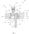
- a fuel connection unit for a fuel-operated vehicle heater is generally designated by 10.
- the fuel connection unit 10 comprises a disk-like connection unit body 12 which is inserted into an opening 14 associated therewith in a heater housing 16 of a vehicle heater generally designated 18.
- the connection unit body 12 can be surrounded by a sealing element 22, for example, in its area facing the interior 20 of the heater housing 16, which sealing element can be clamped between it and the heater housing 16.
- a latching element 24 is provided on the connection unit body 12, which engages behind a latching projection 28 in a latching recess 26 of the heater housing 16 and thus prevents the fuel connection unit 10 from being pulled out or falling out of the opening 14.
- a plurality of such latching elements 24 can be provided over the circumference of the connection unit body 12, which is provided in a disk-like shape.
- a fuel delivery line connection area 32 extends therefrom.
- This fuel delivery connection line area 32 designed in the manner of a pipe socket, has in its interior a fuel channel 34 which, on the one hand, is open to a fuel flow volume 36 formed in the connection unit body 12 and, on the other hand, receives two sealing elements 40, for example, in an enlarged end region 38.
- a funnel-like shaped holding element 42 holding the sealing elements 40 in the fuel channel 34 is carried on the end region 38, through which a fuel delivery line extending in the interior 20 of the heater housing 16 can be introduced.
- the fuel delivery line constructed for example as a rigid pipe made of metal material, is connected to the fuel delivery line area 32 in a manner secured against the escape of fuel by the clamping effect of the sealing elements 40.
- a fuel supply line connection area 46 extends from the connection unit body 12 offset to the fuel delivery connection line area 32. This is also designed in the manner of a pipe socket and in its interior provides a fuel channel 48 open to the fuel flow volume 36 in the connection unit body 12.
- a fuel line embodied as a flexible hose, for example, can be pushed onto the fuel supply line connection area 46 in order to guide fuel flowing from a fuel reservoir into the fuel flow volume 36 and via this the fuel channel 34.
- connection unit body 12 is integral with the fuel delivery line connection area 32, the fuel supply line connection area 46 and the latching element (s) 24, that is, as a material block, for example in a casting process and for example made of plastic material.
- a functional unit, generally designated 50, is provided on the connection unit body 12 of the fuel connection unit 10.
- the functional unit 50 is designed as a pulsation damper 52 and comprises a cup-like pulsation damper body 54 accommodated in a damper mounting recess 51, in which a, for example, gas, such as. B. air, filled pressure equalization volume 56 is provided.
- the pressure equalization volume 56 is closed off in the direction of the fuel flow volume 36 by a flexible, for example membrane-like separating element 58, which is firmly supported on the pulsation damper body 54.
- the pulsation damper body 54 can be pressed into the connection unit body 12 and / or can be fixed thereon or therein by a material bond, in particular gluing or welding.
- the separating element 58 can also be firmly connected to the pulsation damper body 54, for example by gluing or welding.
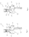
- FIGS Figs. 2 and 3 Design types of fuel connection units, which are described in more detail below, are shown in FIGS Figs. 2 and 3 shown.
- a fuel valve, generally designated 60 is arranged in the connection unit body 12 as a functional unit 50 in the embodiment shown. This can establish or block a flow connection between the fuel channels 48, 34 in order to prevent the entry of fuel into the vehicle heater 18 or to prevent the outgassing of fuel vapor from the burner area of the vehicle heater 18.
- a fuel pump 62 is arranged as the functional unit 50 in the connection unit body 12 of the fuel connection unit 10. Liquid fuel conveyed from a fuel reservoir can be conveyed by the fuel pump 62 in the direction of the burner area of the vehicle heater 18.
- the Fig. 4 shows an embodiment of a connection unit 10 in which a fuel valve 60, in particular a check valve 64, is provided in the connection unit body 12 as the functional unit 50.
- connection unit body 12 is formed with two parts.
- a first connection body part 66 has the fuel delivery line connection region 32 with the fuel channel 34 formed therein, the inner end of which also forms the or a part of the fuel flow volume 36.
- the first part 66 of the connection unit body 12 is to be inserted into the opening 14 of the heater housing 16 in the manner described above and also has the latching element 24, for example.
- a second connection unit body part 68 is connected in a fluid-tight manner to the first connection unit body part 66 via an O-ring-like sealing element 70 and has the fuel supply connection area 46 with the fuel channel 48 formed therein.
- connection unit body part 68 On the second connection unit body part 68 there is formed, for example, a conically shaped valve seat 72 on which a valve member 74 embodied as a valve ball can sit.
- a pretensioning element 76 designed as a helical compression spring is supported on the one hand on a section 78 of the first connection unit body part 66 that is also positioned so as to engage in the second connection unit body part 68 and presses the valve element 74 against its valve seat 72 of the prestressing element 76, a fuel flow through the fuel channel 48, the fuel flow volume 36 and the fuel channel 34 in the direction of a burner area of a vehicle heater is possible, a flow in the opposite direction or the escape of existing fuel gases in the burner area is, however, prevented by the check valve 64.
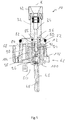
- the Fig. 5 shows a fuel connection unit 10, in which in a further development of the in Fig. 3
- a fuel pump 62 also generally referred to as a metering pump, is provided as the functional unit 50.
- the fuel pump 62 comprises in the connection unit body 12 a pump chamber insert 80 with a pump chamber 82 elongated therein in the direction of a channel longitudinal axis K.
- the pump chamber insert 80 is surrounded by a pump housing 84, which is supported on the connection unit body 12 with a sealing element 86 interposed and together with a length range of the pump chamber insert 80 forms a ring-like supply volume 90 which is open to the pump chamber 82 via openings 88.
- a pump member 94 providing a pump piston 92 can be moved back and forth in the direction of the longitudinal axis K of the channel, with the FIG Fig. 5 It should be noted that the two fuel ducts 34, 48 are arranged in alignment with one another in the direction of the longitudinal axis K of the duct.
- An armature 96 is arranged on a region of the pump piston 92 that is not in the pump chamber insert 80.
- a prestressing element 98 designed as a helical compression spring is supported, which thus prestresses the pump piston 92 in the direction out of the pump chamber 82 and into contact with a part 100 of the fuel connection unit 10 providing the fuel supply line connection area 46.
- An electromagnet unit 102 with an electrically excitable coil arrangement 104 is fixedly carried on or in the connection unit body 12 as part of a drive unit 101. By energizing the coil arrangement 104, it becomes magnetic Interaction with the armature 96 is generated, which acts on it into the interior of the electromagnet unit 102 and thus moves the pump piston 92 in the direction of reducing the fuel-filled volume of the pump chamber 82 in order to expel fuel.
- a check valve that allows the fuel flow only in the direction into the fuel channel 34 can be provided and accordingly also upstream of the pump chamber 82, for example at the end of the fuel channel 48, a check valve that allows the fuel flow only in the direction of the pump chamber 82 can be provided.
- fuel is accordingly alternately taken up via the fuel channel 48 in the pump chamber 82 and expelled from the pump chamber 82 into the fuel channel 34.
- a defined volume of fuel is ejected from the pump chamber 82 and conveyed in the direction of a burner area of the heater, so that by setting the operating frequency of such a fuel pump 62, a metered amount of the fuel to be conveyed to the burner area is pumped can be.
Landscapes
- Engineering & Computer Science (AREA)
- Mechanical Engineering (AREA)
- Physics & Mathematics (AREA)
- Thermal Sciences (AREA)
- Chemical & Material Sciences (AREA)
- Combustion & Propulsion (AREA)
- General Engineering & Computer Science (AREA)
- Air-Conditioning For Vehicles (AREA)
Priority Applications (1)
| Application Number | Priority Date | Filing Date | Title |
|---|---|---|---|
| PL19183788T PL3594572T3 (pl) | 2018-07-09 | 2019-07-02 | Nagrzewnica pojazdu z jednostką przyłączeniową paliwa |
Applications Claiming Priority (1)
| Application Number | Priority Date | Filing Date | Title |
|---|---|---|---|
| DE102018116523.4A DE102018116523B3 (de) | 2018-07-09 | 2018-07-09 | Kraftstoffanschlusseinheit |
Publications (2)
| Publication Number | Publication Date |
|---|---|
| EP3594572A1 EP3594572A1 (de) | 2020-01-15 |
| EP3594572B1 true EP3594572B1 (de) | 2021-05-05 |
Family
ID=67139669
Family Applications (1)
| Application Number | Title | Priority Date | Filing Date |
|---|---|---|---|
| EP19183788.9A Active EP3594572B1 (de) | 2018-07-09 | 2019-07-02 | Fahrzeugheizgerät mit kraftstoffanschlusseinheit |
Country Status (7)
| Country | Link |
|---|---|
| US (1) | US11479084B2 (pl) |
| EP (1) | EP3594572B1 (pl) |
| CN (1) | CN110696592B (pl) |
| CA (1) | CA3048867C (pl) |
| DE (1) | DE102018116523B3 (pl) |
| PL (1) | PL3594572T3 (pl) |
| RU (1) | RU2719710C1 (pl) |
Families Citing this family (1)
| Publication number | Priority date | Publication date | Assignee | Title |
|---|---|---|---|---|
| WO2023144587A1 (en) * | 2022-01-28 | 2023-08-03 | Ti Group Automotive Systems, Llc | Connection arrangement device and method for fluid line |
Family Cites Families (13)
| Publication number | Priority date | Publication date | Assignee | Title |
|---|---|---|---|---|
| US2290298A (en) | 1939-12-02 | 1942-07-21 | Stewart Warner Corp | Automobile heater |
| US3849055A (en) * | 1974-03-04 | 1974-11-19 | Stacee Mfg Inc | Liquid fuel heater improvement |
| DE3136839A1 (de) * | 1981-09-16 | 1983-03-31 | Webasto-Werk W. Baier GmbH & Co, 8035 Gauting | Fahrzeugheizung |
| JPH0811523A (ja) * | 1994-06-29 | 1996-01-16 | Sanden Corp | 暖房用ボイラ |
| KR100568027B1 (ko) * | 2003-06-26 | 2006-04-05 | 김연형 | 연소효율을 개선한 기화식 버너 |
| JP2005036689A (ja) * | 2003-07-18 | 2005-02-10 | Keihin Corp | 燃料供給装置 |
| DE202004015442U1 (de) * | 2004-10-05 | 2006-02-09 | J. Eberspächer GmbH & Co. KG | Steuergerät für ein Fahrzeugheizgerät zur Steuerung des Betriebs eines Luftfördergebläses |
| DE102005015116A1 (de) * | 2005-04-01 | 2006-10-05 | Webasto Ag | Kraftfahrzeugheizung |
| DE102005015117B4 (de) * | 2005-04-01 | 2007-04-26 | Webasto Ag | Hubkolbenbrennstoffpumpe und Verfahren zum Starten und Betreiben einer Kraftfahrzeugheizung |
| US20170260944A1 (en) * | 2016-03-08 | 2017-09-14 | K&N Engineering, Inc. | Universal inline fuel pump |
| DE102016107207B4 (de) * | 2016-03-17 | 2020-07-09 | Eberspächer Climate Control Systems GmbH & Co. KG | Brennstoffgasbetriebenes Fahrzeugheizgerät |
| EP3436297A1 (en) | 2016-03-30 | 2019-02-06 | Carrier Corporation | Transport refrigeration unit |
| DE102017123046A1 (de) | 2017-10-05 | 2019-04-11 | Eberspächer Climate Control Systems GmbH & Co. KG | Kraftstoffanschlusseinheit |
-
2018
- 2018-07-09 DE DE102018116523.4A patent/DE102018116523B3/de active Active
-
2019
- 2019-06-28 CN CN201910573597.1A patent/CN110696592B/zh active Active
- 2019-07-02 EP EP19183788.9A patent/EP3594572B1/de active Active
- 2019-07-02 PL PL19183788T patent/PL3594572T3/pl unknown
- 2019-07-05 RU RU2019121014A patent/RU2719710C1/ru active
- 2019-07-08 CA CA3048867A patent/CA3048867C/en active Active
- 2019-07-08 US US16/505,152 patent/US11479084B2/en active Active
Also Published As
| Publication number | Publication date |
|---|---|
| PL3594572T3 (pl) | 2021-11-15 |
| EP3594572A1 (de) | 2020-01-15 |
| CA3048867A1 (en) | 2020-01-09 |
| US11479084B2 (en) | 2022-10-25 |
| US20200009942A1 (en) | 2020-01-09 |
| CN110696592A (zh) | 2020-01-17 |
| DE102018116523B3 (de) | 2019-09-05 |
| CA3048867C (en) | 2022-06-21 |
| CN110696592B (zh) | 2023-04-28 |
| RU2719710C1 (ru) | 2020-04-22 |
Similar Documents
| Publication | Publication Date | Title |
|---|---|---|
| DE102017212726B3 (de) | Strahlpumpeneinheit zum Steuern eines gasförmigen Mediums | |
| DE102007063939B4 (de) | Hochdruckkraftstoffpumpe | |
| EP2519744A2 (de) | Pumpe mit einer ventil zugeorneten dämpfanordnung | |
| DE10231216A1 (de) | Einrichtung zur Abgasnachbehandlung von Kraftfahrzeugen, insbesondere Dieselkraftfahrzeugen | |
| WO2007124873A1 (de) | Dosierpumpe | |
| WO2009071069A1 (de) | Hubkolben-membranpumpe | |
| EP3594572B1 (de) | Fahrzeugheizgerät mit kraftstoffanschlusseinheit | |
| DE102008055611B4 (de) | Hubkolbenpumpe | |
| DE10301093A1 (de) | Dosierpumpeinrichtung für ein Fahrzeugheizgerät | |
| DE102005022661A1 (de) | Fluidpumpe, insbesondere Kraftstoff-Hochdruckpumpe für eine Brennkraftmaschine mit Kraftstoff-Direkteinspritzung | |
| EP2923066A1 (de) | Ventileinrichtung | |
| EP2012009B1 (de) | Rückschlagventileinsatz für eine Brennstoffdosierpumpe | |
| EP3150853B1 (de) | Dosierpumpe, insbesondere brennstoffdosierpumpe für ein fahrzeugheizgerät | |
| DE10234584B3 (de) | Piezoelektrisch betätigbare Pumpe | |
| DE10149412C1 (de) | Vorrichtung zum Dämpfen von Druckpulsationen in einem Fluidsystem, insbesondere in einem Kraftstoffsystem einer Brennkraftmaschine, sowie Verfahren zum Betreiben einer Brennkraftmaschine | |
| EP3295026A1 (de) | Magnetpumpe für ein hilfsaggregat eines fahrzeugs | |
| DE10103224C1 (de) | Dosierpumpanordnung und diese enthaltendes Dosierpumpsystem | |
| EP4251880B1 (de) | Pumpenvorrichtung | |
| DE102018120950A1 (de) | Dosierpumpe | |
| EP1857673A1 (de) | Dosierpumpe, insbesondere zum Fördern von Brennstoff für ein Fahrzeugheizgerät | |
| DE102019120474B4 (de) | Absperrventil für ein Brennstoffzuführsystem für ein brennstoffbetriebenes Fahrzeugheizgerät sowie Brennstoffzuführsystem für ein brennstoffbetriebenes Fahrzeugheizgerät | |
| WO2014079610A1 (de) | Vorrichtung zum einspritzen von fluiden, insbesondere pumpe-düse-system | |
| DE102004024865A1 (de) | Druckpulsationsdämpfer und Kraftstoffdosierpumpe mit einem Druckpulsationsdämpfer | |
| DE102015101066B4 (de) | Dosierpumpe, inbesondere Brennstoffdosierpumpe für ein Fahrzeugheizgerät | |
| DE102008024280A1 (de) | Dosierpumpe, insbesondere zur Brennstoffförderung in einem Fahrzeugheizgerät |
Legal Events
| Date | Code | Title | Description |
|---|---|---|---|
| PUAI | Public reference made under article 153(3) epc to a published international application that has entered the european phase |
Free format text: ORIGINAL CODE: 0009012 |
|
| STAA | Information on the status of an ep patent application or granted ep patent |
Free format text: STATUS: THE APPLICATION HAS BEEN PUBLISHED |
|
| AK | Designated contracting states |
Kind code of ref document: A1 Designated state(s): AL AT BE BG CH CY CZ DE DK EE ES FI FR GB GR HR HU IE IS IT LI LT LU LV MC MK MT NL NO PL PT RO RS SE SI SK SM TR |
|
| AX | Request for extension of the european patent |
Extension state: BA ME |
|
| STAA | Information on the status of an ep patent application or granted ep patent |
Free format text: STATUS: REQUEST FOR EXAMINATION WAS MADE |
|
| 17P | Request for examination filed |
Effective date: 20200715 |
|
| RBV | Designated contracting states (corrected) |
Designated state(s): AL AT BE BG CH CY CZ DE DK EE ES FI FR GB GR HR HU IE IS IT LI LT LU LV MC MK MT NL NO PL PT RO RS SE SI SK SM TR |
|
| RAP1 | Party data changed (applicant data changed or rights of an application transferred) |
Owner name: EBERSPAECHER CLIMATE CONTROL SYSTEMS GMBH |
|
| GRAP | Despatch of communication of intention to grant a patent |
Free format text: ORIGINAL CODE: EPIDOSNIGR1 |
|
| STAA | Information on the status of an ep patent application or granted ep patent |
Free format text: STATUS: GRANT OF PATENT IS INTENDED |
|
| INTG | Intention to grant announced |
Effective date: 20210114 |
|
| GRAJ | Information related to disapproval of communication of intention to grant by the applicant or resumption of examination proceedings by the epo deleted |
Free format text: ORIGINAL CODE: EPIDOSDIGR1 |
|
| STAA | Information on the status of an ep patent application or granted ep patent |
Free format text: STATUS: REQUEST FOR EXAMINATION WAS MADE |
|
| GRAP | Despatch of communication of intention to grant a patent |
Free format text: ORIGINAL CODE: EPIDOSNIGR1 |
|
| STAA | Information on the status of an ep patent application or granted ep patent |
Free format text: STATUS: GRANT OF PATENT IS INTENDED |
|
| GRAS | Grant fee paid |
Free format text: ORIGINAL CODE: EPIDOSNIGR3 |
|
| GRAA | (expected) grant |
Free format text: ORIGINAL CODE: 0009210 |
|
| STAA | Information on the status of an ep patent application or granted ep patent |
Free format text: STATUS: THE PATENT HAS BEEN GRANTED |
|
| INTC | Intention to grant announced (deleted) | ||
| INTG | Intention to grant announced |
Effective date: 20210323 |
|
| REG | Reference to a national code |
Ref country code: DE Ref legal event code: R082 Ref document number: 502019001353 Country of ref document: DE Representative=s name: RUTTENSPERGER LACHNIT TROSSIN GOMOLL, PATENT- , DE |
|
| AK | Designated contracting states |
Kind code of ref document: B1 Designated state(s): AL AT BE BG CH CY CZ DE DK EE ES FI FR GB GR HR HU IE IS IT LI LT LU LV MC MK MT NL NO PL PT RO RS SE SI SK SM TR |
|
| REG | Reference to a national code |
Ref country code: GB Ref legal event code: FG4D Free format text: NOT ENGLISH |
|
| REG | Reference to a national code |
Ref country code: CH Ref legal event code: EP |
|
| REG | Reference to a national code |
Ref country code: AT Ref legal event code: REF Ref document number: 1390272 Country of ref document: AT Kind code of ref document: T Effective date: 20210515 |
|
| REG | Reference to a national code |
Ref country code: IE Ref legal event code: FG4D Free format text: LANGUAGE OF EP DOCUMENT: GERMAN |
|
| REG | Reference to a national code |
Ref country code: DE Ref legal event code: R096 Ref document number: 502019001353 Country of ref document: DE |
|
| REG | Reference to a national code |
Ref country code: SE Ref legal event code: TRGR |
|
| REG | Reference to a national code |
Ref country code: FI Ref legal event code: FGE |
|
| REG | Reference to a national code |
Ref country code: LT Ref legal event code: MG9D |
|
| PG25 | Lapsed in a contracting state [announced via postgrant information from national office to epo] |
Ref country code: BG Free format text: LAPSE BECAUSE OF FAILURE TO SUBMIT A TRANSLATION OF THE DESCRIPTION OR TO PAY THE FEE WITHIN THE PRESCRIBED TIME-LIMIT Effective date: 20210805 Ref country code: LT Free format text: LAPSE BECAUSE OF FAILURE TO SUBMIT A TRANSLATION OF THE DESCRIPTION OR TO PAY THE FEE WITHIN THE PRESCRIBED TIME-LIMIT Effective date: 20210505 Ref country code: HR Free format text: LAPSE BECAUSE OF FAILURE TO SUBMIT A TRANSLATION OF THE DESCRIPTION OR TO PAY THE FEE WITHIN THE PRESCRIBED TIME-LIMIT Effective date: 20210505 |
|
| PG25 | Lapsed in a contracting state [announced via postgrant information from national office to epo] |
Ref country code: RS Free format text: LAPSE BECAUSE OF FAILURE TO SUBMIT A TRANSLATION OF THE DESCRIPTION OR TO PAY THE FEE WITHIN THE PRESCRIBED TIME-LIMIT Effective date: 20210505 Ref country code: PT Free format text: LAPSE BECAUSE OF FAILURE TO SUBMIT A TRANSLATION OF THE DESCRIPTION OR TO PAY THE FEE WITHIN THE PRESCRIBED TIME-LIMIT Effective date: 20210906 Ref country code: NO Free format text: LAPSE BECAUSE OF FAILURE TO SUBMIT A TRANSLATION OF THE DESCRIPTION OR TO PAY THE FEE WITHIN THE PRESCRIBED TIME-LIMIT Effective date: 20210805 Ref country code: LV Free format text: LAPSE BECAUSE OF FAILURE TO SUBMIT A TRANSLATION OF THE DESCRIPTION OR TO PAY THE FEE WITHIN THE PRESCRIBED TIME-LIMIT Effective date: 20210505 Ref country code: GR Free format text: LAPSE BECAUSE OF FAILURE TO SUBMIT A TRANSLATION OF THE DESCRIPTION OR TO PAY THE FEE WITHIN THE PRESCRIBED TIME-LIMIT Effective date: 20210806 Ref country code: IS Free format text: LAPSE BECAUSE OF FAILURE TO SUBMIT A TRANSLATION OF THE DESCRIPTION OR TO PAY THE FEE WITHIN THE PRESCRIBED TIME-LIMIT Effective date: 20210905 |
|
| REG | Reference to a national code |
Ref country code: NL Ref legal event code: MP Effective date: 20210505 |
|
| PG25 | Lapsed in a contracting state [announced via postgrant information from national office to epo] |
Ref country code: NL Free format text: LAPSE BECAUSE OF FAILURE TO SUBMIT A TRANSLATION OF THE DESCRIPTION OR TO PAY THE FEE WITHIN THE PRESCRIBED TIME-LIMIT Effective date: 20210505 |
|
| PG25 | Lapsed in a contracting state [announced via postgrant information from national office to epo] |
Ref country code: SM Free format text: LAPSE BECAUSE OF FAILURE TO SUBMIT A TRANSLATION OF THE DESCRIPTION OR TO PAY THE FEE WITHIN THE PRESCRIBED TIME-LIMIT Effective date: 20210505 Ref country code: RO Free format text: LAPSE BECAUSE OF FAILURE TO SUBMIT A TRANSLATION OF THE DESCRIPTION OR TO PAY THE FEE WITHIN THE PRESCRIBED TIME-LIMIT Effective date: 20210505 Ref country code: DK Free format text: LAPSE BECAUSE OF FAILURE TO SUBMIT A TRANSLATION OF THE DESCRIPTION OR TO PAY THE FEE WITHIN THE PRESCRIBED TIME-LIMIT Effective date: 20210505 Ref country code: SK Free format text: LAPSE BECAUSE OF FAILURE TO SUBMIT A TRANSLATION OF THE DESCRIPTION OR TO PAY THE FEE WITHIN THE PRESCRIBED TIME-LIMIT Effective date: 20210505 Ref country code: EE Free format text: LAPSE BECAUSE OF FAILURE TO SUBMIT A TRANSLATION OF THE DESCRIPTION OR TO PAY THE FEE WITHIN THE PRESCRIBED TIME-LIMIT Effective date: 20210505 Ref country code: ES Free format text: LAPSE BECAUSE OF FAILURE TO SUBMIT A TRANSLATION OF THE DESCRIPTION OR TO PAY THE FEE WITHIN THE PRESCRIBED TIME-LIMIT Effective date: 20210505 |
|
| REG | Reference to a national code |
Ref country code: DE Ref legal event code: R097 Ref document number: 502019001353 Country of ref document: DE |
|
| PLBE | No opposition filed within time limit |
Free format text: ORIGINAL CODE: 0009261 |
|
| STAA | Information on the status of an ep patent application or granted ep patent |
Free format text: STATUS: NO OPPOSITION FILED WITHIN TIME LIMIT |
|
| PG25 | Lapsed in a contracting state [announced via postgrant information from national office to epo] |
Ref country code: MC Free format text: LAPSE BECAUSE OF FAILURE TO SUBMIT A TRANSLATION OF THE DESCRIPTION OR TO PAY THE FEE WITHIN THE PRESCRIBED TIME-LIMIT Effective date: 20210505 |
|
| REG | Reference to a national code |
Ref country code: BE Ref legal event code: MM Effective date: 20210731 |
|
| 26N | No opposition filed |
Effective date: 20220208 |
|
| PG25 | Lapsed in a contracting state [announced via postgrant information from national office to epo] |
Ref country code: IS Free format text: LAPSE BECAUSE OF FAILURE TO SUBMIT A TRANSLATION OF THE DESCRIPTION OR TO PAY THE FEE WITHIN THE PRESCRIBED TIME-LIMIT Effective date: 20210905 Ref country code: LU Free format text: LAPSE BECAUSE OF NON-PAYMENT OF DUE FEES Effective date: 20210702 Ref country code: AL Free format text: LAPSE BECAUSE OF FAILURE TO SUBMIT A TRANSLATION OF THE DESCRIPTION OR TO PAY THE FEE WITHIN THE PRESCRIBED TIME-LIMIT Effective date: 20210505 |
|
| PG25 | Lapsed in a contracting state [announced via postgrant information from national office to epo] |
Ref country code: IT Free format text: LAPSE BECAUSE OF FAILURE TO SUBMIT A TRANSLATION OF THE DESCRIPTION OR TO PAY THE FEE WITHIN THE PRESCRIBED TIME-LIMIT Effective date: 20210505 Ref country code: IE Free format text: LAPSE BECAUSE OF NON-PAYMENT OF DUE FEES Effective date: 20210702 Ref country code: BE Free format text: LAPSE BECAUSE OF NON-PAYMENT OF DUE FEES Effective date: 20210731 |
|
| REG | Reference to a national code |
Ref country code: CH Ref legal event code: PL |
|
| PG25 | Lapsed in a contracting state [announced via postgrant information from national office to epo] |
Ref country code: LI Free format text: LAPSE BECAUSE OF NON-PAYMENT OF DUE FEES Effective date: 20220731 Ref country code: CH Free format text: LAPSE BECAUSE OF NON-PAYMENT OF DUE FEES Effective date: 20220731 |
|
| PG25 | Lapsed in a contracting state [announced via postgrant information from national office to epo] |
Ref country code: CY Free format text: LAPSE BECAUSE OF FAILURE TO SUBMIT A TRANSLATION OF THE DESCRIPTION OR TO PAY THE FEE WITHIN THE PRESCRIBED TIME-LIMIT Effective date: 20210505 |
|
| PG25 | Lapsed in a contracting state [announced via postgrant information from national office to epo] |
Ref country code: HU Free format text: LAPSE BECAUSE OF FAILURE TO SUBMIT A TRANSLATION OF THE DESCRIPTION OR TO PAY THE FEE WITHIN THE PRESCRIBED TIME-LIMIT; INVALID AB INITIO Effective date: 20190702 |
|
| GBPC | Gb: european patent ceased through non-payment of renewal fee |
Effective date: 20230702 |
|
| PG25 | Lapsed in a contracting state [announced via postgrant information from national office to epo] |
Ref country code: MK Free format text: LAPSE BECAUSE OF FAILURE TO SUBMIT A TRANSLATION OF THE DESCRIPTION OR TO PAY THE FEE WITHIN THE PRESCRIBED TIME-LIMIT Effective date: 20210505 Ref country code: GB Free format text: LAPSE BECAUSE OF NON-PAYMENT OF DUE FEES Effective date: 20230702 |
|
| PG25 | Lapsed in a contracting state [announced via postgrant information from national office to epo] |
Ref country code: MT Free format text: LAPSE BECAUSE OF FAILURE TO SUBMIT A TRANSLATION OF THE DESCRIPTION OR TO PAY THE FEE WITHIN THE PRESCRIBED TIME-LIMIT Effective date: 20210505 |
|
| PGFP | Annual fee paid to national office [announced via postgrant information from national office to epo] |
Ref country code: PL Payment date: 20250623 Year of fee payment: 7 |
|
| PGFP | Annual fee paid to national office [announced via postgrant information from national office to epo] |
Ref country code: CZ Payment date: 20250619 Year of fee payment: 7 |
|
| REG | Reference to a national code |
Ref country code: AT Ref legal event code: MM01 Ref document number: 1390272 Country of ref document: AT Kind code of ref document: T Effective date: 20240702 |
|
| PGFP | Annual fee paid to national office [announced via postgrant information from national office to epo] |
Ref country code: FI Payment date: 20250722 Year of fee payment: 7 |
|
| PGFP | Annual fee paid to national office [announced via postgrant information from national office to epo] |
Ref country code: DE Payment date: 20250731 Year of fee payment: 7 |
|
| PG25 | Lapsed in a contracting state [announced via postgrant information from national office to epo] |
Ref country code: AT Free format text: LAPSE BECAUSE OF NON-PAYMENT OF DUE FEES Effective date: 20240702 |
|
| PGFP | Annual fee paid to national office [announced via postgrant information from national office to epo] |
Ref country code: FR Payment date: 20250723 Year of fee payment: 7 |
|
| PGFP | Annual fee paid to national office [announced via postgrant information from national office to epo] |
Ref country code: SE Payment date: 20250723 Year of fee payment: 7 |
|
| PG25 | Lapsed in a contracting state [announced via postgrant information from national office to epo] |
Ref country code: TR Free format text: LAPSE BECAUSE OF FAILURE TO SUBMIT A TRANSLATION OF THE DESCRIPTION OR TO PAY THE FEE WITHIN THE PRESCRIBED TIME-LIMIT Effective date: 20210505 |