EP3593751B1 - Outil de dentisterie - Google Patents
Outil de dentisterie Download PDFInfo
- Publication number
- EP3593751B1 EP3593751B1 EP19186061.8A EP19186061A EP3593751B1 EP 3593751 B1 EP3593751 B1 EP 3593751B1 EP 19186061 A EP19186061 A EP 19186061A EP 3593751 B1 EP3593751 B1 EP 3593751B1
- Authority
- EP
- European Patent Office
- Prior art keywords
- drill bit
- core
- bone
- implant
- cutting
- Prior art date
- Legal status (The legal status is an assumption and is not a legal conclusion. Google has not performed a legal analysis and makes no representation as to the accuracy of the status listed.)
- Active
Links
- 238000005520 cutting process Methods 0.000 claims description 136
- 239000007943 implant Substances 0.000 claims description 82
- 239000004053 dental implant Substances 0.000 claims description 14
- 210000000988 bone and bone Anatomy 0.000 description 110
- 238000003780 insertion Methods 0.000 description 49
- 230000037431 insertion Effects 0.000 description 49
- 238000005553 drilling Methods 0.000 description 40
- 238000000034 method Methods 0.000 description 35
- 230000006835 compression Effects 0.000 description 22
- 238000007906 compression Methods 0.000 description 22
- 238000006073 displacement reaction Methods 0.000 description 9
- 230000002262 irrigation Effects 0.000 description 9
- 238000003973 irrigation Methods 0.000 description 9
- 238000010606 normalization Methods 0.000 description 9
- 230000006837 decompression Effects 0.000 description 8
- 230000007704 transition Effects 0.000 description 8
- 238000011084 recovery Methods 0.000 description 7
- 238000005259 measurement Methods 0.000 description 6
- 230000006870 function Effects 0.000 description 5
- 238000002513 implantation Methods 0.000 description 5
- 230000007423 decrease Effects 0.000 description 4
- 230000008901 benefit Effects 0.000 description 3
- 230000015572 biosynthetic process Effects 0.000 description 3
- 238000010883 osseointegration Methods 0.000 description 3
- 238000001356 surgical procedure Methods 0.000 description 3
- 230000008859 change Effects 0.000 description 2
- 230000002301 combined effect Effects 0.000 description 2
- 230000007774 longterm Effects 0.000 description 2
- 238000012986 modification Methods 0.000 description 2
- 230000004048 modification Effects 0.000 description 2
- 238000002360 preparation method Methods 0.000 description 2
- 241000219470 Mirabilis Species 0.000 description 1
- 238000013459 approach Methods 0.000 description 1
- 239000008280 blood Substances 0.000 description 1
- 210000004369 blood Anatomy 0.000 description 1
- 230000037182 bone density Effects 0.000 description 1
- 238000006243 chemical reaction Methods 0.000 description 1
- 239000003795 chemical substances by application Substances 0.000 description 1
- 230000000694 effects Effects 0.000 description 1
- 238000011156 evaluation Methods 0.000 description 1
- 238000009472 formulation Methods 0.000 description 1
- 230000035876 healing Effects 0.000 description 1
- 230000008676 import Effects 0.000 description 1
- 238000004519 manufacturing process Methods 0.000 description 1
- 239000000463 material Substances 0.000 description 1
- 239000000203 mixture Substances 0.000 description 1
- 125000006850 spacer group Chemical group 0.000 description 1
- 238000005406 washing Methods 0.000 description 1
Images


Classifications
-
- A—HUMAN NECESSITIES
- A61—MEDICAL OR VETERINARY SCIENCE; HYGIENE
- A61B—DIAGNOSIS; SURGERY; IDENTIFICATION
- A61B17/00—Surgical instruments, devices or methods, e.g. tourniquets
- A61B17/16—Bone cutting, breaking or removal means other than saws, e.g. Osteoclasts; Drills or chisels for bones; Trepans
- A61B17/1613—Component parts
- A61B17/1615—Drill bits, i.e. rotating tools extending from a handpiece to contact the worked material
-
- A—HUMAN NECESSITIES
- A61—MEDICAL OR VETERINARY SCIENCE; HYGIENE
- A61B—DIAGNOSIS; SURGERY; IDENTIFICATION
- A61B17/00—Surgical instruments, devices or methods, e.g. tourniquets
- A61B17/16—Bone cutting, breaking or removal means other than saws, e.g. Osteoclasts; Drills or chisels for bones; Trepans
- A61B17/1655—Bone cutting, breaking or removal means other than saws, e.g. Osteoclasts; Drills or chisels for bones; Trepans for tapping
-
- A—HUMAN NECESSITIES
- A61—MEDICAL OR VETERINARY SCIENCE; HYGIENE
- A61B—DIAGNOSIS; SURGERY; IDENTIFICATION
- A61B17/00—Surgical instruments, devices or methods, e.g. tourniquets
- A61B17/16—Bone cutting, breaking or removal means other than saws, e.g. Osteoclasts; Drills or chisels for bones; Trepans
- A61B17/1662—Bone cutting, breaking or removal means other than saws, e.g. Osteoclasts; Drills or chisels for bones; Trepans for particular parts of the body
- A61B17/1673—Bone cutting, breaking or removal means other than saws, e.g. Osteoclasts; Drills or chisels for bones; Trepans for particular parts of the body for the jaw
-
- A—HUMAN NECESSITIES
- A61—MEDICAL OR VETERINARY SCIENCE; HYGIENE
- A61C—DENTISTRY; APPARATUS OR METHODS FOR ORAL OR DENTAL HYGIENE
- A61C3/00—Dental tools or instruments
- A61C3/02—Tooth drilling or cutting instruments; Instruments acting like a sandblast machine
-
- A—HUMAN NECESSITIES
- A61—MEDICAL OR VETERINARY SCIENCE; HYGIENE
- A61C—DENTISTRY; APPARATUS OR METHODS FOR ORAL OR DENTAL HYGIENE
- A61C8/00—Means to be fixed to the jaw-bone for consolidating natural teeth or for fixing dental prostheses thereon; Dental implants; Implanting tools
- A61C8/0089—Implanting tools or instruments
Definitions
- the present disclosure relates generally to a drill bit that can be used in surgery and, in certain embodiments, to drill bits used in dental surgery or to a tool to enlarge an osteotomy.
- Holes are often formed in the jawbones of patients in various circumstances and implantation situations. It is known that proper preparation of an implant-receiving hole can be important to achieving osseointegration and long-term success of the dental implant. Given that the density, orientation and quality of bone can differ from patient to patient, it is often necessary to use multiple tools and/or to have different drilling protocols available to prepare the implant-receiving hole according to the density, orientation and quality of the patient's jawbone. For example, depending upon the density of the bone at the implantation site, a different set of tools and/or drill protocols can be used to remove high-density bone from the hole as compared to an implantation site with low-density bone.
- US6217267B discloses a cold forming tap with an internal finish cutting edge includes an external thread portion having radially outwardly protruding portions and relief portions which are alternately located in a helical direction in which an external thread extends.
- One aspect of the disclosure herein is the recognition that there is a need to simplify and improve the hole formation function so that fewer drilling stages and/or protocols are needed and so that the result of the hole formation is still satisfactory.
- Another aspect of the disclosure herein is the recognition that it would be advantageous the number of instruments and drills can be reduced without compromising the precision of the hole formation across a range of bone quality, density and/or orientation situations.
- a drill bit comprising:
- the first cutting edge may be disposed within the first compression zone of the drill bit core.
- the first cutting edge may be a first radial distance from the longitudinal axis and a maximum outer dimension of the drill bit core may be a second radial distance from the longitudinal axis.
- the second radial distance may be larger than the first radial distance.
- the extremity of the first radial distance may be different than the extremity of the second radial distance.
- the extremity of the first radial distance may be at a different angular position than the extremity of the second radial distance. In other words, the first cutting edge may be at a different angular position than a maximum outer dimension of the drill bit core.
- a drill bit comprising:
- the drill bit may further comprise a guide thread which extends radially outward from the drill bit core.
- the drill bit disclosed can comprise the following features taken alone or in combination:
- the guide thread may have a height that is defined as the distance the guide thread extends radially away from the drill bit core.
- the height of the guide thread may be in the range of between 0 and 1000 ⁇ m, between 0 and 500 ⁇ m, or between 50 and 250 ⁇ m. In particular, the height of the guide thread may be 300 ⁇ m.
- the guide thread may have a width of 250 ⁇ m or less, 200 ⁇ m or less, or 150 ⁇ m or less.
- the guide thread may have a pitch of 1 mm or less.
- the guide thread may have a substantially round profile, e.g., a substantially circular profile, when viewed in a plane perpendicular to the longitudinal axis.
- the width of the guide thread may be different from the width of the cutting flute.
- the height of the guide thread may be different from the height of the cutting flute.
- the pitch of the guide thread may be different from the pitch of the cutting flute.
- the cutting flute may have an opening with an angular length in the range of between 50° and 70°.
- the angular length of the opening of the cutting flute may be 60°.
- a method of preparing an osteotomy comprising: drilling a hole in a jaw bone with a non-round or non-circular drill bit.
- the method can further comprise the following steps taken alone or in combination:
- a method of implanting an implant into a jaw bone comprising:
- the method can further comprise the following steps of:
- kit of parts comprising a drill bit of the first aspect or the second aspect and an implant, in particular a dental implant.
- the implant may comprise a thread.
- the drill bit may comprise a guide thread which extends radially outward from the drill bit core.
- the guide thread may differ from the thread of the implant in pitch and/or height and/or width.
- Figure 1 depicts an example traditional dental drill bit 10 drilling a hole 20 into a jaw bone 30 in order to prepare the jaw bone 30 for receiving a dental implant.
- Long-term success of a dental implant can depend on proper preparation of the implant site.
- the torque required to advance the implant into the jaw bone 30 also referred to as "insertion torque"
- Implant stability can be an important factor for implant osseointegration and immediate loading.
- the jaw bone 30 can consist of different bone types and/or each patient may have a jawbone of different quality, orientation and/or density
- the method of preparing the jawbone 30 to receive an implant may need to be tailored according to the density, orientation and/or quality of the bone at the site of implantation.
- Figure 2 illustrates a traditional method of preparing the jaw bone 30 to receive a dental implant that employs relatively complex drill protocols with multiple steps and decisions, especially for dense bone situations.
- a dense bone drilling protocol may include up to seven drills and taps, including: a precision drill 11, a 2-mm-diameter tapered drill 13, a first direction indicator 15, a 3.5-mm-diameter tapered drill 17, a 4.3-mm-diameter tapered drill 19, a 5.0-mm-diameter tapered drill 21, a second direction indicator 23, a 5.0-mm-diameter dense bone drill 25, and a 5.0-mm-diameter screw tap tapered drill 27.
- Dental implant manufacturers provide guidelines on which combination of tools to use, in which bone quality situations, to achieve the desired insertion torques. In some situation, a clinician must first estimate local bone quality before choosing which drill protocol to follow. If the estimation of bone quality is incorrect, the chosen drill protocol may also be incorrect, which can lead to an insertion torque that is too high or too low.
- One aspect of the present disclosure is the recognition that in regions having low-density bone, insertion torques can be improved by leaving the low-density bone in place. Moreover, in regions of high-density bone, it can be desired to remove the high-density bone from the site of implantation in order to make room for the incoming implant. Accordingly, it would be advantageous to have an instrument and/or method that can selectively cut away high-density bone from the implant site while leaving low-density bone in place. Such an instrument and/or method may also advantageously simplify drill protocol procedures.
- FIG. 3A shows a non-limiting, illustrative embodiment of a drill bit 100 having certain features and advantages of the present disclosure.
- the drill bit 100 can have a longitudinal axis 102, an apical end 104, and a coronal end 106.
- the drill bit 100 is tapered so that the outer dimension of the drill bit 100 decreases as the drill bit 100 extends toward the apical end 104, as shown in FIG. 3A .
- the drill bit 100 is not tapered.
- the outer dimension of the drill bit 100 can remain substantially constant as the drill bit 100 extends toward the apical end 104.
- the drill bit 100 can also include an attachment 110 by which the drill bit 100 can be connected to a drilling machine (not shown) and/or handle (not shown).
- the attachment 110 can be at the coronal end 106 of the drill bit 100 and can be in certain embodiments coupled to the drill bit 100 and/or formed integrally with the drill bit 100.
- the drill bit 100 can be rotated about the longitudinal axis 102 as described below to form a hole in a patient's jawbone.
- the drill bit 100 can have a guide thread 113 that extends radially outward from a drill bit core 120 of the drill bit 100.
- drill bit core 120 is tapered so that the outer dimension of the drill bit core 120 decreases as the drill bit 100 extends toward the apical end 104.
- the drill bit core can have substantially cylindrical or taper in a different manner.
- the guide thread 113 is not a working tap but is instead configured to guide the drill bit 100 in and out of the bone in a controlled manner while allowing measurement of the insertion torque to determine the bone quality.
- the guide thread 113 can aid in providing an objective measurement ofbone quality and thereby reduce error that may arise from a subjective determination of the clinician regarding bone quality.
- the guide thread 113 controls the insertion speed relative to the number of revolutions of the drill bit 100.
- the full insertion of the drill bit 100 in the bone is reached after a constant number of revolutions and therefore, after full insertion, the maximum torque measured by the drill unit or a torque wrench is directly related to the average bone quality over the length.
- the decision to use one drilling protocol over another can be based on the insertion torque of the drill bit 100. For example, if the insertion torque is below a certain level, the clinician may elect to use a drilling protocol that is designed for low-density bone.
- the clinician may elect to use a drilling protocol that is designed for high-density bone.
- the full insertion depth may not be needed (for example in case of soft bone), thus creating a shorter and smaller osteotomy. This would be the case in low quality or softer bone.
- the bone density may vary from 16g/cm3 (soft bone) to 80g/cm3 (hard bone). In hard bone, the tool would be used to the full depth, thus creating a longer and larger osteotomy.
- the guide thread 113 can be adapted to allow the drill bit 100 to be advanced into the bone in a controlled fashion, at a low speed (e.g., about 10-100 rpm), without irrigation, or a combination thereof.
- Low-speed drilling can generate less heat than high-speed drilling, making low-speed drilling potentially less harmful to the bone tissue than high-speed drilling.
- Drilling methods that avoid irrigation can have biological benefits for bone healing by not removing (e.g., washing) bone chips and blood out of the osteotomy.
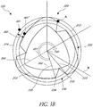
- Figure 3B shows a transverse cross-sectional view of the drill bit core 120 of the drill bit 100 taken a point along the longitudinal axis 102 of the drill bit 100.
- the guide thread 113 is not shown on the outer surface of the drill bit core 120 in the cross-sectional view.
- the drill bit core 120 can have a non-round or non-circular cross-sectional shape along a length 1 (in the longitudinal direction) of the drill bit 100 with the cross-sectional shape being taken along a plane that is generally perpendicular to the longitudinal axis 102 of the drill bit 100 as shown in Figure 3A .
- the drill bit core 120 has a non-round cross-sectional shape over the entire length of the drill bit core 120 (or of the portion of the drill bit 100 intended to be in contact with the bone) and in certain embodiments, the non-round cross-sectional shape can extend over 50 to 90% of the length of the drill bit core 120.
- the shape of non-round cross-sectional shape of the drill bit core 120 can remain generally constant over the length of the drill bit core 120.
- the drill bit core 120 tapers such that the outer dimension of the drill bit core 120 decreases as the drill bit 100 extends toward the apical end 104
- the non-round cross-sectional shape of the drill bit core 120 can remain generally constant while changing in dimensions.
- the drill bit core 120 can have more than one non-round cross-sectional shape over the length of the drill bit core 120.
- the drill bit core 120 can have a minimum radius 202 and a maximum radius 204.
- the drill bit 100 can be rotated about the longitudinal axis 102, as indicated in Figure 3B by the semi-circular arrow 201.
- the minimum radius 202 will sweep out an inner circle 212
- the maximum radius 204 will sweep out an outer circle 214.
- a reference point on the surrounding bone will be pushed radially outward as the maximum radius 204 approaches the reference point.
- the reference point can reach a maximum displacement 301 when the maximum radius 204 arrives at the reference point.
- the reference point can move radially inward to occupy the space vacated by the rotating drill bit 100.
- the reference point can reach a minimum displacement 301' when the minimum radius 202 arrives at the reference point. In this way, the surrounding bone can move back and forth across a working margin 302, as indicated by the double-headed arrow in Figure 3B .
- the drill bit 100 can form a compression zone 220 corresponding to the region of the drill bit 100 that compresses the surrounding bone.
- the compression zone 220 extends from the maximum radius at the twelve o'clock position of the drill bit core 120 to the minimum radius at the two o'clock position of the drill bit core 120.
- the drill bit 100 can have a decompression zone 222 corresponding to the region of the drill bit 100 that allows decompression of the surrounding bone.
- the decompression zone 222 can extend from the minimum radius at the two o'clock position of the drill bit core 120 to the maximum radius at the four o'clock position of the drill bit core 120.
- the drill bit 100 can include more than one compression zones 220 and decompression zones 222.
- the tri-oval embodiment of Figure 3B has three compression zones 220 and three decompression zones 222.
- Modified embodiments can include more or less compression zones and/or three compression zones with different shapes.
- the drill bit core 120 can have regions in which the non-round cross-sectional shape of the drill bit core 120 can be different or change.
- tri-oval embodiment includes three compression and decompression zones that have similar dimensions that fluctuate from the same maximum radius to minimum radius.
- the compression and decompression zones can fluctuate from maximum radii to minimum radii of different dimensions such that a different amount of compression and/or decompression occurs in each zone.
- an aspect of certain embodiments of the disclosure is the recognition that the surrounding bone can have a recovery time defined as the time required for the surrounding bone to move from the maximum displacement 301 to the minimum displacement 301'.
- the recovery time of the surrounding bone can depend on the quality of the bone. For example, hard bone can have a shorter recovery time compared to soft bone. Thus, hard bone will tend to move more quickly from the maximum displacement 301 to the minimum displacement 301' than will soft bone.
- the drill bit 100 can be adapted to exploit the difference in recovery times between the hard and soft bone so that the drill bit 100 can selectively cuts hard bone while leaving soft bone intact or disproportionately cut hard bone as compared to softer bone.
- the drill bit core 120 can include a cutting flute 230.
- the cutting flute 230 can have a cutting edge 232 and a trailing edge 234.
- the cutting edge 232 can be a cutting distance 233 from the longitudinal axis 102, which will be equal to the radius or rotation of the cutting edge 232.
- the trailing edge 234 can be a trailing distance 235 from the longitudinal axis 102, which will be the radius of rotation of the trailing edge 234.
- the cutting flute 230 can be positioned in the compression zone 220, as illustrated in Figure 3B . Referring to Figure 3B , by positioning the cutting flute 230 in the compression zone 220, the cutting distance 233 can be larger than the trailing distance 235.
- the cutting edge 232 can be positioned within the working margin 302, as illustrated in Figure 3B .
- the cutting distance 233 can be intermediate to the maximum displacement 301 and minimum displacement 301' of the surrounding bone.
- the cutting edge 232 can sweep out a cutting circle 213 that can be interposed between the inner and outer circles 212, 214 that are swept out by the minimum and maximum radii of the drill bit core 120.
- the region between the outer circle 214 and the intermediate circle 213 represents a "no-cutting" zone because bone in this region will not encounter the cutting edge 232 as the cutting edge 232 passes by the bone.
- the width of the "no-cutting" zone can be about 50 ⁇ m.
- the region between the intermediate circle 213 and the inner circle 212 represents a "cutting" zone because bone in this region will be cut by the cutting edge 232 as the cutting edge 232 passes by the bone.
- a rotation time can be defined as the time needed for the cutting edge 232 to travel the distance between the cutting edge 232 and the preceding maximum of the drill bit core 120. Referring to Figure 3B , RT would be equal to the time needed for point A to travel to line B.
- a soft bone recovery time can be defined as the time needed for the soft bone to return from the outer circle 214 to the intermediate circle 213.
- a hard bone recovery time can be defined as the time needed for hard bone to return from the outer circle 214 to the intermediate circle 213.
- the drill bit 100 and drill speed e.g., rpm
- the drill bit 100 and drill speed can be tuned so that two criteria are met: (1) SBRT > RT, thereby avoiding cutting soft bone; and (2) HBRT ⁇ RT, thereby cutting hard bone.
- Parameters that can be considered when designing the drill bit 100 include: the difference in recovery times between hard and soft bone, the difference between the maximum radius of the drill bit core 120 and the radius of the cutting edge 232, the circumferential placement of the cutting flute 230, the rotational speed of the drill bit 100, the rate of radial change of the outer surface of the drill bit core 120, and the insertion speed of the drill bit 100.
- the drill bit 100 of the present disclosure can include different configurations of the drill bit core 120.
- the drill bit 100 can include a plurality of tri-oval drill bit cores 120 that are interlinked in a helical configuration to form a screw-like structure that extends to the apical end 104 of the drill bit 100.
- the drill bit cores 120 of the illustrated drill bit 100 can taper in the apical direction.
- the outer dimension of the drill bit cores 120 can remain substantially constant along the length of the drill bit 100.
- the cutting edges 232 of the drill bit core 120 can be aligned with one another along a line 107 that extends from the apical end 104 toward the coronal end 106 of the drill bit 100, thereby forming a straight or substantially straight cutting flute 230 in which the line 107 extends generally parallel to the longitudinal axis 102 of the drill bit 100.
- the cutting edges 232 of the drill bit core 120 can be aligned with one another along a curve 109 that extends from the apical end 104 toward the coronal end 106 of the drill bit 100, thereby forming a curved cutting flute 232.
- the drill bit core 120 can taper or can have a substantially constant outer dimension along the length of the drill bit 100.
- the curve 109 bends generally in the same direction of a helical thread on the drill bit core 120 (e.g., counterclockwise toward the coronal end 106). In some variants, the curve 109 can bend generally in the direction opposite of the helical thread of the drill bit cores 120.
- the drill bit 100 can include a plurality of planar tri-oval drill bit cores 120 that are aligned substantially perpendicular to the longitudinal axis 102 of the drill bit.
- the planar tri-oval drill bit cores 120 can be spaced apart from one another, thereby forming a gap 111 between adjacent planar tri-oval drill bit cores 120.
- the drill bit cores 120 near the apical end 104 of the drill bit 100 have a smaller outer dimension than the drill bit cores 120 toward the coronal end 106 of the drill bit. In other words, the drill bit 100 tapers toward the apical end 104.
- the outer dimension of the drill bit cores 120 can remain substantially constant along the length of the drill bit 100.
- the cutting surfaces 232 of adjacent drill bit cores 120 are circumferentially shifted relative to one another so that the cutting surfaces 232 lie along a curve 109, thereby forming a disjointed cutting flute 230 that spirals around the outer surface of the drill bit 100.
- the cutting surfaces 232 of the plurality of planar tri-oval drill bit cores 120 align with one another along a line, as described above with regard to Figure 4A .
- the maximum outer dimension of the drill bit core 120 can taper and shift circumferentially in the apical direction in an uninterrupted manner, thereby producing a spiraling and continuous cutting flute 230.
- a spiraling cutting flute can facilitate removal of cut material (e.g., bone chips) from the osteotomy, as discussed below.
- the position of the cutting edge 232 relative to the maximum outer dimension of the drill bit core 120 remains substantially fixed along the length of the drill bit 100.
- the trailing edge 234 can align along a curve 105 that spirals around the longitudinal axis 102.
- the cutting edge 232 can also align along a curve that is substantially parallel to the curve 105.
- the drill bit 100 of the present disclosure can include various configurations of the cutting edge 232 and of the maximum and minimum dimensions of the drill bit core 120.
- the position of the maximum and minimum outer dimensions of the drill bit cores 120 can be aligned along the length of the drill bit, as shown in Figure 4A .
- the position of the maximum and minimum outer dimensions of the drill bit cores 120 can shift circumferentially along the length of the drill bit, as shown in Figure 4C .
- the position of the cutting edge 232 relative to the maximum outer dimension of the drill bit cores 120 can remain constant along the length of the drill bit 100, as shown in Figure 4A .
- the position of the cutting edge 232 can shift toward or away from the maximum outer dimension of the drill bit core 120.
- both the position of the maximum outer dimension of the drill bit cores 120 and the position of the cutting edge 232 relative to the maximum outer dimension of the drill bit core 120 can shift circumferentially along the length of the drill bit 100.
- the aforementioned variations of the drill bit core 120 can be achieved on a drill bit core 120 that is continuous along the length of the drill bit 100 (as in Figure 4D ) or on a drill bit core 120 that is discontinuous (as in Figure 4C ).
- Figure 5A is a non-limiting, illustrative embodiment of the drill bit 100 having an oval-shaped drill bit core 120.
- Figure 5B shows a cross-section of the drill bit core 120 along a plane that is perpendicular to the longitudinal axis 102 of the drill bit 100.
- the maxima of the oval-shaped drill bit core 120 can be twisted in sync with the cutting flute 230.
- the guide thread 113 can have a height that is defined as the distance the guide thread 113 extends radially away from the drill bit core 120.
- the guide thread 113 can have a substantially round profile, e.g., a substantially circular profile, while the core 120 can have an oval-shaped profile.
- the height of the guide thread 113 can vary along the circumference of the drill bit core 120, with the height of the guide thread 113 being greatest at the minima of the oval-shaped drill bit core 120 and the height of the guide thread 113 being least at the maxima of the oval-shaped drill bit core 120.
- Figure 5C is an end view of the drill bit 100 from the apical end 104.
- the ovality of the drill bit core 120 can increase in the apical direction.
- the apical tip of the drill bit 100 can have the highest eccentricity.
- the eccentricity ratio between the maximum and minimum radii of the drill bit core 120
- the eccentricity is a consequence of the ovality, which is the absolute difference between the maximum and minimum radii of the drill bit core 120.
- the transverse cross-section of the drill bit core 120 can be more round toward the coronal end 106 of the drill bit 100 compared to the transverse cross-section of the drill bit core 120 toward the apical end 104 of the drill bit 100.
- the working margin 302 (shown in Figure 3B ) can be substantially constant along the length of a drill bit 100 that tapers toward the apical end 104.
- the working margin 302 can remain about 150 ⁇ m along the length of the drill bit 100, while the outer diameter of the drill bit core 120 can taper from about 4 mm at the coronal end 106 of the drill bit to about 2 mm at the apical end 104 of the drill bit.
- the cutting edge 232 can be at about 40° from the maximum radius of the oval-shaped drill bit core 120.
- the eccentricity can vary over the full length of the drill bit core 120 such that it is higher at the apical tip.
- the apical tip has a round shape at least on a portion of the length of the drill core 120 to allow insertion of the drill bit and because very little cutting occurs at the tip. The eccentricity can increase after the round apical section and then decrease toward the coronal end. This round section can extend, for example up to 2 mm along the longitudinal axis of the implant from the apical end 104 of the drill bit.
- the attack angle of the cutting edge 232 can be modified to make the drill bit 100 more or less aggressive at cutting the surrounding bone.
- the cutting edge 232 forms and angle 238 of about 50° with the maximum radius 204 of the drill bit core 120.
- the angle 238 can be at least about: 10°, 20°, 30°, 40°, 50°, or otherwise.
- the cutting flute 230 can be made larger by moving the cutting edge 232 and trailing edge 234 apart from one another.
- the cutting flute 230 can be made large in order to accommodate bone chips that are cut by the cutting edge 232.
- the drill bit 100 can include a cavity 240 for collecting bone chips that are cut from the surrounding bone by the cutting edge 232.
- the cutting edge can be placed on the maximum radii.
- the cutting edge 232 has been positioned near to the maxima of the drill bit core 120.
- RT can be increased because it can take longer for the cutting edge 232 to arrive at the site of the bone that was compressed by the preceding maxima.
- the cutting distance 233 (shown in Figure 3B ) can be enlarged. Enlarging the cutting distance 233 can reduce SBRT and HBRT because the distance from the maximum displacement 301 to the cutting zone is reduced. Thus, the combined effect of a longer RT and a shorter SBRT can result in more soft bone being cut by the drill bit 100.
- the illustrated drill bit 100 is an aggressive tri-oval drill bit 100 that may cut soft bone as well as hard bone, although the extent of hard bone cutting can be greater than the extent of soft bone cutting because hard bone will recover faster and therefore extend further into the cutting zone than will the soft bone.
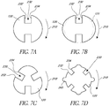
- the drill bit core 120 of the drill bit 100 can have different cross-sectional shapes.
- the cross-sectional shape of the drill bit core 120 can be configured to minimize cutting soft bone, minimize friction, minimize heat, and/or maximize directional control (e.g., avoid wobbling) or maximize cutting of hard bone.
- the direction of rotation of the drill bit core 120 is indicated by the arrow 210.
- Figure 7A shows a drill bit core 120 having a substantially rounded profile.
- the radial distance of the cutting edge 232 is substantially equal to the radial distance of the trailing edge 234.
- the drill bit core 120 has two cutting flutes 230 that are circumferentially spaced 180° apart from one another.
- Figure 7B shows an oval-shaped drill bit core 120 having two cutting flutes 230 that are circumferentially spaced 180° apart from one another, with the radial distance of the cutting edge 232 being substantially equal to the radial distance of the trailing edge 234.
- the ovality of the drill bit 120 can be small as indicated by the dashed core 121.
- Figure 7C shows a tri-oval drill bit core 120 having three cutting flutes 230 circumferentially spaced about 120° apart from an adjacent cutting flute 232.
- the radial distance of the cutting edge 232 is substantially equal to the radial distance of the trailing edge 234.
- Figure 7D depicts a cruciform drill bit core 120 having four cutting flutes 230 circumferentially spaced about 90° apart from an adjacent cutting flute 232.
- the radial distance of the cutting edge 232 is substantially equal to the radial distance of the trailing edge 234.
- the drill bit core 120 can include one or more protrusions 245.
- the protrusion 245 can extend radially beyond the radial distance of the cutting edge 232 by about 50 ⁇ m.
- the drill bit 100 can have a variety of macro-shapes.
- the macro-shape of the drill bit 100 can be defined by the outer dimension of the drill bit core 120 along the longitudinal axis 102 of the drill bit 100.
- the shape of the osteotomy will match the macro-shape of the drill bit 100 that was used to produce the osteotomy.
- the macro-shape of the drill bit 100 can be tapered in the apical direction.
- the taper can be pointed or blunted.
- the taper can be constant along the length of the drill bit 100.
- the taper can vary along the length of the drill bit 100. For example, the taper in some regions of the drill bit 100 may be steeper than in other regions of the drill bit 100.
- the macro-shape of the drill bit 100 is selected to match the macro-shape of the implant.
- the drill bit 100 can have an apical base 404 and a coronal base 406.
- the apical base 404 is the apical-most surface of an apical portion 414
- the coronal base 406 is the coronal-most surface of a coronal portion 416, as shown in Figure 8B .
- the coronal base 406 can have an outer dimension 405 that is greater than the outer dimension 403 of the apical base 404.
- the drill bit 100 can have a coronal base 406 that has an outer dimension 405 of about 3.2 mm wide and an apical base 404 that has an outer dimension 403 of about 2 mm wide.
- the coronal portion 416 can taper in the apical direction while the apical portion has a substantially constant width.
- the coronal portion 416 can have a longitudinal length 409 and the apical portion 414 can have a longitudinal length 407.
- the coronal portion 416 has a longitudinal length 409 of about 13 mm and the apical portion 414 has a longitudinal length 407 of about 2 mm.
- the drill bit 100 can have an intermediate portion 418 interposed between the coronal portion 416 and the apical portion 414.
- the drill bit 100 can have more than one intermediate portion 418, as shown in the embodiment on the far right of Figure 8A .
- the intermediate portion 418 can have a coronal surface 420 that is the coronal-most portion of the intermediate portion 418.
- the drill bit 100 can have a coronal base 406 that has a width of about 3.8 mm, a coronal surface 420 that is about 3.2 mm, and an apical base 404 that is about 2 mm.
- the longitudinal length of the coronal portion 416 can be about 12 mm
- the longitudinal length of the intermediate portion 418 can be about 1 mm
- the longitudinal length of the apical portion 414 can be about 2 mm.
- Figure 9 depicts a non-limiting, illustrative embodiment of the drill bit 100 having a twisted and tapered oval drill bit core 120, as described above.
- the cutting flute 230 can be adapted to transport cut bone out of the osteotomy.
- the cutting flute 230 has a spiral configuration at a pitch of about 45°. The pitch of the cutting flute 230 can be selected so that bone chips do not get stuck in the cutting flute 230 and are transported out of the osteotomy.
- the cutting flute 230 wraps in the direction of rotation of the drill bit 100, which is clockwise toward the apical end 104.
- the depicted embodiment has guide threads 113 with a round profile.
- the guide threads 113 can be substantially perpendicular to the longitudinal axis 102, as shown in Figure 9 .
- the guide threads 113 can be angled toward the apical end 104 of the drill bit 100.
- the pitch of the guide thread does not match the one of the implant. This has the advantage that the user does not have to be concerned about following the same thread path.
- Figure 10 depicts a schematic of an embodiment of a method of use of the drill bit 100 of an embodiment of the present disclosure to prepare an osteotomy for receiving an implant.
- the drill bit 100 can be adapted to reduce the number of tools and/or steps needed to prepare the osteotomy.
- the procedure of preparing an osteotomy for receiving an implant may be referred to herein as "normalizing" the bone.
- the drill bit 100 can be adapted to normalize the bone with the use of only one drill bit 100.
- two or more drill bits 100 can be used to normalize the bone.
- the method may include a step 600 in which a hole is drilled into the bone using a pilot drill bit that has a diameter smaller than the drill bit 100.
- the pilot step 600 uses a pilot drill bit having a diameter of 2 mm.
- the pilot step 600 can be performed using irrigation.
- the drill speed in step 600 can be about 800 rpm.
- the method of preparing the osteotomy for receiving an implant can include a normalizing step 602.
- a first drill bit 100 according to an embodiment described herein can be used in the normalizing step 602.
- the first drill bit 100 can be selected based on the implant that will be implanted into the osteotomy.
- the first drill bit 100 can be used to enlarge the hole created by a drilling step 600.
- the normalizing step 602 can be performed without performing a preceding drilling step 600.
- the normalizing step 602 can be performed with or without irrigation.
- the normalizing step 602 can be performed using a drill speed of about 50 to 100 rpm.
- the normalizing step 602 can include a measuring step 604 that determines the insertion torque.
- the measuring step 604 can determine the insertion torque by sensing the torque applied to the drill bit 100.
- the measuring step 604 can include an evaluating step 606 that evaluates whether the normalization of the bone is successful.
- the evaluating step 606 can compare an actual insertion torque as measured in the measuring step 604 with a desired insertion torque.
- the desired insertion torque can be determined by a look-up table that correlates implant success to insertion torque.
- the normalization can be adequate when the insertion torque is less than or equal to about 40 Ncm.
- the desired insertion torque may be modified based on the type of implant that is intended to be installed in the osteotomy.
- the method of preparing the osteotomy for receiving an implant can include a further normalizing step 608.
- the further normalizing step 608 can be performed using a second drill bit 100' according to an embodiment described herein.
- the second drill bit 100' can have a different macro-shape compared to the first drill bit 100.
- the second drill bit 100' can have a different configuration of the drill bit core 120 compared to the first drill bit 100.
- the method of preparing the osteotomy for receiving an implant can be iterative. For example, the method can proceed from the further normalization step 608 to the measuring step 604 and the evaluating step 606 multiple times until the normalization is adequate to receive an implant.
- the torque is measured, by a drilling unit or controller connected to the drill bit 100, at or until a predefined length of the drill bit 100 has been inserted into the hole created by a drilling step 600.
- Said predefined length can be controlled mechanically, for example, the drill bit can have a removable stop whose position is calibrated for soft bone indicating the maximum drilling length for the torque measurement.
- the predefined length can be controlled by a software of the drill unit measuring the torque. If the torque measureduntil or at said predefined length is above a certain value indicating the presence of hard bone, then the drill unit can indicate to the user to continue drilling beyond the predefined length.
- the removable stop can be removed and drilling resumes until a second fixed stop, whose position is calibrated for hard bone. If the torque measured until or at said predefined length is below a certain value indicating the presence of soft bone the drill unit can indicate to the user to stop drilling and to start implanting an implant 620. Furthermore the drill unit can be provided with a screen or any kind of user interface indicating to the user the quality of the bone to help the decision. The type of bone can also be indicated by the drilling unit to the user using and audible signal such as an alarm. Alternatively the drilling unit can directly control the insertion depth based on the torque measured and stop the drilling with first drill bit 100 after a specified number of turns.
- the drill bit 100 of the present disclosure can be used in a method of implanting an implant into a jaw bone 30 (shown in Figure 1 ).
- the method of implanting an implant into a jaw bone 30 can include the method of preparing the osteotomy for receiving an implant described above.
- the method of implanting an implant into a jaw bone 30 can include an installing step 610.
- the installing step 610 can include implanting an implant 620 into an osteotomy prepared with the drill bit 100.
- the installing step can be performed with or without irrigation.
- the installing step 610 can be performed at a rotational speed of the implant 620 of about 50 rpm. In some variants, the installing step 610 can be performed at a rotational speed of the implant 620 of about 25 rpm.
- FIG 11 is a schematic representation of another embodiment of a method of use of the drill bit 100 of an embodiment of the present disclosure to prepare an osteotomy for receiving an implant.
- the method may include a pilot step 700 in which a hole is drilled into the jaw bone 730 using a pilot drill bit that has a diameter smaller than the drill bit 100.
- the hole created in the pilot step 700 serves as a guiding hole for the following steps.
- the hole created in the pilot step 700 may be an underprepared site.
- the pilot step 700 can be performed using irrigation.
- the drill speed in the pilot step 700 can be about 800 rpm.
- the pilot drill bit used in the pilot step 700 may have a diameter in the range of 1.8 to 2.4 mm.
- the pilot step 700 uses a pilot drill bit having a diameter of 2 mm.
- the method of preparing the osteotomy for receiving an implant can include a first normalizing step 702.
- a first drill bit 100 according to an embodiment described herein can be used in the first normalizing step 702.
- the first drill bit 100 can be selected based on the implant that will be implanted into the osteotomy.
- the first drill bit 100 can be used to enlarge the hole created by the pilot step 700.
- the first normalizing step 702 can be carried out without performing a preceding drilling step 700.
- the first normalizing step 702 can be performed with or without irrigation.
- the first normalizing step 702 can be performed using a drill speed of about 50 to 100 rpm, in particular, using a drill speed of about 50 rpm.
- the first drill bit 100 may be configured such that the first cutting edge is a first radial distance from the longitudinal axis and a maximum outer dimension of the drill bit core is a second radial distance from the longitudinal axis, wherein the second radial distance is larger than the first radial distance.
- the drill bit core of the first drill bit 100 may have a no-cutting zone defined as the difference between the second radial distance and the first radial distance.
- the method illustrated in Figure 11 may comprise a first evaluating step 704 in which it is evaluated whether the first drill bit 100 can be fully inserted into the osteotomy in the first normalizing step 702.
- this first evaluating step 704 it is determined whether the first drill bit 100 is properly inserted into the osteotomy, i.e., inserted along a sufficient length of the first drill bit 100, and the torque applied to the first drill bit 100 is measured. Based on the results of this evaluation, i.e., on the results of determining the insertion length or depth and of measuring the applied torque, the next steps are selected, as will be further detailed in the following.
- the first drill bit 100 may be provided with a marking, such as a shoulder, which indicates an insertion length of the first drill bit 100 that is equal or at least similar to the length of the implant 720 to be implanted into the osteotomy. If it is found that, in the first normalizing step 702, the first drill bit 100 has been inserted into the osteotomy along such a length that the marking is arranged at the coronal end of the osteotomy, it is determined that the first drill bit 100 is inserted along a sufficient length.
- a marking such as a shoulder
- the torque applied to the first drill bit 100 can be measured, for example, by a drilling unit or a controller connected to the first drill bit 100, e.g., when or until a predefined length of the first drill bit 100 has been inserted into the hole created in the pilot step 700.
- the first evaluating step 704 can compare an actual insertion torque as measured in this step with a desired insertion torque.
- the desired insertion torque can be determined by a look-up table that correlates implant success to insertion torque.
- the normalization can be adequate when the insertion torque is less than or equal to about 40 Ncm.
- the desired insertion torque may be modified based on the type of implant that is intended to be installed in the osteotomy.
- an installing step 706 is performed.
- the implant 720 is inserted into the osteotomy prepared with the drill bit 100.
- the installing step 706 can be performed with or without irrigation.
- the installing step 706 can be performed at a rotational speed of the implant 720 of about 50 rpm. In some variants, the installing step 706 can be performed at a rotational speed of the implant 720 of about 25 rpm.
- the implant 720 may be inserted into the jaw bone 730 under the application of an insertion torque in the range of about 25 to 70 Ncm (see Figure 11 ).
- a second normalizing step 708 is performed.
- the second normalizing step 708 can be performed using a second drill bit 100' according to an embodiment described herein.
- the second drill bit 100' can have a different macro-shape compared to the first drill bit 100.
- the second drill bit 100' can have a different configuration of the drill bit core 120 compared to the first drill bit 100.
- the second drill bit 100' may be configured such that the first cutting edge is arranged at a maximum of the non-round or non-circular portion of the drill bit core or arranged so as to be circumferentially spaced from a maximum of the non-round or non-circular portion of the drill bit core in a direction which is opposite to the rotation direction in which the second drill bit 100' is rotated when inserting it into the osteotomy.
- the second drill bit 100' may be configured such that the first cutting edge is disposed outside the first compression zone of the drill bit core.
- the method of preparing the osteotomy for receiving an implant can be iterative. For example, the method can proceed from a further normalization step, e.g., the second normalizing step 708, to an evaluating step, which may be performed in substantially the same or a similar manner as the first evaluating step 704, multiple times until the normalization is adequate to receive the implant 720.
- a further normalization step e.g., the second normalizing step 708
- an evaluating step which may be performed in substantially the same or a similar manner as the first evaluating step 704
- the second normalizing step 708 may be followed by a second evaluating step 710 in which it is evaluated whether the second drill bit 100' can be fully inserted into the osteotomy in the second normalizing step 708.
- the second evaluating step 710 can be performed in substantially the same manner as detailed above for the first evaluating step 704.
- an installing step 712 is performed.
- the implant 720 is inserted into the osteotomy prepared with the drill bit 100', e.g., in the same manner as detailed above for the installing step 706.
- the implant 720 may be inserted into the jaw bone 730 under the application of an insertion torque in the range of about 35 to 70 Ncm (see Figure 11 ).
- a drilling step 714 is performed.
- the drilling step 714 can be performed using a drill bit that has a diameter larger than that of the pilot drill bit used in the pilot step 700.
- the drill bit used in the drilling step 714 may have a diameter in the range of 3.4 to 3.9 mm.
- the drill bit used in the drilling step 714 may be a dense bone drill bit.
- the drilling step 714 can be performed using irrigation.
- the drill speed in the drilling step 714 can be about 800 rpm.
- the drilling step 714 may be followed by another evaluating step (not shown in Figure 11 ). This further evaluating step may be performed in substantially the same manner as detailed above for the first evaluating step 704.
- an installing step 716 may be performed.
- the implant 720 is inserted into the osteotomy prepared in the drilling step 714, e.g., in the same manner as detailed above for the installing step 706.
- the implant 720 may be inserted into the jaw bone 730 under the application of an insertion torque in the range of about 35 to 70 Ncm (see Figure 11 ).
- the threshold of the torque applied to the first drill bit 100 and the second drill bit 100', respectively, is chosen such that it is smaller than the torque threshold of the implant 720.
- the implant 620 used in the above mentioned methods can be an implant as described in the International Patent Application PCT/EP2017/051953 entitled "Dental Implant, Insertion Tool for Dental Implant and Combination of Dental Implant and Insertion Tool", under Attorney Docket No.P1542PC00, and filed on the same day as the present application by the Applicant, Nobel Biocare Services AG, in particular the embodiments of Figures 1 , 2 , 10-12 ,13-15, 20 and 21, 34 and 35 and related paragraphs of said application.
- Said implant can be a dental implant, comprising: a core body having an apical end, a coronal end, and an outer surface extending along a longitudinal direction between said apical end and said coronal end; and
- Said implant can also have a second core shaped zone, in which second core shaped zone the cross-section of said core body has a number of main directions in which the radius measuring the distance between the center of the cross section and its outer contour takes a relative maximum value and thus a higher value than in neighbouring orientations, and wherein in said first core shaped zone a core eccentricity parameter defined as the ratio of the maximum radius of the cross section of said core body to its minimum radius is larger than in said second core shaped zone.
- Such an implant can also comprise at least one thread extending outwardly from said core body, said thread defining a thread outer volume, wherein said thread comprises
- the implant can also comprise a second thread shaped zone in which second thread shaped zone the outer cross-section of said thread outer volume has a number of main directions in which the radius measuring the distance between the center of the cross section and its outer contour takes a relative maximum value and thus a higher value than in neighboring orientations, wherein in said first thread shaped zone a core eccentricity parameter defined as the ratio of the maximum radius of the outer cross section of said thread outer volume to its minimum radius is larger than in said second core shaped zone.
- Such an implant can also have a number of cutting flutes provided at least in said transition zone.
- the dental implant in particular for insertion into bone tissue of a patient, can also comprise:
- the invention also concerns a kit of parts comprising and a drill bit as above defined and an implant, and in particular an implant as above defined.
- certain embodiments and methods described above are in the context of dental surgery and forming a hole in a patient's jawbone to receive a dental implant; however, it should be appreciated that certain features and aspects of the embodiments described herein can also find utility in other surgical applications.
- certain features and aspects of the embodiments described herein may be used in a drill configured to form a hole in another portion of the body (e.g., bones of the leg, spine, and/or arm) and/or a hole configured to receive a different type of device (e.g., a rod, a spacer, etc.)
- Numerical data may be expressed or presented herein in a range format. It is to be understood that such a range format is used merely for convenience and brevity and thus should be interpreted flexibly to include not only the numerical values explicitly recited as the limits of the range, but also interpreted to include all of the individual numerical values or sub-ranges encompassed within that range as if each numerical value and sub-range is explicitly recited. As an illustration, a numerical range of "about 1 to 5" should be interpreted to include not only the explicitly recited values of about 1 to about 5, but should also be interpreted to also include individual values and sub-ranges within the indicated range.
Claims (14)
- Foret comprenant :une extrémité apicale, une extrémité coronale et un axe longitudinal s'étendant entre l'extrémité apicale et l'extrémité coronale ;un noyau de foret entourant circonférentiellement l'axe longitudinal ;un premier bord coupant ; etun fil de guidage qui s'étend radialement vers l'extérieur à partir du noyau de foret dans lequel le premier bord coupant est à une première distance radiale de l'axe longitudinal et une dimension externe maximale du noyau de foret est à une seconde distance radiale de l'axe longitudinal, la seconde distance radiale étant plus grande que la première distance radiale.
- Foret selon l'une quelconque des revendications précédentes, dans lequel le noyau de foret se rétrécit vers l'extrémité apicale.
- Foret selon l'une quelconque des revendications précédentes, dans lequel le noyau de foret comprend une dimension externe maximale qui se déplace circonférentiellement autour de l'axe longitudinal lorsque le noyau de foret s'étend vers l'extrémité apicale.
- Foret de forage selon l'une quelconque des revendications précédentes, dans lequel le noyau a un profil non arrondi et dans lequel le profil non arrondi est trilobé.
- Foret de forage selon l'une quelconque des revendications précédentes, dans lequel le fil de guidage a un profil sensiblement rond.
- Foret de forage selon l'une quelconque des revendications précédentes, dans lequel le noyau de foret comprend en outre une cannelure de coupe.
- Foret selon la revendication 6, dans lequel la cannelure de coupe s'enroule circonférentiellement autour de l'axe longitudinal lorsque la cannelure de coupe s'étend entre l'extrémité apicale et l'extrémité coronale du foret.
- Foret selon l'une quelconque des revendications précédentes, dans lequel le premier bord coupant est à une première distance radiale de l'axe longitudinal et une dimension externe maximale du noyau de foret est à une seconde distance radiale de l'axe longitudinal, le noyau de foret ayant une zone sans coupe définie comme la différence entre la seconde distance radiale et la première distance radiale.
- Foret selon la revendication 8, dans lequel la zone sans coupe reste constante entre les extrémités apicale et coronale du foret.
- Foret selon l'une quelconque des revendications précédentes, dans lequel le fil de guidage a une hauteur définie comme une distance sur laquelle le fil de guidage s'étend radialement à l'écart du noyau de foret et dans lequel la hauteur du fil de guidage est comprise entre 0 et 1 000 µm, de préférence entre 0 et 500 µm et plus préférablement entre 50 et 250 µm.
- Foret selon l'une quelconque des revendications précédentes, dans lequel le fil de guidage a une largeur de 250 µm ou moins, de préférence de 200 µm ou moins et plus préférablement de 150 µm ou moins.
- Foret selon l'une quelconque des revendications 6 à 10, dans lequel un pas du fil de guidage est différent d'un pas de la cannelure de coupe.
- Kit de pièces comprenant un foret selon l'une quelconque des revendications précédentes et un implant, en particulier un implant dentaire.
- Kit de pièces selon la revendication 13, dans lequel l'implant comprend un fil, le foret comprend un fil de guidage qui s'étend radialement vers l'extérieur depuis le noyau de foret, et le fil de guidage diffère du fil de l'implant en termes de pas et/ou de taille et/ou de largeur.
Priority Applications (1)
| Application Number | Priority Date | Filing Date | Title |
|---|---|---|---|
| EP21213914.1A EP4056143A1 (fr) | 2016-01-29 | 2017-01-30 | Outil de dentisterie |
Applications Claiming Priority (3)
| Application Number | Priority Date | Filing Date | Title |
|---|---|---|---|
| EP16153496 | 2016-01-29 | ||
| EP17701733.2A EP3407823B1 (fr) | 2016-01-29 | 2017-01-30 | Outil de dentisterie |
| PCT/EP2017/051956 WO2017129828A1 (fr) | 2016-01-29 | 2017-01-30 | Outil de dentisterie |
Related Parent Applications (1)
| Application Number | Title | Priority Date | Filing Date |
|---|---|---|---|
| EP17701733.2A Division EP3407823B1 (fr) | 2016-01-29 | 2017-01-30 | Outil de dentisterie |
Related Child Applications (1)
| Application Number | Title | Priority Date | Filing Date |
|---|---|---|---|
| EP21213914.1A Division EP4056143A1 (fr) | 2016-01-29 | 2017-01-30 | Outil de dentisterie |
Publications (2)
| Publication Number | Publication Date |
|---|---|
| EP3593751A1 EP3593751A1 (fr) | 2020-01-15 |
| EP3593751B1 true EP3593751B1 (fr) | 2021-12-15 |
Family
ID=55272368
Family Applications (3)
| Application Number | Title | Priority Date | Filing Date |
|---|---|---|---|
| EP21213914.1A Pending EP4056143A1 (fr) | 2016-01-29 | 2017-01-30 | Outil de dentisterie |
| EP17701733.2A Active EP3407823B1 (fr) | 2016-01-29 | 2017-01-30 | Outil de dentisterie |
| EP19186061.8A Active EP3593751B1 (fr) | 2016-01-29 | 2017-01-30 | Outil de dentisterie |
Family Applications Before (2)
| Application Number | Title | Priority Date | Filing Date |
|---|---|---|---|
| EP21213914.1A Pending EP4056143A1 (fr) | 2016-01-29 | 2017-01-30 | Outil de dentisterie |
| EP17701733.2A Active EP3407823B1 (fr) | 2016-01-29 | 2017-01-30 | Outil de dentisterie |
Country Status (14)
| Country | Link |
|---|---|
| US (2) | US11045287B2 (fr) |
| EP (3) | EP4056143A1 (fr) |
| JP (1) | JP6701342B2 (fr) |
| KR (2) | KR101938287B1 (fr) |
| CN (2) | CN113069226A (fr) |
| AU (2) | AU2017213176B2 (fr) |
| BR (1) | BR112018015403B1 (fr) |
| CA (3) | CA3048753C (fr) |
| ES (2) | ES2747829T3 (fr) |
| IL (1) | IL260277B (fr) |
| PL (1) | PL3407823T3 (fr) |
| RU (1) | RU2695004C1 (fr) |
| WO (1) | WO2017129828A1 (fr) |
| ZA (1) | ZA201803925B (fr) |
Families Citing this family (8)
| Publication number | Priority date | Publication date | Assignee | Title |
|---|---|---|---|---|
| WO2017129828A1 (fr) * | 2016-01-29 | 2017-08-03 | Nobel Biocare Services Ag | Outil de dentisterie |
| US11246606B2 (en) * | 2019-08-12 | 2022-02-15 | Biomet 3I, Llc | Drill bit |
| US20210205053A1 (en) * | 2020-01-07 | 2021-07-08 | Joel L. Rosenlicht | Implant dentistry methods and apparatuses |
| US11529147B2 (en) * | 2020-08-07 | 2022-12-20 | Mighty Oak Medical, Inc. | Drilling depth and control apparatus and methods for using the same |
| RU2758244C1 (ru) * | 2020-09-28 | 2021-10-27 | Патрик Паглавян | Хирургический набор инструментов для зубной имплантации |
| WO2023083984A1 (fr) * | 2021-11-13 | 2023-05-19 | Nobel Biocare Services Ag | Mèche de forage |
| KR102425210B1 (ko) * | 2021-11-18 | 2022-07-27 | (주) 대성다이아몬드툴 | 테이퍼 드릴 리머의 제조 방법 및 이에 의해 제조된 테이퍼 드릴 리머 |
| WO2023164094A1 (fr) * | 2022-02-25 | 2023-08-31 | Life Spine, Inc. | Vis sans fin à disque vertébral |
Citations (1)
| Publication number | Priority date | Publication date | Assignee | Title |
|---|---|---|---|---|
| US6217267B1 (en) * | 1997-07-16 | 2001-04-17 | Osg Corporation | Cold forming tap having internal finish cutting edge and method of producing the same |
Family Cites Families (75)
| Publication number | Priority date | Publication date | Assignee | Title |
|---|---|---|---|---|
| CH410276A (de) | 1963-01-07 | 1966-03-31 | Straumann Inst Ag | Instrument zum Verbinden mindestens zweier Bruchstücke von Röhrenknochen |
| JPS5621505U (fr) * | 1979-07-27 | 1981-02-25 | ||
| JPS6040328B2 (ja) | 1981-01-21 | 1985-09-10 | オ−エスジ−株式会社 | 切削工具 |
| DE3233968A1 (de) | 1982-09-14 | 1984-03-15 | Hartmetallwerkzeugfabrik Andreas Maier GmbH + Co KG, 7959 Schwendi | Mehrlippenbohrer |
| DE3544433C2 (de) | 1985-12-16 | 1995-12-14 | Hilti Ag | Gesteinsbohrer |
| IT1218548B (it) | 1987-12-04 | 1990-04-19 | Pier Luigi Mondani | Perno autofilettante per l'impianto di protesi dentali |
| US5007835A (en) * | 1989-08-17 | 1991-04-16 | Maurice Valen | Dental implant |
| US5261818A (en) | 1992-07-13 | 1993-11-16 | Leon Shaw | Multi-fluted dental irrigation drill |
| DE9215541U1 (fr) | 1992-11-14 | 1993-01-28 | Krupp Medizintechnik Gmbh, 4300 Essen, De | |
| US5437675A (en) | 1993-06-11 | 1995-08-01 | Wilson; Franklin D. | Polygonal bone punch |
| JPH11510103A (ja) | 1995-07-27 | 1999-09-07 | ラルフ・シー・メイズ | ドリルビット |
| ATE218047T1 (de) | 1995-12-11 | 2002-06-15 | Ormco Corp | Endodontisches instrument |
| WO1998003119A1 (fr) | 1996-07-18 | 1998-01-29 | Implant Innovations, Inc. | Outils d'osteotome motorises de tassement des tissus osseux |
| US5857995A (en) * | 1996-08-15 | 1999-01-12 | Surgical Dynamics, Inc. | Multiple bladed surgical cutting device removably connected to a rotary drive element |
| UA18573C2 (uk) | 1996-09-17 | 1997-12-25 | Казбек Олександрович Гогаєв | Зубhа розгортка |
| JP3309064B2 (ja) | 1997-07-03 | 2002-07-29 | 株式会社彌満和製作所 | 下穴さらい刃および雌ねじ内径さらい刃を具える盛上げタップ |
| DE19732983B4 (de) | 1997-07-31 | 2005-02-17 | Friadent Gmbh | Instrument zur Knochenaufweitung |
| DE19823720C1 (de) | 1998-05-27 | 1999-10-21 | Brasseler Gmbh & Co Kg Geb | Dentalbohrer |
| US6135208A (en) | 1998-05-28 | 2000-10-24 | Halliburton Energy Services, Inc. | Expandable wellbore junction |
| US6514258B1 (en) * | 1998-11-04 | 2003-02-04 | Implant Innovations, Inc. | Penetration limiting stop elements for a drill bit used for bone tissue |
| US6042376A (en) | 1999-03-01 | 2000-03-28 | Essential Dental Systems, Inc. | Non-circular endodontic instruments |
| PL195558B1 (pl) * | 1999-06-03 | 2007-10-31 | Arsline Sa | Urządzenie zabezpieczające do obrotowego przyrządu wiercącego, stosowanego między innymi w chirurgii dentystycznej, oraz sposób wstępnego kalibrowania i zachowywania głębokości wiercenia za pomocą tego urządzenia |
| AT407826B (de) | 2000-02-25 | 2001-06-25 | Jesch Wolfgang Dr | Vorrichtung mit einem knochenfräser |
| ES2325478T3 (es) | 2000-05-11 | 2009-09-07 | Nobel Biocare Ab | Pseudograbado de una herramienta dental de preparacion para la osteotomia recubierta de carbono similar al diamante. |
| US6734858B2 (en) | 2000-12-27 | 2004-05-11 | Avon Products, Inc. | Method and apparatus for use of computer aging to demonstrate a product benefit |
| JP4269302B2 (ja) * | 2001-02-28 | 2009-05-27 | マニー株式会社 | 歯科用リーマ |
| FI110575B (fi) | 2001-05-16 | 2003-02-28 | Inion Ltd | Työkalu kierteytettyjen kirurgisten reikien tekemiseksi |
| SE519067C2 (sv) * | 2001-05-22 | 2003-01-07 | Sandvik Ab | Gängtapp med lobformat tvärsnitt och gängslappningsparti |
| US6966774B2 (en) | 2001-08-16 | 2005-11-22 | Cloudland Institute, Llc. | Endodontic instrument having notched cutting surfaces |
| US6761697B2 (en) | 2001-10-01 | 2004-07-13 | L'oreal Sa | Methods and systems for predicting and/or tracking changes in external body conditions |
| JP3960589B2 (ja) | 2002-01-28 | 2007-08-15 | 有限会社新城製作所 | スチールハウス用ドリルねじ |
| DE60332095D1 (de) | 2002-02-27 | 2010-05-27 | Arsline Sa | Instrument zur vorbereitung von knochenmaterial, verwendbar insbesondere in der zahntechnik und vorrichtung zu seiner verwendung |
| US7147469B2 (en) | 2002-08-28 | 2006-12-12 | Ormco Corporation | Endodontic instrument |
| US20040191723A1 (en) | 2003-03-31 | 2004-09-30 | Shearer Dane L. | Endodontic instrument |
| US7094056B2 (en) | 2003-05-01 | 2006-08-22 | Scianamblo Michael J | Endodontic instrument having reversed helix |
| US7955078B2 (en) | 2003-05-01 | 2011-06-07 | Scianamblo Michael J | Endodontic instruments for preparing endodontic cavity spaces |
| WO2005065565A1 (fr) | 2003-12-31 | 2005-07-21 | Palomar Medical Technologies, Inc. | Traitement dermatologique avec visualisation |
| US7967605B2 (en) | 2004-03-16 | 2011-06-28 | Guidance Endodontics, Llc | Endodontic files and obturator devices and methods of manufacturing same |
| DE102004047909A1 (de) * | 2004-09-29 | 2006-04-13 | Bredent Dentalgeräte u. Materialien Fach- u. Organisationsberatung Peter Brehm | Bohrer für medizinische und zahnmedizinische Zwecke |
| WO2006043702A1 (fr) | 2004-10-22 | 2006-04-27 | Shiseido Company, Ltd. | Système de diagnostic de l’état de la peau et système de conseil cosmétique |
| DE102004059264B4 (de) * | 2004-12-08 | 2007-02-22 | EMUGE-Werk Richard Glimpel GmbH & Co. KG Fabrik für Präzisionswerkzeuge | Werkzeug und Verfahren zur Erzeugung eines Gewindes in einem Werkstück |
| ES2363981T3 (es) | 2005-04-08 | 2011-08-22 | Michael J. Scianamblo | Instrumentos endodónticos plegables. |
| US7300281B2 (en) | 2005-08-02 | 2007-11-27 | Giuseppe Cantatore | Endodontic file having bi-directional scraping edges |
| US7766657B2 (en) | 2005-08-09 | 2010-08-03 | Andris Jaunberzins | Endodontic file combining active and passive cutting edges |
| US20070101827A1 (en) | 2005-11-01 | 2007-05-10 | Quan Nancy N | Endodontic Instrument |
| US7357606B1 (en) | 2006-02-03 | 2008-04-15 | United States Of America As Represented By The Administrator Of The National Aeronautics And Space Administration | Self-advancing step-tap tool |
| JP2007292131A (ja) | 2006-04-21 | 2007-11-08 | Nitto Seiko Co Ltd | 雌ねじ成形機能付きねじ |
| US20080080951A1 (en) | 2006-09-07 | 2008-04-03 | Teng-Hung Lin | Screw with a drilling tail |
| US7806693B2 (en) | 2007-04-23 | 2010-10-05 | Nobel Biocare Services Ag | Dental implant |
| KR100930911B1 (ko) * | 2007-11-22 | 2009-12-10 | 오스템임플란트 주식회사 | 다단구조를 이용한 치과용 임플란트 드릴 |
| US20090220914A1 (en) * | 2008-02-28 | 2009-09-03 | Dental- Li Uri Consulting 2007 Ltd. | Dental implant and a method of implantation thereof |
| KR100969500B1 (ko) * | 2008-09-03 | 2010-07-14 | 주식회사 제일메디칼코퍼레이션 | 임플란트 시스템의 모터제어방법 및 이를 이용한 장치 |
| DE102009029714A1 (de) * | 2009-06-16 | 2010-12-30 | Dentaurum J.P. Winkelstroeter Kg | Chirurgischer Bohrer |
| JP5685593B2 (ja) | 2009-08-26 | 2015-03-18 | ストライカー・アイルランド・リミテッド | リブ付き外科用バー |
| ES2710179T3 (es) | 2009-09-07 | 2019-04-23 | Nobel Biocare Services Ag | Conjunto de implantación |
| ES2596828T3 (es) * | 2009-09-07 | 2017-01-12 | Nobel Biocare Services Ag | Componentes para el roscado guiado de un hueso |
| JP5362854B2 (ja) * | 2010-01-13 | 2013-12-11 | オーエスジー株式会社 | 内径仕上げ刃付き盛上げタップ |
| CA2787116C (fr) | 2010-01-14 | 2015-08-25 | Osstemimplant Co., Ltd. | Foret pour chirurgie implantaire |
| CN201631404U (zh) * | 2010-03-05 | 2010-11-17 | 郑昌财 | 植牙钻头 |
| EP2460489A1 (fr) * | 2010-12-03 | 2012-06-06 | Maillefer Instruments Holding S.À.R.L. | Instrument pour l'alésage des canaux radiculaires dentaires |
| CN103097062B (zh) | 2011-01-31 | 2014-11-05 | 京瓷株式会社 | 钻头及使用该钻头的切削加工物的制造方法 |
| US9022783B2 (en) | 2011-03-23 | 2015-05-05 | Huwais IP Holding LLC | Fluted osteotome and surgical method for use |
| US10039621B2 (en) | 2011-03-23 | 2018-08-07 | Huwais IP Holding LLC | Autografting osteotome |
| US9028253B2 (en) * | 2011-03-23 | 2015-05-12 | Huwais IP Holding LLC | Fluted osteotome and surgical method for use |
| US9326778B2 (en) | 2011-03-23 | 2016-05-03 | Huwais IP Holding LLC | Autografting osteotome |
| KR102085066B1 (ko) * | 2011-06-02 | 2020-03-05 | 엠아이에스 임플란츠 테크놀러지스 리미티드 | 치과용 임플란트 |
| KR101205841B1 (ko) * | 2011-09-22 | 2012-11-28 | 오스템임플란트 주식회사 | 치과용 드릴, 드릴셋트 및 치조골의 천공방법 |
| AU2013345341B2 (en) * | 2012-11-19 | 2017-12-07 | Huwais IP Holding LLC | Autografting osteotome |
| KR20150088280A (ko) | 2012-11-19 | 2015-07-31 | 산드빅 인터렉츄얼 프로퍼티 에이비 | 골질의 수술전 평가를 위한 드릴과 탭 및 방법 |
| WO2014083614A1 (fr) * | 2012-11-27 | 2014-06-05 | 日東精工株式会社 | Vis pour implant |
| CA2922053A1 (fr) | 2013-08-21 | 2015-02-26 | Michael J. Scianamblo | Outils de fraisage dentaire et osseux a mouvement de precession, et appareil de prelevement de tissu osseux |
| FR3013582B1 (fr) * | 2013-11-25 | 2016-01-22 | Biotech Dental | Outil dentaire a bandes indicatrices de penetration |
| CN204121189U (zh) * | 2014-10-10 | 2015-01-28 | 上海新世纪齿科材料有限公司 | 一种口腔种植体 |
| CA2970323C (fr) * | 2014-12-09 | 2022-03-29 | Biomet 3I, Llc | Dispositif robotique pour chirurgie dentaire |
| WO2017129828A1 (fr) | 2016-01-29 | 2017-08-03 | Nobel Biocare Services Ag | Outil de dentisterie |
-
2017
- 2017-01-30 WO PCT/EP2017/051956 patent/WO2017129828A1/fr active Application Filing
- 2017-01-30 EP EP21213914.1A patent/EP4056143A1/fr active Pending
- 2017-01-30 CN CN202110293427.5A patent/CN113069226A/zh active Pending
- 2017-01-30 CA CA3048753A patent/CA3048753C/fr active Active
- 2017-01-30 JP JP2018530897A patent/JP6701342B2/ja active Active
- 2017-01-30 KR KR1020187017483A patent/KR101938287B1/ko active IP Right Grant
- 2017-01-30 KR KR1020197000594A patent/KR102451445B1/ko active IP Right Grant
- 2017-01-30 EP EP17701733.2A patent/EP3407823B1/fr active Active
- 2017-01-30 US US16/073,281 patent/US11045287B2/en active Active
- 2017-01-30 AU AU2017213176A patent/AU2017213176B2/en active Active
- 2017-01-30 EP EP19186061.8A patent/EP3593751B1/fr active Active
- 2017-01-30 ES ES17701733T patent/ES2747829T3/es active Active
- 2017-01-30 CA CA3013241A patent/CA3013241C/fr active Active
- 2017-01-30 PL PL17701733T patent/PL3407823T3/pl unknown
- 2017-01-30 BR BR112018015403-2A patent/BR112018015403B1/pt active IP Right Grant
- 2017-01-30 RU RU2018129862A patent/RU2695004C1/ru active
- 2017-01-30 CA CA3135631A patent/CA3135631A1/fr active Pending
- 2017-01-30 CN CN201780004828.6A patent/CN108366843B/zh active Active
- 2017-01-30 ES ES19186061T patent/ES2905457T3/es active Active
-
2018
- 2018-06-12 ZA ZA2018/03925A patent/ZA201803925B/en unknown
- 2018-06-26 IL IL260277A patent/IL260277B/en active IP Right Grant
-
2019
- 2019-01-03 AU AU2019200021A patent/AU2019200021B2/en active Active
-
2021
- 2021-04-30 US US17/245,503 patent/US11857391B2/en active Active
Patent Citations (1)
| Publication number | Priority date | Publication date | Assignee | Title |
|---|---|---|---|---|
| US6217267B1 (en) * | 1997-07-16 | 2001-04-17 | Osg Corporation | Cold forming tap having internal finish cutting edge and method of producing the same |
Also Published As
Similar Documents
| Publication | Publication Date | Title |
|---|---|---|
| US11857391B2 (en) | Dentistry tool | |
| EP2391298B1 (fr) | Implant auto-taraudant | |
| EP3210548A1 (fr) | Fraise chirurgicale à cannelures non-appairées | |
| JP2005518867A (ja) | セルフドリリングインプラント | |
| WO2009066935A1 (fr) | Foret pour implant dentaire ayant une structure multicouche | |
| US20070083206A1 (en) | Self drilling and tapping bone screw | |
| JP2022504533A (ja) | 歯科インプラントねじ | |
| CN114072079A (zh) | 中空点压实工具 | |
| EP2836134A1 (fr) | Trépans chirurgicaux | |
| JP2019510577A (ja) | 骨組織に非円形空洞を形成する工具及び方法、ならびに前記工具を含むキット | |
| RU2794293C2 (ru) | Стоматологический инструмент | |
| EP3600128B1 (fr) | Instrument parabolique |
Legal Events
| Date | Code | Title | Description |
|---|---|---|---|
| PUAI | Public reference made under article 153(3) epc to a published international application that has entered the european phase |
Free format text: ORIGINAL CODE: 0009012 |
|
| STAA | Information on the status of an ep patent application or granted ep patent |
Free format text: STATUS: THE APPLICATION HAS BEEN PUBLISHED |
|
| AC | Divisional application: reference to earlier application |
Ref document number: 3407823 Country of ref document: EP Kind code of ref document: P |
|
| AK | Designated contracting states |
Kind code of ref document: A1 Designated state(s): AL AT BE BG CH CY CZ DE DK EE ES FI FR GB GR HR HU IE IS IT LI LT LU LV MC MK MT NL NO PL PT RO RS SE SI SK SM TR |
|
| STAA | Information on the status of an ep patent application or granted ep patent |
Free format text: STATUS: REQUEST FOR EXAMINATION WAS MADE |
|
| 17P | Request for examination filed |
Effective date: 20200715 |
|
| RBV | Designated contracting states (corrected) |
Designated state(s): AL AT BE BG CH CY CZ DE DK EE ES FI FR GB GR HR HU IE IS IT LI LT LU LV MC MK MT NL NO PL PT RO RS SE SI SK SM TR |
|
| STAA | Information on the status of an ep patent application or granted ep patent |
Free format text: STATUS: EXAMINATION IS IN PROGRESS |
|
| 17Q | First examination report despatched |
Effective date: 20201105 |
|
| GRAP | Despatch of communication of intention to grant a patent |
Free format text: ORIGINAL CODE: EPIDOSNIGR1 |
|
| STAA | Information on the status of an ep patent application or granted ep patent |
Free format text: STATUS: GRANT OF PATENT IS INTENDED |
|
| INTG | Intention to grant announced |
Effective date: 20210709 |
|
| RIN1 | Information on inventor provided before grant (corrected) |
Inventor name: BURKE, EDMUND Inventor name: GEISELHOERINGER, HANS Inventor name: HOLST, STEFAN Inventor name: SOLLBERGER, DAVID Inventor name: NUSSBAUMER, SILVIO Inventor name: QUARRY, ANTONY Inventor name: WEITZEL, JOERG |
|
| GRAS | Grant fee paid |
Free format text: ORIGINAL CODE: EPIDOSNIGR3 |
|
| GRAA | (expected) grant |
Free format text: ORIGINAL CODE: 0009210 |
|
| STAA | Information on the status of an ep patent application or granted ep patent |
Free format text: STATUS: THE PATENT HAS BEEN GRANTED |
|
| AC | Divisional application: reference to earlier application |
Ref document number: 3407823 Country of ref document: EP Kind code of ref document: P |
|
| AK | Designated contracting states |
Kind code of ref document: B1 Designated state(s): AL AT BE BG CH CY CZ DE DK EE ES FI FR GB GR HR HU IE IS IT LI LT LU LV MC MK MT NL NO PL PT RO RS SE SI SK SM TR |
|
| REG | Reference to a national code |
Ref country code: GB Ref legal event code: FG4D Ref country code: CH Ref legal event code: EP |
|
| REG | Reference to a national code |
Ref country code: IE Ref legal event code: FG4D Ref country code: DE Ref legal event code: R096 Ref document number: 602017051138 Country of ref document: DE |
|
| REG | Reference to a national code |
Ref country code: AT Ref legal event code: REF Ref document number: 1454901 Country of ref document: AT Kind code of ref document: T Effective date: 20220115 |
|
| REG | Reference to a national code |
Ref country code: NL Ref legal event code: FP |
|
| REG | Reference to a national code |
Ref country code: SE Ref legal event code: TRGR |
|
| REG | Reference to a national code |
Ref country code: ES Ref legal event code: FG2A Ref document number: 2905457 Country of ref document: ES Kind code of ref document: T3 Effective date: 20220408 |
|
| REG | Reference to a national code |
Ref country code: LT Ref legal event code: MG9D |
|
| PG25 | Lapsed in a contracting state [announced via postgrant information from national office to epo] |
Ref country code: RS Free format text: LAPSE BECAUSE OF FAILURE TO SUBMIT A TRANSLATION OF THE DESCRIPTION OR TO PAY THE FEE WITHIN THE PRESCRIBED TIME-LIMIT Effective date: 20211215 Ref country code: LT Free format text: LAPSE BECAUSE OF FAILURE TO SUBMIT A TRANSLATION OF THE DESCRIPTION OR TO PAY THE FEE WITHIN THE PRESCRIBED TIME-LIMIT Effective date: 20211215 Ref country code: FI Free format text: LAPSE BECAUSE OF FAILURE TO SUBMIT A TRANSLATION OF THE DESCRIPTION OR TO PAY THE FEE WITHIN THE PRESCRIBED TIME-LIMIT Effective date: 20211215 Ref country code: BG Free format text: LAPSE BECAUSE OF FAILURE TO SUBMIT A TRANSLATION OF THE DESCRIPTION OR TO PAY THE FEE WITHIN THE PRESCRIBED TIME-LIMIT Effective date: 20220315 |
|
| PG25 | Lapsed in a contracting state [announced via postgrant information from national office to epo] |
Ref country code: GR Free format text: LAPSE BECAUSE OF FAILURE TO SUBMIT A TRANSLATION OF THE DESCRIPTION OR TO PAY THE FEE WITHIN THE PRESCRIBED TIME-LIMIT Effective date: 20220316 Ref country code: NO Free format text: LAPSE BECAUSE OF FAILURE TO SUBMIT A TRANSLATION OF THE DESCRIPTION OR TO PAY THE FEE WITHIN THE PRESCRIBED TIME-LIMIT Effective date: 20220315 Ref country code: LV Free format text: LAPSE BECAUSE OF FAILURE TO SUBMIT A TRANSLATION OF THE DESCRIPTION OR TO PAY THE FEE WITHIN THE PRESCRIBED TIME-LIMIT Effective date: 20211215 Ref country code: HR Free format text: LAPSE BECAUSE OF FAILURE TO SUBMIT A TRANSLATION OF THE DESCRIPTION OR TO PAY THE FEE WITHIN THE PRESCRIBED TIME-LIMIT Effective date: 20211215 |
|
| PG25 | Lapsed in a contracting state [announced via postgrant information from national office to epo] |
Ref country code: SM Free format text: LAPSE BECAUSE OF FAILURE TO SUBMIT A TRANSLATION OF THE DESCRIPTION OR TO PAY THE FEE WITHIN THE PRESCRIBED TIME-LIMIT Effective date: 20211215 Ref country code: SK Free format text: LAPSE BECAUSE OF FAILURE TO SUBMIT A TRANSLATION OF THE DESCRIPTION OR TO PAY THE FEE WITHIN THE PRESCRIBED TIME-LIMIT Effective date: 20211215 Ref country code: RO Free format text: LAPSE BECAUSE OF FAILURE TO SUBMIT A TRANSLATION OF THE DESCRIPTION OR TO PAY THE FEE WITHIN THE PRESCRIBED TIME-LIMIT Effective date: 20211215 Ref country code: PT Free format text: LAPSE BECAUSE OF FAILURE TO SUBMIT A TRANSLATION OF THE DESCRIPTION OR TO PAY THE FEE WITHIN THE PRESCRIBED TIME-LIMIT Effective date: 20220418 Ref country code: EE Free format text: LAPSE BECAUSE OF FAILURE TO SUBMIT A TRANSLATION OF THE DESCRIPTION OR TO PAY THE FEE WITHIN THE PRESCRIBED TIME-LIMIT Effective date: 20211215 Ref country code: CZ Free format text: LAPSE BECAUSE OF FAILURE TO SUBMIT A TRANSLATION OF THE DESCRIPTION OR TO PAY THE FEE WITHIN THE PRESCRIBED TIME-LIMIT Effective date: 20211215 |
|
| PG25 | Lapsed in a contracting state [announced via postgrant information from national office to epo] |
Ref country code: PL Free format text: LAPSE BECAUSE OF FAILURE TO SUBMIT A TRANSLATION OF THE DESCRIPTION OR TO PAY THE FEE WITHIN THE PRESCRIBED TIME-LIMIT Effective date: 20211215 |
|
| REG | Reference to a national code |
Ref country code: DE Ref legal event code: R097 Ref document number: 602017051138 Country of ref document: DE |
|
| PG25 | Lapsed in a contracting state [announced via postgrant information from national office to epo] |
Ref country code: MC Free format text: LAPSE BECAUSE OF FAILURE TO SUBMIT A TRANSLATION OF THE DESCRIPTION OR TO PAY THE FEE WITHIN THE PRESCRIBED TIME-LIMIT Effective date: 20211215 Ref country code: IS Free format text: LAPSE BECAUSE OF FAILURE TO SUBMIT A TRANSLATION OF THE DESCRIPTION OR TO PAY THE FEE WITHIN THE PRESCRIBED TIME-LIMIT Effective date: 20220415 |
|
| REG | Reference to a national code |
Ref country code: BE Ref legal event code: MM Effective date: 20220131 |
|
| PLBE | No opposition filed within time limit |
Free format text: ORIGINAL CODE: 0009261 |
|
| STAA | Information on the status of an ep patent application or granted ep patent |
Free format text: STATUS: NO OPPOSITION FILED WITHIN TIME LIMIT |
|
| PG25 | Lapsed in a contracting state [announced via postgrant information from national office to epo] |
Ref country code: LU Free format text: LAPSE BECAUSE OF NON-PAYMENT OF DUE FEES Effective date: 20220130 Ref country code: DK Free format text: LAPSE BECAUSE OF FAILURE TO SUBMIT A TRANSLATION OF THE DESCRIPTION OR TO PAY THE FEE WITHIN THE PRESCRIBED TIME-LIMIT Effective date: 20211215 Ref country code: AL Free format text: LAPSE BECAUSE OF FAILURE TO SUBMIT A TRANSLATION OF THE DESCRIPTION OR TO PAY THE FEE WITHIN THE PRESCRIBED TIME-LIMIT Effective date: 20211215 |
|
| 26N | No opposition filed |
Effective date: 20220916 |
|
| PG25 | Lapsed in a contracting state [announced via postgrant information from national office to epo] |
Ref country code: SI Free format text: LAPSE BECAUSE OF FAILURE TO SUBMIT A TRANSLATION OF THE DESCRIPTION OR TO PAY THE FEE WITHIN THE PRESCRIBED TIME-LIMIT Effective date: 20211215 Ref country code: BE Free format text: LAPSE BECAUSE OF NON-PAYMENT OF DUE FEES Effective date: 20220131 |
|
| PG25 | Lapsed in a contracting state [announced via postgrant information from national office to epo] |
Ref country code: IE Free format text: LAPSE BECAUSE OF NON-PAYMENT OF DUE FEES Effective date: 20220130 |
|
| PGFP | Annual fee paid to national office [announced via postgrant information from national office to epo] |
Ref country code: ES Payment date: 20230216 Year of fee payment: 7 Ref country code: CH Payment date: 20230106 Year of fee payment: 7 Ref country code: AT Payment date: 20221228 Year of fee payment: 7 |
|
| PGFP | Annual fee paid to national office [announced via postgrant information from national office to epo] |
Ref country code: IT Payment date: 20221213 Year of fee payment: 7 Ref country code: DE Payment date: 20221207 Year of fee payment: 7 |
|
| P01 | Opt-out of the competence of the unified patent court (upc) registered |
Effective date: 20230515 |
|
| PGFP | Annual fee paid to national office [announced via postgrant information from national office to epo] |
Ref country code: GB Payment date: 20231207 Year of fee payment: 8 |
|
| PGFP | Annual fee paid to national office [announced via postgrant information from national office to epo] |
Ref country code: SE Payment date: 20231213 Year of fee payment: 8 Ref country code: NL Payment date: 20231215 Year of fee payment: 8 Ref country code: FR Payment date: 20231212 Year of fee payment: 8 |
|
| PGFP | Annual fee paid to national office [announced via postgrant information from national office to epo] |
Ref country code: ES Payment date: 20240206 Year of fee payment: 8 |
|
| PGFP | Annual fee paid to national office [announced via postgrant information from national office to epo] |
Ref country code: AT Payment date: 20231227 Year of fee payment: 8 |