EP3593082B1 - Waffensystem mit wenigstens zwei hel-effektoren - Google Patents
Waffensystem mit wenigstens zwei hel-effektoren Download PDFInfo
- Publication number
- EP3593082B1 EP3593082B1 EP18702497.1A EP18702497A EP3593082B1 EP 3593082 B1 EP3593082 B1 EP 3593082B1 EP 18702497 A EP18702497 A EP 18702497A EP 3593082 B1 EP3593082 B1 EP 3593082B1
- Authority
- EP
- European Patent Office
- Prior art keywords
- hel
- switching unit
- optical switching
- laser
- effectors
- Prior art date
- Legal status (The legal status is an assumption and is not a legal conclusion. Google has not performed a legal analysis and makes no representation as to the accuracy of the status listed.)
- Active
Links
Images


Classifications
-
- F—MECHANICAL ENGINEERING; LIGHTING; HEATING; WEAPONS; BLASTING
- F41—WEAPONS
- F41H—ARMOUR; ARMOURED TURRETS; ARMOURED OR ARMED VEHICLES; MEANS OF ATTACK OR DEFENCE, e.g. CAMOUFLAGE, IN GENERAL
- F41H13/00—Means of attack or defence not otherwise provided for
- F41H13/0043—Directed energy weapons, i.e. devices that direct a beam of high energy content toward a target for incapacitating or destroying the target
- F41H13/005—Directed energy weapons, i.e. devices that direct a beam of high energy content toward a target for incapacitating or destroying the target the high-energy beam being a laser beam
- F41H13/0062—Directed energy weapons, i.e. devices that direct a beam of high energy content toward a target for incapacitating or destroying the target the high-energy beam being a laser beam causing structural damage to the target
-
- F—MECHANICAL ENGINEERING; LIGHTING; HEATING; WEAPONS; BLASTING
- F41—WEAPONS
- F41H—ARMOUR; ARMOURED TURRETS; ARMOURED OR ARMED VEHICLES; MEANS OF ATTACK OR DEFENCE, e.g. CAMOUFLAGE, IN GENERAL
- F41H13/00—Means of attack or defence not otherwise provided for
- F41H13/0043—Directed energy weapons, i.e. devices that direct a beam of high energy content toward a target for incapacitating or destroying the target
- F41H13/005—Directed energy weapons, i.e. devices that direct a beam of high energy content toward a target for incapacitating or destroying the target the high-energy beam being a laser beam
-
- H—ELECTRICITY
- H01—ELECTRIC ELEMENTS
- H01S—DEVICES USING THE PROCESS OF LIGHT AMPLIFICATION BY STIMULATED EMISSION OF RADIATION [LASER] TO AMPLIFY OR GENERATE LIGHT; DEVICES USING STIMULATED EMISSION OF ELECTROMAGNETIC RADIATION IN WAVE RANGES OTHER THAN OPTICAL
- H01S3/00—Lasers, i.e. devices using stimulated emission of electromagnetic radiation in the infrared, visible or ultraviolet wave range
- H01S3/05—Construction or shape of optical resonators; Accommodation of active medium therein; Shape of active medium
- H01S3/08—Construction or shape of optical resonators or components thereof
- H01S3/08013—Resonator comprising a fibre, e.g. for modifying dispersion or repetition rate
-
- H—ELECTRICITY
- H01—ELECTRIC ELEMENTS
- H01S—DEVICES USING THE PROCESS OF LIGHT AMPLIFICATION BY STIMULATED EMISSION OF RADIATION [LASER] TO AMPLIFY OR GENERATE LIGHT; DEVICES USING STIMULATED EMISSION OF ELECTROMAGNETIC RADIATION IN WAVE RANGES OTHER THAN OPTICAL
- H01S3/00—Lasers, i.e. devices using stimulated emission of electromagnetic radiation in the infrared, visible or ultraviolet wave range
- H01S3/09—Processes or apparatus for excitation, e.g. pumping
- H01S3/091—Processes or apparatus for excitation, e.g. pumping using optical pumping
- H01S3/0912—Electronics or drivers for the pump source, i.e. details of drivers or circuitry specific for laser pumping
-
- H—ELECTRICITY
- H01—ELECTRIC ELEMENTS
- H01S—DEVICES USING THE PROCESS OF LIGHT AMPLIFICATION BY STIMULATED EMISSION OF RADIATION [LASER] TO AMPLIFY OR GENERATE LIGHT; DEVICES USING STIMULATED EMISSION OF ELECTROMAGNETIC RADIATION IN WAVE RANGES OTHER THAN OPTICAL
- H01S3/00—Lasers, i.e. devices using stimulated emission of electromagnetic radiation in the infrared, visible or ultraviolet wave range
- H01S3/09—Processes or apparatus for excitation, e.g. pumping
- H01S3/091—Processes or apparatus for excitation, e.g. pumping using optical pumping
- H01S3/094—Processes or apparatus for excitation, e.g. pumping using optical pumping by coherent light
- H01S3/094061—Shared pump, i.e. pump light of a single pump source is used to pump plural gain media in parallel
-
- H—ELECTRICITY
- H01—ELECTRIC ELEMENTS
- H01S—DEVICES USING THE PROCESS OF LIGHT AMPLIFICATION BY STIMULATED EMISSION OF RADIATION [LASER] TO AMPLIFY OR GENERATE LIGHT; DEVICES USING STIMULATED EMISSION OF ELECTROMAGNETIC RADIATION IN WAVE RANGES OTHER THAN OPTICAL
- H01S3/00—Lasers, i.e. devices using stimulated emission of electromagnetic radiation in the infrared, visible or ultraviolet wave range
- H01S3/09—Processes or apparatus for excitation, e.g. pumping
- H01S3/091—Processes or apparatus for excitation, e.g. pumping using optical pumping
- H01S3/094—Processes or apparatus for excitation, e.g. pumping using optical pumping by coherent light
- H01S3/0941—Processes or apparatus for excitation, e.g. pumping using optical pumping by coherent light of a laser diode
-
- H—ELECTRICITY
- H01—ELECTRIC ELEMENTS
- H01S—DEVICES USING THE PROCESS OF LIGHT AMPLIFICATION BY STIMULATED EMISSION OF RADIATION [LASER] TO AMPLIFY OR GENERATE LIGHT; DEVICES USING STIMULATED EMISSION OF ELECTROMAGNETIC RADIATION IN WAVE RANGES OTHER THAN OPTICAL
- H01S3/00—Lasers, i.e. devices using stimulated emission of electromagnetic radiation in the infrared, visible or ultraviolet wave range
- H01S3/10—Controlling the intensity, frequency, phase, polarisation or direction of the emitted radiation, e.g. switching, gating, modulating or demodulating
- H01S3/101—Lasers provided with means to change the location from which, or the direction in which, laser radiation is emitted
-
- H—ELECTRICITY
- H01—ELECTRIC ELEMENTS
- H01S—DEVICES USING THE PROCESS OF LIGHT AMPLIFICATION BY STIMULATED EMISSION OF RADIATION [LASER] TO AMPLIFY OR GENERATE LIGHT; DEVICES USING STIMULATED EMISSION OF ELECTROMAGNETIC RADIATION IN WAVE RANGES OTHER THAN OPTICAL
- H01S3/00—Lasers, i.e. devices using stimulated emission of electromagnetic radiation in the infrared, visible or ultraviolet wave range
- H01S3/23—Arrangements of two or more lasers not provided for in groups H01S3/02 - H01S3/22, e.g. tandem arrangements of separate active media
- H01S3/2308—Amplifier arrangements, e.g. MOPA
-
- H—ELECTRICITY
- H01—ELECTRIC ELEMENTS
- H01S—DEVICES USING THE PROCESS OF LIGHT AMPLIFICATION BY STIMULATED EMISSION OF RADIATION [LASER] TO AMPLIFY OR GENERATE LIGHT; DEVICES USING STIMULATED EMISSION OF ELECTROMAGNETIC RADIATION IN WAVE RANGES OTHER THAN OPTICAL
- H01S3/00—Lasers, i.e. devices using stimulated emission of electromagnetic radiation in the infrared, visible or ultraviolet wave range
- H01S3/23—Arrangements of two or more lasers not provided for in groups H01S3/02 - H01S3/22, e.g. tandem arrangements of separate active media
- H01S3/2383—Parallel arrangements
-
- H—ELECTRICITY
- H01—ELECTRIC ELEMENTS
- H01S—DEVICES USING THE PROCESS OF LIGHT AMPLIFICATION BY STIMULATED EMISSION OF RADIATION [LASER] TO AMPLIFY OR GENERATE LIGHT; DEVICES USING STIMULATED EMISSION OF ELECTROMAGNETIC RADIATION IN WAVE RANGES OTHER THAN OPTICAL
- H01S3/00—Lasers, i.e. devices using stimulated emission of electromagnetic radiation in the infrared, visible or ultraviolet wave range
- H01S3/02—Constructional details
- H01S3/04—Arrangements for thermal management
Definitions
- HEL high-energy laser
- the invention relates to the system design of a weapon system with several, but at least two, HEL effectors on an object, in particular with regard to the aspects of system weight, volume, integration concept and installation effort.
- HEL effectors are used to protect objects, whether mobile or stationary.
- a HEL effector is used to combat different targets.
- Multiple HEL Effectors can be aimed at one target or at multiple targets at the same time. This can include static targets such as mines, IEDs (Improvised Explosive Devices) etc., but also dynamic targets such as rockets, artillery shells or RAM shells etc. These targets are then destroyed and/or destroyed as part of countering the threat.
- LSS targets also include so-called UAVs (Unmanned Air Vehicles), such as drones, which are often misused to transport explosives.
- the key components of a HEL effector include a laser source and a beam delivery system.
- the subassemblies fine imaging system (FIS), fine tracking system (FTS), telescope and, if necessary, at least one adaptive optics (AO) can be accommodated in the beam guidance system.
- Known laser sources are gas lasers, such as CO 2 lasers, and solid-state lasers, such as diode lasers, fiber lasers, etc.
- Fiber lasers a special form of diode-pumped solid-state lasers, are currently preferred as laser sources for HEL effectors because of their advantages.
- the high-power fiber laser includes one or more pump sources, such as e.g. B. one or more pump diode (s). With the fiber laser, the pump light is coupled into an active fiber and very well into laser light beam quality converted.
- High-power fiber lasers are designed either as pure oscillators (an active fiber with a resonator) or as multi-stage oscillators - amplifier systems known as MOPA (Master Oscillator and Power Amplifier). With the MOPA structure, the power of an oscillator is coupled into subsequent amplifier stages (active fibers) and amplified to a higher power.
- MOPA Master Oscillator and Power Amplifier
- the laser light is then radiated onto a target etc. via the beam delivery system to combat the target.
- All optical components are usually connected with optical fibers (passive transport fibers).
- the power supply and cooling system which supplies and cools the pump source and master oscillator power amplifiers of the individual laser sources.
- the energy supply and cooling system can be part of the laser source.
- the lengths of the transport fibers z. B. between the MOPA or oscillator and the beam guidance system at high power in the multi-kW range.
- the maximum possible fiber length can be a few meters.
- the beam quality M2 is also a decisive factor for the effectiveness of HEL effectors.
- the beam quality value M2 should be as small as possible, preferably less than 2.
- HEL effectors can be mounted on a fixed or mobile platform.
- Weapon stations are also referred to as platforms. These platforms can in turn be attached to stationary objects (e.g. houses, bunkers, containers, etc.) or mobile objects (e.g. land, air and sea vehicles, containers, etc.). Multiple platforms are often used for larger objects.
- the platforms On a vehicle, in particular on a maritime object such as a ship, the platforms are often arranged on the starboard and/or port side. Additional platforms can also or alternatively be attached to the front and/or rear.
- HEL effector compared to conventional effectors (conventional weapons) is, among other things, a high hit accuracy and a delay-free effect. A reservation does not have to be taken into account. There are also no muzzle flashes and almost no launch signatures. Likewise, there is no limit to the usability of the HEL effector by a magazine supply.
- the components of the HEL effector are housed in a compartment (room). This leads to restrictions with regard to the installation sites and the maximum laser power that can be achieved. Such a restriction has a negative effect on maritime objects in particular.
- a laser system for generating high or compact power densities on the object is known.
- the power is divided between several lasers or laser weapons and these are superimposed geometrically at the target, so that a total power density of all individual power densities is achieved at the target.
- the individual lasers or laser weapons form a weapon system for combating an attacking object.
- These laser weapons are aimed at the object using coarse and fine tracking.
- the laser weapons can be mounted on a moving or a stationary platform. According to the document, such lasers can also be used for material processing, for example at greater distances, as processing lasers.
- the WO 2006/103655 A2 describes a laser or a laser weapon in which a laser generating unit is locally separated from a telescope to be aimed at the target. While the telescope is located on a moving platform of a mobile vehicle together with a target detection or target tracking, the laser generating unit is permanently integrated in the mobile vehicle or a separate unit. The functional connection between the telescope and the laser generating unit is established by an optical fiber.
- the DE 33 18 686 A1 discloses a device for directing a laser beam. This device is designed to be able to pivot a high-energy laser beam in a fixed parallel orientation for the orientation of other devices located on a platform.
- the laser source is located off the platform.
- the laser beam is transmitted to optical elements via deflection mirrors.
- the DE 10 2012 015 074 B3 publishes a beam directing unit for a laser weapon system, the beam directing unit having a stationary/partially movable part and a fully movable part.
- a target acquisition or target tracking as well as a telescope and an output stage element are attached to the fully movable part.
- the beam directing unit comprises at least one laser generation unit, which has at least one seed laser unit and at least one pump laser unit.
- the seed laser unit as well as the pump laser unit are each connected to the output stage element (eg amplifier) using an optical fiber.
- the individual laser powers are combined into one Beam coupler brought together and also fed to the output stage element via an optical fiber. This ensures that the mass on the fully movable part can be reduced. However, the total weight on the object does not change.
- the DE 10 2012 022 039 A1 discloses a laser irradiation unit for irradiating a target object with high-level laser radiation, comprising a plurality of laser beam modules rigidly connected to one another, which are designed to emit laser radiation.
- An alignment unit is used to align the laser beam modules with the target object.
- Each of the laser beam modules includes optics that are designed to align laser radiation to a target point of the target object.
- the laser power required in each case can be easily adjusted by the number of laser beam modules.
- the laser light for the high power laser beam modules and the target marking laser beam module is generated in a laser module that houses a plurality of fiber conductors that are connected to the beam modules.
- the laser irradiation unit to comprise a plurality of laser sources which are designed to generate laser radiation and which are each connected to a laser beam module by an optical fiber.
- the alignment unit can move the laser beam modules independently of the laser source.
- the U.S. 5,208,699 discloses a laser system with a central laser source for generating laser radiation, with an oscillator and an amplifier being provided centrally for amplifying the laser radiation at the central laser source.
- the object of the invention is, when using two or more HEL effectors, to optimize the system structure with regard to the required mass, the space requirement and the integration effort.
- the invention is based on the idea of not allocating all the key components of a HEL effector to each HEL effector. For example, not every HEL effector should have its own complete laser source or parts of it. Rather, it is intended that this key component, or parts thereof, can be used jointly by several HEL effectors. This key component, or parts of it, is defined as a shareable component.
- a HEL effector only needs to have its own key component, namely at least one beam guidance system as an individual component.
- the subassemblies fine imaging system (FIS), fine tracking system (FTS), telescope and, if necessary, at least one adaptive optics (AO) can be accommodated in the individual beam guidance systems.
- the key component that can be used together, or parts thereof, is in turn connected to the individual key component(s) of the HEL effector in such a way that the function of at least one HEL effector is guaranteed.
- the present invention therefore proposes using only one laser source or one pump source for the at least two HEL effectors in a weapon system with at least two HEL effectors, which have at least one beam guidance system.
- the beam guidance systems of the HEL effectors access the common laser source or common pump source.
- the common laser source or the common pump source is optically linked to the beam guides, directly or indirectly, by means of at least one optical switching unit, so that at least one functional, complete HEL effector is provided in the weapon system for countering threats.
- the laser source comprises at least one pump source with at least one pump diode, preferably several, and at least one master oscillator and power amplifier (MOPA), alternatively at least one oscillator.
- MOPA master oscillator and power amplifier
- An energy supply and cooling system can also be assigned to the laser source.
- the central laser source is the key component of all HEL effectors.
- the optical connections are implemented using optical fibers or a free beam.
- the laser source which can be used by several HEL effectors, can in turn be placed centrally on the object. It should be noted that a necessary beam quality is maintained during beam transport.
- the central laser source is optically linked to the individual beam guidance systems via at least one optical switching unit.
- the optical switching unit can be an optical switch or an optical switching splitter.
- An optical switching switch is characterized by the fact that it switches quickly, with precise angles and always reliably.
- the optical switching unit should also be designed to be able to split the laser light between at least two outputs of the optical switching unit, also simultaneously. The division should be possible steplessly or in several stages. At least two stages should be provided, e.g. via end stops.
- the laser light should be able to be divided from 0 to 100%.
- the individual HEL effector thus consists of a shared laser source and at least one dedicated beam guidance system. This creates the possibility that only the individual beam guidance system of the respective HEL effector needs to be mounted on a platform, as already defined. Although this possible design is not favoured, it is technically feasible.
- not the entire laser source i.e. with all components such as the pump source, MOPA or oscillator, if necessary
- each HEL effector is assigned its own master oscillator + amplifier (MOPA) or oscillator.
- MOPA master oscillator + amplifier
- This MOPA or oscillator can then be installed in the vicinity, also in the direct vicinity, of the respective platform, but also on the respective platform.
- Each amplifier of the MOPA or each oscillator can be optically connected to the pump source.
- the master oscillator (MO) can be placed in the area of the pump source or the amplifier. Further amplifiers can also be integrated in front of the individual beam guidance systems of the HEL effectors.
- the optical switching unit is used to divide the pump power of the pump source between at least two outputs of the optical switching unit. If there are several pump sources, these can likewise be distributed to at least two outputs of the optical switching unit via the optical switching unit.
- the outputs of the optical switching unit(s) for the pump power are in turn connected to at least one input of the amplifiers (PA) of the HEL effectors, preferably by means of optical fibers.
- the distribution of the pump power should be stepless or feasible in several stages. At least two stages should be provided, e.g. via end stops.
- the pump power should be able to be divided from 0 to 100%. Provision is also made for the splitting to be possible at the same time when there are a number of outputs of the optical switching unit. Simultaneously distributing the pump power to the amplifiers (PA) of the HEL effectors allows several HEL effectors to be activated at the same time.
- each pump source can be routed to its own optical switching unit and then split between at least two outputs.
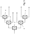
- a cascade-like arrangement of 2 n outputs can be implemented with the aid of a plurality of optical switching units which have at least two outputs.
- the individual HEL effector consists of a shared, central pump source, as well as at least one separate MOPA or at least one separate oscillator and at least one separate beam guidance system.
- the respective MOPA or the respective oscillator of the HEL effectors can be accommodated in the vicinity of the beam guidance system of the HEL effector.
- a direct connection to the platform together with the beam guidance system is also conceivable.
- optical connection between the pump source and the amplifiers of the MOPA or the oscillators is preferably made via optical fibers.
- a free jet variant is also possible.
- the optical connection of the central pump source with the oscillators or the amplifiers of the MOPA also takes place here via at least one optical switching unit.
- the optical switching unit can also be an optical switch or an optical switching splitter here.
- the optical switching unit can result in a line of action, for example: Pump unit - fiber (optical path) - optical switching unit - fiber (optical path) - oscillator or amplifier. If several oscillators are used, the outputs of the optical switching unit(s) are connected to a pump input (active medium) of the oscillator, preferably by means of optical fibers.
- an optical connection (fiber, free beam) can be implemented between the at least one optical switch and the amplifiers or oscillators with a significantly greater distance than a few meters despite the high power.
- modifications in which an optical link is missing are also conceivable in this embodiment.
- Another possibility is to provide a shareable master oscillator (MO) separate from the pump source instead of the many individual master oscillators.
- MO master oscillator
- the optical connections between the pump source and the amplifiers of the HEL effectors are made according to the second embodiment.
- the created central master oscillator can be located close to the pump source, which simplifies the power supply and cooling of the master oscillator.
- the output of the master oscillator can be switched to at least one input of the amplifier (PA) of the HEL effectors via at least one further optical switching unit.
- the individual amplifiers Due to the low weight of the individual amplifiers, they can be mounted directly on the platform with the beam guidance system. This enables good beam quality from the amplifier to be coupled into the beam guidance system at high power.
- the optical connection e.g. optical fiber, between the master oscillator and the amplifiers.
- the individual HEL effector in this third, also preferred version consists of a shared central pump source, a shared master oscillator (MO), its own amplifiers (PA) and its own beam guidance systems.
- An additional control can also be used to determine which of the MOPA, amplifier (PA) or oscillator(s) to be switched on should be supplied with which percentage of laser or pump power. For each HEL effector, the beam power of the laser or pump source can be set and/or varied. This percentage is controllable by means of the optical switching unit(s).
- the optical switching units can be spaced apart from the central laser source or the central pump source and possibly from the central master oscillator (MO). Due to the low beam quality of the pump diodes, an optical connection (fiber, free beam), in particular between the optical switch units and the amplifiers or oscillators, can be implemented with a distance that is significantly greater than a few meters. If the beam quality is poor, the beam transport takes place in fibers with a larger core diameter at reduced intensity, so that non-linear processes are reduced.
- MO central master oscillator
- the HEL effectors can be switched to a safe state via the optical switching unit(s).
- central laser sources pump sources and further central master oscillators etc.
- pump sources can also be provided as key components that can be used jointly. This enables the creation of a redundant system.
- HEL effectors can also be combined into groups, which can then be operated in parallel.
- the laser source, pump source, possibly the central master oscillator power amplifier (MOPA) or the central master oscillator (MO) or central oscillator can now preferably be accommodated inside the object, eg in the hull of a ship or vehicle. These components are no longer exposed to the environmental requirements on the object.
- a further advantage results from a local separation. In this way, the individual components can be installed in smaller spaces on the property, for example in niches.
- the mode of action is generalized as follows: If a target or a threat is detected, it is determined, for example by a weapon deployment system, which of the beam guidance system(s) of the HEL effect locations located on the object can bring about the best possible defense or neutralization of the threat as quickly as possible. Such methods are known to those skilled in the art.
- the weapon deployment system decides which beam guidance system(s) are to be used. Alternatively, this can also be initiated by an operator. Based on this decision, the selected beam guidance system(s) are optically linked, as already described.
- the optical switching unit(s) can be switched pneumatically, hydraulically, as well as electrically or electro-optically, although other possibilities are not excluded. The switching is controlled by the central control unit.
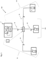
- a laser source 1 and at least two beam guidance systems 2.1, 2.2, 2.3 are shown as key components of several, at least two, HEL effectors 5.1, 5.2, 5.3.
- the laser source 1 contains at least one pump source 10, which is formed by at least one pump diode.
- the pump source 10 can be powered and cooled by a power and cooling system 11 .
- This energy supply and cooling system 11 can be part of the laser source 1 .
- a master oscillator power amplifier (MOPA) 12 eg seed laser+amplifier
- an oscillator (single resonator) 13 can also be used.
- the individual beam guidance systems 2.1, 2.2, 2.3 of the HEL effectors 5.1, 5.2, 5.3 can be connected to the laser source 1 via an optical switching unit 4.
- the HEL effectors 5.1, 5.2, 5.3 thus have a common laser source 1 and individual beam guidance systems 2.1, 2.2, 2.3 as their key components.
- the optical switching unit 4 can be an optical switch or an optical switch.
- the optical switching unit has at least one input and at least two outputs.
- the optical switching unit 4 should be designed to be able to divide the laser power generated in the laser source 1 (optical power) for the beam guides 2.1, 2.2, 2.3 of the HEL effectors 5.1, 5.2, 5.3.
- the distribution can be continuous or in several stages.
- the optical power can be divided between 0 and 100%. Provision is also made for the optical power to be split up simultaneously, so that a plurality of beam guides 2.1, 2.2, 2.3 can be supplied with optical power simultaneously by the optical switching unit 4. If the optical switching unit 4 has, for example, only two outputs, a cascade can be set up using a plurality of optical switching units 4, via which the laser power can be distributed to the beam guides 2.1, 2.2, 2.3 ( figure 5 ).
- the output of the laser source 1 is optically (15) connected to an input of the optical switching unit 4, ideally by an optical fiber. Freewheeling is also possible.
- the multiple outputs of the optical switching unit 4 are routed to inputs of the beam guidance systems 2.1, 2.2, 2.3 via optical connections 15.
- the switching of the optical switching unit 4 is controlled by an additional controller 6
- the beam guidance systems 2.1, 2.2, 2.3 can in turn be mounted on a platform 7, 8, 9.
- the platforms 7, 8, 9 are in turn preferably movable, so that the beam guidance systems 2.1, 2.2, 2.3 of the HEL effectors 5.1, 5.2, 5.3 can be pivoted in azimuth and/or elevation. This enables the HEL Effectors 5.1, 5.2, 5.3 to be directed towards the threat(s).
- the HEL effectors 5.1, 5.2, 5.3 are formed by the common, central laser source 1, the optical switching unit 4, their own beam guidance systems 2.1, 2.2, 2.3 and the optical connections 15, ideally optical fibers.
- HEL effectors 5.1, 5.2, 5.3 can be combined into a weapon system 100.
- a weapon deployment system e.g. a fire control system (not shown) determines which beam guidance system 2.1, 2.2, 2.3 would achieve good defense against the threat.
- this information is given to the controller 6.
- This switches the optical switching unit 4 in such a way that the optical power of the laser source 1 is transmitted via the switched output of the optical switching unit 4 and the input of the selected beam guidance system 2.1.
- This beam guidance system 2.1 emits the optical power against the threat.
- the optical power of the laser source 1 can also be throttled (less than 100%) to the beam guidance system 2.1 by the optical switching unit 4. If the fire control determines that more than one beam guidance system 2.1, 2.2, 2.3 is used for defense, the optical power of the laser source 1 is divided and this divided optical power is applied to the inputs of the beam guidance systems 2.1, 2.2, 2.3 intended or specified for defense directed. From these, the optical power can then be turned away of the threat against them are radiated.
- the beam guidance systems 2.1, 2.2, 2.3 can be directed at one threat together or separately at different threats.
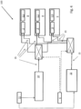
- FIGS. 2 and 3 show a variant of the solution according to the 1 as a second embodiment.
- the MOPP 12 or the oscillator 13 is detached from the laser source 1 in the second exemplary embodiment.
- a central pump source 10 is created, which generates the required pump power for all HEL effectors 5.1, 5.2, 5.3.
- oscillators 21.1, 21.2, 21.3 are provided for the HEL effectors 5.1, 5.2, 5.3.
- An output of the respective oscillator 21.1, 21.2, 21.3 is routed to the associated beam guidance system 2.1, 2.2, 2.3.
- the oscillators 21.1, 21.2, 21.3 are supplied with pump power from the pump source 10 via the optical switching unit 4.
- the optical switching unit 4 is switched as for FIG 1 described.
- the MOPP 12 can also be divided into several MOPA 22.1, 22.2, 22.3 ( 3 ). These MOPPs 22.1, 22.2, 22.3 can be placed near the platforms 7,8,9. An output of the amplifier of the MOPP 22.1, 22.2, 22.3 is aligned with the associated beam guidance system 2.1, 2.2, 2.3.
- the amplifiers of the MOPA 22.1, 22.2, 22.3 are supplied with pump power from the pump source 10 via the optical switching unit 4.
- the optical switching unit 4 operates and is switched as for FIG 1 described.
- the HEL effectors 5.1, 5.2, 5.3 are powered by a common pump source 10 (plus energy supply and cooling device 11), the optical switching unit 4, the oscillators 21.1, 21.2, 21.3 or MOPA 22.1, 22.2, 22.3 and their own Beam guides 2.1, 2.2, 2.3 and the optical connections 15, ideally optical fibers formed.
- FIG. 4 shows another solution variant of the inventive idea, starting from 3 .
- the embodiment after 3 shows the variant according to which the entire MOPA 22.2, 22.3 can be attached separately from the pump source 10 in the vicinity of the pump source 10 or the beam guidance systems 2.1, 2.2, 2.3.
- a further optical switching unit 14 is used for this embodiment, which, like the optical switching unit 4 for the pump power, can also connect the central master oscillator 22 to the individual amplifiers .1, .2, .3 at the same time.
- This optical switching unit 14 should be able to meet the same requirements as the optical switching unit 4 .
- the optical switching unit 14 is located between the output of the master oscillator 22 and an input of the amplifier .1, .2, .3 and switches the output of the master oscillator 22 to the respective input of the amplifier .1, .2, .3. Another input of the amplifiers .1, .2, .3 is reserved for feeding in the pump power of the pump source 10 .
- the HEL effectors 5.1, 5.2, 5.3 are activated by a central pump source 10, a central master oscillator (MO) 22, the individual, dedicated amplifiers) .1, .2, .3, which are based on the dedicated beam guidance system 2.1 , 2.2, 2.3 are aligned, and the optical connections 15, ideally optical fibers created.
- a central pump source 10 a central master oscillator (MO) 22
- the individual, dedicated amplifiers .1, .2, .3, which are based on the dedicated beam guidance system 2.1 , 2.2, 2.3 are aligned, and the optical connections 15, ideally optical fibers created.
- more than one weapon system 100 can also be attached to the object within the scope of the inventive idea, e.g. a port-side weapon system or a starboard-side weapon system etc.
Landscapes
- Physics & Mathematics (AREA)
- Electromagnetism (AREA)
- Engineering & Computer Science (AREA)
- Optics & Photonics (AREA)
- Plasma & Fusion (AREA)
- Remote Sensing (AREA)
- Radar, Positioning & Navigation (AREA)
- General Engineering & Computer Science (AREA)
- Microelectronics & Electronic Packaging (AREA)
- Lasers (AREA)
- Laser Beam Processing (AREA)
- Aiming, Guidance, Guns With A Light Source, Armor, Camouflage, And Targets (AREA)
- Telescopes (AREA)
- Organic Low-Molecular-Weight Compounds And Preparation Thereof (AREA)
- Separation By Low-Temperature Treatments (AREA)
Applications Claiming Priority (2)
| Application Number | Priority Date | Filing Date | Title |
|---|---|---|---|
| DE102017104662.3A DE102017104662B4 (de) | 2017-03-06 | 2017-03-06 | Waffensystem mit wenigstens zwei HEL-Effektoren |
| PCT/EP2018/052400 WO2018162148A1 (de) | 2017-03-06 | 2018-01-31 | Waffensystem mit wenigstens zwei hel-effektoren |
Publications (2)
| Publication Number | Publication Date |
|---|---|
| EP3593082A1 EP3593082A1 (de) | 2020-01-15 |
| EP3593082B1 true EP3593082B1 (de) | 2023-07-12 |
Family
ID=61132437
Family Applications (1)
| Application Number | Title | Priority Date | Filing Date |
|---|---|---|---|
| EP18702497.1A Active EP3593082B1 (de) | 2017-03-06 | 2018-01-31 | Waffensystem mit wenigstens zwei hel-effektoren |
Country Status (13)
| Country | Link |
|---|---|
| US (1) | US11402181B2 (pl) |
| EP (1) | EP3593082B1 (pl) |
| JP (1) | JP7114620B2 (pl) |
| KR (1) | KR102325871B1 (pl) |
| AU (1) | AU2018231279B2 (pl) |
| BR (1) | BR112019013233B1 (pl) |
| CA (1) | CA3054569C (pl) |
| DE (1) | DE102017104662B4 (pl) |
| DK (1) | DK3593082T3 (pl) |
| IL (1) | IL267400B2 (pl) |
| PL (1) | PL3593082T3 (pl) |
| SA (1) | SA519410015B1 (pl) |
| WO (1) | WO2018162148A1 (pl) |
Families Citing this family (2)
| Publication number | Priority date | Publication date | Assignee | Title |
|---|---|---|---|---|
| DE102018100891A1 (de) | 2018-01-16 | 2019-07-18 | Rheinmetall Waffe Munition Gmbh | Hochleistungslaser, insbesondere Laserwaffe |
| DE102021006230B4 (de) | 2021-12-17 | 2024-08-08 | SDT Industrial Technology UG (haftungsbeschränkt) | Universeller laser-komplex zur fernentsorgung von technischen konstruktionen |
Family Cites Families (23)
| Publication number | Priority date | Publication date | Assignee | Title |
|---|---|---|---|---|
| DE3318686A1 (de) | 1983-05-21 | 1984-11-22 | Diehl GmbH & Co, 8500 Nürnberg | Einrichtung zum ausrichten eines laserstrahles |
| US5208699A (en) | 1991-12-20 | 1993-05-04 | Hughes Aircraft Company | Compensated, SBS-free optical beam amplification and delivery apparatus and method |
| US6219360B1 (en) | 1998-04-24 | 2001-04-17 | Trw Inc. | High average power solid-state laser system with phase front control |
| US6665063B2 (en) * | 2001-09-04 | 2003-12-16 | Rosemount Aerospace Inc. | Distributed laser obstacle awareness system |
| US6873893B1 (en) * | 2003-08-01 | 2005-03-29 | The United States Of America As Represented By The Secretary Of The Navy | Missile warning and protection system for aircraft platforms |
| FR2864217B1 (fr) | 2003-12-19 | 2008-02-08 | Tda Armements Sas | Dispositif de mise a feu optique notamment pour la protection active de vehicules. |
| US7088743B2 (en) * | 2004-03-15 | 2006-08-08 | Northrop Grumman Corp. | Laser source comprising amplifier and adaptive wavefront/polarization driver |
| US7342651B1 (en) | 2004-12-27 | 2008-03-11 | Northrop Grumman Corporation | Time modulated doublet coherent laser radar |
| IL167740A (en) | 2005-03-30 | 2010-11-30 | Rafael Advanced Defense Sys | Fiber laser device for neutralizing unexploded ordnance |
| US7405834B1 (en) * | 2006-02-15 | 2008-07-29 | Lockheed Martin Corporation | Compensated coherent imaging for improved imaging and directed energy weapons applications |
| US20100254154A1 (en) * | 2006-04-12 | 2010-10-07 | Flight Safety Technologies, Inc | Central laser source based passive countermeasure system |
| DE202006010661U1 (de) * | 2006-07-10 | 2007-02-22 | Merlaku, Kastriot | Strahlen-Waffe |
| IL179453A (en) | 2006-11-21 | 2013-10-31 | Rafael Advanced Defense Sys | Laser-supported method and system |
| US8575528B1 (en) * | 2010-03-03 | 2013-11-05 | Jeffrey D. Barchers | System and method for coherent phased array beam transmission and imaging |
| DE102010051097A1 (de) | 2010-11-12 | 2012-05-16 | Rheinmetall Waffe Munition Gmbh | Lasersystem, zur Erzeugung von hohen bzw. kompakten Leistungsdichten am Objekt |
| JP5894433B2 (ja) | 2011-12-26 | 2016-03-30 | 株式会社小糸製作所 | 車両用灯具 |
| DE102012015074C5 (de) | 2012-07-31 | 2018-03-29 | Mbda Deutschland Gmbh | Neuartige Strahleinrichtung für ein Laserwaffensystem |
| US9077150B2 (en) | 2012-08-07 | 2015-07-07 | Ipg Photonics Corporation | High power ultra-compact, lightweight multi-kilowatt fiber laser system based on coherent and spectral beam combining |
| DE102012022039B4 (de) * | 2012-11-09 | 2020-03-26 | Mbda Deutschland Gmbh | Modulare Laserbestrahlungseinheit |
| JP6025535B2 (ja) | 2012-12-03 | 2016-11-16 | 三菱重工業株式会社 | 指向性エネルギー照射装置 |
| JP5807192B2 (ja) | 2013-01-21 | 2015-11-10 | パナソニックIpマネジメント株式会社 | 測定装置および測定方法 |
| FR3023423B1 (fr) | 2014-07-03 | 2016-07-08 | Amplitude Systemes | Systeme laser uv-visible a impulsions ultra-courtes de forte puissance et/ou de forte energie |
| IL234036B (en) * | 2014-08-10 | 2018-11-29 | Rafael Advanced Defense Systems Ltd | A directed energy based weapon |
-
2017
- 2017-03-06 DE DE102017104662.3A patent/DE102017104662B4/de active Active
-
2018
- 2018-01-31 KR KR1020197029340A patent/KR102325871B1/ko active Active
- 2018-01-31 DK DK18702497.1T patent/DK3593082T3/da active
- 2018-01-31 PL PL18702497.1T patent/PL3593082T3/pl unknown
- 2018-01-31 AU AU2018231279A patent/AU2018231279B2/en active Active
- 2018-01-31 EP EP18702497.1A patent/EP3593082B1/de active Active
- 2018-01-31 WO PCT/EP2018/052400 patent/WO2018162148A1/de not_active Ceased
- 2018-01-31 JP JP2019548715A patent/JP7114620B2/ja active Active
- 2018-01-31 BR BR112019013233-3A patent/BR112019013233B1/pt active IP Right Grant
- 2018-01-31 CA CA3054569A patent/CA3054569C/en active Active
-
2019
- 2019-06-16 IL IL267400A patent/IL267400B2/en unknown
- 2019-09-02 SA SA519410015A patent/SA519410015B1/ar unknown
- 2019-09-06 US US16/563,319 patent/US11402181B2/en active Active
Also Published As
| Publication number | Publication date |
|---|---|
| DK3593082T3 (da) | 2023-09-25 |
| JP2020509335A (ja) | 2020-03-26 |
| JP7114620B2 (ja) | 2022-08-08 |
| BR112019013233A2 (pt) | 2019-12-24 |
| DE102017104662B4 (de) | 2025-03-13 |
| CA3054569C (en) | 2022-05-17 |
| DE102017104662A1 (de) | 2018-09-06 |
| KR102325871B1 (ko) | 2021-11-12 |
| PL3593082T3 (pl) | 2024-01-22 |
| IL267400B1 (en) | 2023-03-01 |
| US20200003531A1 (en) | 2020-01-02 |
| CA3054569A1 (en) | 2018-09-13 |
| NZ754419A (en) | 2021-01-29 |
| KR20190126116A (ko) | 2019-11-08 |
| EP3593082A1 (de) | 2020-01-15 |
| IL267400A (en) | 2019-08-29 |
| SA519410015B1 (ar) | 2022-08-21 |
| BR112019013233B1 (pt) | 2023-12-05 |
| AU2018231279B2 (en) | 2021-01-28 |
| AU2018231279A1 (en) | 2019-07-04 |
| WO2018162148A1 (de) | 2018-09-13 |
| US11402181B2 (en) | 2022-08-02 |
| IL267400B2 (en) | 2023-07-01 |
Similar Documents
| Publication | Publication Date | Title |
|---|---|---|
| EP2638356B1 (de) | Lasersystem, zur erzeugung von hohen bzw. kompakten leistungsdichten am objekt | |
| DE19745785A1 (de) | Laserstrahlungsquelle für ein DIRCM-Waffensystem | |
| DE9417451U1 (de) | Einrichtung zur Abwehr eines angreifenden Flugkörpers | |
| EP2857792B2 (de) | Luftgestütztes Laserwaffensystem | |
| DE102012015074B3 (de) | Neuartige Strahleinrichtung für ein Laserwaffensystem | |
| DE102011009459B4 (de) | Verfahren und Vorrichtung zum Abwehren eines angreifenden Flugkörpers | |
| DE4402855C2 (de) | Einrichtung zur Abwehr eines angreifenden Luftziel-Flugkörpers | |
| DE102017104662B4 (de) | Waffensystem mit wenigstens zwei HEL-Effektoren | |
| EP2165151A1 (de) | Verfahren und abschussvorrichtung zum schutz eines objektes vor einer bedrohung, insbesondere einem flugkörper, sowie munition | |
| DE102018100891A1 (de) | Hochleistungslaser, insbesondere Laserwaffe | |
| EP4631145A1 (de) | Laserstrahlvorrichtung und verfahren zur kohärenzerzeugung | |
| DE2533270C2 (de) | Thermisches Visier- und Ortungsverfahren für die automatische Lenkung von Flugkörpern und Einrichtung dafür | |
| DE3343604A1 (de) | Verfahren und einrichtung zum bekaempfen von bodenzielen mittels eines gelenkten flugkoerpers | |
| EP3282216B1 (de) | Vorrichtung zur schädigung mittels gerichteter strahlung | |
| DE102024001907B3 (de) | Luftgestütztes Laserwaffensystem | |
| CH712974A2 (de) | Vorrichtung zur Steuerung einer Abfangdrohne. | |
| DE102004002471A1 (de) | Vorrichtung und Verfahren zur Abgabe einer Antriebsenergie | |
| DE102011116288B4 (de) | Unterwasserfahrzeug mit einem optischen Strahlenwirksystem | |
| DE102023005328A1 (de) | Skalierbare HPEM-Wirkanordnung gegen Bedrohungen mit mehreren Zielen | |
| DE102020002555A1 (de) | Verfahren zur Wirkoptimierung mittels iterativer Zielerkennung eines Zielobjekts während eines Zielanflugs mit einem Lenkflugkörper |
Legal Events
| Date | Code | Title | Description |
|---|---|---|---|
| STAA | Information on the status of an ep patent application or granted ep patent |
Free format text: STATUS: UNKNOWN |
|
| STAA | Information on the status of an ep patent application or granted ep patent |
Free format text: STATUS: THE INTERNATIONAL PUBLICATION HAS BEEN MADE |
|
| PUAI | Public reference made under article 153(3) epc to a published international application that has entered the european phase |
Free format text: ORIGINAL CODE: 0009012 |
|
| STAA | Information on the status of an ep patent application or granted ep patent |
Free format text: STATUS: REQUEST FOR EXAMINATION WAS MADE |
|
| 17P | Request for examination filed |
Effective date: 20190527 |
|
| AK | Designated contracting states |
Kind code of ref document: A1 Designated state(s): AL AT BE BG CH CY CZ DE DK EE ES FI FR GB GR HR HU IE IS IT LI LT LU LV MC MK MT NL NO PL PT RO RS SE SI SK SM TR |
|
| AX | Request for extension of the european patent |
Extension state: BA ME |
|
| DAV | Request for validation of the european patent (deleted) | ||
| DAX | Request for extension of the european patent (deleted) | ||
| STAA | Information on the status of an ep patent application or granted ep patent |
Free format text: STATUS: EXAMINATION IS IN PROGRESS |
|
| 17Q | First examination report despatched |
Effective date: 20200910 |
|
| RAP3 | Party data changed (applicant data changed or rights of an application transferred) |
Owner name: RHEINMETALL WAFFE MUNITION GMBH |
|
| GRAP | Despatch of communication of intention to grant a patent |
Free format text: ORIGINAL CODE: EPIDOSNIGR1 |
|
| STAA | Information on the status of an ep patent application or granted ep patent |
Free format text: STATUS: GRANT OF PATENT IS INTENDED |
|
| INTG | Intention to grant announced |
Effective date: 20220915 |
|
| GRAJ | Information related to disapproval of communication of intention to grant by the applicant or resumption of examination proceedings by the epo deleted |
Free format text: ORIGINAL CODE: EPIDOSDIGR1 |
|
| STAA | Information on the status of an ep patent application or granted ep patent |
Free format text: STATUS: EXAMINATION IS IN PROGRESS |
|
| GRAP | Despatch of communication of intention to grant a patent |
Free format text: ORIGINAL CODE: EPIDOSNIGR1 |
|
| STAA | Information on the status of an ep patent application or granted ep patent |
Free format text: STATUS: GRANT OF PATENT IS INTENDED |
|
| INTC | Intention to grant announced (deleted) | ||
| INTG | Intention to grant announced |
Effective date: 20230123 |
|
| GRAS | Grant fee paid |
Free format text: ORIGINAL CODE: EPIDOSNIGR3 |
|
| GRAA | (expected) grant |
Free format text: ORIGINAL CODE: 0009210 |
|
| STAA | Information on the status of an ep patent application or granted ep patent |
Free format text: STATUS: THE PATENT HAS BEEN GRANTED |
|
| AK | Designated contracting states |
Kind code of ref document: B1 Designated state(s): AL AT BE BG CH CY CZ DE DK EE ES FI FR GB GR HR HU IE IS IT LI LT LU LV MC MK MT NL NO PL PT RO RS SE SI SK SM TR |
|
| REG | Reference to a national code |
Ref country code: CH Ref legal event code: EP |
|
| REG | Reference to a national code |
Ref country code: IE Ref legal event code: FG4D Free format text: LANGUAGE OF EP DOCUMENT: GERMAN |
|
| REG | Reference to a national code |
Ref country code: DE Ref legal event code: R096 Ref document number: 502018012665 Country of ref document: DE |
|
| REG | Reference to a national code |
Ref country code: DK Ref legal event code: T3 Effective date: 20230922 |
|
| REG | Reference to a national code |
Ref country code: NL Ref legal event code: FP |
|
| REG | Reference to a national code |
Ref country code: LT Ref legal event code: MG9D |
|
| REG | Reference to a national code |
Ref country code: NO Ref legal event code: T2 Effective date: 20230712 |
|
| PG25 | Lapsed in a contracting state [announced via postgrant information from national office to epo] |
Ref country code: GR Free format text: LAPSE BECAUSE OF FAILURE TO SUBMIT A TRANSLATION OF THE DESCRIPTION OR TO PAY THE FEE WITHIN THE PRESCRIBED TIME-LIMIT Effective date: 20231013 |
|
| PG25 | Lapsed in a contracting state [announced via postgrant information from national office to epo] |
Ref country code: ES Free format text: LAPSE BECAUSE OF FAILURE TO SUBMIT A TRANSLATION OF THE DESCRIPTION OR TO PAY THE FEE WITHIN THE PRESCRIBED TIME-LIMIT Effective date: 20230712 |
|
| PG25 | Lapsed in a contracting state [announced via postgrant information from national office to epo] |
Ref country code: IS Free format text: LAPSE BECAUSE OF FAILURE TO SUBMIT A TRANSLATION OF THE DESCRIPTION OR TO PAY THE FEE WITHIN THE PRESCRIBED TIME-LIMIT Effective date: 20231112 |
|
| PG25 | Lapsed in a contracting state [announced via postgrant information from national office to epo] |
Ref country code: SE Free format text: LAPSE BECAUSE OF FAILURE TO SUBMIT A TRANSLATION OF THE DESCRIPTION OR TO PAY THE FEE WITHIN THE PRESCRIBED TIME-LIMIT Effective date: 20230712 Ref country code: RS Free format text: LAPSE BECAUSE OF FAILURE TO SUBMIT A TRANSLATION OF THE DESCRIPTION OR TO PAY THE FEE WITHIN THE PRESCRIBED TIME-LIMIT Effective date: 20230712 Ref country code: PT Free format text: LAPSE BECAUSE OF FAILURE TO SUBMIT A TRANSLATION OF THE DESCRIPTION OR TO PAY THE FEE WITHIN THE PRESCRIBED TIME-LIMIT Effective date: 20231113 Ref country code: LV Free format text: LAPSE BECAUSE OF FAILURE TO SUBMIT A TRANSLATION OF THE DESCRIPTION OR TO PAY THE FEE WITHIN THE PRESCRIBED TIME-LIMIT Effective date: 20230712 Ref country code: LT Free format text: LAPSE BECAUSE OF FAILURE TO SUBMIT A TRANSLATION OF THE DESCRIPTION OR TO PAY THE FEE WITHIN THE PRESCRIBED TIME-LIMIT Effective date: 20230712 Ref country code: IS Free format text: LAPSE BECAUSE OF FAILURE TO SUBMIT A TRANSLATION OF THE DESCRIPTION OR TO PAY THE FEE WITHIN THE PRESCRIBED TIME-LIMIT Effective date: 20231112 Ref country code: HR Free format text: LAPSE BECAUSE OF FAILURE TO SUBMIT A TRANSLATION OF THE DESCRIPTION OR TO PAY THE FEE WITHIN THE PRESCRIBED TIME-LIMIT Effective date: 20230712 Ref country code: GR Free format text: LAPSE BECAUSE OF FAILURE TO SUBMIT A TRANSLATION OF THE DESCRIPTION OR TO PAY THE FEE WITHIN THE PRESCRIBED TIME-LIMIT Effective date: 20231013 Ref country code: FI Free format text: LAPSE BECAUSE OF FAILURE TO SUBMIT A TRANSLATION OF THE DESCRIPTION OR TO PAY THE FEE WITHIN THE PRESCRIBED TIME-LIMIT Effective date: 20230712 Ref country code: ES Free format text: LAPSE BECAUSE OF FAILURE TO SUBMIT A TRANSLATION OF THE DESCRIPTION OR TO PAY THE FEE WITHIN THE PRESCRIBED TIME-LIMIT Effective date: 20230712 |
|
| REG | Reference to a national code |
Ref country code: DE Ref legal event code: R097 Ref document number: 502018012665 Country of ref document: DE |
|
| PG25 | Lapsed in a contracting state [announced via postgrant information from national office to epo] |
Ref country code: SM Free format text: LAPSE BECAUSE OF FAILURE TO SUBMIT A TRANSLATION OF THE DESCRIPTION OR TO PAY THE FEE WITHIN THE PRESCRIBED TIME-LIMIT Effective date: 20230712 Ref country code: RO Free format text: LAPSE BECAUSE OF FAILURE TO SUBMIT A TRANSLATION OF THE DESCRIPTION OR TO PAY THE FEE WITHIN THE PRESCRIBED TIME-LIMIT Effective date: 20230712 Ref country code: EE Free format text: LAPSE BECAUSE OF FAILURE TO SUBMIT A TRANSLATION OF THE DESCRIPTION OR TO PAY THE FEE WITHIN THE PRESCRIBED TIME-LIMIT Effective date: 20230712 Ref country code: CZ Free format text: LAPSE BECAUSE OF FAILURE TO SUBMIT A TRANSLATION OF THE DESCRIPTION OR TO PAY THE FEE WITHIN THE PRESCRIBED TIME-LIMIT Effective date: 20230712 Ref country code: SK Free format text: LAPSE BECAUSE OF FAILURE TO SUBMIT A TRANSLATION OF THE DESCRIPTION OR TO PAY THE FEE WITHIN THE PRESCRIBED TIME-LIMIT Effective date: 20230712 |
|
| PLBE | No opposition filed within time limit |
Free format text: ORIGINAL CODE: 0009261 |
|
| STAA | Information on the status of an ep patent application or granted ep patent |
Free format text: STATUS: NO OPPOSITION FILED WITHIN TIME LIMIT |
|
| 26N | No opposition filed |
Effective date: 20240415 |
|
| PG25 | Lapsed in a contracting state [announced via postgrant information from national office to epo] |
Ref country code: SI Free format text: LAPSE BECAUSE OF FAILURE TO SUBMIT A TRANSLATION OF THE DESCRIPTION OR TO PAY THE FEE WITHIN THE PRESCRIBED TIME-LIMIT Effective date: 20230712 |
|
| PG25 | Lapsed in a contracting state [announced via postgrant information from national office to epo] |
Ref country code: MC Free format text: LAPSE BECAUSE OF FAILURE TO SUBMIT A TRANSLATION OF THE DESCRIPTION OR TO PAY THE FEE WITHIN THE PRESCRIBED TIME-LIMIT Effective date: 20230712 |
|
| PG25 | Lapsed in a contracting state [announced via postgrant information from national office to epo] |
Ref country code: MC Free format text: LAPSE BECAUSE OF FAILURE TO SUBMIT A TRANSLATION OF THE DESCRIPTION OR TO PAY THE FEE WITHIN THE PRESCRIBED TIME-LIMIT Effective date: 20230712 |
|
| REG | Reference to a national code |
Ref country code: CH Ref legal event code: PL |
|
| PG25 | Lapsed in a contracting state [announced via postgrant information from national office to epo] |
Ref country code: LU Free format text: LAPSE BECAUSE OF NON-PAYMENT OF DUE FEES Effective date: 20240131 |
|
| PG25 | Lapsed in a contracting state [announced via postgrant information from national office to epo] |
Ref country code: LU Free format text: LAPSE BECAUSE OF NON-PAYMENT OF DUE FEES Effective date: 20240131 |
|
| PG25 | Lapsed in a contracting state [announced via postgrant information from national office to epo] |
Ref country code: BE Free format text: LAPSE BECAUSE OF NON-PAYMENT OF DUE FEES Effective date: 20240131 |
|
| PG25 | Lapsed in a contracting state [announced via postgrant information from national office to epo] |
Ref country code: CH Free format text: LAPSE BECAUSE OF NON-PAYMENT OF DUE FEES Effective date: 20240131 |
|
| PG25 | Lapsed in a contracting state [announced via postgrant information from national office to epo] |
Ref country code: CH Free format text: LAPSE BECAUSE OF NON-PAYMENT OF DUE FEES Effective date: 20240131 Ref country code: BE Free format text: LAPSE BECAUSE OF NON-PAYMENT OF DUE FEES Effective date: 20240131 |
|
| REG | Reference to a national code |
Ref country code: BE Ref legal event code: MM Effective date: 20240131 |
|
| PG25 | Lapsed in a contracting state [announced via postgrant information from national office to epo] |
Ref country code: BG Free format text: LAPSE BECAUSE OF FAILURE TO SUBMIT A TRANSLATION OF THE DESCRIPTION OR TO PAY THE FEE WITHIN THE PRESCRIBED TIME-LIMIT Effective date: 20230712 |
|
| PG25 | Lapsed in a contracting state [announced via postgrant information from national office to epo] |
Ref country code: BG Free format text: LAPSE BECAUSE OF FAILURE TO SUBMIT A TRANSLATION OF THE DESCRIPTION OR TO PAY THE FEE WITHIN THE PRESCRIBED TIME-LIMIT Effective date: 20230712 |
|
| PG25 | Lapsed in a contracting state [announced via postgrant information from national office to epo] |
Ref country code: IE Free format text: LAPSE BECAUSE OF NON-PAYMENT OF DUE FEES Effective date: 20240131 |
|
| PG25 | Lapsed in a contracting state [announced via postgrant information from national office to epo] |
Ref country code: IE Free format text: LAPSE BECAUSE OF NON-PAYMENT OF DUE FEES Effective date: 20240131 |
|
| REG | Reference to a national code |
Ref country code: AT Ref legal event code: MM01 Ref document number: 1587614 Country of ref document: AT Kind code of ref document: T Effective date: 20240131 |
|
| PG25 | Lapsed in a contracting state [announced via postgrant information from national office to epo] |
Ref country code: AT Free format text: LAPSE BECAUSE OF NON-PAYMENT OF DUE FEES Effective date: 20240131 |
|
| PG25 | Lapsed in a contracting state [announced via postgrant information from national office to epo] |
Ref country code: CY Free format text: LAPSE BECAUSE OF FAILURE TO SUBMIT A TRANSLATION OF THE DESCRIPTION OR TO PAY THE FEE WITHIN THE PRESCRIBED TIME-LIMIT; INVALID AB INITIO Effective date: 20180131 |
|
| PG25 | Lapsed in a contracting state [announced via postgrant information from national office to epo] |
Ref country code: HU Free format text: LAPSE BECAUSE OF FAILURE TO SUBMIT A TRANSLATION OF THE DESCRIPTION OR TO PAY THE FEE WITHIN THE PRESCRIBED TIME-LIMIT; INVALID AB INITIO Effective date: 20180131 |
|
| PGFP | Annual fee paid to national office [announced via postgrant information from national office to epo] |
Ref country code: PL Payment date: 20251229 Year of fee payment: 9 |
|
| PGFP | Annual fee paid to national office [announced via postgrant information from national office to epo] |
Ref country code: NL Payment date: 20260121 Year of fee payment: 9 |
|
| PGFP | Annual fee paid to national office [announced via postgrant information from national office to epo] |
Ref country code: GB Payment date: 20260123 Year of fee payment: 9 |
|
| PGFP | Annual fee paid to national office [announced via postgrant information from national office to epo] |
Ref country code: NO Payment date: 20260123 Year of fee payment: 9 Ref country code: DK Payment date: 20260126 Year of fee payment: 9 Ref country code: DE Payment date: 20260121 Year of fee payment: 9 |
|
| PGFP | Annual fee paid to national office [announced via postgrant information from national office to epo] |
Ref country code: IT Payment date: 20260126 Year of fee payment: 9 |
|
| PGFP | Annual fee paid to national office [announced via postgrant information from national office to epo] |
Ref country code: FR Payment date: 20260123 Year of fee payment: 9 |
|
| PGFP | Annual fee paid to national office [announced via postgrant information from national office to epo] |
Ref country code: TR Payment date: 20260127 Year of fee payment: 9 |