EP3592907B1 - Behältnis für ein wc-körbchen - Google Patents
Behältnis für ein wc-körbchen Download PDFInfo
- Publication number
- EP3592907B1 EP3592907B1 EP19711022.4A EP19711022A EP3592907B1 EP 3592907 B1 EP3592907 B1 EP 3592907B1 EP 19711022 A EP19711022 A EP 19711022A EP 3592907 B1 EP3592907 B1 EP 3592907B1
- Authority
- EP
- European Patent Office
- Prior art keywords
- container
- openings
- film
- water
- cleaning agent
- Prior art date
- Legal status (The legal status is an assumption and is not a legal conclusion. Google has not performed a legal analysis and makes no representation as to the accuracy of the status listed.)
- Active
Links
Images



Classifications
-
- E—FIXED CONSTRUCTIONS
- E03—WATER SUPPLY; SEWERAGE
- E03D—WATER-CLOSETS OR URINALS WITH FLUSHING DEVICES; FLUSHING VALVES THEREFOR
- E03D9/00—Sanitary or other accessories for lavatories ; Devices for cleaning or disinfecting the toilet room or the toilet bowl; Devices for eliminating smells
- E03D9/02—Devices adding a disinfecting, deodorising, or cleaning agent to the water while flushing
- E03D9/03—Devices adding a disinfecting, deodorising, or cleaning agent to the water while flushing consisting of a separate container with an outlet through which the agent is introduced into the flushing water, e.g. by suction ; Devices for agents in direct contact with flushing water
- E03D9/032—Devices connected to or dispensing into the bowl
-
- B—PERFORMING OPERATIONS; TRANSPORTING
- B29—WORKING OF PLASTICS; WORKING OF SUBSTANCES IN A PLASTIC STATE IN GENERAL
- B29C—SHAPING OR JOINING OF PLASTICS; SHAPING OF MATERIAL IN A PLASTIC STATE, NOT OTHERWISE PROVIDED FOR; AFTER-TREATMENT OF THE SHAPED PRODUCTS, e.g. REPAIRING
- B29C51/00—Shaping by thermoforming, i.e. shaping sheets or sheet like preforms after heating, e.g. shaping sheets in matched moulds or by deep-drawing; Apparatus therefor
- B29C51/002—Shaping by thermoforming, i.e. shaping sheets or sheet like preforms after heating, e.g. shaping sheets in matched moulds or by deep-drawing; Apparatus therefor characterised by the choice of material
-
- E—FIXED CONSTRUCTIONS
- E03—WATER SUPPLY; SEWERAGE
- E03D—WATER-CLOSETS OR URINALS WITH FLUSHING DEVICES; FLUSHING VALVES THEREFOR
- E03D9/00—Sanitary or other accessories for lavatories ; Devices for cleaning or disinfecting the toilet room or the toilet bowl; Devices for eliminating smells
- E03D9/02—Devices adding a disinfecting, deodorising, or cleaning agent to the water while flushing
- E03D2009/024—Devices adding a disinfecting, deodorising, or cleaning agent to the water while flushing using a solid substance
-
- E—FIXED CONSTRUCTIONS
- E03—WATER SUPPLY; SEWERAGE
- E03D—WATER-CLOSETS OR URINALS WITH FLUSHING DEVICES; FLUSHING VALVES THEREFOR
- E03D9/00—Sanitary or other accessories for lavatories ; Devices for cleaning or disinfecting the toilet room or the toilet bowl; Devices for eliminating smells
- E03D9/02—Devices adding a disinfecting, deodorising, or cleaning agent to the water while flushing
- E03D2009/026—Devices adding a disinfecting, deodorising, or cleaning agent to the water while flushing using a gel-form substance
-
- E—FIXED CONSTRUCTIONS
- E03—WATER SUPPLY; SEWERAGE
- E03D—WATER-CLOSETS OR URINALS WITH FLUSHING DEVICES; FLUSHING VALVES THEREFOR
- E03D9/00—Sanitary or other accessories for lavatories ; Devices for cleaning or disinfecting the toilet room or the toilet bowl; Devices for eliminating smells
- E03D9/02—Devices adding a disinfecting, deodorising, or cleaning agent to the water while flushing
- E03D2009/028—Devices adding a disinfecting, deodorising, or cleaning agent to the water while flushing using a liquid substance
Definitions
- the present invention relates to a container with openings for storing detergents for toilet bowls, the manufacturing process and the use of such a container.
- rim blocks which are attached to the edge of the toilet in basket-like or cage-like containers with a hook-shaped hanging device, the so-called toilet basket.
- the containers have inlet and outlet openings for the rinse water.
- the rinsing water flows over the agent in the container during each rinsing process.
- a small proportion of the detergent is released with each flush, releasing surfactants, fragrances, etc., which then achieves the desired cleaning of the toilet bowl and the toilet sump and the desired fragrance.
- the cleaning agents have fragrances and are colored for a visually appealing appearance.
- toilet baskets There are a large number of different toilet baskets in the prior art. Many toilet baskets have two bowl halves with inlet and outlet openings that are connected with a hinge so that the toilet basket can be opened and closed and the basket can be refilled after the agent has been used up.
- refillable baskets that have an opening that is open at the top or to the side, through which new piece-shaped toilet cleaning agents can be pushed into the basket after use.
- the containers are bowl-shaped, and the cleaning agent is poured into the bowl-shaped container during manufacture, for example as a melt, and then solidifies. After emptying, the empty container and possibly also the hanging device attached to it are thrown away.
- the toilet baskets are generally supplied in a blister pack together with the cleaning agents.
- the blister pack is not only used to attach the toilet basket and the detergent to the blister, but also to prevent the fragrances from evaporating from the detergent.
- WC baskets which generally have openings for the entry and exit of the flushing water, are often produced by injection molding.
- the injection molded baskets are dimensionally stable and visually appealing and can be produced in a variety of shapes.
- the manufacturing process is quite complex, a relatively large amount of plastic is used to produce such a basket and, in addition, a new injection mold has to be produced each time the shape of the basket changes, which is expensive.
- a container for a toilet cleaning agent which has two shell halves connected by a hinge, one shell half having one or more half shells for receiving detergent and no openings and the other shell half having recesses with openings on the side opposite the half shells which can reach the surface of the agent in the bowls and dissolve it.
- the openings are in a flat surface of the recess in the other half of the shell.
- cleaning agents in such a container do not rinse sufficiently well.
- the EP 3 214 232 A1 also teaches a toilet basket that can be produced by thermoforming and stamping. In order to ensure the flushing water outlet, this toilet basket in the operating position has a gap in the lower region between the first and the second half of the bowl through which the flushing water can escape from the basket.
- a toilet basket which has a hanging device with a releasable locking element and a blister-like cassette with a corresponding locking element, so that the cassette can be connected to the hanging device and the cassette can be removed from the hanging device after being emptied and replaced by a new cassette .
- the cassette has a bowl and a cover, and the bowl contains the cleaning agent, which can be poured into the bowl. For use, the cover is removed from the bowl and the hanging device with the detergent in the bowl is hung in the toilet bowl.
- the shell is closed except for the large entry opening and is produced by thermoforming.
- This toilet basket with replaceable cassette is hygienic and environmentally friendly, as it enables the hanging device to be reused and the container for the cleaning agent that reaches into the toilet bowl and which could possibly be dirty is thrown away.
- the fact that the shell is thermoformed also contributes to environmental friendliness and low manufacturing costs is produced from a film, which is inexpensive and which - compared to injection molding - can save a considerable amount of plastic.
- a method for filling a sanitary agent into a container is known.
- a container body is provided, which has slots and is used to hold gel-like sanitary materials.
- a water-soluble material is then placed over the slots in the container to cover the slots.
- the gel-like sanitary agent is then poured into the container and solidifies there.
- the container with the poured gel is now attached to the hanging device and hung in the toilet bowl.
- the water-soluble material in the slots dissolves and water reaches the gel-like cleaning agent through the slots.
- the container is manufactured using injection molding.
- This method makes it possible to provide gels cast in slotted dishes, the gels rinsing well in use due to the slits. After emptying, the gel trays can be removed from the hanging device and thrown away and replaced with a new filled gel tray.
- the object of the present invention is to provide a simple and inexpensive method for producing a container for toilet cleaning agents with a good dissolution behavior and a To provide an inexpensive and environmentally friendly container for cleaning agents for toilet bowls.
- the container for toilet cleaning agents according to the invention has openings for easy rinsing and can be produced inexpensively and in an environmentally friendly manner by means of thermoforming.
- one or more openings are punched into a polymer film, and the opening (s) are then closed again with a removable removable material that is essentially gas-tight.
- the film with the closed opening (s) is then shaped in a thermoforming process into the desired three-dimensional container shape, which is preferably bowl-shaped.
- the first step of the method according to the invention is the punching of the opening (s) into a flat polymer film, which can be accomplished simply and inexpensively. Through the openings, the passage of water into the interior of the container to the detergent to be dissolved should take place later in use in the finished container.
- the openings punched into the gas-tight film per se mean that the film with the openings cannot be shaped into the desired shape, in particular shell shape, by means of the thermoforming process, since the heated film cannot be shaped by means of compressed air or negative pressure as a result of the openings.
- the container with the poured-in or otherwise filled cleaning agent can then be closed with a container lid.
- the container lid is preferably also made of the polymer material and is also connected to the thermoformed container in a substantially gas-tight manner, for example by gluing.
- the container lid can also be a film that closes the container opening essentially gas-tight.
- Such a container with cleaning agent which is closed with a lid, can then be connected to a corresponding hanging device, which is used for fastening to the edge of the toilet, in particular clipped in, hung in or locked in place.
- a hanging device which is used for fastening to the edge of the toilet, in particular clipped in, hung in or locked in place.
- the container protruding into the toilet bowl and perceived by the consumer as unsanitary can be thrown away after emptying, but the hanging device that does not protrude into the toilet bowl can be reused.
- the container with the cleaning agent and / or the container lid preferably have means for releasably fastening the hanging device.
- the container is simply hung into hooks provided on the hanging device by means of corresponding slots provided on the lid. After emptying, the container is removed from the hook on the hanging device and can be replaced by a new container with cleaning agent.
- the container with the cleaning agent and the lid is latched, hung or clipped onto the hanging device.
- Other types of fastening such as push buttons, carabiners or magnetic closures are also possible.
- the method according to the invention makes it possible to dispense with the provision of an expensive stamping unit for stamping three-dimensional containers thermoformed from a polymer film, which would be required in a stamping step required after thermoforming.
- the container and the container cover formed from the stamped polymer film with the gas-tight sealing material are also essentially gas-tight, so that volatile compounds such as e.g. Cannot evaporate fragrances in a detergent in the container with a lid.
- the container with a lid sealed with the gas-tight closure material thus fulfills the requirements for an essentially gas-tight packaging, i.e. the container with the lid closed with the gas-tight sealing material can be offered without further blister packaging in a conventional non-gas-tight packaging such as a cardboard box, and the usual blister film and the associated costs can thus be dispensed with. It is also not necessary to "pack" the cleaning agent in a water-soluble film, which serves to prevent the fragrances from escaping and hands from getting dirty during handling.
- the container lid like the container, can also be produced from a polymer film with the punching of openings for the passage of water, subsequent lamination or closing of the openings with a preferably water-soluble sealing material and possibly subsequent deformation.
- Such a container with a container lid and flushable openings on both sides enables very good entry of the rinsing water from both sides and thus a good dissolution of the cleaning agent.
- Another advantage is that the cleaning agents packaged in the container according to the invention are not only gas-tight, but are also childproof at the same time.
- a water-soluble polymer material in particular a water-soluble polymer film, but also a self-adhesive label or a tear-open tab can be used as the gas-tight, removable removable closure material.
- a water-soluble polymer in particular a water-soluble polymer film
- this can be laminated very well onto the polymer film and thus a composite or a laminate can be produced in a simple manner can be made from polymer film and water-soluble films, which is then thermoformed.
- the openings in the polymer film are sealed with an essentially gas-tight label, so that the openings are closed in a gas-tight manner.
- the removable gas-tight material is a non-water-soluble label, it can simply be pulled off the openings again, for example, before the basket is put into use.
- containers with a lower weight and thus far less polymer material can be obtained. Since the containers are generally thrown away after emptying, containers with a lower polymer mass are environmentally friendly and, moreover, less expensive.
- thermoforming of containers with openings Another advantage of the thermoforming of containers with openings according to the invention is that the molds for the Thermoforming process are far easier and cheaper to manufacture than the molds for the injection molding process.
- the greatest cost of injection molding processes results from the cost of the injection mold.
- the method according to the invention with the far less expensive thermoforming molds is therefore particularly suitable for not very large numbers of containers with openings or if differently shaped containers with openings are desired.
- containers for almost any form of cleaning agent can be produced inexpensively and in a simple manner.
- Another advantage of the container according to the invention is that it can be produced from a transparent polymer material and the design of the respective cleaning agent is thus clearly visible to the consumer.
- thermoforming according to the invention is the lower energy requirement compared to injection molding.
- thermoplastic polymer material that can be produced in the form of films
- the polymer films should be essentially gas-tight.
- a film material made of polyethylene terephthalate (PET), polyethylene (PE), polypropylene (PP), polystyrene (PS), polyvinyl chloride (PVC) is preferably used. It is also possible to use recycled materials or multilayer films such as PS-EVOH-PE or PP-EVOH-PE (EVOH: ethylene-vinyl alcohol copolymer).
- the polymer film material should have a certain dimensional stability and give stability against mechanical stress during storage, transport and use. In addition, the film must have a certain resistance to external influences such as moisture or chemicals.
- the thickness of the polymer films is generally between 70 and 700 ⁇ m.
- a water-soluble polymer material in particular a polymer film, but also a non-water-soluble label made of paper or plastic can be used as the closure material.
- Closure materials based on renewable raw materials such as soy, milk proteins or starch can also be used.
- thermoplastic biodegradable granules which comprise caseinate or casein, plasticizers such as water, glycerol, sorbitol, mannitol, maltitol or ethylene glycol, and a biodegradable polyester, for example poly (butylene adipate cobutylene terephthalate).
- plasticizers such as water, glycerol, sorbitol, mannitol, maltitol or ethylene glycol
- a biodegradable polyester for example poly (butylene adipate cobutylene terephthalate).
- a thermoplastic biodegradable granulate is from the WO 2012/010421 A1 known.
- These water-soluble closure materials are preferably films and are preferably laminated onto the polymer film material in such a way that the polymer film material and the closure material film are essentially gas-tight.
- the bonding can be carried out, for example, using PVA solution, other solutions of water-soluble polymers or conventional laminating adhesives or spray adhesives, such as those offered by the Meyco company as "spray adhesives, crystal clear”.
- Gluing with water-soluble lamination adhesives, such as polyurethane-based adhesives is also possible.
- Such adhesives are sold, for example, as two-component adhesives BEST-PU 0587 by Best Klebstoffe GmbH & Co. KG.
- This sealing material film is preferably between 50 microns and 500 microns thick.
- Such films - for example made of PVA - are available under the name M8310 with a thickness of 88 ⁇ m from Monosol, LLC.
- Adhesion with waterless laminating adhesives such as PU-based adhesives is also possible.
- foils are at least so gas-tight that vacuum or compressed air can be applied briefly in order to deform the foils into the desired three-dimensional shape.
- the foils are preferably so dense that they form a barrier to water vapor or fragrances over a certain period of time.
- “essentially gas-tight” in the context of the present invention means that the concentration of a fragrance in a cleaning agent which is packaged with a film has decreased by at most 30% after 2 weeks, preferably by at most 20% after 2 weeks. and particularly preferably after 6 weeks by at most 20%.
- the container is trough-shaped and has a circumferential, flat edge running perpendicular to the trough walls, which is used for fastening, in particular gluing or welding to the lid. Openings for attachment to the hanging device can be provided on the cover.
- the hanger is generally made by injection molding. It has a hook for attachment to the edge of the toilet and means for attaching the container. In principle, several containers can also be attached to a hanging device.
- the container with the container lid After emptying, the container with the container lid, and thus all parts protruding into the toilet bowl, are thrown away. If the fastening means are now provided on the container lid and if these and thus also the corresponding fastening means are on the hanging device with a means fastened in the bowl above the cleaning agent, the probability of contamination of the reusable hanging device is low.
- the container lid is part of the hanging device and is molded onto it in the lower region.
- the container with the cleaning agent can then, for example, be clipped or pushed onto the lid located on the hanging device and removed again after emptying.
- this variant has the disadvantage that the consumer has to touch the end of the hanging device protruding into the toilet bowl with the lid when filling.
- Figure 1 and 2 show a container 11 having a semi-cylindrical shell 14 with a peripheral edge 15.
- the semi-cylindrical shell 14 serves to hold the cleaning agent 40.
- Figure 1 shows the view of the outside of the container 11, thus the view of the side which, when the container 11 is suspended in the toilet bowl 50, points in the direction of the toilet bowl wall 52, cf.
- Figure 4 shows a top view of the inside of the open container 11.
- the shell 14 five elongated openings 13 are provided, which are sealed gas-tight with a piece of film as the closure material 21.
- the film piece 21 is a in a first embodiment water-soluble film which is glued to the openings 13 on the outside 23 of the container 11.
- the piece of film 21 was glued to the openings 13 punched out in the polymer film 20, as described below.
- This water-soluble film 21 can be removed during the first use by rinsing with water and thus the openings 13 through which the water can reach the surface of the cleaning agent 40 can be rinsed free.
- the shell 14 can also have a different shape as long as it can be produced by means of thermoforming.
- the number, shape and arrangement of the openings 13 can of course also vary.
- the rinsing behavior and the number of rinses of the cleaning agent 40 can be changed by the size and number of the openings 13.
- the edge 15 serves to close the container 11 after filling with the cleaning agent 40 with the container lid 12, preferably in a gas-tight manner. Suitable and customary sealing methods such as heat sealing, ultrasonic sealing or gluing with an adhesive such as polyvinyl alcohol solution can be used.
- the width of the edge 15 is preferably between 2 mm and 10 mm.
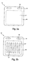
- Figure 3 Two variants of the container lid 12 are shown.
- Figure 3a shows a simple container lid 12 made of non-water-soluble polymer film 20, which with its dashed area 17 covers the openings 13 in the shell 14 and is connected with its edge 18 to the edge 15 of the container 11.
- the visible side 23 of the container lid 12 in the toilet bowl 50 can be decorative.
- a film section 19 with elongated fastening slots 16 is provided above the covering area 17. Through these mounting slots 16, the provided on the hanging device 31 Fastening hooks 32 are inserted so that the container 11 filled with the cleaning agent 40 can be fastened with the container lid 12 to the hanging device 31 at the edge of the toilet bowl 50, cf. Figure 4 .
- the container lid 12 which consists of a non-water-soluble plastic film 20 ', also has punched-in openings 13', which can also be closed with a water-soluble film 21 'in accordance with the previously described container 11.
- the container lid 12 is preferably flat, but it can also be three-dimensionally shaped in accordance with the container 11 by punching from a film, closing the openings 13 and then thermoforming.
- this water-soluble film 21 ' is also rinsed off when rinsed for the first time.
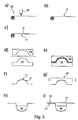
- Gas-impermeable polymer film 20 is unwound from a roll, and five elongated openings 13 are punched into the flat polymer film 20 in an area of approximately 40 ⁇ 60 mm using a punch 60, cf. Figure 5a , b.
- a water-soluble PVA film is now glued over the openings 13 as a gas-tight sealing material 21 with a polyvinyl alcohol solution as an adhesive, cf. Figure 5c , so that the openings 13 are closed gas-tight.
- the PVA film 21 can also be unwound from a roll and also laminated over the entire surface of the polymer film 20 with the punched openings 13, so that a composite or laminate is obtained.
- Essential in the process step in Figure 5c is that the composite of polymer film 20 with the openings 13 and the closure material 21 is gas-tight.
- the composite of polymer film 20 and sealing material 21 is then heated on one or both sides in a heating station.
- the prestretcher 61 and the thermoforming tool 62 then travel through the softened film plane and roughly specify the finished contour, cf. Figure 5d , e.
- compressed air comes from one side and vacuum from the other to bring the film quickly and strongly to the water-cooled wall (contour) of the molding tool (not shown).
- the air escapes between the film composite 20, 21 and the tool through small holes or slots.
- the cooled, now firm film composite 20, 21 is separated from the molding tool and fed to the punching station 60 'in the next working cycle, cf. Figure 5f , g.
- the cooled container 11 with the openings 13 and the laminated water-soluble film 21 is now filled with the hot detergent composition 40 and allowed to cool ( Figure 5h ).
- a solid, for example extruded or tableted, detergent tablet can also be inserted into the cavity.
- the container 11 is then sealed gas-tight with a container lid 12, which is sealed or glued to the edge 15 of the container 11, Fig. 5i .
- Figure 6 schematically shows the layer sequence of the film composite of the container 11.
- the composite consists of an external PVA film 21, which dissolves on contact with water, and one or more internal polymer films 20 with punched openings 13.
- the PVA film 21 is glued to the punched polymer film 20 with a laminating adhesive 22. After the first rinsing with water, the openings 13 become permeable because the PVA film 21 dissolves, so that water can get into the interior 35 of the container 11 from the outside space 34 and dissolve the cleaning agent 40 located there.
- the geometry and position of the openings 13 are selected such that they are not influenced or changed as little as possible by the shaping process during thermoforming.
- the outer closure material 21 is connected to the inner perforated film layer 20 by means of an elastic lamination adhesive 22 which is suitable for thermoforming.
- the lamination adhesive 22 is applied to the polymer film 20 in order not to influence the dissolution behavior of the PVA film 21 in the area of the openings 13.
- the lamination adhesive 22 can be based on polyurethane and can be a chemically curing two-component PU adhesive.
- a sealing layer 41 can be applied on the side of the polymer film 20 pointing in the direction of the interior 35 in order to enable an easier connection between the edge 15 of the shell 14 and the container lid 12 using a conventional heat sealing method.
- this layer 41 can consist of polyethylene or polypropylene.
Landscapes
- Health & Medical Sciences (AREA)
- Public Health (AREA)
- Engineering & Computer Science (AREA)
- Epidemiology (AREA)
- Life Sciences & Earth Sciences (AREA)
- Hydrology & Water Resources (AREA)
- Water Supply & Treatment (AREA)
- Mechanical Engineering (AREA)
- Packages (AREA)
- Blow-Moulding Or Thermoforming Of Plastics Or The Like (AREA)
- Bidet-Like Cleaning Device And Other Flush Toilet Accessories (AREA)
- Wrappers (AREA)
Description
- Die vorliegende Erfindung betrifft ein Behältnis mit Öffnungen zur Bevorratung von Reinigungsmitteln für WC-Körbchen, das Herstellungsverfahren und die Verwendung eines solchen Behältnisses.
- Ein Großteil der bekannten stückförmigen Reinigungsmittel sind so genannte "Rimblocks", die in körbchen- oder käfigartigen Behältnissen mit einer hakenförmigen Hängevorrichtung, den sogenannten WC-Körbchen, am Rand der Toilette befestigt werden. Die Behältnisse weisen Eintritts- und Austrittsöffnungen für das Spülwasser auf. Das in dem Behältnis befindliche Mittel wird bei jedem Spülvorgang von dem Spülwasser überströmt. Hierdurch wird bei jeder Spülung ein geringer Anteil des Reinigungsmittels unter Freisetzung von Tensiden, Duftstoffen etc. aufgelöst, wodurch dann die gewünschte Reinigung des Toilettenbeckens und des Toilettensumpfs und die gewünschte Beduftung erzielt werden.
- Im Allgemeinen weisen die Reinigungsmittel Duftstoffe auf und sind für ein optisch ansprechendes Aussehen eingefärbt.
- Im Stand der Technik gibt es eine Vielzahl unterschiedlicher WC-Körbchen. Viele WC-Körbchen weisen zwei Schalenhälften mit Eintritts- und Austrittsöffnungen auf, die mit einem Scharnier miteinander verbunden sind, so dass sich das WC-Körbchen öffnen und schließen lässt und das Körbchen nach Verbrauch des Mittels wieder gefüllt werden kann.
- Weiterhin gibt es wiederbefüllbare Körbchen, die eine nach oben oder zur Seite offene Öffnung aufweisen, durch die nach Verbrauch neue stückförmige WC-Reinigungsmittel in das Körbchen hineingeschoben werden können.
- Weiterhin gibt es Einmalkörbchen, die nach Verbrauch des Mittels weggeworfen werden. Bei den Einmalkörbchen gibt es wiederum WC-Körbchen, bei deren Herstellung das stückförmige Reinigungsmittel während des Herstellens in das Körbchen eingeschlossen wird. Ein solches Körbchen wird als Ganzes nach Entleerung entsorgt.
- In einer Variante von solchen Einmalkörbchen sind die Behältnisse schalenförmig, und das Reinigungsmittel wird während des Herstellens beispielsweise als Schmelze in das schalenförmige Behältnis gegossen und erstarrt dann. Nach der Entleerung werden das leere Behältnis und ggfs. auch die daran befindliche Hängevorrichtung weggeworfen.
- Die WC-Körbchen werden zusammen mit den Reinigungsmitteln im Allgemeinen in einer Blisterverpackung angeboten. Die Blisterverpackung dient nicht nur zur Befestigung des WC-Körbchens und des Reinigungsmittels an dem Blisterkarton, sondern auch dazu, ein Verdampfen der Duftstoffe aus dem Reinigungsmittel zu verhindern.
- Häufig werden WC-Körbchen, die im Allgemeinen Öffnungen zum Ein- und Austritt des Spülwassers aufweisen, mittels Spritzguss hergestellt. Die Spritzgusskörbchen sind formbeständig und optisch ansprechend und lassen sich in einer Vielzahl von Formen herstellen. Allerdings ist das Herstellungsverfahren recht aufwendig, zur Herstellung eines solchen Körbchens wird relativ viel Kunststoff eingesetzt und zudem muss bei Veränderung der Form des Körbchens jeweils eine neue Spritzgussform hergestellt werden, was teuer ist.
- Aus der
EP 3 121 342 A1 ist ein Behälter für ein WC-Reinigungsmittel bekannt, der zwei mit einem Scharnier verbundene Schalenhälften aufweist, wobei eine Schalenhälfte eine oder mehrere Halbschalen zur Aufnahme von Reinigungsmittel und keine Durchbrechungen aufweist und die andere Schalenhälfte auf der den Halbschalen gegenüberliegenden Seite Vertiefungen mit Durchbrechungen aufweist, durch die das Spülwasser an die Oberfläche des in den Näpfen befindlichen Mittels gelangen und dieses auflösen kann. Die Durchbrechungen befinden sich in einer ebenen Fläche der Vertiefung in der anderen Schalenhälfte. - Im geschlossenen Zustand bildet jeweils eine Halbschale und die Vertiefung mit der Durchbrechung eine Kammer zur Aufnahme des Reinigungsmittels. Dieses Behältnis wird am Rand der WC-Schüssel verklemmt.
- Durch die Ausgestaltung des Behälters lässt sich dieses durch Thermoformen und Stanzen aus einer Folie herstellen, so dass solche Behältnisse einfach und mit wenig Materialaufwand und somit kostengünstig herstellbar sind.
- Nachdem das Reinigungsmittel in diesem Behälter in der geschlossenen Halbschale aufgenommen ist und das Wasser an das Reinigungsmittel nur durch den Durchtritt des Spülwassers durch die Durchbrechungen in den Vertiefungen auf der gegenüberliegenden Seite gelangt, spülen sich Reinigungsmittel in solch einem Behältnis nicht hinreichend gut ab.
- Aufgrund der Ausgestaltung kann es zudem dazu kommen, dass Spülwasser in dem Behälter verbleibt und sich der Wirkstoff somit nicht richtig entfalten kann.
- Die
EP 3 214 232 A1 lehrt ebenfalls ein WC-Körbchen, das sich durch Thermoformen und Stanzen herstellen lässt. Um den Spülwasseraustritt zu gewährleisten, weist dieses WC-Körbchen in der Betriebsposition im unteren Bereich zwischen der ersten und der zweiten Schalenhälfte einen Spalt auf, durch den das Spülwasser aus dem Körbchen austreten kann. - Aus der
WO 2018/009336 A1 ist ein WC-Körbchen bekannt, das eine Hängevorrichtung mit einem lösbaren Rastelement und eine blisterartige Kassette mit einem korrespondierenden Rastelement aufweist, so dass die Kassette mit der Hängevorrichtung verbunden werden und die Kassette nach Entleerung von der Hängevorrichtung entfernt und durch eine neue Kassette ausgetauscht werden kann. Die Kassette weist eine Schale und eine Abdeckung auf, und in der Schale befindet sich das Reinigungsmittel, das in die Schale eingegossen sein kann. Zur Ingebrauchnahme wird die Abdeckung von der Schale entfernt und die Hängevorrichtung mit dem Reinigungsmittel in der Schale in die Toilettenschüssel gehängt. Die Schale ist bis auf die große Eintrittsöffnung geschlossen und wird durch Thermoformen hergestellt. - Dieses WC-Körbchen mit ersetzbarer Kassette ist hygienisch und umweltfreundlich, da es die Wiederverwendung der Hängevorrichtung ermöglicht und das Behältnis für das Reinigungsmittel, das in die Toilettenschüssel hineinreicht und das unter Umständen verschmutzt sein könnte, weggeworfen wird. Zur Umweltfreundlichkeit und zu geringen Herstellungskosten trägt auch bei, dass die Schale durch Thermoformen aus einer Folie hergestellt wird, was kostengünstig ist und wodurch - verglichen mit dem Spritzguss - eine erhebliche Menge an Kunststoff eingespart werden kann.
- Nachteilig ist jedoch auch bei diesem WC-Körbchen, dass sich das Mittel nicht hinreichend gut abspült.
- Aus der
EP 3 263 786 A1 ist ein Verfahren zum Befüllen eines Sanitärmittels in einen Behälter bekannt. Zunächst wird ein Behälterkörper, der Schlitze aufweist und zur Aufnahme von gelförmigen Sanitärmitteln dient, bereitgestellt. Anschließend wird ein wasserlösliches Material über die Schlitze in den Behälter gelegt, um die Schlitze abzudecken. In den Behälter wird nun das gelförmige Sanitärmittel gegossen, das dort erstarrt. Der Behälter mit dem eingegossenen Gel wird nun an der Hängevorrichtung befestigt und in die Toilettenschüssel gehängt. Beim ersten Spülen löst sich das in den Schlitzen befindliche wasserlösliche Material auf und Wasser gelangt durch die Schlitze zu dem gelförmigen Reinigungsmittel. - Die Herstellung des Behälters erfolgt mit Spritzguss.
- Dieses Verfahren ermöglicht es, in Schalen mit Schlitzen gegossene Gele bereitzustellen, wobei sich die Gele im Gebrauch infolge der Schlitze gut abspülen. Die Gelschalen können nach Entleerung von der Hängevorrichtung entfernt und weggeworfen und durch eine neue gefüllte Gelschale ersetzt werden.
- Aus der
WO 2016/040341 A1 ist ein Verfahren zur Herstellung eines Behältnisses mit wenigstens einer Öffnung zur Bevorratung von Reinigungsmittel für ein WC-Körbchen bekannt, wobei eine Polymerfolie bereitgestellt wird und in die Polymerfolie wenigstens eine Öffnung gestanzt wird und die wenigstens eine Öffnung mit einem im Wesentlichen gasdichten oder wieder entfernbaren Verschlussmaterial verschlossen wird. Dieses Dokument wird als nächstliegender Stand der Technik angesehen. Der Oberbegriff des Anspruchs 1 entspricht diesem Dokument. - Diese Verfahren sind allerdings aufwändig und kostenintensiv.
- Die Aufgabe der vorliegenden Erfindung besteht darin, ein einfaches und kostengünstiges Verfahren zum Herstellen eines Behältnisses für WC-Reinigungsmittel mit einem guten Auflöseverhalten anzugeben und ein kostengünstiges und umweltfreundliches Behältnis für Reinigungsmittel für WC-Körbchen bereitzustellen.
- Diese Aufgabe wird durch die Merkmale des Anspruchs 1 und 6 gelöst.
- Das erfindungsgemäße Behältnis für WC-Reinigungsmittel weist Öffnungen für eine gute Abspülbarkeit auf und lässt sich kostengünstig und umweltfreundlich mittels Thermoformen herstellen.
- Bei dem erfindungsgemäßen Herstellungsverfahren werden in eine Polymerfolie eine oder mehrere Öffnungen gestanzt, und die Öffnung(en) werden anschließend mit einem wiederentfernbaren Verschlussmaterial, das im Wesentlichen gasdicht ist, wieder verschlossen. Die Folie mit der bzw. den verschlossenen Öffnung(en) wird dann in einem Thermoformprozess in die gewünschte dreidimensionale Behältnisform, die vorzugsweise schalenförmig ist, geformt.
- Der erste Schritt des erfindungsgemäßen Verfahrens ist das Stanzen der Öffnung(en) in eine ebene Polymerfolie, was einfach und kostengünstig zu bewerkstelligen ist. Durch diese Öffnungen soll bei dem fertiggestellten Behältnis später im Gebrauch der Wasserdurchtritt in den Behältnisinnenraum zu dem aufzulösenden Reinigungsmittel erfolgen.
- Allerdings bewirken die in die an sich gasdichte Folie gestanzten Öffnungen, dass sich die Folie mit den Öffnungen nicht mittels des Thermoformprozesses in die gewünschte Form, insbesondere Schalenform, formen lässt, da infolge der Öffnungen kein Formen der erwärmten Folie mittels Druckluft oder Unterdruck erfolgen kann.
- Dieses Problem wird erfindungsgemäß dadurch gelöst, dass die gestanzten Öffnungen mit einem wiederentfernbaren Verschlussmaterial im Wesentlichen gasdicht verschlossen werden, so dass der Verbund aus Polymerfolie und dem im Wesentlichen gasdichten Verschlussmaterial während des Thermoformprozesses mittels Unterdruck oder Druckluft geformt und das Vakuum gehalten werden kann, so dass die behandelte Polymerfolie somit die gewünschte dreidimensionale Behältnisform, beispielsweise eine Schalenform, exakt nachbildet.
- Damit erhält man ein aus der Polymerfolie geformtes Behältnis mit Öffnungen, die mit dem wiederentfernbaren Verschlussmaterial abgedeckt sind. In solch ein Behältnis, beispielsweise in Schalenform, kann nun beispielsweise heiße Gelmasse eingefüllt werden, die dann erkaltet.
- Das Behältnis mit dem eingegossenen oder auf sonstige Weise gefüllten Reinigungsmittel kann dann mit einem Behältnisdeckel verschlossen werden. Vorzugsweise ist der Behältnisdeckel ebenfalls aus dem Polymermaterial und wird mit dem thermogeformten Behältnis ebenfalls im Wesentlichen gasdicht verbunden, beispielsweise durch Verkleben. Der Behältnisdeckel kann auch eine Folie sein, die die Behältnisöffnung im Wesentlichen gasdicht verschließt.
- Ein solches Behältnis mit Reinigungsmittel, das mit einem Deckel verschlossen ist, kann dann mit einer entsprechenden Hängevorrichtung, die zur Befestigung an dem Toilettenrand dient, verbunden, insbesondere eingeklipst, eingehängt oder verrastet werden. Hierdurch wird ermöglicht, dass das Behältnis mit dem Reinigungsmittel und ggfs. dem Deckel nach dessen Entleerung entsorgt und die Hängevorrichtung, an der dann ein neues mit Reinigungsmittel befülltes Behältnis befestigt werden kann, wiederverwendet werden kann.
- Somit kann das in die Toilettenschüssel ragende, vom Verbraucher als unhygienisch empfundene Behältnis nach der Entleerung fortgeworfen, jedoch die nicht in das Toilettenbecken ragende, wenig verschmutzte Hängevorrichtung wiederverwendet werden.
- Das Behältnis mit dem Reinigungsmittel und/oder der Behältnisdeckel weisen vorzugsweise Mittel auf, um die Hängevorrichtung lösbar zu befestigen. In einer ersten kostengünstigen Variante wird das Behältnis mittels entsprechender an dem Deckel vorgesehener Schlitze einfach in Haken, die an der Hängevorrichtung vorgesehen sind, eingehängt. Nach der Entleerung wird das Behältnis von dem Haken an der Hängevorrichtung genommen und kann durch ein neues Behältnis mit Reinigungsmittel ersetzt werden.
- In einer weiteren Variante wird das Behältnis mit dem Reinigungsmittel und dem Deckel an der Hängevorrichtung verrastet, eingehängt oder eingeklipst. Auch andere Befestigungsarten wie Druckknöpfe, Karabiner oder Magnetverschlüsse sind möglich.
- Durch das erfindungsgemäße Verfahren kann die Bereitstellung einer kostenintensiven Stanzeinheit für das Stanzen von aus einer Polymerfolie thermogeformten dreidimensionalen Behältnissen, die bei einem nach dem Thermoformen erforderlichen Stanzschritt erforderlich wären, entfallen.
- Ein weiterer wesentlicher Vorteil der vorliegenden Erfindung besteht darin, dass das aus der gestanzten Polymerfolie mit dem gasdichten Verschlussmaterial geformte Behältnis und der Behältnisdeckel ebenfalls im Wesentlichen gasdicht sind, so dass flüchtige Verbindungen wie z.B. Duftstoffe in einem in dem Behältnis mit Deckel befindlichen Reinigungsmittel nicht verdampfen können.
- Damit erfüllt das mit dem gasdichten Verschlussmaterial verschlossene Behältnis mit Deckel die Anforderungen an eine im Wesentlichen gasdichte Verpackung, d.h. das mit dem gasdichten Verschlussmaterial verschlossene Behältnis mit Deckel kann ohne weitere Blisterverpackung in einer üblichen nicht gasdichten Verpackung wie einer Kartonage angeboten werden und die übliche Blisterfolie und die damit verbundenen Kosten können somit entfallen. Auch das "Einpacken" des Reinigungsmittels in eine wasserlösliche Folie, das dazu dient, ein Entweichen der Duftstoffe und ein Verschmutzen der Hände bei der Handhabung zu vermeiden, ist nicht erforderlich.
- Falls gewünscht, kann auch der Behältnisdeckel wie das Behältnis aus einer Polymerfolie mit der Stanzung von Öffnungen für den Wasserdurchtritt, anschließendem Kaschieren oder Verschließen der Öffnungen mit einem vorzugsweise wasserlöslichen Verschlussmaterial und ggfs. anschließenden Verformen hergestellt werden.
- Ein solches Behältnis mit Behältnisdeckel und freispülbaren Öffnungen auf beiden Seiten ermöglicht einen sehr guten Eintritt des Spülwassers von beiden Seiten und somit eine gute Auflösung des Reinigungsmittels.
- Ein weiterer Vorteil besteht darin, dass die in dem erfindungsgemäßen Behältnis verpackten Reinigungsmittel nicht nur gasdicht sind, sondern gleichzeitig auch kindersicher sind.
- Als gasdichtes, wiederentfernbares Verschlussmaterial kann beispielsweise ein wasserlösliches Polymermaterial, insbesondere eine wasserlösliche Polymerfolie, aber auch ein selbstklebendes Etikett oder eine Aufreißlasche eingesetzt werden.
- Für die Herstellung von WC-Körbchen mit Öffnungen in den Behältnissen ist bevorzugt, als Verschlussmaterial ein wasserlösliches Polymer, insbesondere eine wasserlösliche Polymerfolie, einzusetzen, da sich diese sehr gut auf die Polymerfolie kaschieren lässt und sich somit auf einfache Weise ein Verbund bzw. ein Laminat aus Polymerfolie und wasserlöslicher Folien herstellen lässt, das dann thermogeformt wird.
- Wird ein solches WC-Körbchen mit einer Hängevorrichtung, an der ein solches Behältnis mit Reinigungsmittel befestigt ist, wobei die Öffnungen in dem Behältnis mit einem gasdichten wasserlöslichen Material verschlossen sind, nun bei der Ingebrauchnahme beim ersten Überspülen mittels Spülwasser überspült, so fließt Spülwasser über das wasserlösliche Material und löst dieses auf, so dass die Öffnungen zugänglich werden und Wasser in den Innenraum des Behältnisses gelangt und dort befindliches Reinigungsmittel nach und nach auflösen kann.
- In einer Alternative werden die Öffnungen in der Polymerfolie mit einem im Wesentlichen gasdichten Etikett zugeklebt, so dass die Öffnungen gasdicht verschlossen sind.
- Ist das wiederentfernbare gasdichte Material ein nicht wasserlösliches Etikett, so kann dieses beispielsweise vor der Ingebrauchnahme des Körbchens einfach wieder von den Öffnungen abgezogen werden.
- Dadurch, dass das Behältnis durch den Thermoformprozess und nicht durch Spritzguss hergestellt werden kann, können Behältnisse mit einem geringeren Gewicht und somit weitaus weniger Polymermaterial erhalten werden. Nachdem die Behältnisse im Allgemeinen nach der Entleerung weggeworfen werden, sind Behältnisse mit einer geringeren Polymermasse umweltfreundlich und zudem kostengünstiger.
- Ein weiterer Vorteil des erfindungsgemäßen Thermoformens von Behältnissen mit Öffnungen ist, dass die Werkzeugformen für den Thermoformprozess weitaus einfacher und kostengünstiger herstellbar sind als die Werkzeugformen für den Spritzgussprozess. Die größten Kosten bei Spritzgussverfahren resultieren von den Kosten für die Spitzgussform. Das erfindungsgemäße Verfahren mit den weitaus kostengünstigeren Thermoformwerkzeugformen eignet sich somit insbesondere für nicht allzu große Stückzahlen von Behältnissen mit Öffnungen oder wenn verschieden geformte Behältnisse mit Öffnungen gewünscht sind. Nach dem erfindungsgemäßen Verfahren lassen sich kostengünstig und auf einfache Weise Behältnisse für nahezu jede Reinigungsmittelform herstellen.
- Ein weiterer Vorteil des erfindungsgemäßen Behältnisses ist, dass dieses aus einem transparenten Polymermaterial hergestellt werden kann und somit das Design des jeweiligen Reinigungsmittels für den Verbraucher gut sichtbar ist.
- Ein weiterer Vorteil des erfindungsgemäßen Thermoformens ist der im Vergleich zum Spritzgießen geringere Energiebedarf.
- Als Polymerfolienmaterial kann grundsätzlich ein jedes thermoplastisches Polymermaterial eingesetzt werden, das in Form von Folien herstellbar ist. Um mittels Thermoformen verarbeitet werden zu können, sollten die Polymerfolien im Wesentlichen gasdicht sein. Vorzugsweise wird ein Folienmaterial aus Polyethylenterephthalat (PET), Polyethylen (PE), Polypropylen (PP), Polystyrol (PS), Polyvinylchlorid (PVC) eingesetzt. Auch der Einsatz von recycelten Materialen oder mehrschichtigen Folien wie PS-EVOH-PE oder PP-EVOH-PE ist möglich (EVOH: Ethylen-Vinylalkohol-Copolymer).
- Das Polymerfolienmaterial sollte eine gewisse Formstabilität aufweisen und Stabilität gegenüber mechanischer Belastung bei der Lagerung, dem Transport und der Anwendung geben. Zudem muss die Folie eine gewisse Resistenz gegenüber äußeren Einflüssen wie Feuchtigkeit oder Chemikalien aufweisen.
- Im Allgemeinen beträgt die Dicke der Polymerfolien zwischen 70 und 700 µm.
- Als Verschlussmaterial kann ein wasserlösliches Polymermaterial, insbesondere eine Polymerfolie, aber auch ein nicht wasserlösliches Etikett aus Papier oder Kunststoff eingesetzt werden.
- Als wasserlösliches Verschlussmaterial kann Polyvinylalkohol, Polyvinylpyrrolidon, Polyalkylenoxid, Polyacrylat, Polyacrylatamide, Polyamid, Acrylmaleinsäurecopolymere, Polysaccharid, Gelatine, Cellulosederivate im Allgemeinen wie beispielsweise Hydroxyethyl-, Methy- und Propylcellulose, Maltodextrine, etc. eingesetzt werden. Es können auch Verschlussmaterialien auf Basis nachwachsender Rohstoffe wie beispielsweise aus Soja, Milchproteine oder Stärke eingesetzt werden. Geeignet als Verschlussmaterial ist auch thermoplastisch bioabbaubares Granulat, das Kaseinat oder Kasein, Plastifizierungsmittel wie Wasser, Glycerin, Sorbitol, Mannitol, Maltitol oder Ethylenglycol, und einen bioabbaubaren Polyester, beispielsweise Poly(butylenadipatcobutylenterephthalat) umfasst. Solch ein thermoplastisch bioabbaubares Granulat ist aus der
WO 2012/010421 A1 bekannt. - Diese wasserlöslichen Verschlussmaterialien sind vorzugsweise Folien und werden vorzugsweise auf das Polymerfolienmaterial so kaschiert, dass das Polymerfolienmaterial und die Verschlussmaterialfolie im Wesentlichen gasdicht sind. Die Verklebung kann beispielsweise mittels PVA-Lösung, anderen Lösungen von wasserlöslichen Polymeren oder üblichen Kaschierklebern oder Sprühklebern erfolgen, wie sie von der Firma Meyco als "Sprühkleber, kristallklar" angeboten werden. Auch ist eine Verklebung mit wasserlöslichen Kaschierklebern, wie Polyurethanbasierten Klebstoffen, möglich. Derartige Kleber werden beispielsweise als Zweikomponentenkleber BEST-PU 0587 von der Firma Best Klebstoffe GmbH & Co. KG vertrieben.
- Diese Verschlussmaterialfolie ist vorzugsweise zwischen 50 µm und 500 µm dick. Derartige Folien - beispielsweise aus PVA - sind unter der Bezeichnung M8310 mit einer Dicke von 88 µm bei der Firma Monosol, LLC erhältlich.
- Auch ist eine Verklebung mit wasserlosen Kaschierklebern wie PUbasierten Klebstoffen möglich.
- Unter "im Wesentlichen gasdicht" wird im Rahmen der vorliegenden Erfindung verstanden, dass die Folien wenigstens so gasdicht sind, dass kurzzeitig Unterdruck oder Druckluft angelegt werden kann, um die Folien in die gewünschte dreidimensionale Form zu Verformen. Vorzugsweise sind die Folien so dicht, dass sie eine Sperre für Wasserdampf oder Duftstoffe über einen gewissen Zeitraum bilden.
- Insbesondere ist unter "im Wesentlichen gasdicht" im Rahmen der vorliegenden Erfindung zu verstehen, dass die Konzentration eines Duftstoffes in einem Reinigungsmittel, das mit einer Folie verpackt ist, nach 2 Wochen um höchstens 30 % abgenommen hat, vorzugsweise nach 2 Wochen um höchstens 20 % und besonders bevorzugt nach 6 Wochen um höchstens 20 %.
- In einer bevorzugten Variante ist das Behältnis wannenförmig und weist einen umlaufenden, senkrecht zu den Wannenwänden verlaufenden ebenen Rand auf, der zur Befestigung, insbesondere Verklebung oder Verschweißen mit dem Deckel, dient. An dem Deckel können Öffnungen zur Befestigung an der Hängevorrichtung vorgesehen sein.
- Die Hängevorrichtung wird im Allgemeinen mittels Spritzguss hergestellt. Sie weist einen Haken zur Befestigung am Toilettenrand auf und Mittel zur Befestigung des Behältnisses. Grundsätzlich können an einer Hängevorrichtung auch mehrere Behältnisse befestigt werden.
- Um die Verschmutzung der Hängevorrichtung in der Toilettenschüssel so gering wie möglich zu halten, wird in einer bevorzugten Ausführungsform nach dem Entleeren das Behältnis mit dem Behältnisdeckel, somit alle in die Toilettenschüssel hineinragenden Teile, weggeworfen. Sind nun die Befestigungsmittel an dem Behältnisdeckel vorgesehen und befinden sich diese und damit auch die korrespondierenden Befestigungsmittel an der Hängevorrichtung bei einem in der Schüssel befestigten Mittel oberhalb des Reinigungsmittels, so ist die Wahrscheinlichkeit der Verschmutzung der wiederverwendbaren Hängevorrichtung gering.
- In einer weiteren Variante ist der Behältnisdeckel ein Teil der Hängevorrichtung und an dieser im unteren Bereich angeformt. Das Behältnis mit dem Reinigungsmittel kann dann beispielsweise auf den sich an der Hängevorrichtung befindlichen Deckel aufgeklipst oder aufgeschoben und nach der Entleerung wieder entfernt werden. Diese Variante bringt allerdings den Nachteil mit sich, dass der Verbraucher beim Befüllen das in die Toilettenschüssel hineinragende Ende der Hängevorrichtung mit dem Deckel berühren muss.
- Die vorliegende Erfindung wird nun anhand von Ausführungsbeispielen näher beschrieben.
- Es zeigen:
-
Figur 1 : die Ansicht auf die Außenseite des erfindungsgemäßen Behältnisses, -
Figur 2 : die Draufsicht auf die Innenseite des Behältnisses ausFigur 1 , -
Figur 3a und 3b : zwei Varianten des Behältnisdeckels, -
Figur 4 : das Behältnis ausFigur 1 bis 3 an einer Hängevorrichtung in einer Toilettenschüssel, -
Figur 5 : eine schematische Darstellung des erfindungsgemäßen Verfahrens mit den Schritten a) bis i) und -
Figur 6 eine schematische Darstellung der Schichtabfolge des Folienquerschnitts des Behältnisses. -
Figur 1 und 2 zeigen ein Behältnis 11, das eine halbzylinderförmige Schale 14 mit einem umlaufenden Rand 15 aufweist. Die halbzylinderförmige Schale 14 dient zur Aufnahme des Reinigungsmittels 40.Figur 1 zeigt die Ansicht auf die Außenseite des Behältnisses 11, somit die Ansicht auf die Seite, die, wenn das Behältnis 11 in der Toilettenschüssel 50 eingehängt ist, in Richtung der Toilettenschüsselwand 52 weist, vgl.Figur 4 .Figur 2 zeigt in Draufsicht auf die Innenseite des offenen Behältnisses 11. - In der Schale 14 sind fünf längliche Öffnungen 13 vorgesehen, die mit einem Folienstück als Verschlussmaterial 21 gasdicht verschlossen sind. Das Folienstück 21 ist in einer ersten Ausführungsform eine wasserlösliche Folie, die auf der Außenseite 23 des Behältnisses 11 auf die Öffnungen 13 aufgeklebt ist.
- Das Folienstück 21 wurde vor dem Thermoformprozess auf die in die Polymerfolie 20 ausgestanzten Öffnungen 13 aufgeklebt, wie weiter unten beschrieben.
- Diese wasserlösliche Folie 21 kann bei der ersten Ingebrauchnahme durch das Überspülen mit Wasser entfernt werden und damit die Öffnungen 13, durch die das Wasser an die Oberfläche des Reinigungsmittels 40 gelangen kann, freigespült werden.
- Selbstverständlich kann die Schale 14 auch eine andere Form aufweisen, solange sich diese mittels Thermoformen herstellen lässt. Auch die Anzahl, Form und Anordnung der Öffnungen 13 kann selbstverständlich variieren. Durch die Größe und Anzahl der Öffnungen 13 kann das Abspülverhalten und die Spülzahl des Reinigungsmittels 40 verändert werden.
- Am oberen Ende der nach oben offenen Schale 14 erstreckt sich ein nach außen umlaufender ebener Rand 15, vgl.
Figur 2 . Der Rand 15 dient dazu, das Behältnis 11 nach der Befüllung mit dem Reinigungsmittel 40 mit dem Behältnisdeckel 12 vorzugsweise gasdicht zu verschließen. Hierbei können geeignete und übliche Verschlussverfahren wie Heißsiegeln, Ultraschallsiegeln oder auch Verkleben mit einem Klebstoff wie z.B. Polyvinylalkohollösung zum Einsatz kommen. Die Breite des Rands 15 beträgt vorzugsweise zwischen 2 mm und 10 mm. - In
Figur 3 sind zwei Varianten der Behältnisdeckel 12 dargestellt.Figur 3a zeigt einen einfachen Behältnisdeckel 12 aus nicht wasserlöslicher Polymerfolie 20, der mit seinem gestrichelten Bereich 17 die Öffnungen 13 in der Schale 14 abdecken und mit seinem Rand 18 mit dem Rand 15 des Behältnisses 11 verbunden wird. Für ein ansprechendes Aussehen kann die Sichtseite 23 des Behältnisdeckels 12 in der Toilettenschüssel 50 dekorativ gestaltet sein. - Oberhalb des Abdeckbereichs 17 ist ein Folienabschnitt 19 mit länglichen Befestigungsschlitzen 16 vorgesehen. Durch diese Befestigungsschlitze 16 können die an der Hängevorrichtung 31 vorgesehenen Befestigungshaken 32 gesteckt werden, so dass das mit dem Reinigungsmittel 40 gefüllte Behältnis 11 mit Behältnisdeckel 12 an der Hängevorrichtung 31 am Rand der Toilettenschüssel 50 befestigt werden kann, vgl.
Figur 4 . - In der zweiten Deckelvariante in
Figur 3b weist der aus einer nicht wasserlöslichen Kunststofffolie 20' bestehende Behältnisdeckel 12 ebenfalls eingestanzte Öffnungen 13' auf, die entsprechend dem zuvor beschriebenen Behältnis 11 ebenfalls mit einer wasserlöslichen Folie 21' verschlossen sein können. Der Behältnisdeckel 12 ist vorzugsweise eben, er kann jedoch auch entsprechend dem Behältnis 11 durch Stanzen aus einer Folie, Verschließen der Öffnungen 13 und anschließendem Thermoformen dreidimensional geformt sein. Entsprechend dem zuvor beschriebenen Behältnis 11 wird auch diese wasserlösliche Folie 21' beim ersten Überspülen abgespült. - Das Behältnis 11 mit Öffnungen 13, das von dem Behältnisdeckel 12 mit Öffnungen 13' abgedeckt wird, ermöglicht nach dem Freispülen des Verschlussmaterials 21 bzw. 21' im Spülwasserstrom somit einen Eintritt des Spülwassers zum Reinigungsmittel 40 sowohl durch die Schale 14, als auch durch den Behältnisdeckel 12.
- Das erfindungsgemäße Verfahren ist schematisch in den
Figuren 5a bis 5i dargestellt. - Gasundurchlässige Polymerfolie 20 wird von einer Rolle abgewickelt, und in die ebene Polymerfolie 20 werden in einer Fläche von ca. 40 x 60 mm fünf längliche Öffnungen 13 mit einer Stanze 60 gestanzt, vgl.
Figur 5a , b. Über die Öffnungen 13 wird nun eine wasserlösliche PVA-Folie als gasdichtes Verschlussmaterial 21 mit Polyvinylalkohollösung als Klebstoff geklebt, vgl.Figur 5c , so dass die Öffnungen 13 gasdicht verschlossen sind. - Die PVA-Folie 21 kann ebenfalls von einer Rolle abgewickelt werden und auch vollflächig auf die Polymerfolie 20 mit den gestanzten Öffnungen 13 kaschiert werden, so dass ein Verbund bzw. Laminat erhalten wird.
- Wesentlich beim Verfahrensschritt in
Figur 5c ist, dass der Verbund aus Polymerfolie 20 mit den Öffnungen 13 und dem Verschlussmaterial 21 gasdicht ist. - Anschließend wird der Verbund aus Polymerfolie 20 und Verschlussmaterial 21 in einer Aufwärmstation ein- oder beidseitig erwärmt. Der Vorstrecker 61 und das Thermoformwerkzeug 62 fahren dann durch die erweichte Folienebene hindurch und geben die fertige Kontur schon grob vor, vgl.
Figur 5d , e. Dann kommt Druckluft von der einen und Vakuum von der anderen Seite, um die Folie rasch und stark an die wassergekühlte Wandung (Kontur) des Formwerkzeuges zu bringen (nicht dargestellt). Durch kleine Löcher oder Schlitze entweicht die Luft zwischen dem Folienverbund 20, 21 und Werkzeug. Der erkaltete, nun feste Folienverbund 20, 21 wird von dem Formwerkzeug getrennt und im nächsten Arbeitstakt der Ausstanzstation 60' zugeführt, vgl.Figur 5f , g. - Das erkaltete Behältnis 11 mit den Öffnungen 13 und der kaschierten wasserlöslichen Folie 21 wird nun mit der heißen Reinigungsmittelmasse 40 befüllt und erkalten gelassen (
Figur 5h ). Anstatt heißer, geschmolzener Reinigungsmittelmasse kann ebenso ein fester, bspw. extrudierter oder tablettierter, Reinigungsmittelformkörper in die Kavität eingelegt werden. - Anschließend wird das Behältnis 11 mit einem Behältnisdeckel 12, der auf den Rand 15 des Behältnisses 11 gesiegelt oder aufgeklebt wird, gasdicht verschlossen,
Fig. 5i . -
Figur 6 zeigt schematisch die Schichtabfolge des Folienverbundes des Behältnisses 11. - Der Verbund besteht aus einer außenliegenden PVA-Folie 21, welche sich bei Wasserkontakt auflöst, und einer oder mehrerer innenliegenden Polymerfolien 20 mit gestanzten Öffnungen 13.
- Die PVA-Folie 21 ist mit der gestanzten Polymerfolie 20 mit einem Kaschierkleber 22 verklebt. Nach dem erstmaligen Überspülen mit Wasser werden die Öffnungen 13 durchlässig, da die PVA-Folie 21 sich auflöst, sodass Wasser vom Außenraum 34 in den Innenraum 35 des Behältnisses 11 gelangen kann und das dort befindliche Reinigungsmittel 40 auflöst.
- Die Geometrie und Lage der Öffnungen 13 ist so gewählt, dass diese nicht beziehungsweise möglichst wenig durch den Umformvorgang beim Thermoformen beeinflusst beziehungsweise verändert werden.
- Das außenliegende Verschlussmaterial 21 ist mittels eines elastischen Kaschierklebers 22, der für das Thermoformen geeignet ist, mit der innenliegenden perforierten Folienschicht 20 verbunden. Der Kaschierkleber 22 wird auf die Polymerfolie 20 aufgetragen, um das Auflöseverhalten der PVA-Folie 21 im Bereich der Öffnungen 13 nicht zu beeinflussen. Der Kaschierkleber 22 kann auf Polyurethan basieren und ein chemisch härtender 2-Komponenten-PU-Klebstoff sein.
- Optional kann eine Siegelschicht 41 auf der in Richtung Innenraum 35 weisenden Seite der Polymerfolie 20 aufgebracht sein, um ein leichteres Verbinden zwischen dem Rand 15 der Schale 14 und dem Behältnisdeckel 12 mit einem gängigen Heißsiegelverfahren zu ermöglichen. Beispielsweise kann diese Schicht 41 aus Polyethylen oder Polypropylen bestehen.
Claims (10)
- Verfahren zur Herstellung eines Behältnisses (11) mit wenigstens einer Öffnung (13) zur Bevorratung von Reinigungsmittel (40) für ein WC-Körbchen (30), wobei eine Polymerfolie (20) bereitgestellt wird und in die Polymerfolie (20) wenigstens eine Öffnung (13) gestanzt wird, die wenigstens eine Öffnung (13) mit einem im Wesentlichen gasdichten und wiederentfernbaren Verschlussmaterial (21) verschlossen wird, dadurch gekennzeichnet, dass die Folie (20) mit der verschlossenen Öffnung (13) anschließend mittels Thermoformen dreidimensional verformt wird.
- Verfahren nach Anspruch 1, dadurch gekennzeichnet, dass die Polymerfolie (20) aus der aus PET, Polyethylen, Polypropylen, Polystyrol oder mehrschichtigen Folien bestehenden Gruppe ausgewählt wird.
- Verfahren nach Anspruch 1 oder 2, dadurch gekennzeichnet, dass das im Wesentlichen gasdichte und wiederentfernbare Verschlussmaterial (21) ein wasserlösliches Material, ein selbstklebendes Etikett oder eine Aufreißlasche ist.
- Verfahren nach Anspruch 3, dadurch gekennzeichnet, dass das wasserlösliche Verschlussmaterial (21) aus der aus Polyvinylalkohol, Polyvinylpyrrolidon, Polyalkylenoxid, Polyacrylat, Polyacrylatamid, Polyamid, Acrylmaleinsäurecopolymer, Polysaccharid, Gelatine, Cellulosederivat, insbesondere Hydroxyethyl-, Methy- und Propylcellulose, Maltodextrin oder thermoplastischen bioabbaubaren Granulaten oder nachwachsenden Rohstoffen bestehenden Gruppe ausgewählt wird und insbesondere eine wasserlösliche Folie ist.
- Verfahren nach Anspruch 1, dadurch gekennzeichnet, dass das Verschlussmaterial (21) eine Folie ist und auf die Polymerfolie (20) mit den Öffnungen (13) kaschiert wird.
- Behältnis (11) mit Öffnungen (13), die mit einem im Wesentlichen gasdichten und wiederentfernbaren Verschlussmaterial (21) verschlossen sind, wobei das Behältnis nach einem der Ansprüche 1 bis 5 hergestellt ist, wobei das Behältnis (11) wenigstens ein Mittel (40) zur Reinigung von Toiletten umfasst, wobei das Mittel (40) vorzugsweise in das Behältnis (11) eingegossen ist.
- Behältnis (11) mit Reinigungsmittel (40) nach Anspruch 6, dadurch gekennzeichnet, dass das Behältnis (11) mit einem Behältnisdeckel (12) verschlossen ist und Behältnis (11) und/oder Behältnisdeckel (12) Mittel (16) zur lösbaren Befestigung an einer Hängevorrichtung (31) aufweisen.
- Behältnis (11) mit Reinigungsmittel (40) nach Anspruch 6, dadurch gekennzeichnet, dass das Behältnis (11) mit einem mit einer Hängevorrichtung (31) verbundenen Behältnisdeckel (12') lösbar verschließbar ist.
- Behältnis (11) mit Reinigungsmittel (40) nach Anspruch 6, das mit einem Behältnisdeckel (12, 12') im Wesentlichen gasdicht verschlossen ist, dadurch gekennzeichnet, dass das Behältnis (11, 12, 12') mit dem Reinigungsmittel (40) in einer nicht gasdichten Verpackung, insbesondere einem Karton, verpackt ist.
- Verwendung eines Behältnisses (11) mit Reinigungsmittel (40) nach einem der Ansprüche 6 bis 9 zur Unterhaltsreinigung von Toiletten, wobei das wiederentfernbare Verschlussmaterial (21) in den Öffnungen (13) bei der ersten Ingebrauchnahme entfernt und insbesondere durch das Spülwasser abgespült wird.
Applications Claiming Priority (3)
| Application Number | Priority Date | Filing Date | Title |
|---|---|---|---|
| DE102018105474 | 2018-03-09 | ||
| DE102018109257.1A DE102018109257A1 (de) | 2018-03-09 | 2018-04-18 | Behältnis für ein WC-Körbchen |
| PCT/EP2019/055529 WO2019170724A1 (de) | 2018-03-09 | 2019-03-06 | Behältnis für ein wc-körbchen |
Publications (2)
| Publication Number | Publication Date |
|---|---|
| EP3592907A1 EP3592907A1 (de) | 2020-01-15 |
| EP3592907B1 true EP3592907B1 (de) | 2020-06-03 |
Family
ID=67701327
Family Applications (1)
| Application Number | Title | Priority Date | Filing Date |
|---|---|---|---|
| EP19711022.4A Active EP3592907B1 (de) | 2018-03-09 | 2019-03-06 | Behältnis für ein wc-körbchen |
Country Status (8)
| Country | Link |
|---|---|
| US (1) | US11686079B2 (de) |
| EP (1) | EP3592907B1 (de) |
| JP (1) | JP2021516297A (de) |
| DE (1) | DE102018109257A1 (de) |
| ES (1) | ES2813926T3 (de) |
| MX (1) | MX2020009294A (de) |
| PT (1) | PT3592907T (de) |
| WO (1) | WO2019170724A1 (de) |
Families Citing this family (4)
| Publication number | Priority date | Publication date | Assignee | Title |
|---|---|---|---|---|
| NL2023183B1 (en) * | 2019-05-23 | 2020-12-01 | Toilet Tapes B V | Substance dispenser, use thereof, and method for manufacturing |
| DE102019215652A1 (de) * | 2019-10-11 | 2021-04-15 | Henkel Ag & Co. Kgaa | Vorrichtung zur Aufnahme eines Toilettenreinigungsmittels, sowie Herstellungsverfahren dazu |
| USD940258S1 (en) * | 2020-01-14 | 2022-01-04 | Lululemon Athletica Canada Inc. | Exercise block |
| DE102022102549A1 (de) | 2022-02-03 | 2023-08-03 | Buck Industries Gmbh | Behältnis für ein WC-Körbchen |
Family Cites Families (11)
| Publication number | Priority date | Publication date | Assignee | Title |
|---|---|---|---|---|
| DE1815734A1 (de) | 1967-12-22 | 1969-07-24 | Levey Robert Foye | Vorrichtung zum Speichern und Abgeben von Chemikalien in einen periodisch entleerten Wasserbehaelter od.dgl. |
| FR2422376A1 (fr) * | 1978-04-12 | 1979-11-09 | Oreal | Support de produit desodorisant et desinfectant pour cuvettes de toilettes |
| US4762738A (en) * | 1986-12-22 | 1988-08-09 | E. R. Squibb & Sons, Inc. | Means for disposal of articles by flushing and ostomy pouches particularly suited for such disposal |
| EP0773330A1 (de) * | 1995-11-08 | 1997-05-14 | The Procter & Gamble Company | Tablettenspender |
| FR2963013B1 (fr) | 2010-07-23 | 2014-10-24 | Univ Jean Monnet | Granule thermoplastique a base de caseine et/ou de caseinate, composition et procede de fabrication |
| AU2015315352A1 (en) * | 2014-09-08 | 2017-03-23 | S. C. Johnson & Son, Inc. | Toilet rimblocks and cleaning articles, and methods of making such blocks and articles |
| DE202015103798U1 (de) | 2015-07-20 | 2015-10-06 | Werner & Mertz Gmbh | Behälter für ein WC Spülmittel |
| EP3214232B1 (de) | 2016-03-04 | 2020-07-08 | Werner & Mertz GmbH | Wc-spülwirkstoff-behälter |
| CZ306856B6 (cs) | 2016-06-28 | 2017-08-09 | Vysoké Učení Technické V Brně | Způsob automatického proplachování tlakové kanalizace a systém k provádění tohoto způsobu |
| ITUA20164706A1 (it) * | 2016-06-28 | 2017-12-28 | Bolton Manitoba S P A | Procedimento per il riempimento di un dispositivo di igienizzazione, particolarmente per sanitari e simili. |
| US10669705B2 (en) | 2016-07-05 | 2020-06-02 | Willert Home Products, Inc. | Toilet bowl treatment apparatus and method of making same |
-
2018
- 2018-04-18 DE DE102018109257.1A patent/DE102018109257A1/de not_active Withdrawn
-
2019
- 2019-03-06 WO PCT/EP2019/055529 patent/WO2019170724A1/de not_active Ceased
- 2019-03-06 PT PT197110224T patent/PT3592907T/pt unknown
- 2019-03-06 EP EP19711022.4A patent/EP3592907B1/de active Active
- 2019-03-06 JP JP2020545259A patent/JP2021516297A/ja active Pending
- 2019-03-06 MX MX2020009294A patent/MX2020009294A/es unknown
- 2019-03-06 US US16/970,096 patent/US11686079B2/en active Active
- 2019-03-06 ES ES19711022T patent/ES2813926T3/es active Active
Non-Patent Citations (1)
| Title |
|---|
| None * |
Also Published As
| Publication number | Publication date |
|---|---|
| WO2019170724A1 (de) | 2019-09-12 |
| PT3592907T (pt) | 2020-07-03 |
| US11686079B2 (en) | 2023-06-27 |
| JP2021516297A (ja) | 2021-07-01 |
| MX2020009294A (es) | 2020-09-28 |
| DE102018109257A1 (de) | 2019-09-12 |
| ES2813926T3 (es) | 2021-03-25 |
| US20210025153A1 (en) | 2021-01-28 |
| EP3592907A1 (de) | 2020-01-15 |
Similar Documents
| Publication | Publication Date | Title |
|---|---|---|
| WO2019170724A1 (de) | Behältnis für ein wc-körbchen | |
| EP3168169B1 (de) | Folienbeutel | |
| DE69231253T2 (de) | Verpackungssystem für fliessfähige oder feste substanzen | |
| EP2070828B1 (de) | Geschlossene Portionspackung mit Dichtring und Verpackung zur Herstellung derselben | |
| EP3594144B1 (de) | Recyclingfähiger beutel | |
| EP3912512B1 (de) | Hygienemittel, insbesondere mundhygienemittel | |
| DE102007035501A1 (de) | Verschlusseinrichtung zur Verwendung an einem Verpackungsbehälter | |
| DE4234632B4 (de) | Schalenförmiger Verpackungsbehälter, Verfahren zu seiner Herstellung sowie Verwendung desselben | |
| EP3575242B1 (de) | Kassette zur bevorratung von schlauchmaterial | |
| WO2010010130A2 (de) | Wiederverschliessbare verpackung mit peelmembran | |
| EP4288263B1 (de) | Behältnis für ein wc-körbchen | |
| EP3087008B1 (de) | Verpackung sowie vorrichtung und verfahren zu deren herstellung | |
| DE202007003050U1 (de) | Wirkstoffbehälter | |
| EP2047742A2 (de) | Futternapf | |
| DE102004020476A1 (de) | Vorrichtung zur dosierten Abgabe wenigstens einer aktiven Substanz in den Arbeitsraum einer Haushaltsmaschine | |
| DE69526112T2 (de) | Verfahren zum herstellen eines verpackungsbehälters | |
| WO2023186543A1 (de) | Behältnis mit öffnungen mit einem wc-reinigungsmittel | |
| DE4228391C2 (de) | Behälter, dessen Verwendung und Sammel- und Transportbehältnis dafür | |
| WO2017009028A1 (de) | Produktverpackung für reinigungsmittel und verfahren zur hestellung eines stückförmigen reinigungsmittels | |
| EP2712823A2 (de) | Trinkbecher mit Trinkfolie | |
| DE69730624T2 (de) | Deckel für getränkedose und verfahren zu dessen herstellung | |
| EP3475492B1 (de) | Reinigungsmittel umfassendes wc-körbchen | |
| EP1868792B1 (de) | Formeinlagefolie, formverfahren sowie kunststoffgebilde | |
| WO2018054585A1 (de) | Verfahren zur herstellung eines flächigen verschlusselements für eine behälteröffnung mit wenigstens einer dünnstelle | |
| EP4417538A1 (de) | Verfahren zur herstellung eines verpackungs-deckels und damit hergestellter verpackungs-deckel |
Legal Events
| Date | Code | Title | Description |
|---|---|---|---|
| STAA | Information on the status of an ep patent application or granted ep patent |
Free format text: STATUS: UNKNOWN |
|
| STAA | Information on the status of an ep patent application or granted ep patent |
Free format text: STATUS: THE INTERNATIONAL PUBLICATION HAS BEEN MADE |
|
| PUAI | Public reference made under article 153(3) epc to a published international application that has entered the european phase |
Free format text: ORIGINAL CODE: 0009012 |
|
| STAA | Information on the status of an ep patent application or granted ep patent |
Free format text: STATUS: REQUEST FOR EXAMINATION WAS MADE |
|
| 17P | Request for examination filed |
Effective date: 20191007 |
|
| AK | Designated contracting states |
Kind code of ref document: A1 Designated state(s): AL AT BE BG CH CY CZ DE DK EE ES FI FR GB GR HR HU IE IS IT LI LT LU LV MC MK MT NL NO PL PT RO RS SE SI SK SM TR |
|
| AX | Request for extension of the european patent |
Extension state: BA ME |
|
| GRAP | Despatch of communication of intention to grant a patent |
Free format text: ORIGINAL CODE: EPIDOSNIGR1 |
|
| STAA | Information on the status of an ep patent application or granted ep patent |
Free format text: STATUS: GRANT OF PATENT IS INTENDED |
|
| DAV | Request for validation of the european patent (deleted) | ||
| DAX | Request for extension of the european patent (deleted) | ||
| INTG | Intention to grant announced |
Effective date: 20200130 |
|
| RIN1 | Information on inventor provided before grant (corrected) |
Inventor name: BRUNECKER, FRANK Inventor name: HERMANN, SASCHA Inventor name: LEIPOLD, JOACHIM Inventor name: FRITZ, MATTHIAS |
|
| GRAS | Grant fee paid |
Free format text: ORIGINAL CODE: EPIDOSNIGR3 |
|
| GRAA | (expected) grant |
Free format text: ORIGINAL CODE: 0009210 |
|
| STAA | Information on the status of an ep patent application or granted ep patent |
Free format text: STATUS: THE PATENT HAS BEEN GRANTED |
|
| AK | Designated contracting states |
Kind code of ref document: B1 Designated state(s): AL AT BE BG CH CY CZ DE DK EE ES FI FR GB GR HR HU IE IS IT LI LT LU LV MC MK MT NL NO PL PT RO RS SE SI SK SM TR |
|
| REG | Reference to a national code |
Ref country code: GB Ref legal event code: FG4D Free format text: NOT ENGLISH |
|
| REG | Reference to a national code |
Ref country code: CH Ref legal event code: EP Ref country code: AT Ref legal event code: REF Ref document number: 1277158 Country of ref document: AT Kind code of ref document: T Effective date: 20200615 |
|
| REG | Reference to a national code |
Ref country code: DE Ref legal event code: R096 Ref document number: 502019000052 Country of ref document: DE |
|
| REG | Reference to a national code |
Ref country code: PT Ref legal event code: SC4A Ref document number: 3592907 Country of ref document: PT Date of ref document: 20200703 Kind code of ref document: T Free format text: AVAILABILITY OF NATIONAL TRANSLATION Effective date: 20200626 |
|
| REG | Reference to a national code |
Ref country code: SE Ref legal event code: TRGR |
|
| REG | Reference to a national code |
Ref country code: LT Ref legal event code: MG4D |
|
| PG25 | Lapsed in a contracting state [announced via postgrant information from national office to epo] |
Ref country code: LT Free format text: LAPSE BECAUSE OF FAILURE TO SUBMIT A TRANSLATION OF THE DESCRIPTION OR TO PAY THE FEE WITHIN THE PRESCRIBED TIME-LIMIT Effective date: 20200603 Ref country code: GR Free format text: LAPSE BECAUSE OF FAILURE TO SUBMIT A TRANSLATION OF THE DESCRIPTION OR TO PAY THE FEE WITHIN THE PRESCRIBED TIME-LIMIT Effective date: 20200904 Ref country code: NO Free format text: LAPSE BECAUSE OF FAILURE TO SUBMIT A TRANSLATION OF THE DESCRIPTION OR TO PAY THE FEE WITHIN THE PRESCRIBED TIME-LIMIT Effective date: 20200903 Ref country code: FI Free format text: LAPSE BECAUSE OF FAILURE TO SUBMIT A TRANSLATION OF THE DESCRIPTION OR TO PAY THE FEE WITHIN THE PRESCRIBED TIME-LIMIT Effective date: 20200603 |
|
| REG | Reference to a national code |
Ref country code: NL Ref legal event code: MP Effective date: 20200603 |
|
| PG25 | Lapsed in a contracting state [announced via postgrant information from national office to epo] |
Ref country code: LV Free format text: LAPSE BECAUSE OF FAILURE TO SUBMIT A TRANSLATION OF THE DESCRIPTION OR TO PAY THE FEE WITHIN THE PRESCRIBED TIME-LIMIT Effective date: 20200603 Ref country code: HR Free format text: LAPSE BECAUSE OF FAILURE TO SUBMIT A TRANSLATION OF THE DESCRIPTION OR TO PAY THE FEE WITHIN THE PRESCRIBED TIME-LIMIT Effective date: 20200603 Ref country code: BG Free format text: LAPSE BECAUSE OF FAILURE TO SUBMIT A TRANSLATION OF THE DESCRIPTION OR TO PAY THE FEE WITHIN THE PRESCRIBED TIME-LIMIT Effective date: 20200903 Ref country code: RS Free format text: LAPSE BECAUSE OF FAILURE TO SUBMIT A TRANSLATION OF THE DESCRIPTION OR TO PAY THE FEE WITHIN THE PRESCRIBED TIME-LIMIT Effective date: 20200603 |
|
| PG25 | Lapsed in a contracting state [announced via postgrant information from national office to epo] |
Ref country code: NL Free format text: LAPSE BECAUSE OF FAILURE TO SUBMIT A TRANSLATION OF THE DESCRIPTION OR TO PAY THE FEE WITHIN THE PRESCRIBED TIME-LIMIT Effective date: 20200603 Ref country code: AL Free format text: LAPSE BECAUSE OF FAILURE TO SUBMIT A TRANSLATION OF THE DESCRIPTION OR TO PAY THE FEE WITHIN THE PRESCRIBED TIME-LIMIT Effective date: 20200603 |
|
| PG25 | Lapsed in a contracting state [announced via postgrant information from national office to epo] |
Ref country code: SM Free format text: LAPSE BECAUSE OF FAILURE TO SUBMIT A TRANSLATION OF THE DESCRIPTION OR TO PAY THE FEE WITHIN THE PRESCRIBED TIME-LIMIT Effective date: 20200603 Ref country code: EE Free format text: LAPSE BECAUSE OF FAILURE TO SUBMIT A TRANSLATION OF THE DESCRIPTION OR TO PAY THE FEE WITHIN THE PRESCRIBED TIME-LIMIT Effective date: 20200603 Ref country code: CZ Free format text: LAPSE BECAUSE OF FAILURE TO SUBMIT A TRANSLATION OF THE DESCRIPTION OR TO PAY THE FEE WITHIN THE PRESCRIBED TIME-LIMIT Effective date: 20200603 Ref country code: RO Free format text: LAPSE BECAUSE OF FAILURE TO SUBMIT A TRANSLATION OF THE DESCRIPTION OR TO PAY THE FEE WITHIN THE PRESCRIBED TIME-LIMIT Effective date: 20200603 |
|
| PG25 | Lapsed in a contracting state [announced via postgrant information from national office to epo] |
Ref country code: SK Free format text: LAPSE BECAUSE OF FAILURE TO SUBMIT A TRANSLATION OF THE DESCRIPTION OR TO PAY THE FEE WITHIN THE PRESCRIBED TIME-LIMIT Effective date: 20200603 Ref country code: IS Free format text: LAPSE BECAUSE OF FAILURE TO SUBMIT A TRANSLATION OF THE DESCRIPTION OR TO PAY THE FEE WITHIN THE PRESCRIBED TIME-LIMIT Effective date: 20201003 |
|
| REG | Reference to a national code |
Ref country code: DE Ref legal event code: R097 Ref document number: 502019000052 Country of ref document: DE |
|
| REG | Reference to a national code |
Ref country code: ES Ref legal event code: FG2A Ref document number: 2813926 Country of ref document: ES Kind code of ref document: T3 Effective date: 20210325 |
|
| PLBE | No opposition filed within time limit |
Free format text: ORIGINAL CODE: 0009261 |
|
| STAA | Information on the status of an ep patent application or granted ep patent |
Free format text: STATUS: NO OPPOSITION FILED WITHIN TIME LIMIT |
|
| PG25 | Lapsed in a contracting state [announced via postgrant information from national office to epo] |
Ref country code: DK Free format text: LAPSE BECAUSE OF FAILURE TO SUBMIT A TRANSLATION OF THE DESCRIPTION OR TO PAY THE FEE WITHIN THE PRESCRIBED TIME-LIMIT Effective date: 20200603 |
|
| 26N | No opposition filed |
Effective date: 20210304 |
|
| PG25 | Lapsed in a contracting state [announced via postgrant information from national office to epo] |
Ref country code: MC Free format text: LAPSE BECAUSE OF FAILURE TO SUBMIT A TRANSLATION OF THE DESCRIPTION OR TO PAY THE FEE WITHIN THE PRESCRIBED TIME-LIMIT Effective date: 20200603 |
|
| REG | Reference to a national code |
Ref country code: BE Ref legal event code: MM Effective date: 20210331 |
|
| PG25 | Lapsed in a contracting state [announced via postgrant information from national office to epo] |
Ref country code: IE Free format text: LAPSE BECAUSE OF NON-PAYMENT OF DUE FEES Effective date: 20210306 Ref country code: LU Free format text: LAPSE BECAUSE OF NON-PAYMENT OF DUE FEES Effective date: 20210306 |
|
| PG25 | Lapsed in a contracting state [announced via postgrant information from national office to epo] |
Ref country code: BE Free format text: LAPSE BECAUSE OF NON-PAYMENT OF DUE FEES Effective date: 20210331 |
|
| REG | Reference to a national code |
Ref country code: CH Ref legal event code: PL |
|
| PG25 | Lapsed in a contracting state [announced via postgrant information from national office to epo] |
Ref country code: LI Free format text: LAPSE BECAUSE OF NON-PAYMENT OF DUE FEES Effective date: 20220331 Ref country code: CH Free format text: LAPSE BECAUSE OF NON-PAYMENT OF DUE FEES Effective date: 20220331 |
|
| P01 | Opt-out of the competence of the unified patent court (upc) registered |
Effective date: 20230516 |
|
| PG25 | Lapsed in a contracting state [announced via postgrant information from national office to epo] |
Ref country code: CY Free format text: LAPSE BECAUSE OF FAILURE TO SUBMIT A TRANSLATION OF THE DESCRIPTION OR TO PAY THE FEE WITHIN THE PRESCRIBED TIME-LIMIT Effective date: 20200603 |
|
| PG25 | Lapsed in a contracting state [announced via postgrant information from national office to epo] |
Ref country code: HU Free format text: LAPSE BECAUSE OF FAILURE TO SUBMIT A TRANSLATION OF THE DESCRIPTION OR TO PAY THE FEE WITHIN THE PRESCRIBED TIME-LIMIT; INVALID AB INITIO Effective date: 20190306 |
|
| PG25 | Lapsed in a contracting state [announced via postgrant information from national office to epo] |
Ref country code: SI Free format text: LAPSE BECAUSE OF FAILURE TO SUBMIT A TRANSLATION OF THE DESCRIPTION OR TO PAY THE FEE WITHIN THE PRESCRIBED TIME-LIMIT Effective date: 20200603 |
|
| PG25 | Lapsed in a contracting state [announced via postgrant information from national office to epo] |
Ref country code: MK Free format text: LAPSE BECAUSE OF FAILURE TO SUBMIT A TRANSLATION OF THE DESCRIPTION OR TO PAY THE FEE WITHIN THE PRESCRIBED TIME-LIMIT Effective date: 20200603 |
|
| PG25 | Lapsed in a contracting state [announced via postgrant information from national office to epo] |
Ref country code: TR Free format text: LAPSE BECAUSE OF FAILURE TO SUBMIT A TRANSLATION OF THE DESCRIPTION OR TO PAY THE FEE WITHIN THE PRESCRIBED TIME-LIMIT Effective date: 20200603 |
|
| PG25 | Lapsed in a contracting state [announced via postgrant information from national office to epo] |
Ref country code: MT Free format text: LAPSE BECAUSE OF FAILURE TO SUBMIT A TRANSLATION OF THE DESCRIPTION OR TO PAY THE FEE WITHIN THE PRESCRIBED TIME-LIMIT Effective date: 20200603 |
|
| REG | Reference to a national code |
Ref country code: AT Ref legal event code: MM01 Ref document number: 1277158 Country of ref document: AT Kind code of ref document: T Effective date: 20240306 |
|
| PGFP | Annual fee paid to national office [announced via postgrant information from national office to epo] |
Ref country code: ES Payment date: 20250404 Year of fee payment: 7 |
|
| PG25 | Lapsed in a contracting state [announced via postgrant information from national office to epo] |
Ref country code: AT Free format text: LAPSE BECAUSE OF NON-PAYMENT OF DUE FEES Effective date: 20240306 |
|
| PGFP | Annual fee paid to national office [announced via postgrant information from national office to epo] |
Ref country code: FR Payment date: 20251231 Year of fee payment: 8 |
|
| PGFP | Annual fee paid to national office [announced via postgrant information from national office to epo] |
Ref country code: PL Payment date: 20251230 Year of fee payment: 8 |
|
| PGFP | Annual fee paid to national office [announced via postgrant information from national office to epo] |
Ref country code: SE Payment date: 20260105 Year of fee payment: 8 |
|
| PGFP | Annual fee paid to national office [announced via postgrant information from national office to epo] |
Ref country code: GB Payment date: 20260106 Year of fee payment: 8 |
|
| PGFP | Annual fee paid to national office [announced via postgrant information from national office to epo] |
Ref country code: DE Payment date: 20260317 Year of fee payment: 8 |
|
| PGFP | Annual fee paid to national office [announced via postgrant information from national office to epo] |
Ref country code: AT Payment date: 20260410 Year of fee payment: 5 |
|
| PGFP | Annual fee paid to national office [announced via postgrant information from national office to epo] |
Ref country code: IT Payment date: 20260220 Year of fee payment: 8 |
|
| PGFP | Annual fee paid to national office [announced via postgrant information from national office to epo] |
Ref country code: PT Payment date: 20260306 Year of fee payment: 8 |