EP3592198B1 - Endoscope doté d'un couvercle à l'extrémité distale d'une canule - Google Patents
Endoscope doté d'un couvercle à l'extrémité distale d'une canule Download PDFInfo
- Publication number
- EP3592198B1 EP3592198B1 EP18714105.6A EP18714105A EP3592198B1 EP 3592198 B1 EP3592198 B1 EP 3592198B1 EP 18714105 A EP18714105 A EP 18714105A EP 3592198 B1 EP3592198 B1 EP 3592198B1
- Authority
- EP
- European Patent Office
- Prior art keywords
- cover
- light
- endoscope
- light source
- imaging system
- Prior art date
- Legal status (The legal status is an assumption and is not a legal conclusion. Google has not performed a legal analysis and makes no representation as to the accuracy of the status listed.)
- Active
Links
- 238000003384 imaging method Methods 0.000 claims description 89
- 230000003287 optical effect Effects 0.000 claims description 76
- 238000007689 inspection Methods 0.000 claims description 47
- 239000013307 optical fiber Substances 0.000 claims description 30
- 239000000463 material Substances 0.000 claims description 28
- 239000012780 transparent material Substances 0.000 claims description 16
- 239000000853 adhesive Substances 0.000 claims description 15
- 230000001070 adhesive effect Effects 0.000 claims description 15
- 239000012530 fluid Substances 0.000 claims description 4
- 230000011514 reflex Effects 0.000 description 22
- 230000001954 sterilising effect Effects 0.000 description 16
- 238000004659 sterilization and disinfection Methods 0.000 description 16
- MHAJPDPJQMAIIY-UHFFFAOYSA-N Hydrogen peroxide Chemical compound OO MHAJPDPJQMAIIY-UHFFFAOYSA-N 0.000 description 14
- 239000000835 fiber Substances 0.000 description 8
- 239000007789 gas Substances 0.000 description 8
- 238000004519 manufacturing process Methods 0.000 description 7
- 238000000034 method Methods 0.000 description 5
- VYPSYNLAJGMNEJ-UHFFFAOYSA-N Silicium dioxide Chemical compound O=[Si]=O VYPSYNLAJGMNEJ-UHFFFAOYSA-N 0.000 description 4
- 238000001839 endoscopy Methods 0.000 description 3
- 230000007613 environmental effect Effects 0.000 description 3
- 239000011521 glass Substances 0.000 description 3
- 239000002184 metal Substances 0.000 description 3
- 239000003795 chemical substances by application Substances 0.000 description 2
- 239000004020 conductor Substances 0.000 description 2
- 239000006059 cover glass Substances 0.000 description 2
- 238000009501 film coating Methods 0.000 description 2
- 239000003292 glue Substances 0.000 description 2
- 239000004033 plastic Substances 0.000 description 2
- 229920006395 saturated elastomer Polymers 0.000 description 2
- 239000000377 silicon dioxide Substances 0.000 description 2
- 229910000679 solder Inorganic materials 0.000 description 2
- 238000005476 soldering Methods 0.000 description 2
- 239000010409 thin film Substances 0.000 description 2
- 241001272720 Medialuna californiensis Species 0.000 description 1
- 239000000560 biocompatible material Substances 0.000 description 1
- 230000005540 biological transmission Effects 0.000 description 1
- 210000001124 body fluid Anatomy 0.000 description 1
- 238000005253 cladding Methods 0.000 description 1
- 239000000470 constituent Substances 0.000 description 1
- 238000011109 contamination Methods 0.000 description 1
- 230000000593 degrading effect Effects 0.000 description 1
- 230000000694 effects Effects 0.000 description 1
- 230000005611 electricity Effects 0.000 description 1
- 238000005286 illumination Methods 0.000 description 1
- 239000007788 liquid Substances 0.000 description 1
- 239000000155 melt Substances 0.000 description 1
- 238000012986 modification Methods 0.000 description 1
- 230000004048 modification Effects 0.000 description 1
- 238000012806 monitoring device Methods 0.000 description 1
- 229910052594 sapphire Inorganic materials 0.000 description 1
- 239000010980 sapphire Substances 0.000 description 1
- 238000006748 scratching Methods 0.000 description 1
- 230000002393 scratching effect Effects 0.000 description 1
- 239000013306 transparent fiber Substances 0.000 description 1
- 230000000007 visual effect Effects 0.000 description 1
Images


Classifications
-
- A—HUMAN NECESSITIES
- A61—MEDICAL OR VETERINARY SCIENCE; HYGIENE
- A61B—DIAGNOSIS; SURGERY; IDENTIFICATION
- A61B1/00—Instruments for performing medical examinations of the interior of cavities or tubes of the body by visual or photographical inspection, e.g. endoscopes; Illuminating arrangements therefor
- A61B1/00064—Constructional details of the endoscope body
- A61B1/00071—Insertion part of the endoscope body
- A61B1/0008—Insertion part of the endoscope body characterised by distal tip features
- A61B1/00096—Optical elements
-
- A—HUMAN NECESSITIES
- A61—MEDICAL OR VETERINARY SCIENCE; HYGIENE
- A61B—DIAGNOSIS; SURGERY; IDENTIFICATION
- A61B1/00—Instruments for performing medical examinations of the interior of cavities or tubes of the body by visual or photographical inspection, e.g. endoscopes; Illuminating arrangements therefor
- A61B1/00131—Accessories for endoscopes
- A61B1/00137—End pieces at either end of the endoscope, e.g. caps, seals or forceps plugs
-
- A—HUMAN NECESSITIES
- A61—MEDICAL OR VETERINARY SCIENCE; HYGIENE
- A61B—DIAGNOSIS; SURGERY; IDENTIFICATION
- A61B1/00—Instruments for performing medical examinations of the interior of cavities or tubes of the body by visual or photographical inspection, e.g. endoscopes; Illuminating arrangements therefor
- A61B1/00163—Optical arrangements
- A61B1/00165—Optical arrangements with light-conductive means, e.g. fibre optics
- A61B1/00167—Details of optical fibre bundles, e.g. shape or fibre distribution
-
- A—HUMAN NECESSITIES
- A61—MEDICAL OR VETERINARY SCIENCE; HYGIENE
- A61B—DIAGNOSIS; SURGERY; IDENTIFICATION
- A61B1/00—Instruments for performing medical examinations of the interior of cavities or tubes of the body by visual or photographical inspection, e.g. endoscopes; Illuminating arrangements therefor
- A61B1/06—Instruments for performing medical examinations of the interior of cavities or tubes of the body by visual or photographical inspection, e.g. endoscopes; Illuminating arrangements therefor with illuminating arrangements
- A61B1/0661—Endoscope light sources
- A61B1/0676—Endoscope light sources at distal tip of an endoscope
-
- G—PHYSICS
- G02—OPTICS
- G02B—OPTICAL ELEMENTS, SYSTEMS OR APPARATUS
- G02B23/00—Telescopes, e.g. binoculars; Periscopes; Instruments for viewing the inside of hollow bodies; Viewfinders; Optical aiming or sighting devices
- G02B23/24—Instruments or systems for viewing the inside of hollow bodies, e.g. fibrescopes
- G02B23/2407—Optical details
- G02B23/2423—Optical details of the distal end
-
- G—PHYSICS
- G02—OPTICS
- G02B—OPTICAL ELEMENTS, SYSTEMS OR APPARATUS
- G02B27/00—Optical systems or apparatus not provided for by any of the groups G02B1/00 - G02B26/00, G02B30/00
- G02B27/0018—Optical systems or apparatus not provided for by any of the groups G02B1/00 - G02B26/00, G02B30/00 with means for preventing ghost images
-
- A—HUMAN NECESSITIES
- A61—MEDICAL OR VETERINARY SCIENCE; HYGIENE
- A61B—DIAGNOSIS; SURGERY; IDENTIFICATION
- A61B1/00—Instruments for performing medical examinations of the interior of cavities or tubes of the body by visual or photographical inspection, e.g. endoscopes; Illuminating arrangements therefor
- A61B1/00142—Instruments for performing medical examinations of the interior of cavities or tubes of the body by visual or photographical inspection, e.g. endoscopes; Illuminating arrangements therefor with means for preventing contamination, e.g. by using a sanitary sheath
Definitions
- This disclosure relates to an endoscope and, more particularly, relates to an endoscope that has a cover over a distal end of its cannula.
- An endoscope is an instrument that can be introduced into the body to give a view of its internal parts.
- an endoscope be as compact as possible, illuminate the inspection site (inside the patient's body) as fully as possible, be easy to care for, and be robust in design.
- the endoscope will be sterilized.
- an endoscope has a cannula, one and only one cover made from a translucent or transparent material at a distal end of the cannula, a light source and imaging system, both inside the cannula.
- the light source delivers light into the cover. At least some of that light passes through the cover to illuminate an inspection site inside the patient's body; some of that light is internally reflected at an outer surface of the cover to travel back toward an inner surface of the cover.
- the imaging system receives the light that has been reflected off the inspection site and returned to the endoscope through the cover.
- the components are configured such that none of the light that is internally reflected at the outer surface of the cover reaches an optical input of the imaging system directly (e.g., without being further reflected).
- the geometry (e.g., relative configuration) of the cover, the light source, and the imaging system is solely responsible for ensuring that none of the light that is internally reflected at the outer surface of the cover reaches an optical input of the imaging system directly (e.g., without being further reflected).
- the entirety of the cover for example, is translucent or transparent; and no portion of the cover, through which the internally reflected ("first reflex") light travels, is made from a material that is not translucent or transparent.
- the cover has uniform, or at least substantially uniform, optical properties throughout.
- the entire cover is made from the same translucent or transparent material throughout.
- Such covers may be formed as a "single piece" of the translucent or transparent material.
- the phrase "single piece,” as used to describe the cover, should be construed to mean that the cover is a single continuous element (i.e., it does not have different parts or sections that can be readily separated from one another and put back together in a predictable manner and without effectively destroying the single piece of material).
- the cover can be made from two or more pieces that are adhered or otherwise secured to one another. These multiple pieces can be made from the same material as one another, or can be different materials. Whether the same or different materials are used, it is the geometry (e.g., relative configuration) of the cover, the light source, and the imaging system that remains solely responsible for ensuring that none of the light that is internally reflected at the outer surface of the cover reaches an optical input of the imaging system directly (e.g., without being further reflected), and no portion of the cover, through which the internally reflected ("first reflex") light travels, is made from a material that is not translucent or transparent.
- the geometry e.g., relative configuration
- the cover is made from more than one piece, if any other materials are present (e.g., adhesives or the like), then those materials are generally optical-grade materials and have optical properties that allow the resulting structure to behave identically to (or much like) a "single piece" of transparent or translucent material would behave.
- an endoscope has a cannula, a single completely translucent or transparent cover that extends over a distal end of the cannula, a light source inside the cannula, and an imaging system inside the cannula.
- the cover has an outer first surface and an inner second surface.
- the light source delivers light to the distal end of the cannula. A first portion of that light passes through the cover to illuminate an inspection site inside the patient's body. A second portion of that light passes into the cover, but is internally reflected at the outer first surface back toward the inner second surface (i.e., back toward an interior of the cannula).
- the imaging system has an optical element inside the cannula that receives any light that has been reflected off the inspection site inside the patient's body and passed back through the cover.
- the cover, the light source, and the optical element are configured such that the second portion of the light (that passes into the cover but is internally reflected at the outer first surface back toward the inner second surface) does not reach the optical element directly (e.g., without having to be further reflected).
- an endoscope in yet one aspect, includes a cannula for inserting into a patient's body, a light source inside the cannula configured to deliver light for illuminating an inspection site in the patient's body, and a translucent or transparent cover that extends over a distal end of the optical fiber bundle.
- the cover is coupled to the cannula in a manner that prevents fluids (e.g., liquids and/or gases) that are outside the endoscope from entering or reaching the light source, but that allows all of the light from the light source that exits a front, outer surface of the cover to reach and illuminate the inspection site, unobstructed.
- fluids e.g., liquids and/or gases
- none of the light that exits the front, outer surface of the cover hits or is blocked by any portion of the endoscope including the cannula. So if, for example, the endoscope is configured so that a cone of light (i.e., light delivered in a light cone pattern) is delivered through the front, outer surface of the cover, the entire light cone would be available to illuminate the inspection site (e.g., the parts of the body near the outside of the distal end of the endoscope).
- a light cone can be considered a surface in space-time, represented as a cone in three dimensions, comprising all the points from which a light signal would reach from a particularly point simultaneously, and that therefore appear simultaneous to an observer at that point.
- inspection site refers generally to the space and objects around and near a distal end of the endoscope that can be illuminated, and potentially viewed, using the endoscope. However, the phrase “inspection site” generally excludes any part of the endoscope itself.
- the light source may include a bundle of optical fibers or light guide(s) that are configured to deliver the light produced by a remote light generating device.
- an optical fiber can be any kind of flexible, transparent fiber made, e.g., by drawing glass (silica) or plastic to a diameter usually slightly thicker than that of a human hair.
- Optical fibers may have a transparent core surrounded by a cladding material that also may be transparent, but that has a lower index of refraction. Light is kept in the core, and transmitted along the length of the fiber, by a phenomenon known as total internal reflection.
- the light source may include a light guide.
- optical adhesive between a distal end of the light guide/optical fiber bundle and an inner surface of the cover.
- the optical adhesive can be virtually any kind of adhesive that is suitable for use in connection with the described application(s).
- the cover is a translucent or transparent material (e.g., glass, silica, or the like).
- Such covers typically are disk-shaped, with an inner surface, an outer surface that is opposite the inner surface, and a cylindrical side surface that connects the inner surface and the outer surface.
- the outer surface is flat across its entirety.
- the inner surface is flat across its entirety too.
- the translucent or transparent material of the cover is substantially uniform (with substantially uniform translucence and/or transparency) throughout its entire volume (e.g., from every point on its outer surface, to every point on its inner surface, to every point along its cylindrical side surface, and every point therebetween).
- the cover material is configured to define at least one cavity on its inner surface (e.g., that faces an interior of the endoscope).
- light source e.g., the optical fiber bundle
- the cover material typically extends into the cavity, and a distal end of the light source typically is adhered to a bottom surface of the cavity. In some implementations, there is no cavity in the material.
- the cover has one or more thinner portions (e.g., at each cavity) and one or more thicker portions (elsewhere).
- the portion of the cover, through which light that has been reflected off the inspection site is returned to the endoscope for imaging is generally thicker (quite a bit thicker, in fact), than a portion of the cover, through which the light from the light source passes when exiting the endoscope.
- the endoscope / endoscopy system further includes an imaging system with optics (e.g., any kind of optical elements, like lenses, etc.) inside the cannula.
- the optics may be configured to receive light that has been reflected off the inspection site returned to the endoscope through the cover for imaging purposes.
- the light source may be generally configured to deliver light into the inspection site via a portion of the cover that forms a bottom of a cavity in the cover. Some of that light from the light source is internally reflected off an outer surface of the cover, causing the reflected light to travel back towards an inner surface of the cover.
- the light source, the cover (and its cavity), and the imaging system may be configured and arranged so as to ensure that none of the reflected light (off that first reflection) reaches an optical input of the imaging system directly off of that first reflection.
- the endoscope's ability to prevent the reflected light from reaching the optical entrance to the imaging system directly off of the first reflection at the outer surface of the cover is a function of at least: an angle at which the light is delivered by the light source into the cover, a thickness of the cover (where the cavities are not), a thickness of a thin portion of the cover in front of the light source (e.g., at the cavity(ies)), and a distance between an optical exit of the light source and the optical entrance of the imaging system.
- the cover may be made from two (or more) separate pieces that are held together (e.g., with an optical adhesive).
- the cover may include a first piece of translucent or transparent material that is uniform in thickness across its entire extent, a second piece of translucent or transparent material that is thicker than the first piece, yet still uniform in thickness across its entire extent, and an optical adhesive to secure the second piece to the first piece.
- the second piece can be substantially centered relative to the first piece and is smaller than and, therefore, covers only a portion of the first piece.
- the distal end of the light source can be adhered to a part of the first piece of translucent or transparent material that is not covered by the second piece of translucent or transparent material.
- the cover typically is coupled to the cannula with a strong, fluid-tight connection (e.g., via soldering, or the like).
- soldering refers to the use of a metal thin film coating in the solder area on the transparent cover and a solder material, e.g., AU and/or SN, that melts under heat and couples the cannula, which in some instances is a metal, to a thin film coating on the translucent cover, for example.
- an endoscope may be provided that is particularly well suited to withstand multiple, even numerous, cycles of sterilization (using, e.g., low temperature gas plasma sterilization with hydrogen peroxide or the like). More particularly, the endoscope can be sterilized multiple, even numerous, times without degrading optical fiber performance as a result of the sterilization processes. This is because, as disclosed herein, the distal end of the endoscope, through which the optical fibers supply light, has a cover so that the optical fibers: 1) do not contact the patient's body during use, and 2) do not contact the plasma gas, hydrogen peroxide, and/or other sterilization-agents during sterilization.
- the endoscope in a typical implementation, is better able to withstand the environmental conditions associated with autoclaving, or the like than other types of flexible endoscopes. This is also due to the cover configuration disclosed herein.
- an endoscope may be provided that is particularly well suited to deliver a high degree of illumination to an inspection site (e.g., an area within the body of a patient). This is because the endoscope configuration, in a typical implementation, ensures that all of the light that exits the front surface of the endoscope ends up reaching and effectively illuminating the inspection site. More particularly, none of the light that exits the cover will hit (or be blocked by) any portion of the endoscope including, for example, its cannula.
- a non-biocompatible material could be used for the fibers and their glue, since the fibers and the glue do not touch the patient. This could allow an improvement in the quality of the fibers themselves.
- a light emitting diode could also be used to supply light directly behind the cover glass.
- the output surface of the light emitting diode would be glued directly to a back surface of the cover.
- the LED could be provided instead of, or in addition to, the optical fibers.
- electrical conductors would be provided within the cannula up to the LED.
- the cover of the fibers could be a very hard material, such as sapphire. In those implementations, this gives the advantage that scratching the surface of the fibers is very unlikely.
- the word “substantially,” and similar words, should of course be construed according to their ordinary meanings. So, a “substantially flat surface,” for example, is surface that is, for the most part (or entirely) flat, at least within expected manufacturing tolerances. Likewise, cavities that are identified as being “substantially identical” to one another are, for the most part (or entirely) identical, at least to the casual observer or within expected manufacturing tolerances. Similarly, “substantially centered” means for the most part (or entirely) centered at least within expected manufacturing tolerances.
- FIG. 1 is a schematic view of an exemplary endoscope 100.
- the endoscope 100 has an electronics housing 102, a cannula 104 that extends in a first direction from the electronics housing 102, a cable 106 that extends from the electronics housing 102, and a connector 108 at the end of the cable 106.
- the connector 108 can be connected to an external source of light and/or an electrical power source (to power a light) and/or to an external visual monitoring device (e.g., a video screen), none of which are shown in the illustrated figure.
- the endoscope 100 is generally configured and operable to enable a doctor or other medical professional, for example, to perform endoscopy (i.e., visually examining an inspection site inside a patient's body)./.
- the cannula 104 of the endoscope 100 can be inserted, typically through a small opening in the patient's body, so that its distal end is proximate the inspection site inside the patient's body.
- the endoscope 100 can deliver light (e.g., via one or more optical fibers or light guides) through the cannula 104, and at least some of that light enters and illuminates the inspection site.
- the delivered light reflects off of body parts at the inspection site and reenters the distal end of the cannula 104, via the cover, to facilitate viewing or producing images of the inspection by the medical professional at an external viewing device (not shown in the illustrated figure, but which may be or include, for example, a video screen).
- an external viewing device not shown in the illustrated figure, but which may be or include, for example, a video screen.
- the endoscope 100 has a particular configuration of components at or near the distal end of the cannula 104 to ensure, among other things, very high quality imaging.
- FIG. 2 represents one exemplary configuration of components at the distal end of the cannula 104.
- the endoscope 100 has a single (i.e., one and only one), completely translucent or transparent, cover 214, that extends over (and may create a fluid or gas-tight seal over) an entire distal end of the cannula 104.
- a light source 210 and an imaging system 212 are inside the cannula at or near its distal end.
- a portion of the light that is delivered by the light source 210 into the cover 214 is internally reflected at an outer surface 217 of the cover 214 to travel back toward an inner surface 215 of the cover 214.
- the light source 210, the cover 214, and the imaging system 212 are configured relative to one another such that none of the ("first reflex") light that is internally reflected at the outer surface 217 of the cover 214 and travels back toward the inner surface 215 of the cover 214 reaches an optical input (at 211) of the imaging system 212 directly (e.g., without being further reflected).
- the geometry (e.g., the relative physical configuration) of the cover 214, the light source 210, and the imaging system 212 is solely responsible for ensuring that none of the ("first reflex") light that is internally reflected at the outer surface 217 of the cover 214 reaches the optical input (at 211) of the imaging system 212 directly (e.g., without being further reflected).
- the entirety of the cover 214 is translucent or transparent; and no portion of the cover, through which the internally reflected ("first reflex") light travels, is made from a material that is not translucent or transparent.
- the cover 214 has uniform, or at least substantially uniform, optical properties throughout.
- the entire cover 214 is made from a single piece of translucent or transparent material throughout.
- the phrase "single piece,” as used to describe the cover 214, should be construed as conveying the idea that the cover is a single continuous element (i.e., one that does not have different parts or sections that can be readily separated from one another and put back together in a predictable manner and without effectively destroying the "single piece" of material).
- the light source 210 which may include a bundle of optical fibers or a light guide for example, is configured to deliver light to the distal end of the cannula 104.
- the distal end of the light source 210 is in contact with (and may be adhered to) an inner surface of the cover 214.
- the distal end of the light source 210 need not be in contact with (or adhered to) the inner surface of the cover 214.
- having the distal end of the light source 210 in contact with the inner surface of the cover reduces optical losses.
- adhering the distal end of the light source 210 to the inner surface of the cover 214 helps ensure and maintain good contact therebetween and proper alignment / positioning of the light source 210.
- Virtually any kind of optical grade adhesive can be used to adhere the distal end of the light source 210 to the inner surface of the cover 214.
- a first portion L1 of the light that is delivered by the light source 210 to the distal end of the cannula 104 passes through the cover to illuminate the inspection site inside the patient's body.
- this light ends up being reflected back off of objects (e.g., the patient's body parts) in the inspection area, passes back through the cover 214, and enters the imaging system 212, via the optical element 211.
- the optical element 211 defines an aperture at a distal end of the imaging system, through which light must pass in order to enter the imaging system, and play any role in the image producing process in the imaging system 212. In other words, only light that passes through this optical element 211 participates in (or has any impact on) image production; any light that does not pass through the optical element 211 does not participate in (or have any impact on) the image production.
- the optical element 211 which may be a lens or a transparent or translucent cover for the imaging system 212, is, in the illustrated implementation, near, but not in contact with, the cover 214.
- the distance between the distal surface of the optical element 211 and the inner surface of the cover 214 can have a variety of possible values, and may depend, at least in part, on the physical configuration of the light source 210 (and the light cone it produces), and the cover 214. In various implementations, this distance may be between, for example, 0.25 millimeters and 1 millimeter.
- the distance between the distal end of the imaging system 212 (optical element 211) and the outer surface 217 of the cover 214 is larger than the distance between the distal end of the light source 210 and the outer surface 217 of the cover 214.
- the imaging system 212 produces images of the inspection site based on the light that enters the imaging system via the optical element 211 (e.g., the light that returns from the inspection site via the cover 214). Typically, any images (stills or videos) produced by the imaging system 212 are made available for viewing at a screen or lens, on the endoscope or to which the endoscope 100 is connected.
- a second portion L2 of the light that is delivered by the light source 210 to the distal end of the cannula passes into the cover 214, but ends up being internally reflected at a front, distal, or outer surface 217 of the cover 214.
- This "first reflex" light L2 travels back through the cover 214, toward an inner surface 215 of the cannula 104.
- some portion L3 of this "first reflex" light L2 passes through the inner surface 215 of the cover 214 at a reentry point RP on the inner surface 215.
- this reentry point RP on the inner surface of the cover 214 ensures that none of the reentry light L3 reaches, or can enter, the imaging system 212 (e.g., via the optical element 211). More particularly, the cover 214, the light source 210 (including the light cone LC produced by the light source), and the optical element 211 of the imaging system 212 are configured, in the illustrated implementation, such that none of that reentry light L3 reaches the imaging system 212 via the optical element 211 directly (e.g., without experiences at least two more internal reflections within the cover 214 first).
- no portion of the "first reflex" light L2 enters the imaging system 212 (via the optical element 211) and, therefore, none of the "first reflex” light can interfere with image production. Therefore, the images of the inspection site produced by the endoscope can be free of such interferences. It is possible, of course, that some light (e.g., light that is internally reflected a second and third time inside the cover 214 may eventually reach the optical element 211 and enter the imaging system 212. However, after multiple internal reflections, any such internally reflected light that might enter the imaging system 212, via the optical element 211, would be minute, and any possible negative effects associated with that light entering the imaging system 212 would be largely negligible.
- the relative geometry of the system components i.e., the light source 210 (and its light cone LC), the imaging system 212/optical element 211, and the cover 214
- the indicated, and advantageous result - i.e., that no portion of the "first reflex" light L2 (or reentry light L3) enters the imaging system 212 directly and, therefore, no portion of that "first reflex” light can interfere with image production by the endoscopy system.
- this relative geometry can be configured.
- the endoscope 100 can provide better, clearer images of an inspection site (e.g., inside a person's body).
- the cover 214 also prevents bodily fluids and other foreign objects from entering the distal tip of the cannula 104, where they might otherwise cause problems and/or contamination. This is so especially in implementations where the cover 214 creates a seal against the distal end of the cannula 104.
- Other advantages are possible as well.
- Sterilization can be achieved using any one of a variety of techniques including, for example, low temperature gas plasma sterilization with hydrogen peroxide (the likes of which may be implemented with a STERRAD® 100NX system), or exposure to high-pressure saturated steam in an autoclave.
- the endoscope 100 of FIG. 1 is well-suited to endure environmental conditions (e.g., high temperatures, and/or moisture) associated with these sterilization techniques, particularly, where a tight seal exists between the cover 214 and the cannula 104.
- the endoscope 100 is well suited to withstand multiple, even numerous, cycles of sterilization (using, e.g., low temperature gas plasma sterilization with hydrogen peroxide or the like.).
- these multiple sterilizations which may cause problems in other types of endoscopes, do not degrade optical performance of the endoscope 100 to a noticeable degree. This is particularly true in instances where the distal end of the endoscope is sealed by the cover, and where the cover is configured such that the optical fibers/light guides (and other internal components): 1) do not contact the patient's body during use, and 2) do not contact the plasma gas, hydrogen peroxide, and/or other sterilization-agents during sterilization.
- the cover is configured so that all of the light that passes through the front surface of the cover 214 reaches the inspection site, without being blocked by the sides of the cannula or other physical structure, for example, that might extend past the plane in which the outer surface of the cover 214 lies.
- the endoscope 100 with its cover configuration, may be better able to withstand the environmental conditions associated with autoclaving (including, e.g., exposure to high-pressure saturated steam at approximately 132 °C for approximately 15-20 minutes) than other types of flexible endoscopes.
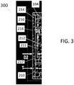
- FIG. 3 is a partial, cross-sectional view showing an exemplary configuration of components at a distal end of an endoscope 300.
- the endoscope 300 in FIG. 3 is similar in some ways to the endoscope 100 represented in FIG. 1 .
- the endoscope 300 in FIG. 3 has a cannula 104 for inserting into a patient's body.
- a translucent or transparent cover 214 extends over a distal end of the cannula 104.
- the cover 214 has a flat outer surface 216 and a flat inner surface 217 (opposite the outer surface).
- Each light source 210 is in direct physical contact with the cover 214, and is configured to deliver light into the cover 214, some of which passes through the cover 214 to illuminate an inspection site inside the patient's body.
- An imaging system 212 (with an optical component/imaging optics 211) is inside the cannula 104 as well.
- the imagining system 212 is configured to receive light (through its optical element 211, for example) that has been reflected off the inspection site in the patient's body and returned to the endoscope through the cover 214.
- the imaging system 212 uses that light to produce one or more images of the inspection site that can be viewed, for example, by a medical professional at a viewing station (e.g., a lens, video screen, or the like).
- each light source 210 delivers light to the distal end of the cannula 104 and into the cover 214.
- a first portion of that light passes through the cover 214 to illuminate an inspection site inside the patient's body, and a second portion of the light passes into the cover 214 and is internally reflected at the outer surface of the cover 214 back toward the inner surface (without ever reaching the inspection site).
- the cover, the light source (and its light cone), and the optical element are configured such that no portion of the light that gets internally reflected at the outer surface of the cover 214 (without ever reaching the inspection site) reaches the optical element 211 or enters the imaging system 212, directly (e.g., without being further reflected inside the cover 214).
- each light source 210 produces a light cone that is 83 degrees
- the cover 214 has a uniform thickness T of 0.3 millimeters
- the distance D1 between each light source 210 and the imaging system 212 or optical element 211 is 0.73 millimeters
- the distal front surface of the imaging system 212 is separated from the inner surface of the cover 214 (with empty space therebetween)
- the distance D2 between the distal front surface of the imaging system 212 and the outer surface of the cover 214 is 0.5 millimeters
- the distal end of each light source 210 is in physical contact with an inner surface of the cover 214.
- the light cone can be between 75 and 91 degrees
- the cover 214 thickness T can be between 0.1 and 0.4 millimeters
- the distance D1 can be between 0.6 and 0.9 millimeters
- the distance D2 can be between 0.3 and 0.6 millimeters.
- the distal ends of the light sources 210 may be separated from (and not in direct contact with) the inner surface of the cover 214.
- one or more of the foregoing dimensions can vary beyond what is specifically mentioned herein, while still producing the result that no portion of the light that gets internally reflected at the outer surface of the cover 214 (without ever reaching the inspection site) does not reach the optical element 211 or enter the imaging system 212, directly (e.g., without being further reflected inside the cover 214).
- the illustrated endoscope has a rigid internal structure 328 that may contact and/or support the light sources 210 and the cover glass.
- This rigid internal structure 328 can be made of, or include, any one of a variety of different materials or combinations of materials.
- the rigid internal structure 328 is a metal.
- the rigid internal structure 328 extends to, and contacts, the cover 214. Moreover, in some implementations, there is an adhesive material between the cover 214 and the portion of the rigid internal structure 328 that contacts the cover 214.
- the rigid internal structure 328 may surround, support, and/or guide the light source(s) 210 through the cannula 104 toward the distal end thereof.
- the cover 214 in the illustrated implementation can be attached to the cannula 104 and/or other components in a variety of different ways.
- the cover 214 secured to the cannula 104 with a soldered connection which may, in some instances, create a seal therebetween that prevents fluids from outside the endoscope from entering the endoscope 300 or reaching the light source(s) 210.
- the cover 214 is configured relative to the light sources 210 and the cannula 104, for example, to ensure that all of the light from the light sources 210 (e.g., in a light cone of 83 degrees) that exits the outer surface of the cover 214 reaches and illuminates the inspection site. In other words, none of the light that exits the outer surface of the cover 214 is blocked by any portion of the endoscope 300 (including the cannula 104).
- FIG. 4 represents another exemplary configuration of components at the distal end of the cannula 104 in FIG. 1 .
- the illustrated figure shows a light source 710 (e.g., a bundle of optical fibers that can carry light) inside the cannula, an imaging system 712 (including, e.g., imaging optics) also inside the cannula, and a single-piece translucent or transparent cover 714 at a distal end of the cannula and that extends over and covers the light source 710 and the imaging system 712.
- a single piece refers generally to the fact that the cover 714 in the illustrated implementation is made from one and only one piece of translucent or transparent material (e.g., glass or plastic) that cannot, for example, easily or predictably be separated into constituent parts and then put back together again.
- the illustrated cover 714 has a first outer surface 716 that is substantially flat and faces an outward direction, and a second inner surface 718 that is opposite the first and that faces an inward direction.
- the figure shows that there are two cavities 720a, 720b in the second surface 718 of the cover 714.
- every cavity 720 in the second surface 718 of the cover 714 is substantially identical in shape and size.
- cavity 720a is substantially identical (in size and shape) to cavity 720b.
- Each cavity 720a, 720b extends through part (in fact, most) of, but not the entire thickness (T1) of the cover 714.
- each cavity 720a, 720b can extend through at least 70%, or at least 80%, or at least 90% of the thickness (T1) of the cover 714.
- Each cavity 720a, 720b has a substantially flat bottom surface 722a, 722b and one or more sidewalls 724a, 724b that extend upward, with a slightly outward flare, from the flat bottom surface 722a, 722b, to define a slightly frustoconical (yet close to cylindrical) space therein.
- Each cavity 720a, 720b is generally configured so that a corresponding one of the light sources (e.g., a bundle of optical fibers 710) can fit into that slightly frustoconical (yet close to cylindrical) space such that the distal ends of the optical fibers can reach, or nearly reach, and be adhered to the bottom surface 722a, 722b of the cavity 720a, 720b (e.g., with an optical adhesive 721 or the like).
- the light sources e.g., a bundle of optical fibers 710
- each of these thin pieces of cover material has a uniform, or at least substantially uniform, thickness across the entirety of the bottom 726a, 726b of each cavity 720a, 720b.
- the rest of the cover 714 has a substantially consistent thickness (T1), with a substantially smooth, flat outer surface 716 and a substantially smooth, flat inner surface, which is part of 718. More specifically, in a typical implementation, there are no cavities anywhere in the substantially smooth, flat outer surface 716 of the cover 714.
- the light source 710 (e.g., a bundle of optical fibers) in the illustrated implementation extends through the cannula all the way up to the cover 714.
- the distal end of the light source 710 extends into cavity 720a such that the distal ends of the optical fibers of the light source 710 either contact (or are very close to) the inner surface of the cover 714 at the bottom 726a of the cavity 720a.
- the distal ends of the optical fibers of light source 710 would be adhered to the inner surface of the bottom 726a of the cavity 720a, with an optical adhesive with a high enough temperature stability.
- each one of the cavities in the cover 714 there is a separate light source (like light source 710) for each one of the cavities in the cover 714.
- a separate light source e.g., a separate bundle of optical fibers
- that separate light source would be arranged and configured relative to cavity 720b in much the same, if not exactly the same, way that light source 710 is arranged relative to cavity 720a.
- the same idea would apply for any other cavities that may be formed in the cover 714.
- the light for each or all of the light sources can originate at the same (or different) remote light generators (e.g., light emitting diodes, lasers, etc.).
- the imaging system 712 in the illustrated implementation extends up to and contacts (or is at least very close to) the cover 714.
- the distal end of the imaging system 712 i.e., the part that is closest to or touching the cover 714) is a window, though which light from the inspection site, for example, can pass.
- the portion of the cover 714 that is in direct physical contact with, or closest to, the imaging system 712 e.g., a window of the imaging system
- the portion of the cover 714 that is in direct physical contact with, or closest to, the imaging system 712 is cavity-free. That is, there are no cavities in any portion of surface 718 that covers the imaging system 712 (or the window of the imaging system 712); instead, the entire portion of the surface 718 of the cover 714 that covers the imaging system 712 is smooth and flat.
- the imaging system 712 in the illustrated implementation, is generally configured so that light (e.g., being reflected back from the inspection site) enters the imaging system 712 through the surface that faces (and that may be in direct physical contact with) the cover 714.
- the optical entrance to the imaging system 712 is separated from the optical output of the light source 710 by a distance D1.
- all (or at least some) of the light sources in the endoscope 100 will be arranged in a symmetrical fashion relative to the imaging system 712.
- all of the optical entrance to the imaging system 712 will separated from the optical output of each light source by the same distance (e.g., D1).
- the light source 710 in the illustrated implementation is configured to deliver light into the inspection site (i.e., the space beyond the cover 714, inside the patient's body) via the portion of the cover 714 that forms the bottom 726a of the cavity 720a.
- Much of the light delivered by the light source 710 which may be in the approximate form of a cone, passes through the bottom 726a of the cavity 720a to illuminate the inspection site, but some of the light may be internally reflected off the outer surface of the cover 714 without exiting the cover 714.
- This first internal reflection causes the first-reflected light to travel back towards the inner surface 718 of the cover 714, where some of that light will pass through the inner surface 718 (into the cannula) and some of that light will, once again, be internally-reflected back toward the front surface of the cover 714.
- the degree to which any of the light delivered by the light source will be internally reflected when it first reaches the outer surface of the cover 714 is generally a function of the cover material, the angle ⁇ at which light is delivered into the cover 714 and, to a lesser degree, the wavelengths included in the light.
- the light will be reflected when it first reaches the outer surface of the cover 714 (i.e., the "first reflex") if the angle of incidence ⁇ is greater than a certain limiting angle, called the critical angle.
- the light source 710, the cover 714 (and its cavity 720a), and the imaging system 712 in the illustrated implementation are configured and arranged so as to ensure that none of the light from that first reflection (i.e., the "first reflex") is able to reach the optical input for the imaging system 712 on that first reflection.
- the "first reflex" light clearly falls short of reaching the optical entrance (i.e., the surface of the imaging system 712 closest to or touching the cover 714.
- the "first reflex" light will not interfere with or limit the capabilities of the imaging system or the endoscope to produce accurate, high resolution images of the inspection site at the system's external viewing device (not shown).
- the illustrated endoscope 100 achieves this outcome (i.e., ensuring that none of the "first reflex" light is able to reach the optical input for the imaging system 712 on the first reflection) in a relatively compact endoscope (i.e., an endoscope with a small outer diameter cannula).
- a relatively compact endoscope i.e., an endoscope with a small outer diameter cannula.
- This is desirable, of course, because any increases in cannula diameter make the endoscope more difficult to use and work with.
- preventing any "first reflex" light from reaching the optical input for the imaging system 712 on the first reflection can be achieved by utilizing a configuration such as the one represented in FIG. 2 without increasing the cannula diameter at all.
- the endoscope's ability to prevent the "first reflex" light in FIG. 2 from reaching the optical entrance to the imaging system 712 may be considered to be a function of: the angle ⁇ at which light is delivered by the light source into the cover 714, the thickness (T1) of the cover 714 from its front surface 716 to the portion of its back surface 718 that contacts (or is closest to) the imaging system 712, the thickness (T2) of the thin portion of the cover 714 in front of the light source 710, and the distance D1 between the optical exit of the light source 710 and the optical entrance of the imaging system 712.
- outer surface 716 of the cover 714 ensures that all of the light (e.g., the entirety of the light cone) that exits the front surface 716 of the cover 714 will reach and end up effectively illuminating the inspection site. More particularly, none of the light that exits the front, outer surface 716 will hit (or be blocked by) any portion of the endoscope 100 including, for example, its cannula 104.
- FIG. 5 is a schematic, cross-sectional view of an endoscope 100, like the one in FIG. 1 , including an electronics housing 102, cannula 104, cable 106 and connector 108.
- the connector 108 which may be connected to an external light source (not shown), an external electrical power source (not shown), and/or an eternal viewing device (not shown), is at one end of the endoscope 100.
- the cable 106 extends from the connector 108 to the electronics housing 102.
- the cable 106 is configured to carry electricity and/or light between the connector 108 and the electronics housing 102.
- Two bundles of optical fibers 210a, 210b extend through the cannula 104 to the distal end of the endoscope 100.
- light travels through the cannula 104 via the optical fiber bundles 210a, 210b and exits the endoscope 100, to illuminate the inspection site, through the cover 214 at the distal end thereof.
- none of the light that exits the endoscope 100 through the cover 214 hits (or is blocked by) any portion of the endoscope 100 including, for example, the outer edges of its cannula 104.
- the imaging system 212 in the illustrated implementation has optics 832 and an optical sensor and printed circuit board 834 (with electronics) associated with the optics 832.
- FIG. 6 is a schematic representation of a light cone being produced by an optical fiber 934, the likes of which may be part of one of the optical fiber bundles (light sources) in endoscope 100.
- the light is shown to be expanding as it passes through the cover 214.
- the fiber diameter in the illustrated implementation is 1 millimeter and the opening angle is approximately 86 degrees.
- the endoscope 100 is configured such that no part of the light cone will be obstructed by any part of the endoscope past the cover 214. More particularly, the upper edge of the light cone emitted by the optical fiber 934 clears the distal end of the cannula 104 by a distance (D clear).
- the endoscope 100 can have a variety of different dimensions. Generally speaking, compactness is considered to be highly desirable with endoscopes.
- the outer diameter of the cover 214 in an exemplary endoscope is approximately 8.3 millimeters. In another example, the outer diameter may be 8.5 millimeters. In yet another example, the outer diameter may be approximately 9 millimeters. This dimension, of course, can vary a bit, but practically speaking, the outer diameter is usually not more than 10 millimeters and usually not less than 8 millimeters. In fact, usually this dimension is mostly between 8 millimeters and 8.5 millimeters or between 8 millimeters and 9 millimeters.
- each light source i.e., the optical fiber bundles
- the distal ends of each light source (i.e., the optical fiber bundles) in an exemplary endoscope are approximately 1.2 millimeters in diameter (of course, this is just an example).
- there are four separate light sources e.g., circular fiber bundles).
- there are two separate light sources approximately half-moon shaped).
- each optical entrance has a diameter of around 2.6 millimeters. But there could also be just one (or more than two).
- the thickness of the cover 214 can vary, of course. In a typical implementation, however, the thicker portions of the cover are between 0.5 millimeters and 1 millimeter. However, in some implementations, the thicker portion could be as low as 0.3 millimeters.
- the thinner portions of the cover 214 are typically between 0.1 millimeters and 0.05 millimeters. In some implementations, the thinner portions of the cover 214 could be as thick as 0.2 millimeters.
- the distance between the optical exit of the light source and the optical entrance of the imaging system is 2 millimeters. However, in various implementations, this dimension can range, for example, between 1 and 4 millimeters.
- FIG. 7 is a partial, schematic, cross-sectional view (taken along 2-2 in FIG. 1 ) showing another exemplary configuration of components at the distal end of the cannula 104 of the endoscope 100.
- the configuration represented in FIG. 7 is similar in many ways to the configuration represented in FIG. 4 .
- the configuration represented in FIG. 7 has a light source 210, an imaging system 212, and a cover 1014.
- the cover 1014 in FIG. 7 is not a single-piece cover; instead, the cover 1014 in FIG. 7 has two pieces 1014, 1014b that may be connected together with an optical adhesive 1014c. More particularly, in the illustrated implementation, the cover 1014 has a first piece 1014 that is thin, yet uniform in thickness, across its entire extent, and a second piece 1014b that is thicker than the first piece 1014, yet still uniform in thickness, across its entire extent.
- the optical adhesive 1014c keeps the second piece 1014b secured to the first piece 1014a.
- the second piece 1014b is substantially centered relative to the first piece 1014a and covers only a portion of the first piece 1014a.
- the size (absolute and relative), shape and configuration of the endoscope and its various implementations can vary considerably.
- other components and subcomponents, not expressly disclosed herein, may be used with or added to the endoscope disclosed herein.
- the disclosure herein can be adapted to various types of endoscope configurations including, for example, stereo endoscopes.
- the concepts including, for example, the covers disclosed herein may be adapted for use in connection with other applications that are not related to endoscopes.
Claims (15)
- Endoscope (100) comprenant :une canule (104) à insérer dans le corps d'un patient ;un et seulement un couvercle (214, 714, 1014) constitué d'un matériau transparent ou translucide qui s'étend sur toute une extrémité distale de la canule (104), le couvercle (214, 714, 1014) ayant une surface extérieure (217, 716) et une surface intérieure (215, 718), opposée à la surface extérieure (217, 716) ;une source de lumière (210, 710) à l'intérieur de la canule (104) conçue pour fournir de la lumière dans le couvercle (214, 714, 1014), dont au moins une partie traverse le couvercle (214, 714, 1014) pour éclairer un site d'inspection à l'intérieur du corps du patient ; etun système d'imagerie (212, 712) à l'intérieur de la canule (104) conçu pour recevoir de la lumière qui a été réfléchie par le site d'inspection dans le corps du patient et renvoyée vers l'endoscope (100) à travers le couvercle (214, 714, 1014) ;dans lequel, pendant le fonctionnement, une partie de la lumière qui est fournie par la source de lumière (210, 710) dans le couvercle (214, 714, 1014) est réfléchie intérieurement au niveau de la surface extérieure (217, 716) du couvercle (214, 714, 1014) pour revenir vers la surface intérieure (215, 718) du couvercle (214, 714, 1014) ;caractérisé en ce qu'une partie du couvercle (214, 714, 1014) devant le système d'imagerie (212, 712) est plus épaisse qu'une partie du couvercle (214, 714, 1014) devant la source de lumière (210, 710) ; etdans lequel la source de lumière (210, 710), le couvercle (214, 714, 1014) et le système d'imagerie (212, 712) sont configurés les uns par rapport aux autres de telle sorte qu'aucune de la lumière qui est réfléchie intérieurement au niveau de la surface extérieure (217, 716) du couvercle (214, 714, 1014) et retourne vers la surface intérieure (215, 718) du couvercle (214, 714, 1014) n'atteint directement une entrée optique du système d'imagerie (212, 712), c'est-à-dire sans être en outre réfléchie intérieurement ; etdans lequel a) un angle auquel la lumière est fournie par la source de lumière (210, 710) dans le couvercle (214, 714, 1014), b) une épaisseur de la partie du couvercle (214, 714, 1014) devant le système d'imagerie (212, 712), c) une épaisseur d'une partie du couvercle (214, 714, 1014) devant la source de lumière (210, 710), et d) une distance entre une sortie optique de la source de lumière (210, 710) et l'entrée optique du système d'imagerie (212, 712) sont conçus pour empêcher la lumière qui est réfléchie intérieurement au niveau de la surface extérieure (217, 716) du couvercle (214, 714, 1014) et retourne vers la surface intérieure (215, 718) du couvercle (214, 714, 1014) d'atteindre une entrée optique du système d'imagerie (212, 712) directement à partir de la réflexion interne.
- Endoscope (100) selon la revendication 1, dans lequel la configuration relative du couvercle (214, 714, 1014), de la source de lumière (210, 710) et du système d'imagerie (212, 712) est seule responsable de la garantie qu'aucune de la lumière qui est réfléchie intérieurement au niveau de la surface extérieure (217, 716) du couvercle (214, 714, 1014) n'atteint directement une entrée optique du système d'imagerie (212, 712).
- Endoscope (100) selon la revendication 2, dans lequel aucune partie du couvercle (214, 714, 1014), à travers laquelle la lumière qui est réfléchie intérieurement au niveau de la surface extérieure (217, 716) du couvercle et retourne vers la surface intérieure (215, 718) du couvercle (214, 714, 1014) se déplace, n'est constituée d'un matériau qui n'est ni translucide ni transparent.
- Endoscope (100) selon l'une quelconque des revendications précédentes, dans lequel le couvercle (214, 714) est formé d'une seule pièce du matériau translucide ou transparent.
- Endoscope (100) selon l'une quelconque des revendications 1 à 3, dans lequel le couvercle (214, 1014) est constitué de deux pièces ou plus (1014a, 1014b) qui sont collées ou autrement fixées les unes aux autres.
- Endoscope (100) selon l'une quelconque des revendications précédentes, dans lequel le couvercle (214, 714, 1014) est accouplé à la canule (104) d'une manière qui empêche les fluides à l'extérieur de l'endoscope (100) d'entrer ou d'atteindre la source de lumière (210, 710), mais permet à toute la lumière provenant de la source de lumière (210, 710) qui sort de la surface extérieure (217, 716) du couvercle (214, 714, 1014) d'atteindre et d'éclairer le site d'inspection.
- Endoscope (100) selon la revendication 6, en outre conçu de telle sorte qu'aucune de la lumière qui sort de la surface extérieure (217, 716) du couvercle (214, 714, 1014) ne frappe ou n'est bloquée par une partie quelconque de l'endoscope (100), y compris la canule (104).
- Endoscope (100) selon l'une quelconque des revendications précédentes, dans lequel la source de lumière (210, 710) comprend un guide de lumière ou un faisceau de fibres optiques conçu pour distribuer la lumière produite par un dispositif de génération de lumière distant.
- Endoscope (100) selon la revendication 8, comprenant en outre :
un adhésif optique entre une extrémité distale du guide de lumière ou du faisceau de fibres optiques et la surface intérieure (215) du couvercle (214, 714, 1014). - Endoscope (100) selon la revendication 1, dans lequel la partie du couvercle (714) devant la source de lumière (710) est conçue pour définir une cavité (720a, 720b) qui fait face à un intérieur de l'endoscope (100).
- Endoscope (100) selon la revendication 10, dans lequel la source de lumière (710) s'étend dans la cavité (720a, 720b).
- Endoscope (100) selon la revendication 11, dans lequel une extrémité distale de la source de lumière (710) est collée à une surface inférieure (722a, 722b) de la cavité (720a, 720b).
- Endoscope (100) selon la revendication 1, dans lequel le couvercle (1014) comprend :une première pièce (1014a) du matériau translucide ou transparent qui est d'épaisseur uniforme sur toute son étendue ;une deuxième pièce (1014b) du matériau translucide ou transparent qui est plus épaisse que la première pièce (1014a), mais toujours d'épaisseur uniforme sur toute son étendue ; etun adhésif optique (1014c) pour fixer la deuxième pièce (1014b) à la première pièce (1014a),dans lequel la deuxième pièce (1014b) est sensiblement centrée par rapport à la première pièce (1014a) et ne recouvre qu'une partie de la première pièce (1014a).
- Endoscope (100) selon la revendication 13, dans lequel une extrémité distale de la source de lumière (210) est collée à une partie de la première pièce (1014a) de matériau translucide ou transparent qui n'est pas recouverte par la deuxième pièce (1014b) de matériau translucide ou transparent.
- Endoscope (100) selon l'une quelconque des revendications précédentes, dans lequel le couvercle (214, 714, 1014) est accouplé à la canule (104) via une connexion soudée.
Applications Claiming Priority (2)
| Application Number | Priority Date | Filing Date | Title |
|---|---|---|---|
| US201762467908P | 2017-03-07 | 2017-03-07 | |
| PCT/US2018/021250 WO2018165229A1 (fr) | 2017-03-07 | 2018-03-07 | Endoscope doté d'un couvercle à l'extrémité distale d'une canule |
Publications (2)
| Publication Number | Publication Date |
|---|---|
| EP3592198A1 EP3592198A1 (fr) | 2020-01-15 |
| EP3592198B1 true EP3592198B1 (fr) | 2021-06-02 |
Family
ID=61802375
Family Applications (1)
| Application Number | Title | Priority Date | Filing Date |
|---|---|---|---|
| EP18714105.6A Active EP3592198B1 (fr) | 2017-03-07 | 2018-03-07 | Endoscope doté d'un couvercle à l'extrémité distale d'une canule |
Country Status (6)
| Country | Link |
|---|---|
| US (1) | US11478128B2 (fr) |
| EP (1) | EP3592198B1 (fr) |
| JP (1) | JP7128198B2 (fr) |
| CN (1) | CN110612054A (fr) |
| CA (1) | CA3055802A1 (fr) |
| WO (1) | WO2018165229A1 (fr) |
Families Citing this family (3)
| Publication number | Priority date | Publication date | Assignee | Title |
|---|---|---|---|---|
| CN110325098A (zh) | 2016-11-28 | 2019-10-11 | 适内有限责任公司 | 具有可分离一次性轴的内窥镜 |
| USD1018844S1 (en) | 2020-01-09 | 2024-03-19 | Adaptivendo Llc | Endoscope handle |
| JP2023168944A (ja) * | 2022-05-16 | 2023-11-29 | Hoya株式会社 | 内視鏡 |
Family Cites Families (22)
| Publication number | Priority date | Publication date | Assignee | Title |
|---|---|---|---|---|
| JPH0623811B2 (ja) | 1988-07-22 | 1994-03-30 | 旭光学工業株式会社 | 内視鏡の先端部 |
| US4942867A (en) * | 1988-07-13 | 1990-07-24 | Asahi Kogaku Kogyo K.K. | Distal end part of endoscope |
| JP3012373B2 (ja) * | 1991-06-05 | 2000-02-21 | 旭光学工業株式会社 | 内視鏡の先端部 |
| JPH09197292A (ja) | 1996-01-12 | 1997-07-31 | Furukawa Electric Co Ltd:The | パイプカメラの頭部 |
| JPH09265047A (ja) * | 1996-03-27 | 1997-10-07 | Matsushita Electric Ind Co Ltd | 電子内視鏡装置 |
| US6328691B1 (en) * | 1996-07-26 | 2001-12-11 | Karl Storz Gmbh & Co. Kg | Endoscope with at least one glued and additionally welded end window |
| DE19743431B4 (de) * | 1997-10-01 | 2011-02-17 | Karl Storz Gmbh & Co. Kg | Endoskop mit Verbundfenster |
| JP4359218B2 (ja) | 2000-07-03 | 2009-11-04 | パナソニック株式会社 | 基地局装置および無線通信方法 |
| DE10205735B4 (de) * | 2002-02-12 | 2004-05-06 | Olympus Winter & Ibe Gmbh | Starre Endoskopoptik mit Lichtleiter und Bildleiter überdeckendem Fenster |
| JP4130940B2 (ja) | 2002-06-17 | 2008-08-13 | Hoya株式会社 | 内視鏡の先端部 |
| JP4083484B2 (ja) * | 2002-07-05 | 2008-04-30 | ペンタックス株式会社 | 汚染防止型内視鏡の先端部 |
| JP4135877B2 (ja) | 2002-07-09 | 2008-08-20 | Hoya株式会社 | 内視鏡の先端部 |
| JP4131008B2 (ja) | 2002-07-12 | 2008-08-13 | Hoya株式会社 | 内視鏡の先端部 |
| JP3954491B2 (ja) * | 2002-12-27 | 2007-08-08 | オリンパス株式会社 | 内視鏡 |
| CN2762751Y (zh) * | 2004-12-14 | 2006-03-08 | 姜克让 | 带有一次性鞘套的内窥镜系统 |
| EP2675335B1 (fr) * | 2011-02-16 | 2021-09-29 | The General Hospital Corporation | Coupleur optique pour un endoscope |
| WO2013054753A1 (fr) * | 2011-10-12 | 2013-04-18 | オリンパスメディカルシステムズ株式会社 | Endoscope |
| JP2014066923A (ja) | 2012-09-26 | 2014-04-17 | Olympus Medical Systems Corp | 内視鏡及び内視鏡用ライトガイドファイバ |
| JP2014212835A (ja) * | 2013-04-23 | 2014-11-17 | ショーダテクトロン株式会社 | 内視鏡用フードおよび同内視鏡用フードを備えた内視鏡 |
| GB201309198D0 (en) * | 2013-05-22 | 2013-07-03 | Smiths Medical Int Ltd | Imaging apparatus |
| GB201318919D0 (en) * | 2013-10-25 | 2013-12-11 | Isis Innovation | Compact microscope |
| EP3053506A1 (fr) * | 2015-02-06 | 2016-08-10 | Qioptiq Photonics GmbH & Co. KG | Caméra intravaginale |
-
2018
- 2018-03-07 JP JP2019548570A patent/JP7128198B2/ja active Active
- 2018-03-07 US US16/491,601 patent/US11478128B2/en active Active
- 2018-03-07 WO PCT/US2018/021250 patent/WO2018165229A1/fr unknown
- 2018-03-07 EP EP18714105.6A patent/EP3592198B1/fr active Active
- 2018-03-07 CA CA3055802A patent/CA3055802A1/fr active Pending
- 2018-03-07 CN CN201880030473.2A patent/CN110612054A/zh active Pending
Also Published As
| Publication number | Publication date |
|---|---|
| CA3055802A1 (fr) | 2018-09-13 |
| CN110612054A (zh) | 2019-12-24 |
| JP7128198B2 (ja) | 2022-08-30 |
| US11478128B2 (en) | 2022-10-25 |
| US20200305692A1 (en) | 2020-10-01 |
| JP2020509830A (ja) | 2020-04-02 |
| WO2018165229A1 (fr) | 2018-09-13 |
| EP3592198A1 (fr) | 2020-01-15 |
Similar Documents
| Publication | Publication Date | Title |
|---|---|---|
| EP3207852B1 (fr) | Composant d'extrémité distale de résine pour endoscope | |
| US11382490B2 (en) | Tip part for a vision device | |
| US8913112B2 (en) | Image pickup unit for endoscope | |
| WO2011027594A1 (fr) | Unité de capture d'image | |
| EP3592198B1 (fr) | Endoscope doté d'un couvercle à l'extrémité distale d'une canule | |
| US8419616B2 (en) | Image pickup device with a protection member and an optical reflection member | |
| US11311184B2 (en) | Tip part for a vision device | |
| US11712151B2 (en) | Tip part for a vision device | |
| EP1408813A1 (fr) | Systeme d'endoscope miniature | |
| CN105828689B (zh) | 摄像装置和内窥镜装置 | |
| WO2020201205A1 (fr) | Boîtier destiné à la pointe d'un endoscope à insertion jetable | |
| KR101516318B1 (ko) | 광효율을 개선한 내시경용 광원 모듈 | |
| JP2022008481A (ja) | 内視鏡 | |
| EP3613328B1 (fr) | Partie de pointe pour dispositif de vision | |
| JP6439081B2 (ja) | 内視鏡 | |
| JP2013099469A (ja) | 撮像装置、内視鏡 | |
| JP6671967B2 (ja) | 内視鏡 | |
| JP2018029885A (ja) | 電子スコープ、電子スコープシステムおよびレンズユニット |
Legal Events
| Date | Code | Title | Description |
|---|---|---|---|
| STAA | Information on the status of an ep patent application or granted ep patent |
Free format text: STATUS: UNKNOWN |
|
| STAA | Information on the status of an ep patent application or granted ep patent |
Free format text: STATUS: THE INTERNATIONAL PUBLICATION HAS BEEN MADE |
|
| PUAI | Public reference made under article 153(3) epc to a published international application that has entered the european phase |
Free format text: ORIGINAL CODE: 0009012 |
|
| STAA | Information on the status of an ep patent application or granted ep patent |
Free format text: STATUS: REQUEST FOR EXAMINATION WAS MADE |
|
| 17P | Request for examination filed |
Effective date: 20191007 |
|
| AK | Designated contracting states |
Kind code of ref document: A1 Designated state(s): AL AT BE BG CH CY CZ DE DK EE ES FI FR GB GR HR HU IE IS IT LI LT LU LV MC MK MT NL NO PL PT RO RS SE SI SK SM TR |
|
| AX | Request for extension of the european patent |
Extension state: BA ME |
|
| DAV | Request for validation of the european patent (deleted) | ||
| DAX | Request for extension of the european patent (deleted) | ||
| GRAP | Despatch of communication of intention to grant a patent |
Free format text: ORIGINAL CODE: EPIDOSNIGR1 |
|
| STAA | Information on the status of an ep patent application or granted ep patent |
Free format text: STATUS: GRANT OF PATENT IS INTENDED |
|
| INTG | Intention to grant announced |
Effective date: 20210125 |
|
| GRAS | Grant fee paid |
Free format text: ORIGINAL CODE: EPIDOSNIGR3 |
|
| GRAA | (expected) grant |
Free format text: ORIGINAL CODE: 0009210 |
|
| STAA | Information on the status of an ep patent application or granted ep patent |
Free format text: STATUS: THE PATENT HAS BEEN GRANTED |
|
| REG | Reference to a national code |
Ref country code: CH Ref legal event code: EP |
|
| AK | Designated contracting states |
Kind code of ref document: B1 Designated state(s): AL AT BE BG CH CY CZ DE DK EE ES FI FR GB GR HR HU IE IS IT LI LT LU LV MC MK MT NL NO PL PT RO RS SE SI SK SM TR |
|
| REG | Reference to a national code |
Ref country code: GB Ref legal event code: FG4D |
|
| REG | Reference to a national code |
Ref country code: AT Ref legal event code: REF Ref document number: 1397670 Country of ref document: AT Kind code of ref document: T Effective date: 20210615 |
|
| REG | Reference to a national code |
Ref country code: IE Ref legal event code: FG4D |
|
| REG | Reference to a national code |
Ref country code: DE Ref legal event code: R096 Ref document number: 602018018014 Country of ref document: DE |
|
| REG | Reference to a national code |
Ref country code: LT Ref legal event code: MG9D |
|
| PG25 | Lapsed in a contracting state [announced via postgrant information from national office to epo] |
Ref country code: HR Free format text: LAPSE BECAUSE OF FAILURE TO SUBMIT A TRANSLATION OF THE DESCRIPTION OR TO PAY THE FEE WITHIN THE PRESCRIBED TIME-LIMIT Effective date: 20210602 Ref country code: LT Free format text: LAPSE BECAUSE OF FAILURE TO SUBMIT A TRANSLATION OF THE DESCRIPTION OR TO PAY THE FEE WITHIN THE PRESCRIBED TIME-LIMIT Effective date: 20210602 Ref country code: FI Free format text: LAPSE BECAUSE OF FAILURE TO SUBMIT A TRANSLATION OF THE DESCRIPTION OR TO PAY THE FEE WITHIN THE PRESCRIBED TIME-LIMIT Effective date: 20210602 Ref country code: BG Free format text: LAPSE BECAUSE OF FAILURE TO SUBMIT A TRANSLATION OF THE DESCRIPTION OR TO PAY THE FEE WITHIN THE PRESCRIBED TIME-LIMIT Effective date: 20210902 |
|
| REG | Reference to a national code |
Ref country code: NL Ref legal event code: MP Effective date: 20210602 |
|
| PG25 | Lapsed in a contracting state [announced via postgrant information from national office to epo] |
Ref country code: GR Free format text: LAPSE BECAUSE OF FAILURE TO SUBMIT A TRANSLATION OF THE DESCRIPTION OR TO PAY THE FEE WITHIN THE PRESCRIBED TIME-LIMIT Effective date: 20210903 Ref country code: RS Free format text: LAPSE BECAUSE OF FAILURE TO SUBMIT A TRANSLATION OF THE DESCRIPTION OR TO PAY THE FEE WITHIN THE PRESCRIBED TIME-LIMIT Effective date: 20210602 Ref country code: SE Free format text: LAPSE BECAUSE OF FAILURE TO SUBMIT A TRANSLATION OF THE DESCRIPTION OR TO PAY THE FEE WITHIN THE PRESCRIBED TIME-LIMIT Effective date: 20210602 Ref country code: PL Free format text: LAPSE BECAUSE OF FAILURE TO SUBMIT A TRANSLATION OF THE DESCRIPTION OR TO PAY THE FEE WITHIN THE PRESCRIBED TIME-LIMIT Effective date: 20210602 Ref country code: NO Free format text: LAPSE BECAUSE OF FAILURE TO SUBMIT A TRANSLATION OF THE DESCRIPTION OR TO PAY THE FEE WITHIN THE PRESCRIBED TIME-LIMIT Effective date: 20210902 Ref country code: LV Free format text: LAPSE BECAUSE OF FAILURE TO SUBMIT A TRANSLATION OF THE DESCRIPTION OR TO PAY THE FEE WITHIN THE PRESCRIBED TIME-LIMIT Effective date: 20210602 |
|
| PG25 | Lapsed in a contracting state [announced via postgrant information from national office to epo] |
Ref country code: RO Free format text: LAPSE BECAUSE OF FAILURE TO SUBMIT A TRANSLATION OF THE DESCRIPTION OR TO PAY THE FEE WITHIN THE PRESCRIBED TIME-LIMIT Effective date: 20210602 Ref country code: NL Free format text: LAPSE BECAUSE OF FAILURE TO SUBMIT A TRANSLATION OF THE DESCRIPTION OR TO PAY THE FEE WITHIN THE PRESCRIBED TIME-LIMIT Effective date: 20210602 Ref country code: PT Free format text: LAPSE BECAUSE OF FAILURE TO SUBMIT A TRANSLATION OF THE DESCRIPTION OR TO PAY THE FEE WITHIN THE PRESCRIBED TIME-LIMIT Effective date: 20211004 Ref country code: CZ Free format text: LAPSE BECAUSE OF FAILURE TO SUBMIT A TRANSLATION OF THE DESCRIPTION OR TO PAY THE FEE WITHIN THE PRESCRIBED TIME-LIMIT Effective date: 20210602 Ref country code: SK Free format text: LAPSE BECAUSE OF FAILURE TO SUBMIT A TRANSLATION OF THE DESCRIPTION OR TO PAY THE FEE WITHIN THE PRESCRIBED TIME-LIMIT Effective date: 20210602 Ref country code: SM Free format text: LAPSE BECAUSE OF FAILURE TO SUBMIT A TRANSLATION OF THE DESCRIPTION OR TO PAY THE FEE WITHIN THE PRESCRIBED TIME-LIMIT Effective date: 20210602 Ref country code: EE Free format text: LAPSE BECAUSE OF FAILURE TO SUBMIT A TRANSLATION OF THE DESCRIPTION OR TO PAY THE FEE WITHIN THE PRESCRIBED TIME-LIMIT Effective date: 20210602 Ref country code: ES Free format text: LAPSE BECAUSE OF FAILURE TO SUBMIT A TRANSLATION OF THE DESCRIPTION OR TO PAY THE FEE WITHIN THE PRESCRIBED TIME-LIMIT Effective date: 20210602 |
|
| REG | Reference to a national code |
Ref country code: AT Ref legal event code: UEP Ref document number: 1397670 Country of ref document: AT Kind code of ref document: T Effective date: 20210602 |
|
| REG | Reference to a national code |
Ref country code: DE Ref legal event code: R097 Ref document number: 602018018014 Country of ref document: DE |
|
| PLBE | No opposition filed within time limit |
Free format text: ORIGINAL CODE: 0009261 |
|
| STAA | Information on the status of an ep patent application or granted ep patent |
Free format text: STATUS: NO OPPOSITION FILED WITHIN TIME LIMIT |
|
| PG25 | Lapsed in a contracting state [announced via postgrant information from national office to epo] |
Ref country code: DK Free format text: LAPSE BECAUSE OF FAILURE TO SUBMIT A TRANSLATION OF THE DESCRIPTION OR TO PAY THE FEE WITHIN THE PRESCRIBED TIME-LIMIT Effective date: 20210602 |
|
| 26N | No opposition filed |
Effective date: 20220303 |
|
| PG25 | Lapsed in a contracting state [announced via postgrant information from national office to epo] |
Ref country code: AL Free format text: LAPSE BECAUSE OF FAILURE TO SUBMIT A TRANSLATION OF THE DESCRIPTION OR TO PAY THE FEE WITHIN THE PRESCRIBED TIME-LIMIT Effective date: 20210602 |
|
| PG25 | Lapsed in a contracting state [announced via postgrant information from national office to epo] |
Ref country code: MC Free format text: LAPSE BECAUSE OF FAILURE TO SUBMIT A TRANSLATION OF THE DESCRIPTION OR TO PAY THE FEE WITHIN THE PRESCRIBED TIME-LIMIT Effective date: 20210602 |
|
| REG | Reference to a national code |
Ref country code: BE Ref legal event code: MM Effective date: 20220331 |
|
| PG25 | Lapsed in a contracting state [announced via postgrant information from national office to epo] |
Ref country code: LU Free format text: LAPSE BECAUSE OF NON-PAYMENT OF DUE FEES Effective date: 20220307 Ref country code: IE Free format text: LAPSE BECAUSE OF NON-PAYMENT OF DUE FEES Effective date: 20220307 |
|
| PG25 | Lapsed in a contracting state [announced via postgrant information from national office to epo] |
Ref country code: BE Free format text: LAPSE BECAUSE OF NON-PAYMENT OF DUE FEES Effective date: 20220331 |
|
| PGFP | Annual fee paid to national office [announced via postgrant information from national office to epo] |
Ref country code: FR Payment date: 20230327 Year of fee payment: 6 Ref country code: AT Payment date: 20230221 Year of fee payment: 6 |
|
| PGFP | Annual fee paid to national office [announced via postgrant information from national office to epo] |
Ref country code: IT Payment date: 20230321 Year of fee payment: 6 |
|
| P01 | Opt-out of the competence of the unified patent court (upc) registered |
Effective date: 20230519 |
|
| PGFP | Annual fee paid to national office [announced via postgrant information from national office to epo] |
Ref country code: CH Payment date: 20230402 Year of fee payment: 6 |
|
| PGFP | Annual fee paid to national office [announced via postgrant information from national office to epo] |
Ref country code: AT Payment date: 20240221 Year of fee payment: 7 |
|
| PG25 | Lapsed in a contracting state [announced via postgrant information from national office to epo] |
Ref country code: MK Free format text: LAPSE BECAUSE OF FAILURE TO SUBMIT A TRANSLATION OF THE DESCRIPTION OR TO PAY THE FEE WITHIN THE PRESCRIBED TIME-LIMIT Effective date: 20210602 Ref country code: CY Free format text: LAPSE BECAUSE OF FAILURE TO SUBMIT A TRANSLATION OF THE DESCRIPTION OR TO PAY THE FEE WITHIN THE PRESCRIBED TIME-LIMIT Effective date: 20210602 |
|
| PGFP | Annual fee paid to national office [announced via postgrant information from national office to epo] |
Ref country code: DE Payment date: 20240327 Year of fee payment: 7 Ref country code: GB Payment date: 20240327 Year of fee payment: 7 |