EP3053506A1 - Caméra intravaginale - Google Patents
Caméra intravaginale Download PDFInfo
- Publication number
- EP3053506A1 EP3053506A1 EP15154180.2A EP15154180A EP3053506A1 EP 3053506 A1 EP3053506 A1 EP 3053506A1 EP 15154180 A EP15154180 A EP 15154180A EP 3053506 A1 EP3053506 A1 EP 3053506A1
- Authority
- EP
- European Patent Office
- Prior art keywords
- imaging device
- elongated housing
- intravaginal
- distal end
- image
- Prior art date
- Legal status (The legal status is an assumption and is not a legal conclusion. Google has not performed a legal analysis and makes no representation as to the accuracy of the status listed.)
- Withdrawn
Links
Images

Classifications
-
- A—HUMAN NECESSITIES
- A61—MEDICAL OR VETERINARY SCIENCE; HYGIENE
- A61B—DIAGNOSIS; SURGERY; IDENTIFICATION
- A61B1/00—Instruments for performing medical examinations of the interior of cavities or tubes of the body by visual or photographical inspection, e.g. endoscopes; Illuminating arrangements therefor
- A61B1/303—Instruments for performing medical examinations of the interior of cavities or tubes of the body by visual or photographical inspection, e.g. endoscopes; Illuminating arrangements therefor for the vagina, i.e. vaginoscopes
-
- A—HUMAN NECESSITIES
- A61—MEDICAL OR VETERINARY SCIENCE; HYGIENE
- A61B—DIAGNOSIS; SURGERY; IDENTIFICATION
- A61B1/00—Instruments for performing medical examinations of the interior of cavities or tubes of the body by visual or photographical inspection, e.g. endoscopes; Illuminating arrangements therefor
- A61B1/00064—Constructional details of the endoscope body
- A61B1/00071—Insertion part of the endoscope body
- A61B1/0008—Insertion part of the endoscope body characterised by distal tip features
- A61B1/00082—Balloons
-
- A—HUMAN NECESSITIES
- A61—MEDICAL OR VETERINARY SCIENCE; HYGIENE
- A61B—DIAGNOSIS; SURGERY; IDENTIFICATION
- A61B1/00—Instruments for performing medical examinations of the interior of cavities or tubes of the body by visual or photographical inspection, e.g. endoscopes; Illuminating arrangements therefor
- A61B1/00064—Constructional details of the endoscope body
- A61B1/00071—Insertion part of the endoscope body
- A61B1/0008—Insertion part of the endoscope body characterised by distal tip features
- A61B1/00089—Hoods
-
- A—HUMAN NECESSITIES
- A61—MEDICAL OR VETERINARY SCIENCE; HYGIENE
- A61B—DIAGNOSIS; SURGERY; IDENTIFICATION
- A61B1/00—Instruments for performing medical examinations of the interior of cavities or tubes of the body by visual or photographical inspection, e.g. endoscopes; Illuminating arrangements therefor
- A61B1/00064—Constructional details of the endoscope body
- A61B1/00071—Insertion part of the endoscope body
- A61B1/0008—Insertion part of the endoscope body characterised by distal tip features
- A61B1/00101—Insertion part of the endoscope body characterised by distal tip features the distal tip features being detachable
-
- A—HUMAN NECESSITIES
- A61—MEDICAL OR VETERINARY SCIENCE; HYGIENE
- A61B—DIAGNOSIS; SURGERY; IDENTIFICATION
- A61B1/00—Instruments for performing medical examinations of the interior of cavities or tubes of the body by visual or photographical inspection, e.g. endoscopes; Illuminating arrangements therefor
- A61B1/04—Instruments for performing medical examinations of the interior of cavities or tubes of the body by visual or photographical inspection, e.g. endoscopes; Illuminating arrangements therefor combined with photographic or television appliances
- A61B1/05—Instruments for performing medical examinations of the interior of cavities or tubes of the body by visual or photographical inspection, e.g. endoscopes; Illuminating arrangements therefor combined with photographic or television appliances characterised by the image sensor, e.g. camera, being in the distal end portion
-
- A—HUMAN NECESSITIES
- A61—MEDICAL OR VETERINARY SCIENCE; HYGIENE
- A61B—DIAGNOSIS; SURGERY; IDENTIFICATION
- A61B1/00—Instruments for performing medical examinations of the interior of cavities or tubes of the body by visual or photographical inspection, e.g. endoscopes; Illuminating arrangements therefor
- A61B1/06—Instruments for performing medical examinations of the interior of cavities or tubes of the body by visual or photographical inspection, e.g. endoscopes; Illuminating arrangements therefor with illuminating arrangements
- A61B1/0661—Endoscope light sources
- A61B1/0684—Endoscope light sources using light emitting diodes [LED]
-
- A—HUMAN NECESSITIES
- A61—MEDICAL OR VETERINARY SCIENCE; HYGIENE
- A61B—DIAGNOSIS; SURGERY; IDENTIFICATION
- A61B1/00—Instruments for performing medical examinations of the interior of cavities or tubes of the body by visual or photographical inspection, e.g. endoscopes; Illuminating arrangements therefor
- A61B1/32—Devices for opening or enlarging the visual field, e.g. of a tube of the body
-
- A—HUMAN NECESSITIES
- A61—MEDICAL OR VETERINARY SCIENCE; HYGIENE
- A61B—DIAGNOSIS; SURGERY; IDENTIFICATION
- A61B5/00—Measuring for diagnostic purposes; Identification of persons
- A61B5/05—Detecting, measuring or recording for diagnosis by means of electric currents or magnetic fields; Measuring using microwaves or radio waves
- A61B5/055—Detecting, measuring or recording for diagnosis by means of electric currents or magnetic fields; Measuring using microwaves or radio waves involving electronic [EMR] or nuclear [NMR] magnetic resonance, e.g. magnetic resonance imaging
-
- A—HUMAN NECESSITIES
- A61—MEDICAL OR VETERINARY SCIENCE; HYGIENE
- A61B—DIAGNOSIS; SURGERY; IDENTIFICATION
- A61B6/00—Apparatus for radiation diagnosis, e.g. combined with radiation therapy equipment
- A61B6/02—Devices for diagnosis sequentially in different planes; Stereoscopic radiation diagnosis
- A61B6/03—Computerised tomographs
- A61B6/032—Transmission computed tomography [CT]
-
- A—HUMAN NECESSITIES
- A61—MEDICAL OR VETERINARY SCIENCE; HYGIENE
- A61B—DIAGNOSIS; SURGERY; IDENTIFICATION
- A61B8/00—Diagnosis using ultrasonic, sonic or infrasonic waves
- A61B8/13—Tomography
-
- A—HUMAN NECESSITIES
- A61—MEDICAL OR VETERINARY SCIENCE; HYGIENE
- A61B—DIAGNOSIS; SURGERY; IDENTIFICATION
- A61B1/00—Instruments for performing medical examinations of the interior of cavities or tubes of the body by visual or photographical inspection, e.g. endoscopes; Illuminating arrangements therefor
- A61B1/00163—Optical arrangements
- A61B1/00188—Optical arrangements with focusing or zooming features
- A61B1/0019—Optical arrangements with focusing or zooming features characterised by variable lenses
Definitions
- the present invention relates to medical imaging, and more particularly, is related to an intravaginal camera.
- Colposcopy is a medical diagnostic procedure to examine an illuminated, magnified view of the cervix and the tissues o f the vagina and vulva.
- Inspection of the cervix has generally been performed by insertion of medical devices inside in the vagina.
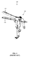
- the medical devices such as a speculum 100, as shown in FIG. 1 , separate the soft tissue of the vaginal walls and provide a direct optical path to the cervix for an external optical device, such as a colposcope.
- the speculum 100 also provides a path for an external light source to illuminate the cervix.
- a speculum 100 has undesirable qualities, such as excessive expansion of the vagina wall throughout the entire length of the vagina, rather than just in the vicinity of the cervix. The result is unnecessary deformation of the vagina and cervix region, as well as unnecessary discomfort for the patient.
- the colposcope and additional standalone examination unit are expensive, and may not be practically used in combination with other diagnostic tools, such as ultrasound systems.
- NA optical aperture NA
- DOF depth of field
- a liquid lens camera for example, an intraoral camera as disclosed in patent applications such as EP 2161607 A1 , EP 1780757 A1 , and PCT/CN2008/001900 , generally includes a first liquid and a second liquid of equal density sandwiched between two transparent windows in a conical vessel.
- the first liquid is generally conductive, while the second liquid is generally insulating.
- a variable voltage can be selectively applied to electrodes in electrical communication with the conductive liquid.
- the interface between the first and second liquid changes its shape depending on the voltage applied across the conical structure. In this way, the liquid lens can attain the desired refraction power by means of changing the voltage applied on the electrodes.
- Embodiments of the present invention provide an intravaginal camera.
- the present invention is directed to an intravaginal imaging device.
- the imaging device is housed within an elongated housing having a proximal end and a distal end.
- the distal end includes a sealing endcap window, an objective disposed behind the window having an auto focus mechanism configured to focus on a target, an image detector disposed behind the objective configured to detect an image from the objective, and a light source configured to illuminate the target.
- a connecting portion in communication with the image detector is disposed at the proximal end.
- the imaging device includes attachment means configured to attach a substantially ring shaped vagina expander to the distal end of the elongated housing.
- the connecting portion is configured to convey an image from the image detector to an external device.
- Exemplary embodiments of an intravaginal camera are intended to perform intravaginal acquisition, cervix acquisition, and the like. It is therefore desirable for a lens module of the camera to have a large depth of field (DOF) and wide field of view (FOV) in a large range of working distances, for example, from under 1 mm to infinity.
- DOF depth of field
- FOV wide field of view
- the camera may be used in a large working distance range with a big DOF.
- the intravaginal camera may focus at a far distance, for example, when positioned at the entrance of the vagina, or at a near distance, for example, when positioned adjacent to the cervix. Focus adjustment is used to provide appropriate image quality.
- a first embodiment of an intravaginal camera includes a housing enclosing an illumination system, a lens system, attachment means for a vagina expander, and electrical components.
- the illumination system is used to provide enough light to illuminate the cervix and vagina interior.
- Polarized illumination may be used to limit reflections.
- one or more white light emitting diodes (LEDs) may be used in the illumination system, which may be preferable due to small size, long lifetime and high luminous flux.
- illumination in one or more specific wavelengths or bands of wavelengths may be used to directly or indirectly illuminate the target, for example via a fluorescence effect.
- the illumination system may include LEDs with different colors, such as red/green/blue or other color combinations in order to produce a better tissue image, or to highlight or discern certain features in the image.
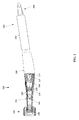
- the elongated housing 206 houses optics and electronics.
- the optics may include a series of fixed lens groups 240, 241, 242 which map a target object (not shown), such as the cervix of a patient, on an image detector 207.
- the fixed lens groups 240, 241, 242 may be formed of optical glass.
- one or more of the fixed lens groups 240, 241, 242 may be formed of sapphire, or other appropriate materials. While three fixed lens groups are shown in the first embodiment, alternative embodiments may include one, two, four or more fixed lens groups.
- the fixed lens groups 240, 241, and 242 are positioned between the target object (not shown) and the image detector 207.
- the first fixed lens group 240 is located behind an ingress window 238 ( FIG. 3 ) at the distal end 205 of the elongated housing 206.
- the first fixed lens group 240 conveys an image to a second fixed lens group 241.
- the second fixed lens group 241 and the third fixed lens group 242 transmit the image to the image detector 207.
- each of the three fixed lens groups 240, 241, 242 has two fixed lenses.
- each fixed lens group may include, one, two, three or more lenses.
- variable lens 208 is positioned between the second fixed lens 241 and the third fixed lens 242.
- the variable lens 208 may be positioned elsewhere with respect to the fixed lens groups, such as behind the third lens group 242.
- the liquid lens is preferably located near the aperture 210.
- the variable lens 208 under the first embodiment is a liquid lens.
- other variable lenses are possible in alternative embodiments.
- one or more conventional solid lenses may be configured to be movable along an optical axis of the distal end 205 of the elongated housing 206, behaving as a classical focusing system.
- the fixed lens groups 240, 241, 242, the variable lens 208 and the ingress window 238 share a common optical axis. In general, the illumination provided by the illumination system is aligned with the common optical axis.
- the imaging characteristics of the variable liquid lens 208 are controllable with electrical voltage as provided to electrodes (not shown) via an electrical lead 209 from an electrical controller 211.
- the electrical controller 211 may be housed within the elongated housing 206, as shown, or may be external to the elongated housing in alternative embodiments.
- the elongated housing 206 of the intravaginal camera 200 includes a variable aperture 210, the diameter of which is adjustable in a specified ratio to the focal position.
- the variable aperture 210 may be implemented as a liquid crystal panel (LCD), which is controlled by a further electrical voltage via an additional electrical connection (not shown). In alternative embodiments a mechanical aperture may be used.
- the image detector 207 may be trained with the controller 211 to control the image sharpness.
- the controller 211 may further control the voltage for the variable liquid lens 208 via the electrical lead 209.
- the processor may be implemented as a computer, as described further below.
- An image at the image detector 207 may further include a scale configured to indicate a size of a region of interest. For example, a scale may be blended with the image at the image detector 207, or the controller 211 may superimpose upon the image of the image detector.
- the scale may be faded into the image at a desired intensity.
- a sheath 260 may surround the proximal end 204 of the elongated housing 206.
- the center axis of the proximal end 204 of the elongated housing 206 may not be aligned with the center axis of the distal end 205 of the elongated housing 206.
- merely rotating the proximal end 204 around its axis outside the vagina may reposition the distal end 205 near the cervix, for example, allowing the user to more easily locate the portio of the cervix.
- a connecting portion 290 may be located at the proximal end 204 of the elongated housing.
- the connecting portion may provide physical connections, for example, electrical connections and or gas/fluid connections, for example, for expanding/deflating the vagina expander 310 ( FIG. 3 ).
- the connecting portion may further include means for wireless connection, for example, WiFi or BlueTooth wireless connections.
- the elongated housing 206 may be formed of a biocompatible plastic, such as a medical grade biocompatible plastic. Alternatively, other materials may be used for the housing that are suitable for sterilization, such as, but not limited to silicone, latex, or metal such as medical grade titanium.
- the elongated housing 206 is approximately 293mm in length, has a maximum diameter of approximately 25.7mm, and a minimum diameter at the distal end 205 of approximately 12.7mm (without the vagina expander 310).
- these dimensions are provided as a non-limiting example, and dimensions of alternative embodiments may vary significantly.
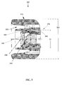
- FIG. 3 shows a detail 300 of the distal end 205 of the elongated housing 206.
- a transparent ingress window 238 may serve as an end cap to the distal end 205 of the elongated housing 206, providing both an optical ingress into the camera 200, as well as a fluid seal to the interior of the camera 200.
- Illumination means 345 such as one or more white LEDs may be disposed behind the ingress window 238 to provide illumination to the target of the camera 200. The illumination levels of the illumination means 345 may be controlled by the electrical controller 211 located within the elongated housing 206 or a remote controller (not shown) located remotely to the elongated housing 206.
- a vagina expander 310 may be removably fastened to the distal end 205 of the elongated housing 206.
- the vagina expander 310 may be configured as a generally ring shaped tube structure substantially surrounding the distal end 205 of the distal end 205 of the elongated housing 206, such that the soft tissue is held apart to allow a clear field of view in front of the distal end 205 of the elongated housing 206.
- the optical path of the intravaginal camera 200 passes through an aperture in the vagina expander 310.
- the vagina expander 310 may be removably attached to the distal end 205 of the elongated housing 206 by one or more of several attachment means 335, for example, a threaded attachment, a tongue in groove attachment, a friction fit attachment where the vagina expander is attached by friction to an otherwise smooth external surface of the distal end 205 of the elongated housing 206, or other means familiar to persons having ordinary skill in the art.
- the attachment means 335 are generally disposed at an inner diameter D1 of the vagina expander, and mate with corresponding means at or near the distal end 205 of the elongated housing 206, in particular, around an outer diameter at or near of the distal end 205 of the elongated housing 206.
- the vagina expander 310 includes a mucus trap 330, formed as a recessed region in a forward facing portion of the vagina expander.
- the mucus trap 330 may extend entirely around the distal end 205 of the elongated housing 206, such that mucus collects within the recess rather than collecting in front of the ingress window 230, thereby keeping the optical and/or illumination path of the intravaginal camera 200 unobstructed and unobscured.
- the interior diameter DI is substantially the same, being configured to mate to the distal end 205 of the elongated housing 206.
- the vagina expander 310 may have differently sized outer diameters DO, for example, but not limited to in the range of 10 mm up to 50 mm.
- the intravaginal camera 200 distal end 205 of the elongated housing 206 includes means for connecting to an optional vagina expander 310
- the intravaginal camera 200 may be operated without a vagina expander 310.
- the intravaginal camera 200 may be used in conjunction with a speculum 100 ( FIG. 1 ), where the intravaginal camera 200 is inserted within the jaws 150 ( FIG. 1 ) of the speculum 100 ( FIG. 1 ), and then positioned within the spacers 110, 120 ( FIG. 1 ) as needed to obtain access to the desired target, for example, the cervix.
- the intravaginal camera 200 is preferably not attached to the speculum 100 ( FIG. 1 ), but rather used independently. Therefore, the use of the term "vagina expander" within this disclosure and the claims should not be interpreted to mean a speculum.
- the intravaginal camera 200 may be used in combination with a speculum 100 using a suitable holder provided by the speculum 100 or/and intravaginal camera 200 so as to affix the intravaginal camera 200 to the speculum 100, or provide a movable connection so that the intravaginal camera 200 is moveable along the speculum, for example, along a rail or slot.
- the intravaginal camera 200 may include a variably sized vagina expander 310.
- the intravaginal camera 200 may include means for expanding or contracting the outer diameter DO of the vagina expander 310.
- expansion/contraction means may include inflation/deflation of gasses and/or fluids in an expanding/contracting tube within the vagina expander 310. Control of the amount of expansion/contraction may be controlled by the controller 211 located within the housing 206, or external to the housing 206.
- the vagina expander 310 may be implemented as a disposable or cleanable tube or cover pulled over the elongated housing 206.
- the controller 211 ( FIG. 2 ) for executing the functionality described in detail above may be a computer, an example of which is shown in the schematic diagram of FIG. 5.
- Such functionality may be related to the systems described above, for example, the illumination System, the focus or autofocus system, the auto-inflation system, and other such systems that may be electronically controlled.
- the system 500 contains a processor 502, a storage device 504, a memory 506 having software 508 stored therein that defines the abovementioned functionality, input and output (I/O) devices 510 (or peripherals), and a local bus, or local interface 512 allowing for communication within the system 500.
- I/O input and output
- the local interface 512 can be, for example but not limited to, one or more buses or other wired or wireless connections, as is known in the art.
- the local interface 512 may have additional elements, which are omitted for simplicity, such as controllers, buffers (caches), drivers, repeaters, and receivers, to enable communications. Further, the local interface 512 may include address, control, and/or data connections to enable appropriate communications among the aforementioned components.
- the processor 502 is a hardware device for executing software, particularly that stored in the memory 506.
- the processor 502 can be any custom made or commercially available single core or multi-core processor, a central processing unit (CPU), an auxiliary processor among several processors associated with the present system 500, a semiconductor based microprocessor (in the form of a microchip or chip set), a macroprocessor, or generally any device for executing software instructions.
- the memory 506 can include any one or combination of volatile memory elements (e.g., random access memory (RAM, such as DRAM, SRAM, SDRAM, etc .)) and nonvolatile memory elements (e.g., ROM, hard drive, tape, CDROM, etc.). Moreover, the memory 506 may incorporate electronic, magnetic, optical, and/or other types of storage media. Note that the memory 506 can have a distributed architecture, where various components are situated remotely from one another, but can be accessed by the processor 502.
- the software 508 defines functionality performed by the system 500, in accordance with the present invention.
- the software 508 in the memory 506 may include one or more separate programs, each of which contains an ordered listing of executable instructions for implementing logical functions of the system 500, as described below.
- the memory 506 may contain an operating system (O/S) 520.
- the operating system essentially controls the execution of programs within the system 500 and provides scheduling, input-output control, file and data management, memory management, and communication control and related services.
- the I/O devices 510 may include input devices, for example but not limited to, a keyboard, mouse, scanner, microphone, etc.
- An input device may include a switch or actuator configured to start the autofocus procedure, for example, implemented as a switch on the housing, an external wired or wireless footswitch or by a keyboard, keypad, touchscreen, or other mechanism.
- the I/O devices 510 may also include output devices, for example but not limited to, a display, et cetera, which may be connected via a USB connector, or the illumination means 345 ( FIG. 3 ).
- the I/O devices 510 may further include devices that communicate via both inputs and outputs, for instance but not limited to, a wireless communication system, a radio frequency (RF) or other transceiver, a telephonic interface, a bridge, a router, or other device.
- RF radio frequency
- the processor 502 is configured to execute the software 508 stored within the memory 506, to communicate data to and from the memory 506, and to generally control operations of the system 500 pursuant to the software 508, as explained above.
- the processor 502 When the functionality of the system 500 is in operation, the processor 502 is configured to execute the software 508 stored within the memory 506, to communicate data to and from the memory 506, and to generally control operations of the system 500 pursuant to the software 508.
- the operating system 520 is read by the processor 502, perhaps buffered within the processor 502, and then executed.
- a computer-readable medium for use by or in connection with any computer-related device, system, or method.
- Such a computer-readable medium may, in some embodiments, correspond to either or both the memory 506 or the storage device 504.
- a computer-readable medium is an electronic, magnetic, optical, or other physical device or means that can contain or store a computer program for use by or in connection with a computer-related device, system, or method.
- Instructions for implementing the system can be embodied in any computer-readable medium for use by or in connection with the processor or other such instruction execution system, apparatus, or device.
- such instruction execution system, apparatus, or device may, in some embodiments, be any computer-based system, processor-containing system, or other system that can fetch the instructions from the instruction execution system, apparatus, or device and execute the instructions.
- a "computer-readable medium" can be any means that can store, communicate, propagate, or transport the program for use by or in connection with the processor or other such instruction execution system, apparatus, or device.
- Such a computer-readable medium can be, for example but not limited to, an electronic, magnetic, optical, electromagnetic, infrared, or semiconductor system, apparatus, device, or propagation medium. More specific examples (a nonexhaustive list) of the computer-readable medium would include the following: an electrical connection (electronic) having one or more wires, a portable computer diskette (magnetic), a random access memory (RAM) (electronic), a read-only memory (ROM) (electronic), an erasable programmable read-only memory (EPROM, EEPROM, or Flash memory) (electronic), an optical fiber (optical), and a portable compact disc read-only memory (CDROM) (optical).
- an electrical connection having one or more wires
- a portable computer diskette magnetic
- RAM random access memory
- ROM read-only memory
- EPROM erasable programmable read-only memory
- EPROM erasable programmable read-only memory
- CDROM portable compact disc read-only memory
- the computer-readable medium could even be paper or another suitable medium upon which the program is printed, as the program can be electronically captured, via for instance optical scanning of the paper or other medium, then compiled, interpreted or otherwise processed in a suitable manner if necessary, and then stored in a computer memory.
- system 500 can be implemented with any or a combination of the following technologies, which are each well known in the art: a discreet logic circuit(s) having logic gates for implementing logic functions upon data signals, an application specific integrated circuit (ASIC) having appropriate combinational logic gates, a programmable gate array(s) (PGA), a field programmable gate array (FPGA), etc.
- ASIC application specific integrated circuit
- PGA programmable gate array
- FPGA field programmable gate array
- an intravaginal camera may be used for cervix inspection inside in the vagina with or without a speculum, because of the ergonomic shape including the vagina expander or inflatable bellow. This assists in observing the cervix regarding changes of the cervix mucosa. Advantages include lower costs compared with traditional colposcopy equipment and procedures, and no mandatory usage of a speculum, which is more comfortable and convenient for the patient.
- the intravaginal camera may be used in combination with ultrasound systems, for example via USB interface, providing a direct view and LED illumination on the region of interest (ROI) based on intravaginal use.
- the intravaginal camera may provide a digital image for recording and data transfer.
- the ergonomic shape provides easy handling and avoids contamination of the internal optics.
Priority Applications (5)
| Application Number | Priority Date | Filing Date | Title |
|---|---|---|---|
| EP15154180.2A EP3053506A1 (fr) | 2015-02-06 | 2015-02-06 | Caméra intravaginale |
| KR1020160014163A KR20160097141A (ko) | 2015-02-06 | 2016-02-04 | 질내 촬상 장치, 시스템 및 방법 |
| JP2016019473A JP2016154848A (ja) | 2015-02-06 | 2016-02-04 | 膣内撮像デバイス、システムおよび方法 |
| US15/015,850 US20160227994A1 (en) | 2015-02-06 | 2016-02-04 | Intravaginal Imaging Device, System and Method |
| CN201610082883.4A CN105852793A (zh) | 2015-02-06 | 2016-02-05 | 阴道内成像装置、系统和方法 |
Applications Claiming Priority (1)
| Application Number | Priority Date | Filing Date | Title |
|---|---|---|---|
| EP15154180.2A EP3053506A1 (fr) | 2015-02-06 | 2015-02-06 | Caméra intravaginale |
Publications (1)
| Publication Number | Publication Date |
|---|---|
| EP3053506A1 true EP3053506A1 (fr) | 2016-08-10 |
Family
ID=52450020
Family Applications (1)
| Application Number | Title | Priority Date | Filing Date |
|---|---|---|---|
| EP15154180.2A Withdrawn EP3053506A1 (fr) | 2015-02-06 | 2015-02-06 | Caméra intravaginale |
Country Status (5)
| Country | Link |
|---|---|
| US (1) | US20160227994A1 (fr) |
| EP (1) | EP3053506A1 (fr) |
| JP (1) | JP2016154848A (fr) |
| KR (1) | KR20160097141A (fr) |
| CN (1) | CN105852793A (fr) |
Families Citing this family (9)
| Publication number | Priority date | Publication date | Assignee | Title |
|---|---|---|---|---|
| USD785171S1 (en) * | 2015-12-17 | 2017-04-25 | Bridea Ip Limited | Speculum |
| NL2017733B1 (en) * | 2016-11-07 | 2018-05-23 | Femiscope B V | Vaginal Speculum |
| US11478128B2 (en) * | 2017-03-07 | 2022-10-25 | Qioptiq Photonics Gmbh & Co. Kg | Endoscope with cover at distal end of cannula |
| WO2019070998A1 (fr) | 2017-10-04 | 2019-04-11 | Duke University | Colposcopes, mammoscopes et dispositifs d'insertion ayant des extrémités incurvées et procédés associés |
| EP3787470B1 (fr) * | 2018-05-02 | 2024-01-24 | Stryker Corporation | Mise au point automatique de lentille liquide pour visualisation de chirurgie endoscopique |
| CN108937859A (zh) * | 2018-06-06 | 2018-12-07 | 河南科技大学第附属医院 | 一种用于腹腔镜下子宫肌瘤探测器 |
| CN111297309B (zh) * | 2020-03-07 | 2024-01-30 | 陕西艾诺美瑞申医疗科技有限公司 | 一种医学影像成像用电子内窥镜 |
| KR102481179B1 (ko) * | 2020-12-30 | 2022-12-26 | (주)엔티엘헬스케어 | 빛 반사 감소기술이 적용된 자궁경부 진단 카메라 장치 |
| CN116092656A (zh) * | 2023-03-03 | 2023-05-09 | 铜川市人民医院 | 一种妇科手术检查用阴道扩张装置故障检测方法及系统 |
Citations (6)
| Publication number | Priority date | Publication date | Assignee | Title |
|---|---|---|---|---|
| DE2620173A1 (de) * | 1976-05-07 | 1977-11-10 | Storz Karl | Strahlungsblende |
| US6306081B1 (en) * | 1998-04-21 | 2001-10-23 | Olympus Optical Co., Ltd. | Hood for an endoscope |
| US6896653B1 (en) * | 2002-03-07 | 2005-05-24 | Science For Medical Advocates, Inc. | Personal pelvic viewer |
| EP1780757A2 (fr) | 2005-10-31 | 2007-05-02 | Samsung SDI Co., Ltd. | Vaisseau évacué et appareil d'émission d'électrons |
| EP2161607A1 (fr) | 2005-10-27 | 2010-03-10 | LINOS Photonics GmbH & Co. KG | Caméra dentaire |
| WO2013071153A1 (fr) * | 2011-11-09 | 2013-05-16 | Welch Allyn, Inc. | Dispositifs médicaux à base numérique |
Family Cites Families (17)
| Publication number | Priority date | Publication date | Assignee | Title |
|---|---|---|---|---|
| US4210133A (en) * | 1975-10-21 | 1980-07-01 | Consejo Nacional De Ciencia Y Tecnologia | Vaginal microscope |
| US6624935B2 (en) * | 2000-12-06 | 2003-09-23 | Karl Store Imaging, Inc. | Single-axis stereoscopic video imaging system with centering capability |
| JP2004065316A (ja) * | 2002-08-01 | 2004-03-04 | Olympus Corp | 内視鏡装置 |
| US7297116B2 (en) * | 2003-04-21 | 2007-11-20 | Wisconsin Alumni Research Foundation | Method and apparatus for imaging the cervix and uterine wall |
| CN1795807A (zh) * | 2004-12-24 | 2006-07-05 | 上海雷硕医疗器械有限公司 | 一种人体生殖腔道镜像方向自助观察系统 |
| US8388523B2 (en) * | 2005-04-01 | 2013-03-05 | Welch Allyn, Inc. | Medical diagnostic instrument having portable illuminator |
| US9492240B2 (en) * | 2009-06-16 | 2016-11-15 | Intuitive Surgical Operations, Inc. | Virtual measurement tool for minimally invasive surgery |
| WO2009000078A1 (fr) * | 2007-06-25 | 2008-12-31 | Led Medical Diagnostics, Inc. | Methodes, systemes et appareil pour dispositifs de visualisation a extension de type colposcopiques |
| JP2009297426A (ja) * | 2008-06-17 | 2009-12-24 | Fujinon Corp | 電子内視鏡 |
| US8254023B2 (en) * | 2009-02-23 | 2012-08-28 | Visiongate, Inc. | Optical tomography system with high-speed scanner |
| US20100305406A1 (en) * | 2009-05-26 | 2010-12-02 | Ori Braun | System, device and method for gynecological use |
| US20110190689A1 (en) * | 2009-09-28 | 2011-08-04 | Bennett James D | Intravaginal therapy device |
| US8638995B2 (en) * | 2009-11-10 | 2014-01-28 | Illumigyn Ltd. | Optical speculum |
| CN201585960U (zh) * | 2010-01-22 | 2010-09-22 | 王伟 | 妇科内窥器 |
| CN202051731U (zh) * | 2010-12-30 | 2011-11-30 | 广州宝胆医疗器械科技有限公司 | 一体化彩色多普勒超声电子阴道镜系统 |
| JP6180405B2 (ja) * | 2011-05-03 | 2017-08-16 | エンドーシー コーポレイションEndosee Corporation | ヒステロスコピー及び子宮内膜生検用の方法及び装置 |
| US9393087B2 (en) * | 2013-08-01 | 2016-07-19 | Align Technology, Inc. | Methods and systems for generating color images |
-
2015
- 2015-02-06 EP EP15154180.2A patent/EP3053506A1/fr not_active Withdrawn
-
2016
- 2016-02-04 US US15/015,850 patent/US20160227994A1/en not_active Abandoned
- 2016-02-04 JP JP2016019473A patent/JP2016154848A/ja active Pending
- 2016-02-04 KR KR1020160014163A patent/KR20160097141A/ko not_active Application Discontinuation
- 2016-02-05 CN CN201610082883.4A patent/CN105852793A/zh active Pending
Patent Citations (6)
| Publication number | Priority date | Publication date | Assignee | Title |
|---|---|---|---|---|
| DE2620173A1 (de) * | 1976-05-07 | 1977-11-10 | Storz Karl | Strahlungsblende |
| US6306081B1 (en) * | 1998-04-21 | 2001-10-23 | Olympus Optical Co., Ltd. | Hood for an endoscope |
| US6896653B1 (en) * | 2002-03-07 | 2005-05-24 | Science For Medical Advocates, Inc. | Personal pelvic viewer |
| EP2161607A1 (fr) | 2005-10-27 | 2010-03-10 | LINOS Photonics GmbH & Co. KG | Caméra dentaire |
| EP1780757A2 (fr) | 2005-10-31 | 2007-05-02 | Samsung SDI Co., Ltd. | Vaisseau évacué et appareil d'émission d'électrons |
| WO2013071153A1 (fr) * | 2011-11-09 | 2013-05-16 | Welch Allyn, Inc. | Dispositifs médicaux à base numérique |
Also Published As
| Publication number | Publication date |
|---|---|
| CN105852793A (zh) | 2016-08-17 |
| JP2016154848A (ja) | 2016-09-01 |
| US20160227994A1 (en) | 2016-08-11 |
| KR20160097141A (ko) | 2016-08-17 |
Similar Documents
| Publication | Publication Date | Title |
|---|---|---|
| EP3053506A1 (fr) | Caméra intravaginale | |
| ES2718684T3 (es) | Espéculo óptico | |
| AU2014211763B2 (en) | Method for identifying objects in a subject's ear | |
| US20100016668A1 (en) | Medical device for discreetly performing a routine vaginal examination | |
| CA2897712A1 (fr) | Procede d'identification d'objets dans l'oreille d'un sujet | |
| JP2016154848A5 (fr) | ||
| JP2008515573A (ja) | 観察及び検査を改善するための膣鏡観察チューブに関するシステムおよび方法 | |
| US9271640B2 (en) | Optical speculum | |
| JP6760622B2 (ja) | 内視鏡装置 | |
| WO2017199535A1 (fr) | Système d'observation biologique | |
| US10898069B1 (en) | Optical apparatus | |
| US20230389777A1 (en) | Sterile Calibrating Cap and Methods for Using the Same on an Endoscope | |
| US20240032778A1 (en) | Optical System for Endoscope and Endoscope | |
| JP2018183339A (ja) | 蛍光観察ユニット、観察器具、遮光部材 | |
| JP2016029961A (ja) | 内視鏡装置 | |
| EP2787333A1 (fr) | Dispositif d'inspection d'oreille et procédé de détermination d'une condition de l'oreille d'un sujet | |
| CN117838021A (zh) | 内窥镜镜鞘保护结构 |
Legal Events
| Date | Code | Title | Description |
|---|---|---|---|
| PUAI | Public reference made under article 153(3) epc to a published international application that has entered the european phase |
Free format text: ORIGINAL CODE: 0009012 |
|
| AK | Designated contracting states |
Kind code of ref document: A1 Designated state(s): AL AT BE BG CH CY CZ DE DK EE ES FI FR GB GR HR HU IE IS IT LI LT LU LV MC MK MT NL NO PL PT RO RS SE SI SK SM TR |
|
| AX | Request for extension of the european patent |
Extension state: BA ME |
|
| 17P | Request for examination filed |
Effective date: 20170209 |
|
| RBV | Designated contracting states (corrected) |
Designated state(s): AL AT BE BG CH CY CZ DE DK EE ES FI FR GB GR HR HU IE IS IT LI LT LU LV MC MK MT NL NO PL PT RO RS SE SI SK SM TR |
|
| 17Q | First examination report despatched |
Effective date: 20191113 |
|
| STAA | Information on the status of an ep patent application or granted ep patent |
Free format text: STATUS: EXAMINATION IS IN PROGRESS |
|
| STAA | Information on the status of an ep patent application or granted ep patent |
Free format text: STATUS: THE APPLICATION HAS BEEN WITHDRAWN |
|
| 18W | Application withdrawn |
Effective date: 20210302 |