EP3590853B1 - Bearbeitungsvorrichtung für verpackungsmaschinen - Google Patents
Bearbeitungsvorrichtung für verpackungsmaschinen Download PDFInfo
- Publication number
- EP3590853B1 EP3590853B1 EP19172470.7A EP19172470A EP3590853B1 EP 3590853 B1 EP3590853 B1 EP 3590853B1 EP 19172470 A EP19172470 A EP 19172470A EP 3590853 B1 EP3590853 B1 EP 3590853B1
- Authority
- EP
- European Patent Office
- Prior art keywords
- processing
- packaging machine
- processing units
- accordance
- adjustment
- Prior art date
- Legal status (The legal status is an assumption and is not a legal conclusion. Google has not performed a legal analysis and makes no representation as to the accuracy of the status listed.)
- Active
Links
Images

Classifications
-
- E—FIXED CONSTRUCTIONS
- E03—WATER SUPPLY; SEWERAGE
- E03D—WATER-CLOSETS OR URINALS WITH FLUSHING DEVICES; FLUSHING VALVES THEREFOR
- E03D9/00—Sanitary or other accessories for lavatories ; Devices for cleaning or disinfecting the toilet room or the toilet bowl; Devices for eliminating smells
- E03D9/02—Devices adding a disinfecting, deodorising, or cleaning agent to the water while flushing
- E03D9/03—Devices adding a disinfecting, deodorising, or cleaning agent to the water while flushing consisting of a separate container with an outlet through which the agent is introduced into the flushing water, e.g. by suction ; Devices for agents in direct contact with flushing water
- E03D9/033—Devices placed inside or dispensing into the cistern
-
- B—PERFORMING OPERATIONS; TRANSPORTING
- B65—CONVEYING; PACKING; STORING; HANDLING THIN OR FILAMENTARY MATERIAL
- B65B—MACHINES, APPARATUS OR DEVICES FOR, OR METHODS OF, PACKAGING ARTICLES OR MATERIALS; UNPACKING
- B65B61/00—Auxiliary devices, not otherwise provided for, for operating on sheets, blanks, webs, binding material, containers or packages
- B65B61/02—Auxiliary devices, not otherwise provided for, for operating on sheets, blanks, webs, binding material, containers or packages for perforating, scoring, slitting, or applying code or date marks on material prior to packaging
- B65B61/025—Auxiliary devices, not otherwise provided for, for operating on sheets, blanks, webs, binding material, containers or packages for perforating, scoring, slitting, or applying code or date marks on material prior to packaging for applying, e.g. printing, code or date marks on material prior to packaging
-
- B—PERFORMING OPERATIONS; TRANSPORTING
- B65—CONVEYING; PACKING; STORING; HANDLING THIN OR FILAMENTARY MATERIAL
- B65B—MACHINES, APPARATUS OR DEVICES FOR, OR METHODS OF, PACKAGING ARTICLES OR MATERIALS; UNPACKING
- B65B61/00—Auxiliary devices, not otherwise provided for, for operating on sheets, blanks, webs, binding material, containers or packages
- B65B61/02—Auxiliary devices, not otherwise provided for, for operating on sheets, blanks, webs, binding material, containers or packages for perforating, scoring, slitting, or applying code or date marks on material prior to packaging
-
- E—FIXED CONSTRUCTIONS
- E03—WATER SUPPLY; SEWERAGE
- E03D—WATER-CLOSETS OR URINALS WITH FLUSHING DEVICES; FLUSHING VALVES THEREFOR
- E03D9/00—Sanitary or other accessories for lavatories ; Devices for cleaning or disinfecting the toilet room or the toilet bowl; Devices for eliminating smells
- E03D9/02—Devices adding a disinfecting, deodorising, or cleaning agent to the water while flushing
- E03D9/03—Devices adding a disinfecting, deodorising, or cleaning agent to the water while flushing consisting of a separate container with an outlet through which the agent is introduced into the flushing water, e.g. by suction ; Devices for agents in direct contact with flushing water
- E03D9/033—Devices placed inside or dispensing into the cistern
- E03D9/035—Devices connected to the actuation mechanism
-
- E—FIXED CONSTRUCTIONS
- E03—WATER SUPPLY; SEWERAGE
- E03D—WATER-CLOSETS OR URINALS WITH FLUSHING DEVICES; FLUSHING VALVES THEREFOR
- E03D9/00—Sanitary or other accessories for lavatories ; Devices for cleaning or disinfecting the toilet room or the toilet bowl; Devices for eliminating smells
- E03D9/02—Devices adding a disinfecting, deodorising, or cleaning agent to the water while flushing
- E03D9/03—Devices adding a disinfecting, deodorising, or cleaning agent to the water while flushing consisting of a separate container with an outlet through which the agent is introduced into the flushing water, e.g. by suction ; Devices for agents in direct contact with flushing water
- E03D9/033—Devices placed inside or dispensing into the cistern
- E03D9/037—Active dispensers, i.e. comprising a moving dosing element
-
- E—FIXED CONSTRUCTIONS
- E03—WATER SUPPLY; SEWERAGE
- E03D—WATER-CLOSETS OR URINALS WITH FLUSHING DEVICES; FLUSHING VALVES THEREFOR
- E03D9/00—Sanitary or other accessories for lavatories ; Devices for cleaning or disinfecting the toilet room or the toilet bowl; Devices for eliminating smells
- E03D9/02—Devices adding a disinfecting, deodorising, or cleaning agent to the water while flushing
- E03D2009/028—Devices adding a disinfecting, deodorising, or cleaning agent to the water while flushing using a liquid substance
-
- E—FIXED CONSTRUCTIONS
- E03—WATER SUPPLY; SEWERAGE
- E03D—WATER-CLOSETS OR URINALS WITH FLUSHING DEVICES; FLUSHING VALVES THEREFOR
- E03D9/00—Sanitary or other accessories for lavatories ; Devices for cleaning or disinfecting the toilet room or the toilet bowl; Devices for eliminating smells
- E03D9/02—Devices adding a disinfecting, deodorising, or cleaning agent to the water while flushing
- E03D9/03—Devices adding a disinfecting, deodorising, or cleaning agent to the water while flushing consisting of a separate container with an outlet through which the agent is introduced into the flushing water, e.g. by suction ; Devices for agents in direct contact with flushing water
- E03D9/031—Devices connected to or dispensing into the flushing pipe
Definitions
- the invention relates to a processing device for packaging machines, in particular for labeling and / or printing packaging, with at least one upper processing unit for processing packaging tops and at least one lower processing unit for processing packaging undersides.
- the invention also relates to a packaging machine, in particular for food products, with at least one processing device according to the invention.
- Packaging machines such as are used in particular for packaging food products, typically comprise a multiplicity of work stations which are arranged one after the other along a work or transport direction. In such food processing lines with packaging machines, the products are often not only packaged, but the packs are actually produced in the first place.
- the packs are made from at least two material webs, in particular film webs, namely a so-called lower film and a so-called upper film.
- the lower film is reshaped by means of a deep-drawing process, in order, for example, to produce a shell-shaped lower part of a respective pack.
- the workflow in such a deep-drawing packaging machine is in particular clocked.
- a predetermined length of film is withdrawn and transported along the packaging machine, with one work cycle corresponding to at least one pack or, if the packaging machine is designed with multiple lanes, at least one row of packs lying transversely to the transport direction.
- the packs are provided with labels and / or printed, for example.
- this is often done on the packaging machines themselves, which are provided with appropriate processing devices for this purpose. These are usually arranged at an end region of the packaging machine in order to label or print the finished packs, which are still connected as a film web, for example.
- processing devices such as labelers and printers for packs have been known for a long time.
- the object of the invention is therefore to create a possibility for processing packs on packaging machines, which has the smallest possible space requirement and allows the simplest possible operation.
- a processing device with the features of claim 1.
- a common adjustment axis is provided for the processing units, along which the processing units can be adjusted manually or by means of a drive in an adjustment direction that runs parallel to a transport direction of the packaging machine.
- the object is also achieved by a packaging machine with at least one processing device according to the invention.
- the invention leaves the path taken so far in the prior art, in the case of several processing units, to consider them as separate, independent machines and to design and operate them accordingly, each of which requires a complete separate infrastructure in order to be attached to the packaging machine and in particular in the direction of transport Packaging machine to be adjusted.
- the common adjustment axis is not to be understood as an imaginary or virtual axis in the mathematical sense, but rather an objective component or structural unit that can be adjusted manually or by means of a drive of the processing units parallel to the transport direction of the packaging machine.
- the adjustment axis can be a component or unit, however specifically configured, extending over a suitable adjustment length parallel to the transport direction of the packaging machine, for example a guide rod, whereby this component or unit can consequently also fulfill a guiding function.
- this does not exclude additional guides for the machining units.
- the adjustment axis can form or comprise a common drive element for the processing units or be formed by such a drive element.
- This drive element can be, for example, a spindle, a toothed belt or a toothed rack.
- the concept of the invention makes it possible to shift the operation of all processing units completely to just one of the sides of the packaging machine.
- an additional guide for the processing units can be provided, which, however, does not need to be addressed by the operating personnel, at least while the packaging machine is in operation.
- Another advantage of a common adjustment axis for several processing units is that certain safety-related measures - insofar as they are fundamentally necessary - only need to be taken on one side of the packaging machine.
- the processing units can be adjusted in opposite directions with respect to the transport direction of the packaging machine, a risk of injury to the operating personnel, which is potentially due to this adjustability, must be carried out by means of suitable safety regulations Measures such as the provision of a cover can be avoided.
- the processing units can be adjusted via the central control of the packaging machine or the entire processing line into which the packaging machine is possibly integrated.
- inventive concept enables a variety of work variants, which will be discussed in more detail elsewhere, with at least certain variants not yet being able to be implemented, or at most with the acceptance of a considerable additional working length of the packaging machine.
- a single common adjustment axis can be provided for the machining units.
- At least one further common adjustment axis can be provided, in which case all the common adjustment axes of the processing units are arranged on the same side of the packaging machine.
- An adjustment axis which can also be referred to as the main adjustment axis, can primarily be provided for joint adjustment of the machining units.
- a machining unit that is decoupled from the main adjustment axis can be coupled to a further common adjustment axis and, for example, be brought into a non-working position along this further common adjustment axis, independently of the other machining unit or units.
- a common adjustment axis within the meaning of the invention can also be provided in such a way that one processing unit is not directly connected to the common one Adjusting axis interacts, but only indirectly via the respective other processing unit, which interacts directly with the common adjustment axis.
- the two machining units are consequently not adjustable independently of one another by means of the common adjustment axis.
- this does not preclude the processing units from being movable relative to one another in order, for example, to be able to change an offset in the transport direction of the packaging machine between the two processing units.
- Preferred embodiments can also be found in the following description, the dependent claims and the drawing.
- a common travel drive is provided for the two machining units, with which the machining units can be moved along the adjustment axis.
- the displacement drive can comprise an elongated drive element for the machining units that extends in the actuating direction.
- the drive element can be, for example, a spindle, a toothed belt or a toothed rack.
- the machining units can be coupled to the adjustment axis and decoupled from the adjustment axis independently of one another. This enables a highly flexible operation of the packaging machine with regard to the function of the processing units. If the processing units are all coupled to the adjustment axis, the processing units can be adjusted together.
- the processing units can, for example, jointly change their position along the packaging machine, and any offset that may be present between the two processing units in the transport direction can remain constant. However, an offset between the processing units does not have to be present and - if it is present - not constant be.
- a joint adjustment of processing units coupled to the adjustment axis can also be accompanied by an increasing or decreasing distance between the processing units in the transport direction of the packaging machine.
- each processing unit comprises a coupling device which can be actuated manually or controlled by means of a control device and is designed to couple and decouple the processing unit and the adjustment axis from one another.
- the control device can be assigned to the processing device and, in particular, integrated into the processing device and connected in a suitable manner to a central control device of the packaging machine.
- the control device used to control the coupling devices of the processing unit can be integrated into a central control device of the packaging machine or a higher-level processing line.
- a guide running parallel to the adjustment direction is provided for the machining devices.
- the guide can comprise a guide element or at least two guide elements extending at a distance from one another transversely to the setting direction.
- the guide element (s) can be, for example, simple, passive guide rods. If two spaced guide organs are provided, then these can be on opposite sides Be arranged sides of the packaging machine. This results in particularly stable and precise guidance and alignment of the processing units with respect to the respective packaging machine. While the or each common adjustment axis for the processing units is only arranged on one side of the machine, guide devices for the processing units can thus be provided on both sides of the packaging machine.
- At least one transverse axis running transversely to the transport direction is provided for at least one additional unit.
- the transverse axis can be moved manually or by means of a drive along the adjustment axis in the adjustment direction.
- the additional unit for which the additional transverse axis is provided can be, for example, a printing device for printing, for example, the top or bottom sides of the pack.
- the processing units are each a labeling unit, the upper labeling unit being used to label the tops of the pack and the lower labeling unit to be used to label the underside of the pack.
- the processing units can each be designed as printing units for printing the pack sides.
- "mixed" applications are also possible in which different processing units are used.
- the top of the pack can be labeled using an upper labeling unit and the bottom of the pack can be printed on using a lower printing unit.
- a packaging machine in particular a machine for packaging food products, which comprises at least one processing device according to the invention as disclosed herein, according to one
- the processing device is supported on a machine frame of the packaging machine. This does not exclude that an additional, but not sufficient, support takes place via another device that is not formed by the packaging machine or does not belong to the packaging machine or via a set-up area, in particular the floor.
- the processing device is preferably supported exclusively on the packaging machine and in particular on a rack or frame of the packaging machine.
- the adjustment axis of the packaging machine is preferably arranged on one side of a machine frame or a machine frame of the packaging machine.
- the adjustment axis is preferably supported on the machine frame or the machine frame. In particular, the adjustment axis is supported exclusively in this way.
- the processing units of the processing device can, viewed in the transport direction, be arranged in the same working section of the packaging machine that is assigned to a pack or to a row of packs lying transversely to the transport direction.
- the same pack is consequently processed by the processing units, ie the top processing unit processes the top side of the pack and the bottom processing unit processes the bottom side of the package.
- the processing units each process the same row of packs.
- An offset between the processing units in the transport direction of the packaging machine within the working section can be provided. This offset can result from the respectively desired processing positions, which can be different for the pack top and the pack bottom of a respective pack.
- a label for the top of the pack may be desirable to apply to a front region of the pack in the direction of transport, whereas a label or printing is to be applied to the underside of the pack, viewed in the direction of transport, in the rear area of the pack.
- an alternative configuration in which the processing units are arranged in different working sections offset from one another in the transport direction, which are each assigned to a pack or a row of packs lying transversely to the transport direction.
- the working sections can have one or more packs or pack rows offset from one another in the direction of transport or - in other words - be spaced from one another.
- This configuration can be advantageous, for example, as a function of the specific design and a possibly existing structure of the processing units that protrudes beyond the limitation of the actual packaging machine.
- the operation of the processing units can be made easier as a result.
- each comprising an upper processing unit and a lower processing unit can be provided, which are arranged in different working sections offset from one another in the transport direction, each working section being assigned to a pack or a row of packs lying transversely to the transport direction.
- the performance of the packaging machine with regard to the processing of the packs by means of the processing units can be multiplied in accordance with the number of pairs. For example, with two pairs of machining units, the machining performance can be doubled.
- Another possibility that results from the use of several pairs of processing units is to carry out additional processing on the packs, for example, to apply one or more additional labels that may only be required temporarily.
- processing units or pairs of processing units can be moved independently of one another from a work area into a non-work position.
- a pair of processing units can be serviced in the non-working position or provided with a new supply of labels, for example, without the packaging machine being shut down, but with a temporary reduction in processing performance.
- the temporarily inactive pair of processing units can be driven back into the respective work section, whereupon the original full capacity is available again.
- the processing units can each be moved within their working section in the adjusting direction in order to set a respectively desired working offset between an upper processing position and a lower processing position.
- a control device is preferably provided which is designed to control a travel drive of the machining device and the machining units, in particular coupling devices of the machining devices, depending on the respective operating situation, in order to adjust the machining units together or individually in the setting direction.
- the coupling units can serve to couple the respective machining unit and the adjustment axis to one another and to decouple them from one another. This is done independently of one another for the processing units.
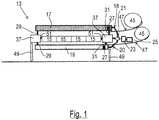
- Packaging machine 13 shown schematically in cross section, comprises a machine frame 37 which is supported on the floor via an underframe 49.
- a left transport chain 51 and a right transport chain 51 are supported by chain guides (not shown) on the respective frame element of the machine frame 37 extending in the transport direction and serve, as described in the introductory part, to transport a lower film through the packaging machine 13, from which, together with an upper film, packs 15 with food products (not shown) received therein.
- the packaging machine 13 has four lanes, ie in each row of packs 41 (cf. Figures 2 to 5 ) are four packs 15 next to each other, which are separated towards the end of the work process.
- the packaging machine 13 is provided with a processing device 11 which is used to process the top and bottom sides of the packs 15.
- the processing device 11 comprises at least one pair of processing units, namely an upper processing unit 17, which is located above the packs 15, and below the packs 15 a lower processing unit 19.
- the processing is the application of labels.
- Both processing units 17, 19, which are each designed as a labeler, are each assigned a structure which, among other things, includes a label supply roll 45 and a feed for the label web 47 rolled up in the supply 45. How out Fig. 1 As can be seen, these structures of the processing units 17, 19 protrude laterally and upwardly beyond the machine frame 37 of the packaging machine 13.
- These structures comprising the supply roll 45 and the label feed (not shown) are each connected to the respective processing unit 17, 19 in such a way that when the respective processing unit 17, 19 is adjusted, they move in the transport direction T of the packaging machine 13 and against the transport direction T - i.e. in the setting direction S (cf. Figures 2 to 5 ) - are always moved together with their respective processing unit 17, 19.
- the adjusting movements of the machining units 17, 19 are guided on the machine frame 37 in the exemplary embodiment shown here.
- guides 29, 31 are provided on the left side and on the right side of the machine frame 37, which are shown in FIG Fig. 1 only schematically and in the Figures 2 to 5 are each indicated as a dash-dotted line.
- the guides 29, 31 can only comprise passive guide elements, such as guide rods for example, which are carried by the machine frame 37 and have no drive function for the respective machining unit 17, 19.
- the provision of a guide for the machining device 11 is not mandatory.
- the adjustment axis 21 can be sufficient to ensure the required stability and guidance and to enable the machining units 17, 19 to be adjusted in the adjustment direction S.
- the illustrated position of the adjustment axis 21 relative to the packaging machine 13 is to be understood purely schematically.
- the adjustment axis 21 can be arranged at any point on one of the machine sides, depending on the specific structure of the packaging machine 13 and in particular of the machine frame 37. In the exemplary embodiments shown here, the adjustment axis 21 is located on the right-hand side of the machine - viewed in the transport direction T.
- the adjustment axis 21 is in the Figures 2 to 5 indicated by a dashed line that is thicker than the guides 29, 31.
- Fig. 1 shows, the upper machining unit 17 and the lower machining unit 19 are each connected to the common adjustment axis 21. This takes place in each case by means of a holder 18, 20, which is only indicated schematically.
- the adjustment axis 21 can be designed, for example, as a threaded spindle extending parallel to the transport direction T, with which spindle nuts formed on the brackets 18, 20 can be coupled.
- the threaded spindle acting as the adjustment axis 21 can be operated manually, for example.
- a preferred embodiment is an in Fig. 1 schematically represented drive 23 is provided, which is connected to a control device 25 and thus enables a controlled adjustment of the machining units 17, 19 by the threaded spindle forming the adjustment axis 21 is set in rotation accordingly.
- the control device 25 can only be assigned to the processing device 11 and connected to a higher-level control device, not shown, of the packaging machine 13. Alternatively, the control device 25 can be integrated into such a central control device.
- a differently configured travel drive can also be provided, which is based, for example, on the drive principle of a toothed belt or a toothed rack.
- each of the two processing units 17, 19 is provided with a coupling device 27, which allows the respective processing unit 17, 19 to be coupled with the adjustment axis 21 or decoupled from the adjustment axis 21 via its holder 18, 20 as required. In this way, an individual, mutually independent adjustment movement of the two processing units 17, 19 is possible.
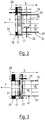
- FIGS. 2 to 5 show examples of different configurations in which the processing units 17, 19 of the processing device 11 on the packaging machine 13 can be positioned and adjusted relative to one another with respect to the transport direction T and in particular with respect to the packaging 15 or packaging rows 41.
- FIG. 2 shows an additional option, which, however, can in principle also be used in all configurations possible according to the invention, namely the provision of an additional unit 35, which is, for example, a printing device can act for printing either the top of the pack or the bottom of the pack.
- a transverse axis 33 extending perpendicular to the transport direction T is provided for this additional unit 35, which - like the processing units 17, 19 - can be moved in the setting direction S by means of the common adjustment axis 21 in order to set the printing position on the top of the pack or on the top of the pack in relation to a pack row 41 To be able to adjust the undersides of the pack.
- the additional unit 35 is also adjustable along the transverse axis 33 in order to be able to reach all packs 15 of a pack row 41. The possible movements of the additional unit 35 thus given are shown in FIG Fig. 2 indicated by the double arrows.
- the upper processing unit 17 and the lower processing unit 19 are assigned to the same row of packs 41 and thus - as seen in the transport direction T - are assigned to the same working section.
- the two processing units 17, 19 are essentially one above the other.
- the offset existing within this same working section between the two processing units 17, 19 in the adjustment direction S can be adjusted by moving the processing units 17, 19 along the adjustment axis 21.
- the processing position with respect to the packs 15 of the relevant pack row 41 can be precisely specified for the upper processing unit 17 as well as for the lower processing unit 19.
- labels can be applied at any desired position on a pack top and a pack bottom, or the top and bottom sides of the packs 15 can be printed at basically any point if the processing units 17, 19 are not labelers, but Printer acts.
- the illustrated longitudinal offset of the machining units 17, 19 in the adjusting direction S can also be zero, ie the machining units 17, 19 can be positioned relative to one another in such a way that they are exactly lie on top of each other.
- the positions of the two processing units 17, 19 in the transport direction T compared to the arrangement in FIG Fig. 2 are interchanged, ie the upper processing unit 17 is further forward in the transport direction T than the lower processing unit 19.
- the two processing units 17, 19 are assigned to different rows of packs 41.
- a longitudinal offset in the adjusting direction S of the two processing units 17, 19 by precisely one row of packs 41 is shown.
- the offset can also be more than one row of packs 41.
- both processing units 17, 19 can only be moved together and are therefore positively coupled. It is also possible, for example, that only the lower machining unit 19 can be moved on the adjustment axis 21, but not the upper machining unit 17, which is for this purpose on a further adjustment axis 21, not shown, which is arranged on the same machine side as the common adjustment axis 21. can be adjusted relative to the lower processing unit 19. Since such a configuration enables joint adjustment by moving the lower machining unit 19 on the adjustment axis 21, the adjustment axis 21 is also a common adjustment axis for the two machining units 17, 19 in this configuration.
- the embodiment of the Fig. 4 is based on the configuration according to Fig. 2 , wherein the processing device 11 here comprises two pairs of processing units 17, 19 and each pair 43 is assigned to a row of packs 41, the two pairs 43 being offset from one another by a row of packs 41 in the transport direction T. It goes without saying that the offset can also be more than one row 41 of packs.
- this can double the processing performance or create the possibility of performing additional processing of the upper sides and / or lower sides of the packs 15, which may also only be done temporarily.
- so-called promotion labels or other additional labels or even printing can be applied to the packs 15 by means of the additional pair 43 of processing units 17, 19.
- FIG. 5 The illustrated embodiment is based on the concept of Fig. 4 .
- Two pairs 43 of processing units 17, 19 are again provided here.
- the above in connection with Fig. 1 The mentioned optional coupling and decoupling of the processing units 17, 19 by means of the coupling devices 27 can for example be used in this configuration for this purpose, for example the in Fig. 5 right pair 43 of processing units 17, 19 from a working position corresponding to the embodiment of FIG Fig. 4 in a non-work position in Fig. 5 to move to the right against the transport direction T, for example to carry out maintenance work or a label supply roll 45 (cf. Fig. 1 ) switch.
- the adjustment of the temporarily interrupted machining units 17, 19 in the state decoupled from the adjustment axis 21 can for example take place manually or by means of a travel drive which has an additional to the common adjustment axis 21 provided adjustment axis (not shown) includes.
- An additional adjustment axis can be assigned to both pairs 43 of machining units 17, 19. Alternatively, each pair 43 can have its own additional adjustment axis.
- an essential advantage of the invention is that the operation of the processing unit can be completely shifted to only one side of the packaging machine. Furthermore, the effort for any necessary safety measures can be reduced, in particular safety measures due to the mobility of the processing units and the associated potential risk of crushing. It is also advantageous that the working length required by the packaging machine for the processing unit according to the invention is comparatively small. In particular, when several pairs of machining units are provided, a saving in the required machine length of 50% and more can be achieved compared to an increase in performance achieved in a conventional manner, without having to accept any losses in functionality or performance.
Landscapes
- Health & Medical Sciences (AREA)
- Public Health (AREA)
- Engineering & Computer Science (AREA)
- Epidemiology (AREA)
- Life Sciences & Earth Sciences (AREA)
- Hydrology & Water Resources (AREA)
- Water Supply & Treatment (AREA)
- Mechanical Engineering (AREA)
- Auxiliary Devices For And Details Of Packaging Control (AREA)
Applications Claiming Priority (1)
| Application Number | Priority Date | Filing Date | Title |
|---|---|---|---|
| DE102018116389.4A DE102018116389A1 (de) | 2018-07-06 | 2018-07-06 | Bearbeitungsvorrichtung für verpackungsmaschinen |
Publications (2)
| Publication Number | Publication Date |
|---|---|
| EP3590853A1 EP3590853A1 (de) | 2020-01-08 |
| EP3590853B1 true EP3590853B1 (de) | 2021-09-15 |
Family
ID=66397092
Family Applications (1)
| Application Number | Title | Priority Date | Filing Date |
|---|---|---|---|
| EP19172470.7A Active EP3590853B1 (de) | 2018-07-06 | 2019-05-03 | Bearbeitungsvorrichtung für verpackungsmaschinen |
Country Status (5)
| Country | Link |
|---|---|
| US (1) | US11319102B2 (da) |
| EP (1) | EP3590853B1 (da) |
| DE (1) | DE102018116389A1 (da) |
| DK (1) | DK3590853T3 (da) |
| ES (1) | ES2893463T3 (da) |
Family Cites Families (9)
| Publication number | Priority date | Publication date | Assignee | Title |
|---|---|---|---|---|
| GB1277725A (en) * | 1969-11-18 | 1972-06-14 | Berkel Patent Nv | A data dispensing device |
| US7383671B2 (en) * | 2004-05-07 | 2008-06-10 | I.M.A. Industria Macchine Automatiche S.P.A. | Blistering machine for producing blister packs |
| ES2476222T3 (es) * | 2005-11-25 | 2014-07-14 | Berhalter Ag, Widnau | Procedimiento para la fabricación de tapas de embalaje o etiquetas sellables parcialmente estampadas y también impresas |
| DE102006047488B4 (de) | 2006-10-05 | 2017-12-21 | Cfs Germany Gmbh | Verpackungsmaschine mit einer Etikettierungsvorrichtung |
| DE102008007890B4 (de) * | 2008-02-07 | 2022-10-13 | Multivac Marking & Inspection Gmbh & Co. Kg | Querbahn-Etikettierverfahren, sowie Etikettierer |
| IT1394099B1 (it) * | 2009-03-24 | 2012-05-25 | Kern Sistemi S R L | Dispositivo per azionare un elemento operatore agente con moto alternativo su un flusso lineare a passo variabile di prodotti |
| EP2974972A1 (de) * | 2014-07-14 | 2016-01-20 | MULTIVAC Marking & Inspection GmbH & Co. KG | Querbahnetikettierer |
| DE102016212130A1 (de) * | 2016-07-04 | 2018-01-04 | Multivac Marking & Inspection Gmbh & Co. Kg | Etikettiermaschine und Verfahren zur Herstellung von Multipacks |
| US11752788B2 (en) * | 2018-03-22 | 2023-09-12 | Hewlett-Packard Development Company, L.P. | Moveable printheads |
-
2018
- 2018-07-06 DE DE102018116389.4A patent/DE102018116389A1/de not_active Withdrawn
-
2019
- 2019-05-03 DK DK19172470.7T patent/DK3590853T3/da active
- 2019-05-03 ES ES19172470T patent/ES2893463T3/es active Active
- 2019-05-03 EP EP19172470.7A patent/EP3590853B1/de active Active
- 2019-06-27 US US16/455,000 patent/US11319102B2/en active Active
Also Published As
| Publication number | Publication date |
|---|---|
| EP3590853A1 (de) | 2020-01-08 |
| ES2893463T3 (es) | 2022-02-09 |
| US11319102B2 (en) | 2022-05-03 |
| US20200010228A1 (en) | 2020-01-09 |
| DE102018116389A1 (de) | 2020-01-09 |
| DK3590853T3 (da) | 2021-10-18 |
Similar Documents
| Publication | Publication Date | Title |
|---|---|---|
| EP3372538B1 (de) | Transportabschnitt, verfahren zum einstellen und/oder verstellen mindestens einer transportbahn innerhalb eines transportabschnitts und verpackungsanlage | |
| EP1990190B1 (de) | Rollendruckmaschine | |
| EP3150521B1 (de) | Vorrichtung zum gruppieren von stückgut und verfahren zum formatwechsel einer solchen vorrichtung | |
| WO2012104251A1 (de) | Vorrichtung und verfahren zum etikettieren von einzelnen packungen von der packungsunterseite her | |
| DE10301178B4 (de) | Vorrichtung zum Ausrichten und Verteilen | |
| EP0665722B1 (de) | Verfahren und anordnung zum fördern flächiger werkstücke | |
| DE3038058A1 (de) | Einrichtung zum aufstapeln von flachen gegenstaenden,insbesondere von faltschachtel-zuschnitten | |
| EP2621430B1 (de) | Verfahren zum verpacken von produkten und verpackungsanlage zur durchführung des verfahrens | |
| EP3187427B2 (de) | Vorrichtung und verfahren zum ergreifen und transportieren von rsc-kartons | |
| EP1975096A1 (de) | Stapelgreifer | |
| EP3375737B1 (de) | Transportabschnitt und verfahren zum einstellen und/oder verstellen mindestens einer transportbahn innerhalb eines transportabschnitts | |
| EP3590853B1 (de) | Bearbeitungsvorrichtung für verpackungsmaschinen | |
| WO2010091771A1 (de) | Schneid- und spreizvorrichtung | |
| DE102013013077A1 (de) | Vorrichtung und Verfahren zum Etikettieren | |
| DE19821603A1 (de) | Längsfalzeinrichtung am Falzapparat von Rotationsdruckmaschinen | |
| DE3886191T2 (de) | Hilfsvorrichtung zum verschliessen der endklappen von tragförmigen kartons. | |
| EP2845663B1 (de) | Biegepresse mit einem Biegewerkzeug aus mehreren Werkzeugelementen | |
| DE69411908T2 (de) | Vorrichtung zum verpacken in faltschachteln | |
| DE102009008936A1 (de) | Schneid- und Spreizvorrichtung | |
| EP1937560B1 (de) | Vorrichtung zum etikettieren von an einer packstoffbahn ausgeformten bechern | |
| DE69919477T2 (de) | Verfahren und Maschine zum Verpacken einer Gruppe von Gegenständen | |
| EP2670673B1 (de) | Vorrichtung und verfahren zum etikettieren von einzelnen packungen von der packungsunterseite her | |
| EP2409922A1 (de) | Führungsvorrichtung einer Spreizeinheit und Verfahren zum Führen von wenigstens einem Materialbahnende in einer Verpackungsmaschine | |
| EP4107004B1 (de) | Druckersystem | |
| EP4414297A1 (de) | Vorrichtung und verfahren zum bewegen von verpackungen |
Legal Events
| Date | Code | Title | Description |
|---|---|---|---|
| PUAI | Public reference made under article 153(3) epc to a published international application that has entered the european phase |
Free format text: ORIGINAL CODE: 0009012 |
|
| STAA | Information on the status of an ep patent application or granted ep patent |
Free format text: STATUS: THE APPLICATION HAS BEEN PUBLISHED |
|
| AK | Designated contracting states |
Kind code of ref document: A1 Designated state(s): AL AT BE BG CH CY CZ DE DK EE ES FI FR GB GR HR HU IE IS IT LI LT LU LV MC MK MT NL NO PL PT RO RS SE SI SK SM TR |
|
| AX | Request for extension of the european patent |
Extension state: BA ME |
|
| STAA | Information on the status of an ep patent application or granted ep patent |
Free format text: STATUS: REQUEST FOR EXAMINATION WAS MADE |
|
| 17P | Request for examination filed |
Effective date: 20200527 |
|
| RBV | Designated contracting states (corrected) |
Designated state(s): AL AT BE BG CH CY CZ DE DK EE ES FI FR GB GR HR HU IE IS IT LI LT LU LV MC MK MT NL NO PL PT RO RS SE SI SK SM TR |
|
| STAA | Information on the status of an ep patent application or granted ep patent |
Free format text: STATUS: EXAMINATION IS IN PROGRESS |
|
| 17Q | First examination report despatched |
Effective date: 20201026 |
|
| GRAP | Despatch of communication of intention to grant a patent |
Free format text: ORIGINAL CODE: EPIDOSNIGR1 |
|
| STAA | Information on the status of an ep patent application or granted ep patent |
Free format text: STATUS: GRANT OF PATENT IS INTENDED |
|
| INTG | Intention to grant announced |
Effective date: 20210412 |
|
| GRAS | Grant fee paid |
Free format text: ORIGINAL CODE: EPIDOSNIGR3 |
|
| GRAA | (expected) grant |
Free format text: ORIGINAL CODE: 0009210 |
|
| STAA | Information on the status of an ep patent application or granted ep patent |
Free format text: STATUS: THE PATENT HAS BEEN GRANTED |
|
| AK | Designated contracting states |
Kind code of ref document: B1 Designated state(s): AL AT BE BG CH CY CZ DE DK EE ES FI FR GB GR HR HU IE IS IT LI LT LU LV MC MK MT NL NO PL PT RO RS SE SI SK SM TR |
|
| REG | Reference to a national code |
Ref country code: CH Ref legal event code: EP |
|
| REG | Reference to a national code |
Ref country code: DE Ref legal event code: R096 Ref document number: 502019002276 Country of ref document: DE |
|
| REG | Reference to a national code |
Ref country code: IE Ref legal event code: FG4D Free format text: LANGUAGE OF EP DOCUMENT: GERMAN |
|
| REG | Reference to a national code |
Ref country code: AT Ref legal event code: REF Ref document number: 1430358 Country of ref document: AT Kind code of ref document: T Effective date: 20211015 |
|
| REG | Reference to a national code |
Ref country code: DK Ref legal event code: T3 Effective date: 20211015 |
|
| REG | Reference to a national code |
Ref country code: NL Ref legal event code: FP |
|
| REG | Reference to a national code |
Ref country code: LT Ref legal event code: MG9D |
|
| PG25 | Lapsed in a contracting state [announced via postgrant information from national office to epo] |
Ref country code: RS Free format text: LAPSE BECAUSE OF FAILURE TO SUBMIT A TRANSLATION OF THE DESCRIPTION OR TO PAY THE FEE WITHIN THE PRESCRIBED TIME-LIMIT Effective date: 20210915 Ref country code: SE Free format text: LAPSE BECAUSE OF FAILURE TO SUBMIT A TRANSLATION OF THE DESCRIPTION OR TO PAY THE FEE WITHIN THE PRESCRIBED TIME-LIMIT Effective date: 20210915 Ref country code: FI Free format text: LAPSE BECAUSE OF FAILURE TO SUBMIT A TRANSLATION OF THE DESCRIPTION OR TO PAY THE FEE WITHIN THE PRESCRIBED TIME-LIMIT Effective date: 20210915 Ref country code: BG Free format text: LAPSE BECAUSE OF FAILURE TO SUBMIT A TRANSLATION OF THE DESCRIPTION OR TO PAY THE FEE WITHIN THE PRESCRIBED TIME-LIMIT Effective date: 20211215 Ref country code: LT Free format text: LAPSE BECAUSE OF FAILURE TO SUBMIT A TRANSLATION OF THE DESCRIPTION OR TO PAY THE FEE WITHIN THE PRESCRIBED TIME-LIMIT Effective date: 20210915 Ref country code: HR Free format text: LAPSE BECAUSE OF FAILURE TO SUBMIT A TRANSLATION OF THE DESCRIPTION OR TO PAY THE FEE WITHIN THE PRESCRIBED TIME-LIMIT Effective date: 20210915 Ref country code: NO Free format text: LAPSE BECAUSE OF FAILURE TO SUBMIT A TRANSLATION OF THE DESCRIPTION OR TO PAY THE FEE WITHIN THE PRESCRIBED TIME-LIMIT Effective date: 20211215 |
|
| REG | Reference to a national code |
Ref country code: ES Ref legal event code: FG2A Ref document number: 2893463 Country of ref document: ES Kind code of ref document: T3 Effective date: 20220209 |
|
| PG25 | Lapsed in a contracting state [announced via postgrant information from national office to epo] |
Ref country code: LV Free format text: LAPSE BECAUSE OF FAILURE TO SUBMIT A TRANSLATION OF THE DESCRIPTION OR TO PAY THE FEE WITHIN THE PRESCRIBED TIME-LIMIT Effective date: 20210915 Ref country code: GR Free format text: LAPSE BECAUSE OF FAILURE TO SUBMIT A TRANSLATION OF THE DESCRIPTION OR TO PAY THE FEE WITHIN THE PRESCRIBED TIME-LIMIT Effective date: 20211216 |
|
| PG25 | Lapsed in a contracting state [announced via postgrant information from national office to epo] |
Ref country code: IS Free format text: LAPSE BECAUSE OF FAILURE TO SUBMIT A TRANSLATION OF THE DESCRIPTION OR TO PAY THE FEE WITHIN THE PRESCRIBED TIME-LIMIT Effective date: 20220115 Ref country code: SM Free format text: LAPSE BECAUSE OF FAILURE TO SUBMIT A TRANSLATION OF THE DESCRIPTION OR TO PAY THE FEE WITHIN THE PRESCRIBED TIME-LIMIT Effective date: 20210915 Ref country code: SK Free format text: LAPSE BECAUSE OF FAILURE TO SUBMIT A TRANSLATION OF THE DESCRIPTION OR TO PAY THE FEE WITHIN THE PRESCRIBED TIME-LIMIT Effective date: 20210915 Ref country code: RO Free format text: LAPSE BECAUSE OF FAILURE TO SUBMIT A TRANSLATION OF THE DESCRIPTION OR TO PAY THE FEE WITHIN THE PRESCRIBED TIME-LIMIT Effective date: 20210915 Ref country code: PT Free format text: LAPSE BECAUSE OF FAILURE TO SUBMIT A TRANSLATION OF THE DESCRIPTION OR TO PAY THE FEE WITHIN THE PRESCRIBED TIME-LIMIT Effective date: 20220117 Ref country code: PL Free format text: LAPSE BECAUSE OF FAILURE TO SUBMIT A TRANSLATION OF THE DESCRIPTION OR TO PAY THE FEE WITHIN THE PRESCRIBED TIME-LIMIT Effective date: 20210915 Ref country code: EE Free format text: LAPSE BECAUSE OF FAILURE TO SUBMIT A TRANSLATION OF THE DESCRIPTION OR TO PAY THE FEE WITHIN THE PRESCRIBED TIME-LIMIT Effective date: 20210915 Ref country code: CZ Free format text: LAPSE BECAUSE OF FAILURE TO SUBMIT A TRANSLATION OF THE DESCRIPTION OR TO PAY THE FEE WITHIN THE PRESCRIBED TIME-LIMIT Effective date: 20210915 Ref country code: AL Free format text: LAPSE BECAUSE OF FAILURE TO SUBMIT A TRANSLATION OF THE DESCRIPTION OR TO PAY THE FEE WITHIN THE PRESCRIBED TIME-LIMIT Effective date: 20210915 |
|
| REG | Reference to a national code |
Ref country code: DE Ref legal event code: R097 Ref document number: 502019002276 Country of ref document: DE |
|
| PLBE | No opposition filed within time limit |
Free format text: ORIGINAL CODE: 0009261 |
|
| STAA | Information on the status of an ep patent application or granted ep patent |
Free format text: STATUS: NO OPPOSITION FILED WITHIN TIME LIMIT |
|
| 26N | No opposition filed |
Effective date: 20220616 |
|
| PG25 | Lapsed in a contracting state [announced via postgrant information from national office to epo] |
Ref country code: SI Free format text: LAPSE BECAUSE OF FAILURE TO SUBMIT A TRANSLATION OF THE DESCRIPTION OR TO PAY THE FEE WITHIN THE PRESCRIBED TIME-LIMIT Effective date: 20210915 |
|
| REG | Reference to a national code |
Ref country code: CH Ref legal event code: PL |
|
| REG | Reference to a national code |
Ref country code: BE Ref legal event code: MM Effective date: 20220531 |
|
| PG25 | Lapsed in a contracting state [announced via postgrant information from national office to epo] |
Ref country code: MC Free format text: LAPSE BECAUSE OF FAILURE TO SUBMIT A TRANSLATION OF THE DESCRIPTION OR TO PAY THE FEE WITHIN THE PRESCRIBED TIME-LIMIT Effective date: 20210915 Ref country code: LU Free format text: LAPSE BECAUSE OF NON-PAYMENT OF DUE FEES Effective date: 20220503 Ref country code: LI Free format text: LAPSE BECAUSE OF NON-PAYMENT OF DUE FEES Effective date: 20220531 Ref country code: IT Free format text: LAPSE BECAUSE OF FAILURE TO SUBMIT A TRANSLATION OF THE DESCRIPTION OR TO PAY THE FEE WITHIN THE PRESCRIBED TIME-LIMIT Effective date: 20210915 Ref country code: CH Free format text: LAPSE BECAUSE OF NON-PAYMENT OF DUE FEES Effective date: 20220531 |
|
| PG25 | Lapsed in a contracting state [announced via postgrant information from national office to epo] |
Ref country code: IE Free format text: LAPSE BECAUSE OF NON-PAYMENT OF DUE FEES Effective date: 20220503 Ref country code: FR Free format text: LAPSE BECAUSE OF NON-PAYMENT OF DUE FEES Effective date: 20220531 |
|
| PG25 | Lapsed in a contracting state [announced via postgrant information from national office to epo] |
Ref country code: BE Free format text: LAPSE BECAUSE OF NON-PAYMENT OF DUE FEES Effective date: 20220531 |
|
| P01 | Opt-out of the competence of the unified patent court (upc) registered |
Effective date: 20230522 |
|
| GBPC | Gb: european patent ceased through non-payment of renewal fee |
Effective date: 20230503 |
|
| REG | Reference to a national code |
Ref country code: NL Ref legal event code: HC Owner name: WEBER FOOD TECHNOLOGY GMBH; DE Free format text: DETAILS ASSIGNMENT: CHANGE OF OWNER(S), CHANGE OF OWNER(S) NAME; FORMER OWNER NAME: WEBER MASCHINENBAU GMBH BREIDENBACH Effective date: 20240206 |
|
| REG | Reference to a national code |
Ref country code: DE Ref legal event code: R081 Ref document number: 502019002276 Country of ref document: DE Owner name: WEBER FOOD TECHNOLOGY SE & CO. KG, DE Free format text: FORMER OWNER: WEBER MASCHINENBAU GMBH BREIDENBACH, 35236 BREIDENBACH, DE Ref country code: DE Ref legal event code: R081 Ref document number: 502019002276 Country of ref document: DE Owner name: WEBER FOOD TECHNOLOGY GMBH, DE Free format text: FORMER OWNER: WEBER MASCHINENBAU GMBH BREIDENBACH, 35236 BREIDENBACH, DE |
|
| PG25 | Lapsed in a contracting state [announced via postgrant information from national office to epo] |
Ref country code: MK Free format text: LAPSE BECAUSE OF FAILURE TO SUBMIT A TRANSLATION OF THE DESCRIPTION OR TO PAY THE FEE WITHIN THE PRESCRIBED TIME-LIMIT Effective date: 20210915 Ref country code: CY Free format text: LAPSE BECAUSE OF FAILURE TO SUBMIT A TRANSLATION OF THE DESCRIPTION OR TO PAY THE FEE WITHIN THE PRESCRIBED TIME-LIMIT Effective date: 20210915 Ref country code: GB Free format text: LAPSE BECAUSE OF NON-PAYMENT OF DUE FEES Effective date: 20230503 |
|
| PG25 | Lapsed in a contracting state [announced via postgrant information from national office to epo] |
Ref country code: HU Free format text: LAPSE BECAUSE OF FAILURE TO SUBMIT A TRANSLATION OF THE DESCRIPTION OR TO PAY THE FEE WITHIN THE PRESCRIBED TIME-LIMIT; INVALID AB INITIO Effective date: 20190503 |
|
| PG25 | Lapsed in a contracting state [announced via postgrant information from national office to epo] |
Ref country code: TR Free format text: LAPSE BECAUSE OF FAILURE TO SUBMIT A TRANSLATION OF THE DESCRIPTION OR TO PAY THE FEE WITHIN THE PRESCRIBED TIME-LIMIT Effective date: 20210915 |
|
| PG25 | Lapsed in a contracting state [announced via postgrant information from national office to epo] |
Ref country code: MT Free format text: LAPSE BECAUSE OF FAILURE TO SUBMIT A TRANSLATION OF THE DESCRIPTION OR TO PAY THE FEE WITHIN THE PRESCRIBED TIME-LIMIT Effective date: 20210915 |
|
| REG | Reference to a national code |
Ref country code: ES Ref legal event code: PC2A Owner name: WEBER FOOD TECHNOLOGY GMBH Effective date: 20241004 |
|
| REG | Reference to a national code |
Ref country code: DE Ref legal event code: R081 Ref document number: 502019002276 Country of ref document: DE Owner name: WEBER FOOD TECHNOLOGY SE & CO. KG, DE Free format text: FORMER OWNER: WEBER FOOD TECHNOLOGY GMBH, 35236 BREIDENBACH, DE |
|
| REG | Reference to a national code |
Ref country code: NL Ref legal event code: PD Owner name: WEBER FOOD TECHNOLOGY SE & CO. KG; DE Free format text: DETAILS ASSIGNMENT: CHANGE OF OWNER(S), CHANGE OF LEGAL ENTITY; FORMER OWNER NAME: WEBER FOOD TECHNOLOGY GMBH Effective date: 20250210 |
|
| PGFP | Annual fee paid to national office [announced via postgrant information from national office to epo] |
Ref country code: NL Payment date: 20250522 Year of fee payment: 7 |
|
| PGFP | Annual fee paid to national office [announced via postgrant information from national office to epo] |
Ref country code: DE Payment date: 20250519 Year of fee payment: 7 |
|
| PGFP | Annual fee paid to national office [announced via postgrant information from national office to epo] |
Ref country code: ES Payment date: 20250616 Year of fee payment: 7 Ref country code: DK Payment date: 20250521 Year of fee payment: 7 |
|
| REG | Reference to a national code |
Ref country code: AT Ref legal event code: MM01 Ref document number: 1430358 Country of ref document: AT Kind code of ref document: T Effective date: 20240503 |
|
| PG25 | Lapsed in a contracting state [announced via postgrant information from national office to epo] |
Ref country code: AT Free format text: LAPSE BECAUSE OF NON-PAYMENT OF DUE FEES Effective date: 20240503 |
|
| REG | Reference to a national code |
Ref country code: ES Ref legal event code: PC2A Owner name: WEBER FOOD TECHNOLOGY SE & CO. KG Effective date: 20251029 |