EP3590775A1 - Gurtaufroller für eine sicherheitsgurteinrichtung eines kraftfahrzeuges - Google Patents
Gurtaufroller für eine sicherheitsgurteinrichtung eines kraftfahrzeuges Download PDFInfo
- Publication number
- EP3590775A1 EP3590775A1 EP19184278.0A EP19184278A EP3590775A1 EP 3590775 A1 EP3590775 A1 EP 3590775A1 EP 19184278 A EP19184278 A EP 19184278A EP 3590775 A1 EP3590775 A1 EP 3590775A1
- Authority
- EP
- European Patent Office
- Prior art keywords
- belt
- friction ring
- clutch
- pawl
- drive wheel
- Prior art date
- Legal status (The legal status is an assumption and is not a legal conclusion. Google has not performed a legal analysis and makes no representation as to the accuracy of the status listed.)
- Granted
Links
Images







Classifications
-
- B—PERFORMING OPERATIONS; TRANSPORTING
- B60—VEHICLES IN GENERAL
- B60R—VEHICLES, VEHICLE FITTINGS, OR VEHICLE PARTS, NOT OTHERWISE PROVIDED FOR
- B60R22/00—Safety belts or body harnesses in vehicles
- B60R22/34—Belt retractors, e.g. reels
- B60R22/36—Belt retractors, e.g. reels self-locking in an emergency
- B60R22/40—Belt retractors, e.g. reels self-locking in an emergency responsive only to vehicle movement
-
- B—PERFORMING OPERATIONS; TRANSPORTING
- B60—VEHICLES IN GENERAL
- B60R—VEHICLES, VEHICLE FITTINGS, OR VEHICLE PARTS, NOT OTHERWISE PROVIDED FOR
- B60R22/00—Safety belts or body harnesses in vehicles
- B60R22/34—Belt retractors, e.g. reels
- B60R22/46—Reels with means to tension the belt in an emergency by forced winding up
- B60R22/4628—Reels with means to tension the belt in an emergency by forced winding up characterised by fluid actuators, e.g. pyrotechnic gas generators
-
- B—PERFORMING OPERATIONS; TRANSPORTING
- B60—VEHICLES IN GENERAL
- B60R—VEHICLES, VEHICLE FITTINGS, OR VEHICLE PARTS, NOT OTHERWISE PROVIDED FOR
- B60R22/00—Safety belts or body harnesses in vehicles
- B60R22/34—Belt retractors, e.g. reels
-
- B—PERFORMING OPERATIONS; TRANSPORTING
- B60—VEHICLES IN GENERAL
- B60R—VEHICLES, VEHICLE FITTINGS, OR VEHICLE PARTS, NOT OTHERWISE PROVIDED FOR
- B60R22/00—Safety belts or body harnesses in vehicles
- B60R22/34—Belt retractors, e.g. reels
- B60R22/46—Reels with means to tension the belt in an emergency by forced winding up
-
- B—PERFORMING OPERATIONS; TRANSPORTING
- B60—VEHICLES IN GENERAL
- B60R—VEHICLES, VEHICLE FITTINGS, OR VEHICLE PARTS, NOT OTHERWISE PROVIDED FOR
- B60R22/00—Safety belts or body harnesses in vehicles
- B60R22/34—Belt retractors, e.g. reels
- B60R22/46—Reels with means to tension the belt in an emergency by forced winding up
- B60R22/4604—Reels with means to tension the belt in an emergency by forced winding up characterised by arrangements in vehicle or relative to seat belt
- B60R2022/4609—Reels with means to tension the belt in an emergency by forced winding up characterised by arrangements in vehicle or relative to seat belt using a plurality of tensioners
-
- B—PERFORMING OPERATIONS; TRANSPORTING
- B60—VEHICLES IN GENERAL
- B60R—VEHICLES, VEHICLE FITTINGS, OR VEHICLE PARTS, NOT OTHERWISE PROVIDED FOR
- B60R22/00—Safety belts or body harnesses in vehicles
- B60R22/34—Belt retractors, e.g. reels
- B60R22/46—Reels with means to tension the belt in an emergency by forced winding up
- B60R2022/4666—Reels with means to tension the belt in an emergency by forced winding up characterised by electric actuators
-
- B—PERFORMING OPERATIONS; TRANSPORTING
- B60—VEHICLES IN GENERAL
- B60R—VEHICLES, VEHICLE FITTINGS, OR VEHICLE PARTS, NOT OTHERWISE PROVIDED FOR
- B60R22/00—Safety belts or body harnesses in vehicles
- B60R22/34—Belt retractors, e.g. reels
- B60R22/46—Reels with means to tension the belt in an emergency by forced winding up
- B60R2022/468—Reels with means to tension the belt in an emergency by forced winding up characterised by clutching means between actuator and belt reel
Definitions
- the present invention relates to a belt retractor for a seat belt device of a motor vehicle with the features of the preamble of claim 1.
- Belt retractors are used in seat belt devices of motor vehicles and are used to wind up one end of a seat belt provided for restraining an occupant.
- the belt retractor is either attached to the vehicle structure or to a vehicle seat attached to the vehicle structure or to a seat bench attached thereto.
- the belt retractor has a frame provided for fastening and a belt reel rotatably mounted in the frame, the seat belt being able to be wound on the belt reel.
- the belt spool is spring-loaded in the winding direction via a drive spring and can be blocked against a further pull-out of the seat belt by means of a blocking device if a predetermined belt pull-out acceleration or vehicle deceleration is exceeded, so that the occupant is subsequently restrained from colliding with the inner vehicle structure to avoid serious injuries ,
- force limiting devices In order to reduce the occupant load during restraint, force limiting devices have been found to be advantageous which, when the belt spool is blocked and a predetermined belt pull-out force is exceeded, allow the belt spool to rotate in the pull-out direction and thus force-limited forward displacement of the occupant. Since the reduction in occupant load that this enables is directly related to the available forward displacement path, it has also proven to be advantageous to pull out the belt loops present in the seat belt before the activation of the force limiting device by means of a belt tensioner in order to enlarge the available forward displacement path, and in order to connect the occupant to the vehicle deceleration as early as possible.
- Reversible belt tensioners have a lower tensioning capacity of approx. 100 to 400 N and are used to pull out the belt loops in a dangerous situation in preparation for a possible subsequent accident. If no accident subsequently occurs, the seat belt is loosened again.
- Electric motors which can be controlled particularly well and reversibly, have proven effective for driving the reversible belt tensioners.
- Irreversible belt tensioners have a higher tensioning capacity of 400 to 1000 N and are only activated when the accident can no longer be avoided, i.e. in an early phase of the accident.
- the irreversible belt tensioners are always activated after the reversible belt tensioners. Pyrotechnic drives have proven themselves as drives for the irreversible belt tensioners, which cannot be activated once they have been activated once, so that in this case the entire seat belt device must be replaced with the irreversible belt tensioner.
- Belt tensioners can attack at different points on the seat belt, e.g. on the belt buckle, the end fitting or also on the belt retractor. When the belt tensioner is used on the belt retractor, this activates the belt spool abruptly in the winding direction when activated, and thereby pulls the belt looseness present in the seat belt out of the seat belt.
- the term belt tensioners should only be understood to mean those which are arranged on a belt retractor and drive the belt reel. Since the belt spool must be able to rotate freely in normal use for buckling up and unbuckling, the drives of both the reversible belt tensioner and the irreversible belt tensioner are only connected to the belt spool when activated via couplings. The couplings should be designed in such a way that they never unintentionally establish a rotary connection, as a result of which the normal use of the belt retractor would be hindered due to a disturbance of the rotary movement of the belt reel caused thereby.
- the coupling of the reversible belt tensioner also be reversible.
- the clutch of the reversible belt tensioner must also be deliberately disengaged if an accident subsequently occurs and the irreversible belt tensioner is activated so that the drive movement of the irreversible belt tensioner is not disturbed by the clutch of the reversible belt tensioner which is still engaged.
- the couplings of the various belt tensioners must be designed such that they automatically establish the rotary connection between the drive and the belt reel when the drive is activated, which e.g. can be caused by friction, by inertial forces or by a control contour.
- the movement of the clutch is thereby positively controlled by the beginning movement of the drive.
- the couplings are required to perform the coupling movement automatically when the drive device is activated, but under other circumstances, to deliberately not to carry out the coupling movement in order to avoid an unwanted coupling connection.
- a belt retractor with a reversible belt tensioner from the applicant is known, which has a friction-controlled clutch with two clutch pawls and a friction ring.
- the friction ring has two control arms, and is coupled to the clutch pawls by the clutch pawls in a first embodiment engaging with control pins in each of an elongated hole of a control arm, or by the clutch pawls in a second embodiment having funnel-shaped recesses into which the control pins engage.
- the clutch pawls are each guided in a longitudinally displaceable manner in elongate recesses of a drive wheel which can be driven by an electric motor.
- the friction ring itself is clipped into the drive wheel and rests on a fixed dome of a pretensioner cover via friction feet. Furthermore, the belt spool projects with an annular internally toothed extension into an annular recess that surrounds the coupling pawls of the drive wheel radially on the outside.
- the invention is therefore based on the object of providing a belt retractor of the generic type in which the likelihood of undesired engagement of the tensioner clutch is reduced or the control of the engagement and disengagement movement of the tensioner clutch is improved.
- the friction ring and / or the clutch pawl have a blocking contour which is positioned in such a way that the clutch pawl comes into contact with it after the disengaged movement from the toothing and in the direction of a repeated engaged movement in the teeth are blocked.
- the advantage of the solution according to the invention can be seen in the fact that the coupling pawl due to the blocking contour in a parking position against unwanted interference in the toothing due to e.g. strong vibration is blocked.
- the clutch pawl is not only controlled in motion via the control arm of the friction ring, but also, in a defined position after and before activation, a form-fitting system on the blocking contour is blocked. Since this effect is achieved solely by shaping the friction ring and / or the clutch pawl, the function can be realized without additional parts and almost cost-neutral in the production of the two parts.
- the blocking contour is deliberately arranged in such a way that the coupling pawl is only blocked in a defined position, which is referred to here as the parking position, and that it can otherwise carry out the entry and exit movement undisturbed.
- the park position of the clutch pawl is defined by the arrangement of the blocking contour and the relative movement of the clutch pawl relative to the friction ring or vice versa, the relative movement in turn from that between the friction ring and the drive wheel or from that between the friction ring and a fixed counter surface of the housing or a frictional force acting on this part depends. Furthermore, the movement of the clutch pawl to the drive wheel and vice versa can also be used.
- the coupling realized via the control arm between the friction ring and the clutch pawl has play, and that the playful coupling, when the belt tensioner is activated, enables a relative movement of the friction ring and / or the coupling pawl to unblock the clutch pawl.
- the advantage of the proposed further development can be seen in the fact that the release of the blocking of the clutch pawl requires a slight relative movement of the friction ring and / or the clutch pawl, so the belt tensioner must be activated consciously in order to release the blockage of the clutch pawl.
- the activation of the belt tensioner is not blocked, in that the blocking is released in a first step by the relative movement, and only then is the coupling pawl then pushed into the engagement position in the toothing for coupling the drive wheel with the belt spool.
- the friction ring and / or the clutch pawl can have a control contour which urges the clutch pawl into the blocked position during the relative movement to the friction ring.
- the movement of the clutch pawl is thus controlled, and the blocked position or parking position of the clutch pawl can thereby e.g. also be laterally offset to the displacement path of the clutch pawl.
- the control contour can be formed, for example, by a ramp. Starting from the linear displacement path, the ramp forces the coupling pawl to perform a continuous pivoting or offset movement, the movement of the coupling pawl in particular not being able to catch on the control contour by means of steps or edges.
- the controlled movement of the clutch pawl into the blocked position is therefore a continuous movement. If the ramp is provided on the friction ring, it is oriented such that it rises into the blocked position against the direction of movement of the friction ring during the relative movement of the clutch pawl. If the ramp is arranged on the clutch pawl, on the other hand, it is oriented such that it rises against the direction of movement of the clutch pawl during the relative movement into the locked position of the clutch pawl.
- the blocking contour can be formed in the form of a finger protruding from the friction ring, on which the coupling pawl comes to rest in the blocked position.
- the protruding finger practically forms a positive stop for the coupling pawl, by means of which the movement of the coupling pawl is blocked in a process-reliable manner.
- the finger is preferably positioned on the friction ring in such a way that the coupling pawl comes into contact with the toothing on the finger in the direction of the engagement direction. This can e.g. be realized by a front face of the coupling pawl on the finger.
- the blocking contour can alternatively or additionally be provided on the coupling pawl, in which case the drive wheel preferably has a counter contour on which the clutch pawl is in the locked position with the locking contour. If the locking contour is only provided on the clutch pawl, the friction ring does not have to be changed, the locking of the clutch pawl is only realized via the clutch pawl itself, the clutch pawl practically hooks itself with the locking contour on the opposite contour of the drive wheel, whereby the hooking or blocking additionally can be triggered or enforced by a control contour provided on the coupling pawl or on the friction ring and interacting with a counter surface. If a blocking contour is provided both on the clutch pawl and on the friction ring, the blocking can be further improved and, in particular, redundancy can be created if the blocking should not work via one of the blocking contours.
- the friction ring be formed from a metal sheet by a multiply formed stamped part.
- the friction ring can also be formed by a plastic injection-molded part, the blocking contour being able to be shaped at the same time as the friction ring is being sprayed, at no additional cost.
- the coupling pawl can preferably be formed by a metal sintered part, so that even a very complex shape with e.g. a blocking contour or different control contours can be produced without additional post-processing and in particular without machining post-processing.
- the belt retractor as such is not shown, but of course has the usual components and corresponds in its basic structure to that in the documents DE 100 59 227 C1 and EP 1 663 737 B1 described seat belt retractors.
- the belt retractor has a belt spool which is rotatably mounted in a frame which can be fastened to the vehicle and which serves to wind up a seat belt of the seat belt device.
- a drive device for example in the form of an electric motor, is held on the frame and can be brought into drive connection with the belt reel by means of the tensioner coupling described below.
- the belt retractor can additionally have a force limiting device, an irreversible belt tensioner and various additional functions.
- the belt reel not shown, has a non-rotatably connected or also integrally molded, hood-shaped extension 16 with a radially inner toothing 20, which, for example, in the Figure 2 can be seen.
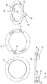
- the tensioner clutch comprises as basic components an externally toothed drive wheel 1, two clutch pawls 2 and 3, a friction ring 4 and one in the Figure 2 Pretensioner cover to be recognized 17.
- the drive device drives the externally toothed drive wheel 1 when activated via a gear to tighten the seat belt in winding direction A and can be added to the illustration (see Figure 3 ).
- the externally toothed drive wheel 1 has a central opening 25, an annular recess 18 and two channel-shaped recesses 15 and 19 provided within the annular recess 18, each with two at least sectionally linear guide surfaces.
- two coupling pawls 2 and 3 are linearly displaceable, each of which has teeth 6 and 7 on their radially outer sides in the installed position for engagement in the toothing 20 of the extension 16 of the belt spool.
- the coupling pawls 2 and 3 each have a funnel-shaped recess 8, 9 on the side surfaces facing the belt reel or the extension 16, with two opposite side walls 10 running towards one another in the installed position towards the radial outside.
- the friction ring 4 has two opposing control arms 11 arranged at an angle of 180 degrees to one another and two blocking contours 12 likewise arranged opposite one another at an angle of 180 degrees in the form of fingers protruding radially outwards. Furthermore, the friction ring 4 on the radial inner side has a plurality of spaced axially directed friction feet 21 arranged on one diameter.
- the tensioner clutch is mounted by first placing a tensioner cover 17 from the rear onto the drive wheel 1 and thereby with an annular extension 24 into the central opening 25 of the drive wheel 1 and with the in the Figure 13 fixing pin 29 to be recognized is inserted into an opening 30 in each case. Then the clutch pawls 2 and 3 placed in the recesses 15 and 19, and the friction ring 4 placed so that it rests with the friction feet 21 on the inside of the annular extension 24.
- the friction ring 4 is mounted in the assembled initial position so that the clutch pawls 2 and 3 are arranged in a retracted position and do not engage the teeth 20 with the teeth 6 and 7, as shown in FIG Figure 2 can be seen.
- the coupling pawls 2 and 3 also rest with their end faces on the fingers of the friction ring 4, so that they are blocked against an unintentional extension movement.
- the tensioner clutch is now open and the belt reel of the belt retractor can rotate freely.
- the control arms 11 are located at the entrance of the funnel-shaped recesses 8 and 9, radially below the side walls 10 of the funnel-shaped recesses 8 and 9 arranged on the rear side of the coupling pawls 2 and 3.
- the movement of the clutch pawls 2 and 3 is thus practically limited on two sides, namely on the front side by the blocking contour 12 and on the back by the side wall 10, and the clutch pawls 2 and 3 are prevented from accidentally engaging with the toothing 20 .
- the solution according to the invention can in particular prevent the coupling pawls 2 and 3 from engaging with the toothing 20 during subsequent activation of an irreversible belt tensioner and thereby the irreversible tightening movement of the seat belt to disturb.
- the clutch pawl 3 is in a parking position, in which it is in an inserted position and does not engage with the teeth 20 with its teeth 7.
- This position in the top left of the Figure 3 corresponds to that in the Figure 2 position shown, and it is going to the to the Figure 2 related description referenced.
- the drive wheel 1 is driven in the direction of arrow A.
- the friction ring 4 is deliberately coupled with a play in the recess 8 with the clutch pawl 3 via the control arm 11.
- the friction ring 4 performs a relative movement in the recess 8 to the drive wheel 1 in the direction of arrow C during the initial phase of the drive movement of the drive wheel 1, during which it does not move the clutch pawl 3 until it faces the teeth 7 laterally with the control arm 11 front side wall 10 of the recess 8 comes to rest.
- the blocking contour 12 in the form of the protruding finger is moved away from the end face of the clutch pawl 3, so that the clutch pawl 3 is unblocked.
- the game of the friction ring 4 to the clutch pawl 3 is deliberately designed so that the friction ring 4 can be moved from the blocking parking position with the clutch pawl 3 at a standstill until the blocking of the clutch pawl 3 is deliberately released before the friction ring 4 starts the extension movement of the Coupling pawl 3 starts to be controlled via the control arm 11. Subsequently, the friction ring 4 pushes the clutch pawl 3 radially outwards out of the recess 15 via the control arm 11 until it engages with the teeth 7 in the toothing 20 and thereby drives the belt spool over the extension 16 in the winding direction, as in the top right illustration the Figure 3 can be seen.
- the tensioning of the seat belt is released again in the event that no accident occurs, and the seat belt is deliberately loosened again by the drive device of the belt tensioner, i.e. the electric motor, driving the drive wheel 1 by a small rotation angle in the opposite direction of rotation drives in the direction of arrow B.
- the drive wheel 1 performs a relative movement to the friction ring 4 due to the rotational movement in the direction of arrow B, or in other words, the friction ring 4 performs a relative rotational movement in the direction of the arrow D until it contacts the control arm 11 laterally on the rear side wall 10 of the recess 8 arrives, as in the lower left illustration of the Figure 3 can be seen.
- the clutch pawl 3 is pulled out of the toothing 20 via the control arm 11 until it is in the lower, middle representation of the Figure 3 is located, and the belt reel with the extension 16 can rotate freely with respect to the clutch pawl 3.
- the control arm 11 comes to rest under the rear side surface 10 of the recess 8, and the blocking contour 12 in the form of the finger comes into a position in which it locks on the end face of the clutch pawl 3 System arrives and subsequently pushes it into the final parking position during the further relative movement.
- the coupling pawl 3 is subsequently blocked in the parking position at the front end by the finger of the friction ring 4 against unwanted extension and at the rear end by the end face of the control arm 11, which lies under the rear side surface 10 of the recess 8, against an unwanted deflection to the extent that it cannot unintentionally engage the teeth 20 with the teeth 7.
- the clutch pawls 2 and 3 have in the embodiment of the Figures 5 and 6 each have a blocking contour 12 in the form of a radially outwardly projecting cam 34 and a hook 32 provided at the rear end.
- the drive wheel 1 has a counter contour 23 which extends through a recess with a shape corresponding to the cams 34 on the radially outer guide surfaces of the recesses 15 and 19 and through two recesses corresponding to the hook 32, which extend into the recesses 15 and 19 Projections is formed.
- the friction ring 4 has in addition to the control arms 11 instead of the blocking contour 12 in the embodiment of FIG Figures 1 to 4 a control contour 22 in the form of ramps arranged at a distance from the control arms 11 and rising against the relative rotational movement of the friction ring 4.
- the clutch pawls 2 and 3 each have a contour surface 26 on their inner sides facing the friction ring 4, on which the friction ring 4 with the ramps comes into contact with the parking position during the retraction movement.
- the clutch pawls 2 and 3 are continuously raised and fixed with the blocking contour 12 formed by the cams 34 and the hooks 32 on the respective counter-contour 23 of the drive wheel 1 and blocked in the park position.
- the friction ring 4 leads in the same way as in the embodiment of FIG Figures 1 to 4 a slight relative rotational movement to the fixed clutch pawls 2 and 3 in the opposite direction of rotation, during which the clutch pawls 2 and 3 with the blocking contour 12 disengage from the respective counter contour 23.
- the control arms 11 are inclined here in the direction of the teeth 6 and 7 of the clutch pawls 2 and 3, ie in the extension direction of the clutch pawls 2 and 3.
- the front side surfaces 10 of the recesses 8 and 9 are also inclined in such a way that they correspond to the inner side of the clutch pawls 2 and 3 include an angle of less than 90 degrees.
- the clutch pawls 2 and 3 are guided during the extension movement via the control arms 11 via a forward and radially slightly inwardly directed thrust force, which counteracts the tendency of the clutch pawls 2 and 3 to lift off radially and counteracts the guidance of the clutch pawls 2 and 3 as such can be improved.
- the clutch pawls 2 and 3 each have a contour surface 26 on the rear side surfaces 10 of the recesses 8 and 9, on which the friction ring 4 comes into contact with the control contours 22 provided on the control arms 11, as a result of which the clutch pawls 2 and 3 are raised at their ends and are lifted over the counter contour 23 formed by the projections until they engage behind the projections with the hooks 32 blocking.
- FIG. 9 to 15 Another embodiment of the invention can be seen, in which, in addition to the control arms 11 on the friction ring 4, likewise similar to the embodiment of FIG Figures 5 and 6 two additional control contours 22 are provided.
- the control contours 22 are realized here in the form of radially protruding projections with two slopes or ramps that rise to form a roof shape.
- the control arms 11 are similar to the embodiment of FIG Figures 5 and 6 inclined in the direction of the extension movement of the clutch pawls 2 and 3.
- the front side surfaces 10 of the recesses 8 and 9 in the extension direction of the clutch pawls 2 and 3 are inclined, specifically in the direction of the teeth 6 and 7, so that they form an angle of less than 90 degrees with the radially inner guide surfaces of the clutch pawls 2 and Include 3.
- the clutch pawls 2 and 3 each have a contour surface 26 on their undersides, on which the friction ring 4 comes into contact with the control contour 22, as a result of which the clutch pawls 2 and 3 during the inward and outward movement have the shape of the control contours 22 and the contour surface 26 perform the predetermined sequence of movements.
- a blocking contour 12 in the form of a hook 34 provided at the rear end and in the form of a recess 33 provided on the upper side is provided on the coupling pawls 2 and 3.
- an elongated nose 31 aligned in the direction of displacement of the clutch pawls 2 and 3 is provided on the undersides of the clutch pawls 2 and 3.
- the pretensioner cover 17 can be seen as a single part, which has two axially protruding fixing pins 29, with which the pretensioner cover 17 can be fixed in openings 30 of the pretensioner drive wheel 1 which correspond to the shape and are arranged identically.
- two protruding guide blocks 27 with a triangular cross section are also provided, which in the mounted position of the pretensioner cover 17 engage in corresponding free spaces which adjoin the recesses 15 and 19 of the drive wheel 1 and thereby at least a portion of the guide surfaces for the clutch pawls Form 2 and 3.
- the guide blocks 27 are on the side, which form the guide surfaces for the clutch pawls 2 and 3, each with a guide groove 28 into which the clutch pawls 2 and 3 in the corresponding movement phase shortly before and during the engagement in the toothing 20 with the lugs 31 engage so that the clutch pawls 2 and 3 are additionally guided vertically, laterally to the direction of movement and cannot be deflected laterally. This additionally ensures that the clutch pawls 2 and 3 do not inadvertently disengage the toothing 20.
- the drive wheel 1 has on the guide surfaces of the recesses 15 and 19 each have a counter contour 23 in the form of a radially outer step and a protrusion protruding into the recesses 15 and 19.
- the coupling pawls 2 and 3 come into contact with the control contour 22 of the friction ring 4 in a position of the withdrawal movement with the contour surface 26 and are thereby fixed with the blocking contour 12 on the counter contour 23 of the drive wheel 1, so that they subsequently prevent an unintentional extension movement or an unintentional intervention in the toothing 20 are blocked.
- the drive wheel 1 can be seen with the clutch pawl 3 blocked in the park position.
- the coupling pawl 3 rests with the contour surface 26 on the outer surface of the control contour 22 and is supported on the rear side surface 10 of the recess 8 by the top of the control arm 11.
- the clutch pawl 3 exerts a slightly eccentric force F on the friction ring 4 via the contour surface 26, as a result of which a torque M acting clockwise in the illustration is exerted on it.
- This torque M pushes the friction ring 4 with the control contour 22 in the direction of the recess 8 of the clutch pawl 3, and the clamping force exerted on the counter contour 23 via the blocking contour 12 is simultaneously increased.
- the coupling pawl 3 thereby clamps itself practically even when vibrations occur and cannot shake itself out of the park position.
Landscapes
- Engineering & Computer Science (AREA)
- Mechanical Engineering (AREA)
- Automotive Seat Belt Assembly (AREA)
Abstract
Description
- Die vorliegende Erfindung betrifft einen Gurtaufroller für eine Sicherheitsgurteinrichtung eines Kraftfahrzeuges mit den Merkmalen des Oberbegriffs von Anspruch 1.
- Gurtaufroller werden in Sicherheitsgurteinrichtungen von Kraftfahrzeugen verwendet und dienen dazu, ein Ende eines zur Rückhaltung eines Insassen vorgesehenen Sicherheitsgurtes aufzuwickeln. Der Gurtaufroller ist entweder an der Fahrzeugstruktur oder an einem an der Fahrzeugstruktur befestigten Fahrzeugsitz bzw. an einer daran befestigten Sitzbank befestigt. Der Gurtaufroller weist in seinem Grundaufbau einen zur Befestigung vorgesehenen Rahmen und eine in dem Rahmen drehbar gelagerte Gurtspule auf, wobei der Sicherheitsgurt auf der Gurtspule aufwickelbar ist. Die Gurtspule ist über eine Triebfeder in Aufwickelrichtung federbelastet und über eine Blockiereinrichtung bei einem Überschreiten einer vorbestimmten Gurtbandauszugsbeschleunigung oder Fahrzeugverzögerung mittels einer Blockiereinrichtung gegen einen weiteren Auszug des Sicherheitsgurtes blockierbar, so dass der Insasse nachfolgend zur Vermeidung schwererer Verletzungen vor einem Aufprall auf die innere Fahrzeugstruktur zurückgehalten wird.
- Um die Insassenbelastung bei der Rückhaltung zu reduzieren, haben sich Kraftbegrenzungseinrichtungen als vorteilhaft herausgestellt, welche bei blockierter Gurtspule und Überschreiten einer vorbestimmten Gurtbandauszugskraft eine kraftbegrenzte Drehung der Gurtspule in Auszugsrichtung und damit eine kraftbegrenzte Vorwärtsverlagerung des Insassen ermöglichen. Da die dadurch ermöglichte Reduzierung der Insassenbelastung unmittelbar mit dem zur Verfügung stehenden Vorverlagerungsweg zusammenhängt, hat es sich ferner als vorteilhaft herausgestellt, die in dem Sicherheitsgurt vorhandene Gurtlose vor der Aktivierung der Kraftbegrenzungseinrichtung durch einen Gurtstraffer herauszuziehen, um den zur Verfügung stehenden Vorverlagerungsweg zu vergrößern, und um den Insassen möglichst frühzeitig an die Fahrzeugverzögerung anzukoppeln.
- Bei Gurtstraffern wird zwischen reversiblen Gurtstraffern und irreversiblen Gurtstraffern oder auch Leistungsstraffern unterschieden. Reversible Gurtstraffer haben eine geringere Straffleistung von ca. 100 bis 400 N und dienen dazu, die Gurtlose in einer Gefahrensituation zur Vorbereitung auf einen möglichen nachfolgenden Unfall herauszuziehen. Tritt nachfolgend kein Unfall ein, so wird der Sicherheitsgurt wieder gelockert. Zum Antrieb der reversiblen Gurtstraffer haben sich Elektromotoren bewährt, welche besonders gut und reversibel zu steuern sind. Irreversible Gurtstraffer weisen eine höhere Straffleistung von 400 bis 1000 N auf und werden erst dann aktiviert, wenn der Unfall nicht mehr zu vermeiden ist, also in einer Frühphase des Unfalles. Die irreversiblen Gurtstraffer werden also zeitlich immer nach den reversiblen Gurtstraffern aktiviert. Als Antriebe für die irreversiblen Gurtstraffer haben sich pyrotechnische Antriebe bewährt, welche nach ihrer einmaligen Aktivierung nicht mehr aktiviert werden können, so dass in diesem Fall die gesamte Sicherheitsgurteinrichtung mit dem irreversiblen Gurtstraffer ausgetauscht werden muss.
- Gurtstraffer können dabei an unterschiedlichen Stellen des Sicherheitsgurtes angreifen, so z.B. an dem Gurtschloss, dem Endbeschlag oder auch an dem Gurtaufroller. Bei der Anwendung des Gurtstraffers am Gurtaufroller treibt dieser die Gurtspule bei einer Aktivierung schlagartig in Aufwickelrichtung an und zieht dadurch die in dem Sicherheitsgurt vorhandene Gurtlose aus dem Sicherheitsgurt. Im Sinne der vorliegenden Erfindung sollen unter dem Begriff Gurtstraffer nur solche verstanden werden, welche an einem Gurtaufroller angeordnet sind und die Gurtspule antreiben. Da die Gurtspule sich grundsätzlich im Normalgebrauch zum Anschnallen und zum Abschnallen frei drehen können muss, werden die Antriebe sowohl des reversiblen Gurtstraffers als auch des irreversiblen Gurtstraffers erst bei einer Aktivierung über Kupplungen mit der Gurtspule verbunden. Die Kupplungen sollten dabei so beschaffen sein, dass sie in keinem Fall unbeabsichtigt eine Drehverbindung herstellen, wodurch der Normalgebrauch des Gurtaufrollers aufgrund einer dadurch verursachten Störung der Drehbewegung der Gurtspule behindert werden würde.
- Da der reversible Gurtstraffer für den Fall, dass nachfolgend kein Unfall eintritt, wieder deaktiviert und der Gurtaufroller wieder normal verwendet werden soll, muss die Kupplung des reversiblen Gurtstraffers überdies ebenfalls reversibel ausgebildet sein. Ferner muss die Kupplung des reversiblen Gurtstraffers auch dann bewusst außer Eingriff gebracht werden, wenn nachfolgend ein Unfall auftritt und der irreversible Gurtstraffer aktiviert wird, damit die Antriebsbewegung des irreversiblen Gurtstraffers nicht durch die noch im Eingriff befindliche Kupplung des reversiblen Gurtstraffers gestört wird.
- Ferner müssen die Kupplungen der verschiedenen Gurtstraffer so ausgebildet sein, dass sie die Drehverbindung zwischen dem Antrieb und der Gurtspule bei einer Aktivierung des Antriebes selbsttätig herstellen, was z.B. durch Reibung, durch Trägheitskräfte oder auch durch eine Steuerkontur bewirkt werden kann. Die Bewegung der Kupplung wird dadurch durch die beginnende Bewegung des Antriebes zwangsgesteuert.
- Damit wird an die Kupplungen einerseits die Anforderung gestellt, dass sie die Kupplungsbewegung bei einer Aktivierung der Antriebseinrichtung selbsttätig ausführen sollen, unter anderen Umständen die Kupplungsbewegung aber bewusst nicht ausführen sollen, um eine ungewollte Kupplungsverbindung zu vermeiden.
- Aus der Druckschrift
EP 1 663 737 B1 ist zum Beispiel ein Gurtaufroller mit einem reversiblen Gurtstraffer der Anmelderin bekannt, welcher eine reibungsgesteuerte Kupplung mit zwei Kupplungsklinken und einem Reibring aufweist. Der Reibring weist zwei Steuerarme auf, und ist mit den Kupplungsklinken dadurch gekoppelt, indem die Kupplungsklinken in einem ersten Ausführungsbeispiel mit Steuerstiften in jeweils ein Langloch eines Steuerarmes eingreifen, oder indem die Kupplungsklinken in einem zweiten Ausführungsbeispiel trichterförmige Ausnehmungen aufweisen, in welche die Steuerstifte eingreifen. Die Kupplungsklinken sind jeweils in länglichen Ausnehmungen eines von einem Elektromotor antreibbaren Antriebsrad längsverschieblich geführt. Der Reibring selbst ist in das Antriebrad eingeclipst und liegt über Reibfüße an einem feststehenden Dom einer Strafferabdeckung an. Ferner ragt die Gurtspule mit einem ringförmigen innenverzahnten Fortsatz in eine ringförmige, die Kupplungsklinken des Antriebsrades radial außen umfassende Ausnehmung hinein. - Das Prinzip der Auslösung der Kupplungsbewegung der Kupplung ist in dem deutschen Patent
DE 100 59 227 C1 der Anmelderin beschrieben und ist auch in der Kupplung derEP 1 663 737 B1 verwirklicht, so dass diesbezüglich auf diese Druckschriften verwiesen wird. - In dem in der
EP 1 663 737 B1 beschriebenen Ausführungsbeispiel wird zunächst das Antriebsrad über den Elektromotor und ein Getriebe in Drehung versetzt. Dabei wird der Reibring aufgrund der über die Reibfüße aufgebrachten Reibkräfte bewusst gegenüber dem Antriebsrad zurückgehalten, wodurch die in den Ausnehmungen des Antriebrades verschieblich gelagerten Kupplungsklinken zu einer Ausfahrbewegung gezwungen werden und zum Eingriff in die Innenverzahnung des Fortsatzes der Gurtspule gelangen. - Es hat sich herausgestellt, dass die Kupplungsklinken trotz der Kopplung mit dem Reibring über die Steuerarme unter extremen Erschütterungen, wie z.B. bei einer nachfolgenden Aktivierung eines irreversiblen Gurtstraffers unbeabsichtigt in Eingriff mit der Innenverzahnung des Fortsatzes der Gurtspule gelangen können.
- Der Erfindung liegt daher die Aufgabe zu Grunde, einen Gurtaufroller der gattungsgemäßen Art bereitzustellen, bei der die Wahrscheinlichkeit eines ungewollten Einkuppelns der Strafferkupplung reduziert bzw. die Steuerung der Ein- und Auskupplungsbewegung der Strafferkupplung verbessert ist.
- Zur Lösung der Aufgabe wird ein Gurtaufroller mit den Merkmalen von Anspruch 1 vorgeschlagen. Weitere bevorzugte Ausführungsformen der Erfindung sind den Unteransprüchen, den Figuren und der zugehörigen Beschreibung zu entnehmen.
- Gemäß dem Grundgedanken der Erfindung wird vorgeschlagen, dass der Reibring und/oder die Kupplungsklinke eine Blockierkontur aufweist, welche derart positioniert ist, und dass die Kupplungsklinke nach der außer Eingriff Bewegung aus der Verzahnung daran zur Anlage gelangt und in Richtung einer wiederholten in Eingriff Bewegung in die Verzahnung blockiert ist.
- Der Vorteil der erfindungsgemäßen Lösung ist darin zu sehen, dass die Kupplungsklinke durch die Blockierkontur in einer Parkstellung gegen einen ungewollten Eingriff in die Verzahnung aufgrund z.B. starker Erschütterungen blockiert ist. Die Kupplungsklinke wird dadurch nicht nur in der Bewegung über den Steuerarm des Reibringes gesteuert, sondern überdies in einer definierten Stellung nach und vor der Aktivierung noch eine formschlüssige Anlage an der Blockierkontur blockiert. Da dieser Effekt allein durch eine Formgestaltung des Reibringes und/oder der Kupplungsklinke erreicht wird, kann die Funktion ohne zusätzliche Teile und nahezu kostenneutral bei der Herstellung der beiden Teile verwirklicht werden. Die Blockierkontur wird dabei bewusst so angeordnet, dass die Kupplungsklinke ausschließlich in einer definierten Stellung, welche hier als Parkstellung bezeichnet wird, blockiert ist, und dass sie ansonsten die Ein- und Ausfahrbewegung ungestört ausführen kann. Dabei wird die Parkstellung der Kupplungsklinke durch die Anordnung der Blockierkontur und die ausgeführte Relativbewegung der Kupplungsklinke zu dem Reibring bzw. umgekehrt definiert, wobei die Relativbewegung wiederum von den zwischen dem Reibring und dem Antriebsrad bzw. von den zwischen dem Reibring und einer feststehenden Gegenfläche des Gehäuses oder eines an diesem gehaltenen Teiles wirkenden Reibkräften abhängt. Ferner kann dabei auch die Bewegung der Kupplungsklinke zu dem Antriebsrad und umgekehrt genutzt werden. Das heißt die Kupplungsklinke gelangt erst durch den Bewegungsablauf der genannten Teile in die blockierte Stellung, wobei bei dem Bewegungsablauf, die Relativbewegung des Reibringes, der Kupplungsklinke und des Antriebsrades in beliebiger Kombination zum Blockieren der Kupplungsklinken in der Parkstellung bzw. zum Erreichen der Parkstellung genutzt werden kann.
- Weiter wird vorgeschlagen, dass die über den Steuerarm zwischen dem Reibring und der Kupplungsklinke verwirklichte Kopplung spielbehaftet ist, und die spielbehaftete Kopplung bei einer Aktivierung des Gurtstraffers eine die Kupplungsklinke deblockierende Relativbewegung des Reibringes und/oder der Kupplungsklinke ermöglicht. Der Vorteil der vorgeschlagenen Weiterentwicklung ist darin zu sehen, dass die Freigabe der Blockierung der Kupplungsklinke eine geringe Relativbewegung des Reibringes und/oder der Kupplungsklinke voraussetzt, der Gurtstraffer muss also bewusst aktiviert werden, um die Blockierung der Kupplungsklinke zu lösen. Ferner wird die Aktivierung des Gurtstraffers dadurch nicht blockiert, indem die Blockierung in einem ersten Schritt durch die Relativbewegung zuerst gelöst wird, und die Kupplungsklinke erst dann anschließend in die Eingriffsstellung in die Verzahnung zur Kupplung des Antriebsrades mit der Gurtspule geschoben wird.
- Weiter können der Reibring und/oder die Kupplungsklinke eine Steuerkontur aufweisen, welche die Kupplungsklinke während der Relativbewegung zu dem Reibring in die blockierte Stellung drängt. Die Bewegung der Kupplungsklinke erfolgt damit gesteuert, und die blockierte Stellung bzw. Parkstellung der Kupplungsklinke kann dadurch z.B. auch seitlich versetzt zu dem Verschiebeweg der Kupplungsklinke angeordnet sein.
- Dabei kann die Steuerkontur zum Beispiel durch eine Rampe gebildet sein. Die Rampe zwingt der Kupplungsklinke ausgehend von dem linearen Verschiebeweg eine kontinuierliche Schwenk- oder Versatzbewegung auf, wobei die Bewegung der Kupplungsklinke insbesondere nicht durch Stufen oder Kanten an der Steuerkontur haken kann. Die gesteuerte Bewegung der Kupplungsklinke in die blockierte Stellung ist damit eine kontinuierliche Bewegung. Sofern die Rampe an dem Reibring vorgesehen ist, ist sie so ausgerichtet, dass sie entgegen der Bewegungsrichtung des Reibringes während der Relativbewegung der Kupplungsklinke in die blockierte Stellung ansteigt. Sofern die Rampe an der Kupplungsklinke angeordnet ist, ist sie hingegen so ausgerichtet, dass sie entgegen der Bewegungsrichtung der Kupplungsklinke während der Relativbewegung in die blockierte Stellung der Kupplungsklinke ansteigt.
- Ferner kann die Blockierkontur in Form eines von dem Reibring vorstehenden Fingers gebildet sein, an dem die Kupplungsklinke in der blockierten Stellung zur Anlage gelangt. Der vorstehende Finger bildet praktisch einen formschlüssigen Anschlag für die Kupplungsklinke, durch welchen die Bewegung der Kupplungsklinke prozesssicher blockiert wird. Der Finger ist dabei bevorzugt so an dem Reibring positioniert, dass die Kupplungsklinke daran in Richtung der Eingriffsrichtung in die Verzahnung an dem Finger zur Anlage gelangt. Dies kann z.B. durch eine stirnseitige Anlage der Kupplungsklinke an dem Finger verwirklicht sein.
- Ferner kann die Blockierkontur alternativ oder zusätzlich an der Kupplungsklinke vorgesehen sein, wobei das Antriebsrad in diesem Fall bevorzugt eine Gegenkontur aufweist, an welcher die Kupplungsklinke in der blockierten Stellung mit der Blockierkontur anliegt. Sofern die Blockierkontur nur an der Kupplungsklinke vorgesehen ist, muss der Reibring nicht verändert werden, das Blockieren der Kupplungsklinke wird ausschließlich über die Kupplungsklinke selbst verwirklicht, die Kupplungsklinke verhakt sich praktisch selbst mit der Blockierkontur an der Gegenkontur des Antriebsrades, wobei das Verhaken oder Blockieren zusätzlich durch eine an der Kupplungsklinke oder an dem Reibring vorgesehene mit einer Gegenfläche zusammenwirkende Steuerkontur ausgelöst bzw. erzwungen werden kann. Sofern sowohl an der Kupplungsklinke als auch an dem Reibring eine Blockierkontur vorgesehen ist, kann das Blockieren weiter verbessert und insbesondere eine Redundanz geschaffen werden, sofern das Blockieren über eine der Blockierkonturen nicht wirken sollte.
- Weiter wird vorgeschlagen, dass der Reibring durch ein mehrfach umgeformtes Stanzteil aus einem Metallblech gebildet ist. Der Vorteil dieser Lösung ist darin zu sehen, dass die Blockierkontur beim Stanzen und Umformen des Reibringes mit sehr geringen, nur durch die zusätzlichen Umformschritte bedingten Mehrkosten hergestellt werden kann.
- Ferner kann der Reibring auch durch ein Kunststoffspritzteil gebildet sein, wobei die Blockierkontur gleich bei dem Spritzen des Reibringes ohne Mehrkosten mitgeformt werden kann.
- Ferner kann die Kupplungsklinke bevorzugt durch ein Metallsinterteil gebildet sein, so dass auch eine sehr komplexe Formgebung mit z.B. einer Blockierkontur oder verschiedenen Steuerkonturen ohne eine zusätzliche Nachbearbeitung und insbesondere ohne eine spanende Nachbearbeitung hergestellt werden kann.
- Die Erfindung wird im Folgenden anhand verschiedener bevorzugter Ausführungsformen unter Bezugnahme auf die beigefügten Figuren erläutert. Dabei zeigt
- Fig. 1
- ein Antriebsrad mit einem Reibring und Kupplungsklinken als Einzelteile; und
- Fig. 2
- ein Ausschnitt des Antriebsrades mit einer blockierten Kupplungsklinke; und
- Fig. 3
- den Ausschnitt des Antriebsrades mit der Kupplungsklinke in verschiedenen Stellungen während der Ein- und Ausfahrbewegung; und
- Fig. 4
- das Antriebsrad mit der in einer blockierten Stellung angeordneten Kupplungsklinke in verschiedenen Stellungen unter Einwirkung von äußeren Kräften; und
- Fig. 5 und 6
- ein Antriebsrad mit einem Reibring und zwei Kupplungsklinken nach einem zweiten Ausführungsbeispiel; und
- Fig. 7 und 8
- ein Antriebsrad mit einem Reibring und zwei Kupplungsklinken nach einem dritten Ausführungsbeispiel; und
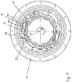
- Fig. 9 bis 15
- ein Antriebsrad mit einem Reibring und zwei Kupplungsklinken nach einem vierten Ausführungsbeispiel.
- In den Figuren sind nur die Einzelteile der Strafferkupplung dargestellt. Der Gurtaufroller als solches ist nicht dargestellt, weist aber selbstverständlich die üblichen Bauteile auf und entspricht in dem Grundaufbau den in den Druckschriften
DE 100 59 227 C1 undEP 1 663 737 B1 beschriebenen Sicherheitsgurtaufrollern. - Der Gurtaufroller weist in seinem Grundaufbau eine Gurtspule auf, welche drehbar in einem fahrzeugfest befestigbaren Rahmen gelagert ist und der Aufwicklung eines Sicherheitsgurtes der Sicherheitsgurteinrichtung dient. An dem Rahmen ist eine Antriebseinrichtung z.B. in Form eines Elektromotors gehalten, welche über die nachfolgend noch beschriebene Strafferkupplung mit der Gurtspule in Antriebsverbindung gebracht werden kann. Ferner kann der Gurtaufroller zusätzlich eine Kraftbegrenzungseinrichtung, einen irreversiblen Gurtstraffer und diverse Zusatzfunktionen aufweisen.
- Die nicht dargestellte Gurtspule weist einen drehfest verbundenen oder auch einstückig angeformten, haubenförmigen Fortsatz 16 mit einer radial inneren Verzahnung 20 auf, welcher z.B. in der
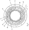
Figur 2 zu erkennen ist. - Die Strafferkupplung umfasst als Grundbestandteile ein außenverzahntes Antriebsrad 1, zwei Kupplungsklinken 2 und 3, einen Reibring 4 und eine in der
Figur 2 zu erkennende Strafferabdeckung 17. Die Antriebseinrichtung treibt das außenverzahnte Antriebsrad 1 bei einer Aktivierung über ein Getriebe zur Straffung des Sicherheitsgurtes in Aufwickelrichtung A an und kann in der Darstellung hinzugedacht werden (sieheFigur 3 ). - Das außenverzahnte Antriebsrad 1 weist eine zentrische Öffnung 25, eine ringförmige Ausnehmung 18 und zwei innerhalb der ringförmigen Ausnehmung 18 vorgesehene, kanalförmige Ausnehmungen 15 und 19 mit jeweils zwei wenigstens abschnittsweise linearen Führungsflächen auf. In den kanalförmigen Ausnehmungen 15 und 19 sind zwei Kupplungsklinken 2 und 3 linear verschieblich geführt, welche jeweils an ihren in der Einbaustellung radial außen liegenden Seiten Zähne 6 und 7 zum Eingriff in die Verzahnung 20 des Fortsatzes 16 der Gurtspule aufweisen. Ferner weisen die Kupplungsklinken 2 und 3 an den der Gurtspule bzw. dem Fortsatz 16 zugewandten Seitenflächen jeweils eine trichterförmige Ausnehmung 8, 9 mit zwei gegenüberliegenden, in der Einbaustellung zu der Radialaußenseite hin aufeinander zu laufenden Seitenwänden 10 auf.
- Der Reibring 4 weist zwei gegenüberliegend, in einem Winkel von 180 Grad zueinander angeordnete Steuerarme 11 und zwei ebenfalls gegenüberliegend in einem Winkel von 180 Grad zueinander angeordnete Blockierkonturen 12 in Form von radial nach außen vorstehenden Fingern auf. Ferner weist der Reibring 4 an der Radialinnenseite eine Mehrzahl von beabstandeten, auf einem Durchmesser angeordneten, axial gerichteten Reibfüßen 21 auf.
- Die Strafferkupplung wird montiert, indem zuerst eine Strafferabdeckung 17 von der Rückseite auf das Antriebsrad 1 aufgesetzt und dabei mit einem ringförmigen Fortsatz 24 in die zentrische Öffnung 25 des Antriebsrades 1 und mit den in der
Figur 13 zu erkennenden Fixierzapfen 29 in jeweils eine Öffnung 30 eingeführt wird. Anschließend werden die Kupplungsklinken 2 und 3 in die Ausnehmungen 15 und 19 eingelegt, und der Reibring 4 so aufgesetzt, dass er mit den Reibfüßen 21 an der Innenseite des ringförmigen Fortsatzes 24 anliegt. - Der Reibring 4 ist in der montierten Anfangsstellung so montiert, dass die Kupplungsklinken 2 und 3 in einer eingefahrenen Stellung angeordnet sind und mit den Zähnen 6 und 7 nicht in die Verzahnung 20 eingreifen, wie dies in der
Figur 2 zu erkennen ist. Die Kupplungsklinken 2 und 3 liegen ferner mit ihren Stirnflächen an den Fingern des Reibringes 4 an, so dass sie gegen eine unbeabsichtigte Ausfahrbewegung blockiert sind. Die Strafferkupplung ist damit offen und die Gurtspule des Gurtaufrollers kann sich frei drehen. Die Steuerarme 11 befinden sich am Eintritt der trichterförmigen Ausnehmungen 8 und 9, radial unter den an der Rückseite der Kupplungsklinken 2 und 3 angeordneten Seitenwänden 10 der trichterförmigen Ausnehmungen 8 und 9. - In dieser blockierten Stellung der Kupplungsklinken 2 und 3 können diese durch die stirnseitige Anlage an der durch die Finger des Reibringes 4 gebildeten Blockierkontur 12 und durch die Begrenzung der Auslenkung der Kupplungsklinken 2 und 3 durch die an den Seitenwänden 10 zur Anlage gelangenden Steuerarme 11 des Reibringes 4, weder durch eine Längsverschiebung in der Darstellung nach links noch durch ungerichtete Erschütterungen mit den Zähnen 7 und 6 in die Verzahnung 20 des Fortsatzes 16 in Eingriff gelangen, wie in der rechten Darstellung der
Figur 4 zu erkennen ist. Die Bewegung der Kupplungsklinken 2 und 3 wird damit praktisch an zwei Seiten nämlich an der Stirnseite durch die Blockierkontur 12 und an der Rückseite durch die Seitenwand 10 begrenzt, und es wird verhindert, dass die Kupplungsklinken 2 und 3 ungewollt in Eingriff mit der Verzahnung 20 gelangen. Sofern die Strafferkupplung zur Verbindung eines reversiblen Gurtstraffers mit der Gurtspule verwendet wird, kann durch die erfindungsgemäße Lösung insbesondere verhindert werden, dass die Kupplungsklinken 2 und 3 bei einer nachfolgenden Aktivierung eines irreversiblen Gurtstraffers in Eingriff mit der Verzahnung 20 gelangen und dadurch die irreversible Straffbewegung des Sicherheitsgurtes stören. - In der
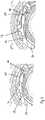
Figur 3 ist in den oberen Darstellungen ausgehend von links nach rechts die Strafferkupplung in verschiedenen Stellungen des Reibringes 4 und der Kupplungsklinke 3 in einer Anfangsphase der Aktivierung des Gurtstrafferantriebes bis zu dem vollständigen Eingriff der Kupplungsklinke 3 in die Verzahnung 20 zu erkennen. In den unteren Darstellungen von links nach rechts ist dieselbe Kupplungsklinke 3 in verschiedenen Stellungen aus der Eingriffsstellung bis hin zu einer Parkstellung in einer Endphase der Aktivierung des Gurtstrafferantriebes zu erkennen. - Zu Beginn der Aktivierung des Gurtstraffers befindet sich die Kupplungsklinke 3 in einer Parkstellung, in welcher sie sich in einer eingeschobenen Stellung befindet und mit ihren Zähnen 7 nicht in die Verzahnung 20 eingreift. Diese Stellung in der linken oberen Darstellung der
Figur 3 entspricht der in derFigur 2 gezeigten Stellung, und es wird auf die zu derFigur 2 zugehörige Beschreibung verwiesen. - Wird der Gurtstraffer aktiviert, so wird das Antriebsrad 1 in Pfeilrichtung A angetrieben. Der Reibring 4 ist über den Steuerarm 11 bewusst mit einem Spiel in der Ausnehmung 8 mit der Kupplungsklinke 3 gekoppelt. Dadurch führt der Reibring 4 während der Anfangsphase der Antriebsbewegung des Antriebsrades 1 eine Relativbewegung in der Ausnehmung 8 zu dem Antriebsrad 1 in Pfeilrichtung C aus, während der er die Kupplungsklinke 3 nicht bewegt, bis er seitlich mit dem Steuerarm 11 an der den Zähnen 7 zugewandten vorderen Seitenwand 10 der Ausnehmung 8 zur Anlage gelangt. Gleichzeitig wird dadurch die Blockierkontur 12 in Form des vorstehenden Fingers von der Stirnfläche der Kupplungsklinke 3 weg bewegt, so dass die Kupplungsklinke 3 deblockiert wird. Das Spiel des Reibringes 4 zu der Kupplungsklinke 3 ist dabei bewusst so ausgelegt, dass der Reibring 4 ausgehend von der blockierenden Parkstellung bei stillstehender Kupplungsklinke 3 soweit bewegt werden kann, bis die Blockierung der Kupplungsklinke 3 bewusst aufgehoben ist, bevor der Reibring 4 die Ausfahrbewegung der Kupplungsklinke 3 beginnt über den Steuerarm 11 zu steuern. Nachfolgend schiebt der Reibring 4 die Kupplungsklinke 3 über den Steuerarm 11 radial nach außen aus der Ausnehmung 15 aus, bis sie mit den Zähnen 7 in die Verzahnung 20 eingreift und dadurch die Gurtspule über den Fortsatz 16 in Aufwickelrichtung antreibt, wie in der rechten oberen Darstellung der
Figur 3 zu erkennen ist. - Nach erfolgter Straffbewegung wird die Straffung des Sicherheitsgurtes in dem Fall, wenn kein Unfall auftritt, wieder aufgehoben, und der Sicherheitsgurt wird bewusst wieder gelockert, indem die Antriebseinrichtung des Gurtstraffers also der Elektromotor das Antriebsrad 1 zu einer Drehbewegung um einen kleinen Drehwinkel in die entgegengesetzte Drehrichtung in Pfeilrichtung B antreibt. Diese Bewegung ist in den unteren Darstellungen zu erkennen. Das Antriebsrad 1 führt aufgrund der Drehbewegung in Pfeilrichtung B eine Relativbewegung zu dem Reibring 4 aus, oder anders ausgedrückt, der Reibring 4 führt eine Relativdrehbewegung in Pfeilrichtung D aus, bis er mit dem Steuerarm 11 seitlich an der hinteren Seitenwand 10 der Ausnehmung 8 zur Anlage gelangt, wie in der linken unteren Darstellung der
Figur 3 zu erkennen ist. Nachfolgend wird die Kupplungsklinke 3 über den Steuerarm 11 aus der Verzahnung 20 herausgezogen, bis sie sich in der unteren, mittleren Darstellung derFigur 3 befindet, und die Gurtspule mit dem Fortsatz 16 frei gegenüber der Kupplungsklinke 3 drehen kann. Während der weiteren Relativdrehbewegung des Reibringes 4 zu dem Antriebsrad 1 gelangt der Steuerarm 11 zur Anlage unter die hintere Seitenfläche 10 der Ausnehmung 8, und die Blockierkontur 12 in Form des Fingers gelangt in eine Stellung, in welcher sie an der Stirnfläche der Kupplungsklinke 3 blockierend zur Anlage gelangt und diese nachfolgend während der weiteren Relativbewegung in die finale Parkposition schiebt. Die Kupplungsklinke 3 ist nachfolgend in der Parkposition an dem vorderen Ende durch den Finger des Reibringes 4 gegen ein ungewolltes Ausfahren und an dem hinteren Ende durch die unter der hinteren Seitenfläche 10 der Ausnehmung 8 anliegende Stirnseite des Steuerarmes 11 gegen eine ungewollte Auslenkung soweit blockiert, dass sie mit den Zähnen 7 nicht ungewollt in die Verzahnung 20 in Eingriff gelangen kann. - Die Beschreibung des Kupplungs- und Entkupplungsvorganges wurde in den
Figuren 2 bis 4 allein anhand der Kupplungsklinke 3 vorgenommen, sie gilt aber selbstverständlich auch identisch für die gegenüberliegende, zweite Kupplungsklinke 2. Ferner wurde die Beschreibung des Bewegungsablaufes für ein einfacheres Verständnis anhand eines in einer unveränderten Stellung stehenden Antriebsrades 1 vorgenommen, und der Reibring 4 wurde stattdessen relativ gegenüber dem Antriebsrad 1 verdreht. In der Wirklichkeit wird selbstverständlich auch das Antriebsrad 1 gedreht, und der Reibring 4 wird durch die reibschlüssige, stirnseitige Anlage an dem Fortsatz 16 und an der Strafferabdeckung 17 zu der Relativbewegung gegenüber den Antriebsrad 1 gezwungen. Bei der Annahme eines stillstehenden Antriebsrades 1 entspricht diese Relativbewegung aber der dargestellten Relativbewegung des Reibringes 4 in die Pfeilrichtungen C und D. - In den
Figuren 5 bis 15 sind weitere Ausführungsbeispiele der weiterentwickelten Strafferkupplung gezeigt, wobei diese Ausführungsbeispiele nur bezüglich der sich von dem Ausführungsbeispiel derFig. 1 bis 4 unterscheidenden Merkmale beschrieben werden. - Die Kupplungsklinken 2 und 3 weisen in dem Ausführungsbeispiel der
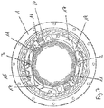
Figuren 5 und6 jeweils eine Blockierkontur 12 in Form eines radial nach außen vorstehenden Nockens 34 und eines an dem rückwärtigen Ende vorgesehen Hakens 32 auf. Das Antriebsrad 1 weist eine Gegenkontur 23 auf, welche durch jeweils eine Ausnehmung mit einer zu den Nocken 34 formkorrespondierenden Formgebung an den radial äußeren Führungsflächen der Ausnehmungen 15 und 19 und durch zwei zu den Haken 32 formkorrespondierenden, sich in die Ausnehmungen 15 und 19 hinein erstreckenden Vorsprünge gebildet ist. Ferner weist der Reibring 4 neben den Steuerarmen 11 statt der Blockierkontur 12 in dem Ausführungsbeispiel derFiguren 1 bis 4 eine Steuerkontur 22 in Form von in einem Abstand zu den Steuerarmen 11 angeordneten, entgegen der Relativdrehbewegung des Reibringes 4 ansteigenden Rampen auf. Die Kupplungsklinken 2 und 3 weisen an ihren dem Reibring 4 zugewandten Innenseiten jeweils eine Konturfläche 26 auf, an welcher der Reibring 4 mit den Rampen während der Rückzugsbewegung in die Parkposition zur Anlage gelangt. Dadurch werden die Kupplungsklinken 2 und 3 kontinuierlich angehoben und mit der durch die Nocken 34 und die Haken 32 gebildeten Blockierkontur 12 an der jeweiligen Gegenkontur 23 des Antriebsrades 1 festgelegt und in der Parkposition blockiert. Zum Lösen der Blockierung der Kupplungsklinken 2 und 3 führt der Reibring 4 in gleicher Weise wie in dem Ausführungsbeispiel derFiguren 1 bis 4 eine geringe Relativdrehbewegung zu den feststehenden Kupplungsklinken 2 und 3 in die entgegengesetzte Drehrichtung aus, während der sich die Kupplungsklinken 2 und 3 mit der Blockierkontur 12 von der jeweiligen Gegenkontur 23 lösen. Die Steuerarme 11 sind hier in Richtung der Zähne 6 und 7 der Kupplungsklinken 2 und 3 also in Ausfahrrichtung der Kupplungsklinken 2 und 3 geneigt. Die vorderen Seitenflächen 10 der Ausnehmungen 8 und 9 sind ebenfalls geneigt und zwar so, dass sie mit der inneren Seite der Kupplungsklinken 2 und 3 einen Winkel von weniger als 90 Grad einschließen. Dadurch werden die Kupplungsklinken 2 und 3 während der Ausfahrbewegung über die Steuerarme 11 über jeweils eine vorwärts und radial leicht einwärts gerichtete Schubkraft geführt, wodurch der Tendenz des radial nach außen Abhebens der Kupplungsklinken 2 und 3 entgegengewirkt und die Führung der Kupplungsklinken 2 und 3 als solches verbessert werden kann. - In den
Figuren 7 und8 ist ein gegenüber dem Ausführungsbeispiel derFiguren 5 und6 weiter vereinfachtes Ausführungsbeispiel zu erkennen, bei dem die Steuerkontur 22 an dem Reibring 4 in Form von an die Steuerarme 11 angeformten Rampen gebildet ist. Die Blockierkontur 12 ist hier allein durch die an den rückwärtigen Enden der Kupplungsklinken 2 und 3 vorgesehenen Haken 32 gebildet, welche die Kupplungsklinken 2 und 3 identisch zu dem Ausführungsbeispiel derFiguren 5 und6 in der Parkposition blockieren. Die Kupplungsklinken 2 und 3 weisen jeweils eine Konturfläche 26 an den hinteren Seitenflächen 10 der Ausnehmungen 8 und 9 auf, an denen der Reibring 4 mit den an den Steuerarmen 11 vorgesehenen Steuerkonturen 22 zur Anlage gelangt, wodurch die Kupplungsklinken 2 und 3 an ihren Enden angehoben und über die durch die Vorsprünge gebildete Gegenkontur 23 gehoben werden, bis sie die Vorsprünge mit den Haken 32 blockierend hintergreifen. - In den
Figuren 9 bis 15 ist ein weiteres Ausführungsbeispiel der Erfindung zu erkennen, bei dem an dem Reibring 4 neben den Steuerarmen 11 ebenfalls ähnlich zu dem Ausführungsbeispiel derFiguren 5 und6 zwei zusätzliche Steuerkonturen 22 vorgesehen sind. Die Steuerkonturen 22 sind hier in Form von radial vorstehenden Vorsprüngen mit zwei zueinander zu einer Dachform ansteigenden Schrägen bzw. Rampen verwirklicht. Die Steuerarme 11 sind ähnlich wie in dem Ausführungsbeispiel derFiguren 5 und6 in Richtung der Ausfahrbewegung der Kupplungsklinken 2 und 3 geneigt. In gleicher Weise sind die in Ausfahrrichtung der Kupplungsklinken 2 und 3 vorderen Seitenflächen 10 der Ausnehmungen 8 und 9 geneigt und zwar in Richtung der Zähne 6 und 7, so dass sie einen Winkel von kleiner als 90 Grad mit den radial inneren Führungsflächen der Kupplungsklinken 2 und 3 einschließen. Ferner weisen die Kupplungsklinken 2 und 3 an ihren Unterseiten jeweils eine Konturfläche 26 auf, an denen der Reibring 4 mit der Steuerkontur 22 zur Anlage gelangt, wodurch die Kupplungsklinken 2 und 3 während der Ein- und Ausfahrbewegung einen durch die Form der Steuerkonturen 22 und der Konturfläche 26 vorgegebenen Bewegungsablauf ausführen. An den Kupplungsklinken 2 und 3 ist jeweils eine Blockierkontur 12 in Form eines an dem hinteren Ende vorgesehenen Hakens 34 und in Form einer an der Oberseite vorgesehenen Vertiefung 33 vorgesehen. Außerdem ist an den Unterseiten der Kupplungsklinken 2 und 3 jeweils eine längliche, in Verschiebungsrichtung der Kupplungsklinken 2 und 3 ausgerichtete Nase 31 vorgesehen. - In der
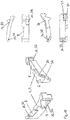
Figur 13 ist die Strafferabdeckung 17 als Einzelteil zu erkennen, welche zwei axial abragende Fixierzapfen 29 aufweist, mit denen die Strafferabdeckung 17 in formentsprechenden und identisch angeordneten Öffnungen 30 des Strafferantriebsrades 1 festlegbar ist. An der Strafferabdeckung 17 sind außerdem zwei im Querschnitt dreieckförmige, vorstehende Führungsblöcke 27 vorgesehen, welche in der montierten Stellung der Strafferabdeckung 17 in entsprechende Freiräume eingreifen, welche an die Ausnehmungen 15 und 19 des Antriebsrades 1 angrenzen und dadurch zumindest einen Abschnitt der Führungsflächen für die Kupplungsklinken 2 und 3 bilden. Die Führungsblöcke 27 sind an der Seite, welche die Führungsflächen für die Kupplungsklinken 2 und 3 bilden jeweils mit einer Führungsnut 28 versehen, in welche die Kupplungsklinken 2 und 3 in der entsprechenden Bewegungsphase kurz vor und während des Eingriffs in die Verzahnung 20 mit den Nasen 31 eingreifen, so dass die Kupplungsklinken 2 und 3 zusätzlich senkrecht, seitlich zu der Bewegungsrichtung geführt werden und nicht seitlich ausgelenkt werden können. Damit ist zusätzlich sichergestellt, dass die Kupplungsklinken 2 und 3 nicht ungewollt außer Eingriff der Verzahnung 20 gelangen. - Das Antriebsrad 1 weist an den Führungsflächen der Ausnehmungen 15 und 19 jeweils eine Gegenkontur 23 in Form einer radial außen vorgesehenen Stufe und einem in die Ausnehmungen 15 und 19 vorstehenden Vorsprung auf. Die Kupplungsklinken 2 und 3 gelangen in einer Stellung der Rückzugsbewegung mit der Konturfläche 26 zur Anlage an der Steuerkontur 22 des Reibringes 4 und werden dadurch mit der Blockierkontur 12 an der Gegenkontur 23 des Antriebsrades 1 festgelegt, so dass sie nachfolgend gegen eine unbeabsichtigte Ausfahrbewegung bzw. einen unbeabsichtigten Eingriff in die Verzahnung 20 blockiert sind.
- In der
Figur 15 ist das Antriebsrad 1 mit der in der Parkstellung blockierten Kupplungsklinke 3 zu erkennen. Die Kupplungsklinke 3 liegt mit der Konturfläche 26 an der äußeren Fläche der Steuerkontur 22 an und wird an der hinteren Seitenfläche 10 der Ausnehmung 8 durch die Oberseite des Steuerarmes 11 unterstützt. Für den Fall, dass Erschütterungen auf die Kupplungsklinke 3 einwirken, übt die Kupplungsklinke 3 über die Konturfläche 26 eine geringfügig exzentrische Kraft F auf den Reibring 4 aus, wodurch auf diesen ein in der Darstellung im Uhrzeigersinn wirkendes Drehmoment M ausgeübt wird. Durch dieses Drehmoment M wird der Reibring 4 mit der Steuerkontur 22 in Richtung der Ausnehmung 8 der Kupplungsklinke 3 gedrängt, und die über die Blockierkontur 12 auf die Gegenkontur 23 ausgeübte Klemmkraft wird gleichzeitig erhöht. Die Kupplungsklinke 3 klemmt sich dadurch bei auftretenden Erschütterungen praktisch selbst fest und kann sich nicht selbsttätig aus der Parkstellung losrütteln.
Claims (9)
- Gurtaufroller für eine Sicherheitsgurteinrichtung eines Kraftfahrzeuges mit- einer drehbar gelagerten Gurtspule, auf welcher ein Sicherheitsgurt der Sicherheitsgurteinrichtung aufwickelbar ist, und- einem Gurtstraffer mit einem Antriebsrad (1), welcher bei einer Aktivierung die Gurtspule in Aufwickelrichtung antreibt, und- einer die Antriebsbewegung von dem Antriebsrad (1) auf die Gurtspule übertragenden zwangsgesteuerten Strafferkupplung, mit- wenigstens einer an dem Antriebsrad (1) verschiebbar gelagerten Kupplungsklinke (2,3), welche zur Schaffung und Aufhebung einer Drehverbindung des Antriebsrades (1) mit der Gurtspule in Eingriff und außer Eingriff einer in Bezug zu der Gurtspule drehfesten Verzahnung (20) bewegbar ist, und- einem Reibring (4), welcher einen Steuerarm (11) aufweist, der mit der Kupplungsklinke (2,3) gekoppelt ist, wobei- der Reibring (4) bei einer Aktivierung des Gurtstraffers eine durch Reibkräfte erzwungene Relativbewegung zu dem Antriebsrad (1) ausführt und durch die Relativbewegung die Bewegung der Kupplungsklinke (2,3) in Eingriff und außer Eingriff der Verzahnung (20) über den Steuerarm (11) steuert,dadurch gekennzeichnet, dass- der Reibring (4) und/oder die Kupplungsklinke (2,3) eine Blockierkontur (12) aufweist, welche derart positioniert ist, dass die Kupplungsklinke (2,3) nach der außer Eingriff Bewegung aus der Verzahnung (20) daran zur Anlage gelangt und in Richtung einer wiederholten in Eingriff Bewegung in die Verzahnung (20) blockiert ist.
- Gurtaufroller nach Anspruch 1, dadurch gekennzeichnet, dass- die über den Steuerarm (11) zwischen dem Reibring (4) und der Kupplungsklinke (2,3) verwirklichte Kopplung spielbehaftet ist, und- die spielbehaftete Kopplung bei einer Aktivierung des Gurtstraffers eine die Kupplungsklinke (2,3) deblockierende Relativbewegung des Reibringes (4) und/oder der Kupplungsklinke (2,3) ermöglicht.
- Gurtaufroller nach einem der Ansprüche 1 oder 2, dadurch gekennzeichnet, dass- der Reibring (4) und/oder die Kupplungsklinke (2,3) eine Steuerkontur (22) aufweisen, welche die Kupplungsklinke (2,3) während der Relativbewegung zu dem Reibring (4) in eine blockierte Stellung drängt.
- Gurtaufroller nach Anspruch 3, dadurch gekennzeichnet, dass- die Steuerkontur (22) durch eine Rampe gebildet ist.
- Gurtaufroller nach einem der vorangegangenen Ansprüche, dadurch gekennzeichnet, dass- die Blockierkontur (12) in Form eines von dem Reibring (4) vorstehenden Fingers gebildet ist, an dem die Kupplungsklinke (2,3) in der blockierten Stellung zur Anlage gelangt.
- Gurtaufroller nach einem der vorangegangenen Ansprüche, dadurch gekennzeichnet, dass- die Blockierkontur (12) an der Kupplungsklinke (2,3) vorgesehen ist, und- das Antriebsrad (1) eine Gegenkontur (23) aufweist, an welcher die Kupplungsklinke (2,3) in der blockierten Stellung mit der Blockierkontur (12) anliegt.
- Gurtaufroller nach einem der vorangegangenen Ansprüche, dadurch gekennzeichnet, dass- der Reibring (4) durch ein mehrfach umgeformtes Stanzteil aus einem Metallblech gebildet ist.
- Gurtaufroller nach einem der Ansprüche 1 bis 6, dadurch gekennzeichnet, dass- der Reibring (4) durch ein Kunststoffspritzteil gebildet ist.
- Gurtaufroller nach einem der vorangegangenen Ansprüche, dadurch gekennzeichnet, dass- die Kupplungsklinke (2,3) ein Metallsinterteil ist.
Applications Claiming Priority (1)
| Application Number | Priority Date | Filing Date | Title |
|---|---|---|---|
| DE102018211226.6A DE102018211226B4 (de) | 2018-07-06 | 2018-07-06 | Gurtaufroller für eine Sicherheitsgurteinrichtung eines Kraftfahrzeuges |
Publications (2)
| Publication Number | Publication Date |
|---|---|
| EP3590775A1 true EP3590775A1 (de) | 2020-01-08 |
| EP3590775B1 EP3590775B1 (de) | 2022-01-26 |
Family
ID=67180575
Family Applications (1)
| Application Number | Title | Priority Date | Filing Date |
|---|---|---|---|
| EP19184278.0A Active EP3590775B1 (de) | 2018-07-06 | 2019-07-03 | Gurtaufroller für eine sicherheitsgurteinrichtung eines kraftfahrzeuges |
Country Status (6)
| Country | Link |
|---|---|
| US (1) | US11235732B2 (de) |
| EP (1) | EP3590775B1 (de) |
| JP (1) | JP6751186B2 (de) |
| KR (1) | KR102209224B1 (de) |
| CN (1) | CN110682889B (de) |
| DE (1) | DE102018211226B4 (de) |
Families Citing this family (4)
| Publication number | Priority date | Publication date | Assignee | Title |
|---|---|---|---|---|
| DE102019203356B4 (de) * | 2019-03-12 | 2021-05-12 | Autoliv Development Ab | Reversibler Gurtstraffer für einen Sicherheitsgurt |
| DE102022123954A1 (de) * | 2022-09-19 | 2024-03-21 | Autoliv Development Ab | Gurtaufroller für eine Sicherheitsgurteinrichtung eines Kraftfahrzeuges |
| DE102022123958A1 (de) * | 2022-09-19 | 2024-03-21 | Autoliv Development Ab | Gurtaufroller für eine Sicherheitsgurteinrichtung eines Kraftfahrzeuges |
| DE102022123957A1 (de) * | 2022-09-19 | 2024-03-21 | Autoliv Development Ab | Gurtaufroller für eine Sicherheitsgurteinrichtung eines Kraftfahrzeuges |
Citations (4)
| Publication number | Priority date | Publication date | Assignee | Title |
|---|---|---|---|---|
| DE10059227C1 (de) | 2000-11-29 | 2002-03-14 | Autoliv Dev | Gurtstraffer mit weich ansteuerbarer Strafferkupplung |
| WO2005021339A1 (de) * | 2003-08-26 | 2005-03-10 | Autoliv Development Ab | Gurtaufroller mit zwei straffvorrichtungen |
| EP1663737A1 (de) | 2003-09-11 | 2006-06-07 | Autoliv Development Ab | Gurtstraffer mit einer einen massenausgleich aufweisenden strafferkupplung |
| DE102006002540B3 (de) * | 2006-01-18 | 2007-02-01 | Autoliv Development Ab | Ein zwei Straffvorrichtungen aufweisender Gurtaufroller mit Kupplungsblockade |
Family Cites Families (13)
| Publication number | Priority date | Publication date | Assignee | Title |
|---|---|---|---|---|
| US5265823A (en) * | 1991-06-03 | 1993-11-30 | Takata Inc. | Tension relieving mechanism for a safety belt system |
| JP3924213B2 (ja) | 2002-07-11 | 2007-06-06 | 株式会社東海理化電機製作所 | ウエビング巻取装置及びクラッチ機構 |
| JP3924212B2 (ja) * | 2002-07-11 | 2007-06-06 | 株式会社東海理化電機製作所 | ウエビング巻取装置 |
| WO2005097562A1 (ja) * | 2004-04-01 | 2005-10-20 | Kabushiki Kaisha Tokai-Rika-Denki-Seisakusho | ウエビング巻取装置 |
| US8777147B2 (en) * | 2005-05-19 | 2014-07-15 | Autoliv Development Ab | Seat belt device |
| KR100764754B1 (ko) * | 2006-09-20 | 2007-10-08 | 현대자동차주식회사 | 시트벨트 리트랙터 |
| DE102008060208B4 (de) * | 2008-12-04 | 2014-10-30 | Autoliv Development Ab | Gurtaufroller mit einem reversiblen Gurtstraffer |
| JP5388042B2 (ja) * | 2009-11-04 | 2014-01-15 | オートリブ ディベロップメント エービー | シートベルト用リトラクタ |
| DE102011012856A1 (de) * | 2011-03-02 | 2012-09-06 | Trw Automotive Gmbh | Gurtaufroller für einen Sicherheitsgurt |
| JP5781035B2 (ja) * | 2012-08-10 | 2015-09-16 | 株式会社東海理化電機製作所 | ウェビング巻取装置 |
| DE102013220956B3 (de) * | 2013-10-16 | 2015-01-29 | Autoliv Development Ab | Getriebe für einen reversiblen Gurtstraffer |
| DE102014207297B4 (de) * | 2014-04-16 | 2021-07-15 | Autoliv Development Ab | Gurtaufroller für eine Sicherheitsgurteinrichtung |
| WO2016199525A1 (ja) * | 2015-06-08 | 2016-12-15 | オートリブ ディベロップメント エービー | シートベルト用リトラクタ |
-
2018
- 2018-07-06 DE DE102018211226.6A patent/DE102018211226B4/de active Active
-
2019
- 2019-07-03 JP JP2019124236A patent/JP6751186B2/ja active Active
- 2019-07-03 EP EP19184278.0A patent/EP3590775B1/de active Active
- 2019-07-04 KR KR1020190080575A patent/KR102209224B1/ko active Active
- 2019-07-04 CN CN201910600086.4A patent/CN110682889B/zh active Active
- 2019-07-06 US US16/504,229 patent/US11235732B2/en active Active
Patent Citations (4)
| Publication number | Priority date | Publication date | Assignee | Title |
|---|---|---|---|---|
| DE10059227C1 (de) | 2000-11-29 | 2002-03-14 | Autoliv Dev | Gurtstraffer mit weich ansteuerbarer Strafferkupplung |
| WO2005021339A1 (de) * | 2003-08-26 | 2005-03-10 | Autoliv Development Ab | Gurtaufroller mit zwei straffvorrichtungen |
| EP1663737A1 (de) | 2003-09-11 | 2006-06-07 | Autoliv Development Ab | Gurtstraffer mit einer einen massenausgleich aufweisenden strafferkupplung |
| DE102006002540B3 (de) * | 2006-01-18 | 2007-02-01 | Autoliv Development Ab | Ein zwei Straffvorrichtungen aufweisender Gurtaufroller mit Kupplungsblockade |
Also Published As
| Publication number | Publication date |
|---|---|
| DE102018211226B4 (de) | 2020-08-13 |
| US11235732B2 (en) | 2022-02-01 |
| JP2020006946A (ja) | 2020-01-16 |
| EP3590775B1 (de) | 2022-01-26 |
| CN110682889B (zh) | 2022-03-15 |
| CN110682889A (zh) | 2020-01-14 |
| KR20200005472A (ko) | 2020-01-15 |
| DE102018211226A1 (de) | 2020-01-09 |
| KR102209224B1 (ko) | 2021-01-29 |
| US20200010047A1 (en) | 2020-01-09 |
| JP6751186B2 (ja) | 2020-09-02 |
Similar Documents
| Publication | Publication Date | Title |
|---|---|---|
| EP2785566B1 (de) | Gurtaufroller mit zwei parallel wirkenden kraftbegrenzungseinrichtungen | |
| EP0737606B1 (de) | Gurtaufroller für ein Fahrzeugsicherheitsgurtsystem | |
| DE10204475B4 (de) | Gurtstraffer | |
| EP1637414A1 (de) | Leistungsstraffer | |
| EP3590775B1 (de) | Gurtaufroller für eine sicherheitsgurteinrichtung eines kraftfahrzeuges | |
| DE102016214709A1 (de) | Lenksäule für ein Kraftfahrzeug | |
| DE102013220949B4 (de) | Kraftbegrenzungseinrichtung für ein Sicherheitsgurtsystem | |
| DE19820641B4 (de) | Gurtaufwickeleinrichtung | |
| DE112017001925B4 (de) | Stellantrieb zum Freigeben eines Kraftbegrenzers eines Gurtaufrollers für einen Fahrzeug-Sicherheitsgurt sowie Gurtaufroller mit einem solchen Stellantrieb | |
| DE102018116126B4 (de) | Gurtaufroller für eine Sicherheitsgurteinrichtung eines Kraftfahrzeuges | |
| EP1658208B1 (de) | Gurtaufroller mit zwei straffvorrichtungen | |
| WO2024156555A1 (de) | Gurtaufroller für eine sicherheitsgurteinrichtung eines kraftfahrzeuges | |
| EP1963146B1 (de) | Sicherheitsgurtaufroller mit gurtauszugsgesteuerter kraftbegrenzungsvorrichtung | |
| WO2004014704A1 (de) | Gurtaufroller-gurtstraffer-kombination mit in die gurtwelle intergriertem strafferantrieb | |
| WO2014154671A1 (de) | Gurtaufroller mit einer kraftbegrenzungseinrichtung | |
| WO2024061787A1 (de) | Gurtaufroller für eine sicherheitsgurteinrichtung eines kraftfahrzeuges | |
| DE102022200401B3 (de) | Gurtaufroller für eine Sicherheitsgurteinrichtung eines Kraftfahrzeuges | |
| DE102012207843B4 (de) | Reversibler Gurtstraffer mit einem Elektromotor | |
| DE2365551C3 (de) | Automatischer Gurtaufroller für Sicherheitsgurte in Fahrzeugen, insbesondere Kraftfahrzeugen | |
| DE102012200281B4 (de) | Gurtaufroller mit einer Straffeinrichtung und einer Kraftbegrenzungseinrichtung | |
| DE102017216534B4 (de) | Kraftbegrenzungseinrichtung für ein Kraftfahrzeug | |
| DE102024119784A1 (de) | Selbstsperrender Gurtaufroller für eine Sicherheitsgurteinrichtung eines Kraftfahrzeuges | |
| WO2024061786A1 (de) | Gurtaufroller für eine sicherheitsgurteinrichtung eines kraftfahrzeuges | |
| WO2024099732A1 (de) | Gurtaufroller mit einem reversiblen gurtstraffer | |
| WO2024208608A1 (de) | Gurtaufroller für eine sicherheitsgurteinrichtung eines kraftfahrzeuges |
Legal Events
| Date | Code | Title | Description |
|---|---|---|---|
| PUAI | Public reference made under article 153(3) epc to a published international application that has entered the european phase |
Free format text: ORIGINAL CODE: 0009012 |
|
| STAA | Information on the status of an ep patent application or granted ep patent |
Free format text: STATUS: REQUEST FOR EXAMINATION WAS MADE |
|
| 17P | Request for examination filed |
Effective date: 20190703 |
|
| AK | Designated contracting states |
Kind code of ref document: A1 Designated state(s): AL AT BE BG CH CY CZ DE DK EE ES FI FR GB GR HR HU IE IS IT LI LT LU LV MC MK MT NL NO PL PT RO RS SE SI SK SM TR |
|
| AX | Request for extension of the european patent |
Extension state: BA ME |
|
| STAA | Information on the status of an ep patent application or granted ep patent |
Free format text: STATUS: EXAMINATION IS IN PROGRESS |
|
| 17Q | First examination report despatched |
Effective date: 20201029 |
|
| GRAP | Despatch of communication of intention to grant a patent |
Free format text: ORIGINAL CODE: EPIDOSNIGR1 |
|
| STAA | Information on the status of an ep patent application or granted ep patent |
Free format text: STATUS: GRANT OF PATENT IS INTENDED |
|
| INTG | Intention to grant announced |
Effective date: 20210906 |
|
| GRAS | Grant fee paid |
Free format text: ORIGINAL CODE: EPIDOSNIGR3 |
|
| GRAA | (expected) grant |
Free format text: ORIGINAL CODE: 0009210 |
|
| STAA | Information on the status of an ep patent application or granted ep patent |
Free format text: STATUS: THE PATENT HAS BEEN GRANTED |
|
| AK | Designated contracting states |
Kind code of ref document: B1 Designated state(s): AL AT BE BG CH CY CZ DE DK EE ES FI FR GB GR HR HU IE IS IT LI LT LU LV MC MK MT NL NO PL PT RO RS SE SI SK SM TR |
|
| REG | Reference to a national code |
Ref country code: GB Ref legal event code: FG4D Free format text: NOT ENGLISH |
|
| REG | Reference to a national code |
Ref country code: CH Ref legal event code: EP |
|
| REG | Reference to a national code |
Ref country code: AT Ref legal event code: REF Ref document number: 1465045 Country of ref document: AT Kind code of ref document: T Effective date: 20220215 |
|
| REG | Reference to a national code |
Ref country code: IE Ref legal event code: FG4D Free format text: LANGUAGE OF EP DOCUMENT: GERMAN |
|
| REG | Reference to a national code |
Ref country code: DE Ref legal event code: R096 Ref document number: 502019003298 Country of ref document: DE |
|
| REG | Reference to a national code |
Ref country code: LT Ref legal event code: MG9D |
|
| REG | Reference to a national code |
Ref country code: NL Ref legal event code: MP Effective date: 20220126 |
|
| PG25 | Lapsed in a contracting state [announced via postgrant information from national office to epo] |
Ref country code: NL Free format text: LAPSE BECAUSE OF FAILURE TO SUBMIT A TRANSLATION OF THE DESCRIPTION OR TO PAY THE FEE WITHIN THE PRESCRIBED TIME-LIMIT Effective date: 20220126 |
|
| PG25 | Lapsed in a contracting state [announced via postgrant information from national office to epo] |
Ref country code: SE Free format text: LAPSE BECAUSE OF FAILURE TO SUBMIT A TRANSLATION OF THE DESCRIPTION OR TO PAY THE FEE WITHIN THE PRESCRIBED TIME-LIMIT Effective date: 20220126 Ref country code: RS Free format text: LAPSE BECAUSE OF FAILURE TO SUBMIT A TRANSLATION OF THE DESCRIPTION OR TO PAY THE FEE WITHIN THE PRESCRIBED TIME-LIMIT Effective date: 20220126 Ref country code: PT Free format text: LAPSE BECAUSE OF FAILURE TO SUBMIT A TRANSLATION OF THE DESCRIPTION OR TO PAY THE FEE WITHIN THE PRESCRIBED TIME-LIMIT Effective date: 20220526 Ref country code: NO Free format text: LAPSE BECAUSE OF FAILURE TO SUBMIT A TRANSLATION OF THE DESCRIPTION OR TO PAY THE FEE WITHIN THE PRESCRIBED TIME-LIMIT Effective date: 20220426 Ref country code: LT Free format text: LAPSE BECAUSE OF FAILURE TO SUBMIT A TRANSLATION OF THE DESCRIPTION OR TO PAY THE FEE WITHIN THE PRESCRIBED TIME-LIMIT Effective date: 20220126 Ref country code: HR Free format text: LAPSE BECAUSE OF FAILURE TO SUBMIT A TRANSLATION OF THE DESCRIPTION OR TO PAY THE FEE WITHIN THE PRESCRIBED TIME-LIMIT Effective date: 20220126 Ref country code: ES Free format text: LAPSE BECAUSE OF FAILURE TO SUBMIT A TRANSLATION OF THE DESCRIPTION OR TO PAY THE FEE WITHIN THE PRESCRIBED TIME-LIMIT Effective date: 20220126 Ref country code: BG Free format text: LAPSE BECAUSE OF FAILURE TO SUBMIT A TRANSLATION OF THE DESCRIPTION OR TO PAY THE FEE WITHIN THE PRESCRIBED TIME-LIMIT Effective date: 20220426 |
|
| PG25 | Lapsed in a contracting state [announced via postgrant information from national office to epo] |
Ref country code: PL Free format text: LAPSE BECAUSE OF FAILURE TO SUBMIT A TRANSLATION OF THE DESCRIPTION OR TO PAY THE FEE WITHIN THE PRESCRIBED TIME-LIMIT Effective date: 20220126 Ref country code: LV Free format text: LAPSE BECAUSE OF FAILURE TO SUBMIT A TRANSLATION OF THE DESCRIPTION OR TO PAY THE FEE WITHIN THE PRESCRIBED TIME-LIMIT Effective date: 20220126 Ref country code: GR Free format text: LAPSE BECAUSE OF FAILURE TO SUBMIT A TRANSLATION OF THE DESCRIPTION OR TO PAY THE FEE WITHIN THE PRESCRIBED TIME-LIMIT Effective date: 20220427 Ref country code: FI Free format text: LAPSE BECAUSE OF FAILURE TO SUBMIT A TRANSLATION OF THE DESCRIPTION OR TO PAY THE FEE WITHIN THE PRESCRIBED TIME-LIMIT Effective date: 20220126 |
|
| PG25 | Lapsed in a contracting state [announced via postgrant information from national office to epo] |
Ref country code: IS Free format text: LAPSE BECAUSE OF FAILURE TO SUBMIT A TRANSLATION OF THE DESCRIPTION OR TO PAY THE FEE WITHIN THE PRESCRIBED TIME-LIMIT Effective date: 20220526 |
|
| REG | Reference to a national code |
Ref country code: DE Ref legal event code: R097 Ref document number: 502019003298 Country of ref document: DE |
|
| PG25 | Lapsed in a contracting state [announced via postgrant information from national office to epo] |
Ref country code: SM Free format text: LAPSE BECAUSE OF FAILURE TO SUBMIT A TRANSLATION OF THE DESCRIPTION OR TO PAY THE FEE WITHIN THE PRESCRIBED TIME-LIMIT Effective date: 20220126 Ref country code: SK Free format text: LAPSE BECAUSE OF FAILURE TO SUBMIT A TRANSLATION OF THE DESCRIPTION OR TO PAY THE FEE WITHIN THE PRESCRIBED TIME-LIMIT Effective date: 20220126 Ref country code: RO Free format text: LAPSE BECAUSE OF FAILURE TO SUBMIT A TRANSLATION OF THE DESCRIPTION OR TO PAY THE FEE WITHIN THE PRESCRIBED TIME-LIMIT Effective date: 20220126 Ref country code: EE Free format text: LAPSE BECAUSE OF FAILURE TO SUBMIT A TRANSLATION OF THE DESCRIPTION OR TO PAY THE FEE WITHIN THE PRESCRIBED TIME-LIMIT Effective date: 20220126 Ref country code: DK Free format text: LAPSE BECAUSE OF FAILURE TO SUBMIT A TRANSLATION OF THE DESCRIPTION OR TO PAY THE FEE WITHIN THE PRESCRIBED TIME-LIMIT Effective date: 20220126 Ref country code: CZ Free format text: LAPSE BECAUSE OF FAILURE TO SUBMIT A TRANSLATION OF THE DESCRIPTION OR TO PAY THE FEE WITHIN THE PRESCRIBED TIME-LIMIT Effective date: 20220126 |
|
| PG25 | Lapsed in a contracting state [announced via postgrant information from national office to epo] |
Ref country code: AL Free format text: LAPSE BECAUSE OF FAILURE TO SUBMIT A TRANSLATION OF THE DESCRIPTION OR TO PAY THE FEE WITHIN THE PRESCRIBED TIME-LIMIT Effective date: 20220126 |
|
| PLBE | No opposition filed within time limit |
Free format text: ORIGINAL CODE: 0009261 |
|
| STAA | Information on the status of an ep patent application or granted ep patent |
Free format text: STATUS: NO OPPOSITION FILED WITHIN TIME LIMIT |
|
| 26N | No opposition filed |
Effective date: 20221027 |
|
| PG25 | Lapsed in a contracting state [announced via postgrant information from national office to epo] |
Ref country code: SI Free format text: LAPSE BECAUSE OF FAILURE TO SUBMIT A TRANSLATION OF THE DESCRIPTION OR TO PAY THE FEE WITHIN THE PRESCRIBED TIME-LIMIT Effective date: 20220126 Ref country code: MC Free format text: LAPSE BECAUSE OF FAILURE TO SUBMIT A TRANSLATION OF THE DESCRIPTION OR TO PAY THE FEE WITHIN THE PRESCRIBED TIME-LIMIT Effective date: 20220126 |
|
| REG | Reference to a national code |
Ref country code: CH Ref legal event code: PL |
|
| REG | Reference to a national code |
Ref country code: BE Ref legal event code: MM Effective date: 20220731 |
|
| PG25 | Lapsed in a contracting state [announced via postgrant information from national office to epo] |
Ref country code: LU Free format text: LAPSE BECAUSE OF NON-PAYMENT OF DUE FEES Effective date: 20220703 Ref country code: LI Free format text: LAPSE BECAUSE OF NON-PAYMENT OF DUE FEES Effective date: 20220731 Ref country code: CH Free format text: LAPSE BECAUSE OF NON-PAYMENT OF DUE FEES Effective date: 20220731 |
|
| PG25 | Lapsed in a contracting state [announced via postgrant information from national office to epo] |
Ref country code: BE Free format text: LAPSE BECAUSE OF NON-PAYMENT OF DUE FEES Effective date: 20220731 |
|
| P01 | Opt-out of the competence of the unified patent court (upc) registered |
Effective date: 20230507 |
|
| PG25 | Lapsed in a contracting state [announced via postgrant information from national office to epo] |
Ref country code: IT Free format text: LAPSE BECAUSE OF FAILURE TO SUBMIT A TRANSLATION OF THE DESCRIPTION OR TO PAY THE FEE WITHIN THE PRESCRIBED TIME-LIMIT Effective date: 20220126 Ref country code: IE Free format text: LAPSE BECAUSE OF NON-PAYMENT OF DUE FEES Effective date: 20220703 |
|
| PG25 | Lapsed in a contracting state [announced via postgrant information from national office to epo] |
Ref country code: HU Free format text: LAPSE BECAUSE OF FAILURE TO SUBMIT A TRANSLATION OF THE DESCRIPTION OR TO PAY THE FEE WITHIN THE PRESCRIBED TIME-LIMIT; INVALID AB INITIO Effective date: 20190703 |
|
| PG25 | Lapsed in a contracting state [announced via postgrant information from national office to epo] |
Ref country code: MK Free format text: LAPSE BECAUSE OF FAILURE TO SUBMIT A TRANSLATION OF THE DESCRIPTION OR TO PAY THE FEE WITHIN THE PRESCRIBED TIME-LIMIT Effective date: 20220126 Ref country code: CY Free format text: LAPSE BECAUSE OF FAILURE TO SUBMIT A TRANSLATION OF THE DESCRIPTION OR TO PAY THE FEE WITHIN THE PRESCRIBED TIME-LIMIT Effective date: 20220126 |
|
| PG25 | Lapsed in a contracting state [announced via postgrant information from national office to epo] |
Ref country code: TR Free format text: LAPSE BECAUSE OF FAILURE TO SUBMIT A TRANSLATION OF THE DESCRIPTION OR TO PAY THE FEE WITHIN THE PRESCRIBED TIME-LIMIT Effective date: 20220126 |
|
| PG25 | Lapsed in a contracting state [announced via postgrant information from national office to epo] |
Ref country code: MT Free format text: LAPSE BECAUSE OF FAILURE TO SUBMIT A TRANSLATION OF THE DESCRIPTION OR TO PAY THE FEE WITHIN THE PRESCRIBED TIME-LIMIT Effective date: 20220126 |
|
| REG | Reference to a national code |
Ref country code: AT Ref legal event code: MM01 Ref document number: 1465045 Country of ref document: AT Kind code of ref document: T Effective date: 20240703 |
|
| PGFP | Annual fee paid to national office [announced via postgrant information from national office to epo] |
Ref country code: DE Payment date: 20250728 Year of fee payment: 7 |
|
| PGFP | Annual fee paid to national office [announced via postgrant information from national office to epo] |
Ref country code: GB Payment date: 20250722 Year of fee payment: 7 |
|
| PG25 | Lapsed in a contracting state [announced via postgrant information from national office to epo] |
Ref country code: AT Free format text: LAPSE BECAUSE OF NON-PAYMENT OF DUE FEES Effective date: 20240703 |
|
| PGFP | Annual fee paid to national office [announced via postgrant information from national office to epo] |
Ref country code: FR Payment date: 20250725 Year of fee payment: 7 |
|
| PGFP | Annual fee paid to national office [announced via postgrant information from national office to epo] |
Ref country code: AT Payment date: 20260410 Year of fee payment: 5 |