EP3587696B1 - Dispositif de fermeture d'espace pouvant être ouvert ainsi que son procédé d'ouverture - Google Patents
Dispositif de fermeture d'espace pouvant être ouvert ainsi que son procédé d'ouverture Download PDFInfo
- Publication number
- EP3587696B1 EP3587696B1 EP19182886.2A EP19182886A EP3587696B1 EP 3587696 B1 EP3587696 B1 EP 3587696B1 EP 19182886 A EP19182886 A EP 19182886A EP 3587696 B1 EP3587696 B1 EP 3587696B1
- Authority
- EP
- European Patent Office
- Prior art keywords
- closure element
- room closure
- room
- swivel arm
- curb
- Prior art date
- Legal status (The legal status is an assumption and is not a legal conclusion. Google has not performed a legal analysis and makes no representation as to the accuracy of the status listed.)
- Active
Links
Images


Classifications
-
- E—FIXED CONSTRUCTIONS
- E04—BUILDING
- E04D—ROOF COVERINGS; SKY-LIGHTS; GUTTERS; ROOF-WORKING TOOLS
- E04D13/00—Special arrangements or devices in connection with roof coverings; Protection against birds; Roof drainage ; Sky-lights
- E04D13/03—Sky-lights; Domes; Ventilating sky-lights
- E04D13/035—Sky-lights; Domes; Ventilating sky-lights characterised by having movable parts
- E04D13/0358—Sky-lights; Domes; Ventilating sky-lights characterised by having movable parts the parts moving, in their own plane, e.g. rolling or sliding, or moving in parallel planes with or without an additional movement, e.g. both pivoting and rolling or sliding
-
- E—FIXED CONSTRUCTIONS
- E04—BUILDING
- E04D—ROOF COVERINGS; SKY-LIGHTS; GUTTERS; ROOF-WORKING TOOLS
- E04D13/00—Special arrangements or devices in connection with roof coverings; Protection against birds; Roof drainage ; Sky-lights
- E04D13/03—Sky-lights; Domes; Ventilating sky-lights
- E04D13/035—Sky-lights; Domes; Ventilating sky-lights characterised by having movable parts
- E04D13/0351—Sky-lights; Domes; Ventilating sky-lights characterised by having movable parts the parts pivoting about a fixed axis
- E04D13/0352—Sky-lights; Domes; Ventilating sky-lights characterised by having movable parts the parts pivoting about a fixed axis the parts being of domed or pyramidal shape
-
- E—FIXED CONSTRUCTIONS
- E05—LOCKS; KEYS; WINDOW OR DOOR FITTINGS; SAFES
- E05D—HINGES OR SUSPENSION DEVICES FOR DOORS, WINDOWS OR WINGS
- E05D15/00—Suspension arrangements for wings
- E05D15/56—Suspension arrangements for wings with successive different movements
- E05D15/58—Suspension arrangements for wings with successive different movements with both swinging and sliding movements
- E05D15/582—Suspension arrangements for wings with successive different movements with both swinging and sliding movements with horizontal swinging axis
-
- E—FIXED CONSTRUCTIONS
- E05—LOCKS; KEYS; WINDOW OR DOOR FITTINGS; SAFES
- E05F—DEVICES FOR MOVING WINGS INTO OPEN OR CLOSED POSITION; CHECKS FOR WINGS; WING FITTINGS NOT OTHERWISE PROVIDED FOR, CONCERNED WITH THE FUNCTIONING OF THE WING
- E05F15/00—Power-operated mechanisms for wings
- E05F15/60—Power-operated mechanisms for wings using electrical actuators
- E05F15/603—Power-operated mechanisms for wings using electrical actuators using rotary electromotors
- E05F15/611—Power-operated mechanisms for wings using electrical actuators using rotary electromotors for swinging wings
- E05F15/63—Power-operated mechanisms for wings using electrical actuators using rotary electromotors for swinging wings operated by swinging arms
-
- E—FIXED CONSTRUCTIONS
- E05—LOCKS; KEYS; WINDOW OR DOOR FITTINGS; SAFES
- E05F—DEVICES FOR MOVING WINGS INTO OPEN OR CLOSED POSITION; CHECKS FOR WINGS; WING FITTINGS NOT OTHERWISE PROVIDED FOR, CONCERNED WITH THE FUNCTIONING OF THE WING
- E05F15/00—Power-operated mechanisms for wings
- E05F15/70—Power-operated mechanisms for wings with automatic actuation
- E05F15/72—Power-operated mechanisms for wings with automatic actuation responsive to emergency conditions, e.g. fire
-
- F—MECHANICAL ENGINEERING; LIGHTING; HEATING; WEAPONS; BLASTING
- F24—HEATING; RANGES; VENTILATING
- F24F—AIR-CONDITIONING; AIR-HUMIDIFICATION; VENTILATION; USE OF AIR CURRENTS FOR SCREENING
- F24F11/00—Control or safety arrangements
- F24F11/30—Control or safety arrangements for purposes related to the operation of the system, e.g. for safety or monitoring
- F24F11/32—Responding to malfunctions or emergencies
- F24F11/33—Responding to malfunctions or emergencies to fire, excessive heat or smoke
- F24F11/34—Responding to malfunctions or emergencies to fire, excessive heat or smoke by opening air passages
-
- F—MECHANICAL ENGINEERING; LIGHTING; HEATING; WEAPONS; BLASTING
- F24—HEATING; RANGES; VENTILATING
- F24F—AIR-CONDITIONING; AIR-HUMIDIFICATION; VENTILATION; USE OF AIR CURRENTS FOR SCREENING
- F24F7/00—Ventilation
- F24F7/02—Roof ventilation
-
- E—FIXED CONSTRUCTIONS
- E05—LOCKS; KEYS; WINDOW OR DOOR FITTINGS; SAFES
- E05Y—INDEXING SCHEME ASSOCIATED WITH SUBCLASSES E05D AND E05F, RELATING TO CONSTRUCTION ELEMENTS, ELECTRIC CONTROL, POWER SUPPLY, POWER SIGNAL OR TRANSMISSION, USER INTERFACES, MOUNTING OR COUPLING, DETAILS, ACCESSORIES, AUXILIARY OPERATIONS NOT OTHERWISE PROVIDED FOR, APPLICATION THEREOF
- E05Y2900/00—Application of doors, windows, wings or fittings thereof
- E05Y2900/10—Application of doors, windows, wings or fittings thereof for buildings or parts thereof
- E05Y2900/13—Type of wing
- E05Y2900/148—Windows
- E05Y2900/152—Roof windows
- E05Y2900/154—Skylights
Definitions
- the present application relates to an openable room closure device according to the preamble of claim 1. Furthermore, the present application relates to a method for opening a room closure device according to the preamble of claim 13.
- the room enclosure device which can in particular be formed by a skylight for a roof, comprises a curb and a room enclosure element.
- Such room enclosure devices are provided in particular in hall roofs in sports halls or factory buildings.
- the curb is typically directly connected to the respective building on which the room enclosure device acts, whereby the curb can, for example, protrude over a surface of a respective adjacent component.
- the room enclosure element can, for example, be formed from a transparent material, in particular translucent plastic, and extends over a certain opening area. This opening area is laterally limited by the curb, so that by placing or setting the room enclosure element all the way onto the curb, the opening area is "covered" and the space associated with the room enclosure element is closed.
- the curb can in particular have a peripheral edge, whereby a sealing surface of the edge interacts with the room enclosure element (when the latter is in a closed position) in at least a rainproof, preferably airtight manner.
- the sealing surface can be formed on an upper end face of the curb and arranged entirely in one sealing plane.
- the room closure device further comprises at least one drive and at least one transmission device.
- the drive is suitable for applying an opening force by means of which the room closure element can be opened directly or indirectly from its closed position.
- the force of the drive is transmitted to the room closure element by means of the transmission device.
- the room closure element can in particular be arranged on the attachment ring in such a way that it can be lifted off the attachment ring in order to release a flow cross-section between the room and the environment. In this way, the room closed by the room closure device can be ventilated.
- the room closure element can be transferred to a RWA position, whereby the flow cross-section between the room to which the room closure element is assigned and an environment against which the room closure element closes off the room is maximally released when the room closure element is in its RWA position.
- the flow cross-section can have the size of a cross-section of the upstand in the area of the sealing plane.
- the flow cross-section can be released to the extent that it would be released if the room closure device did not have a room closure element.
- RWA is the abbreviation for smoke and heat extraction system.
- the ability to move the room closure element into the RWA position is necessary to ensure that the room is ventilated in an emergency situation, particularly in the event of a fire in the room. This particularly applies to room closure devices that are located in a roof. In the event of a fire, smoke gases accumulating in the room can escape through the open room closure devices, thus extending the time window for escape from the associated building.
- Room closure devices of the type described above are already known in the state of the art.
- FR1445716 A , DE8808856 U1 , DE102009059107 A1 , DE29921090 U1 , EP1318248 A1 and US3903661 A describe known room closure devices. It has proven to be problematic to ensure that the room closure device can be opened reliably in an emergency. The opening process must meet particularly high requirements in terms of reliability and speed.
- the room closure element must be able to be moved into its RWA position even when it is loaded with a load on its top, for example a load of snow. It must also be possible to open it in the presence of the load within a specified period of time, for example 60 seconds.
- the present application is therefore based on the object of providing a room closure device which is constructed more efficiently than the prior art.
- the transmission device comprises at least one elongated pivot arm which is mounted on the space-closing device, in particular the curb, so as to be pivotable about a pivot axis.
- the pivot arm interacts with the space-closing element in a force-transmitting manner by means of at least one coupling means, the coupling means being arranged at a distance from the pivot axis.
- the drive also engages the pivot arm in such a way that an engagement point of the drive on the pivot arm and the pivot axis are spaced apart from one another to form a lever arm. This causes a drive force applied by means of the drive to produce a torque about the pivot axis, by means of which the pivot arm can be pivoted about the pivot axis.
- the pivot arm is typically arranged on an edge of the curb, in particular on an inner side of a side wall thereof, the pivot axis preferably being assigned to the side wall.
- the pivot arm can be connected to the curb by means of a mounting bracket, the pivot axis being formed on the mounting bracket.
- the transmission device is advantageously formed by the swivel arm, so that the transmission device is formed in one piece, with the swivel arm being directly connected to both the curb and the room closure element.
- the drive preferably acts directly on the swivel arm.
- the room closure device comprises two transmission devices, each of which is formed by a swivel arm and each assigned to one of two opposite sides of the room closure element.
- the room closure element preferably works together with two swivel arms, each of which is arranged on one side of the room closure element.
- the coupling means of both swivel arms are then preferably located on a common axis, which is arranged parallel to the swivel axis of the swivel arms. This has the advantage that if the coupling means are designed with a rotation axis, the rotation axes of both coupling means of the swivel arms coincide or match, so that the room closure element can be rotated relative to the swivel arms about this (common) rotation axis.
- the present invention is based on the idea of moving the room closure element into its RWA position by means of gravity and thus independently of the drive used. To do this, the room closure element must be tilted from its typically horizontally aligned closed position so that the weight force acting on the room closure element has a horizontal vectorial component. This can be used to move the room closure element laterally in relation to the curb and in this way to remove it as completely as possible from the curb, which is then completely released.
- the latter describes the RWA position of the room closure element, since the flow cross-section for the exchange of air between the room and the environment is maximally released.
- the room closure device in comparison to the prior art, there is no direct pivoting of the room closure element by means of a drive about a lateral pivot axis, which is assigned, for example, to an edge of the room closure element itself. Instead, the pivot arm on which the room closure element is mounted is pivoted. In this case, the room closure element is only moved indirectly due to its coupling with the pivot arm, namely as a result of the pivoting of the pivot arm about its pivot axis. This ensures that the room closure element as a whole can be lifted off the curb and in this way a (vertical) distance can be created between the room closure element and the curb.
- the design according to the invention makes it possible to lift the room closure element completely (i.e. all the way around) out of its sealing seat and thereby release a circumferential flow cross-section.
- Creating the distance between the room closure element and the upstand helps ensure that the room closure element can move freely relative to the upstand, in particular that it can "slide" sideways as a result of an acting weight force without colliding with the upstand.
- the room closure element can be transferred to its RWA position particularly easily and quickly.
- a specially dimensioned drive is not required, as the actual transfer of the room closure element to the RWA position is not carried out by the drive.
- the latter is only required to transfer the room closure element to an intermediate position, from which it can be moved further under the influence of gravity.
- the room closure element When in the intermediate position, the room closure element is typically lifted off the upstand and oriented at least slightly inclined to the horizontal.
- the swivel movement of the swivel arm can be particularly useful for bringing the room closure element arranged on the swivel arm into an inclined position, from which the transfer to the RWA position can take place.
- the space-closing element comprises at least one movement frame, by means of which at least one surface part of the space-closing element can be moved relative to the swivel arm, i.e. can be displaced translationally.
- the movement frame is preferably connected directly to the swivel arm by means of the at least one coupling means and is thus firmly connected to the swivel arm.
- a movement of the movement frame as such relative to the swivel arm is advantageously - if at all - only possible in the form of a rotation about an axis of rotation, under the formation of which the movement frame is connected to the swivel arm by means of the coupling means. This will be discussed separately below.
- the movement frame By means of the movement frame itself, a movement of the surface part, which can be a translucent coupling element, for example, relative to the swivel arm is now made possible.
- the movement frame has at least one rail system, preferably in the form of a telescopic rail, by means of which the surface part can be moved translationally relative to the swivel arm.
- This design makes it possible to move the surface part away from the area of action of the room closure element, so that the opening area of the curb is at least substantially, preferably completely, released.
- a flow cross-section can be released which at least substantially corresponds to the opening area of the curb.
- Such a release is suitable for releasing the opening area to the maximum, as if there were no room closure element on the curb.
- At least the surface part of the room closure element can then be moved sideways ("sliding"), in particular under the sole effect of its weight, which has a lateral vectorial component due to the inclination, whereby the opening area of the curb is released and the room closure element is finally in its RWA position.
- the room closure element can be moved into its RWA position by moving its surface part relative to the swivel arm.
- this procedure requires only a significantly smaller drive, since it is not necessary to completely "turn over" the room closure element, i.e. to pivot it relative to the curb by more than 90°.
- the transfer of the room closure element into its RWA position in an emergency situation can be carried out much more quickly than the "turning over" of the respective room closure element known in the state of the art.
- a stroke that is significantly reduced compared to the state of the art is sufficient to move the room closure element into an inclined intermediate position and then into its RWA position, since the complete turning over can be omitted according to the state of the art.
- the drive is designed in the form of a pneumatic piston-cylinder unit or an electric drive unit. Such a drive can be used in the room closure element according to the invention can be dimensioned significantly smaller than in the prior art.
- the room closure device according to the invention is advantageously designed in such a way that the room closure element and the swivel arm are connected to one another when the room closure element is in its RWA position.
- the connection can in particular consist of a movement frame that is directly connected to the swivel arm and with the help of which a surface part of the room closure element is moved relative to the swivel arm.
- the existence of the connection between the room closure element and the swivel arm even when the room closure element is in its RWA position has the advantage that the transfer of the room closure element back towards its closed position is basically possible. It is therefore particularly advantageous if the room closure device is transferred to its RWA position without causing any damage.
- a room closure device of this type is particularly advantageous in which the surface part can be repeatedly moved between a normal position corresponding to the closed position of the room closure element and an emergency position corresponding to the RWA position of the room closure element.
- the room closure element can be brought back into its closed position particularly easily after being transferred to its RWA position. This makes it possible, for example, for the room closure device to continue its intended operation without any special effort in the event of a false alarm that triggers the transfer of the room closure element to its RWA position and thus the surface part to its emergency position.
- the swivel arm when the room closure element is in its RWA position, is in a deflection position rotated around the swivel axis in such a way that the swivel arm protrudes outwards beyond a sealing plane of the upstand and is preferably oriented at an angle to a horizontal.
- the swivel arm is moved through or penetrates the sealing plane of the upstand as the room closure element is transferred from its closed position towards its RWA position.
- the swivel arm is visible from the surroundings, at least when the room closure element is in its RWA position, since it is no longer completely “inside” the upstand but at least partially protrudes beyond the sealing plane.
- This design is advantageous in that the swivel arm is suitable for lifting the room closure element above the sealing level of the upstand, so that the room closure element can be lifted all the way out of its sealing seat and a distance can be created between the room closure element and the upstand. In the course of this lifting, the available flow cross-section is significantly increased, so that the room can be ventilated particularly well.
- the room closure element comprises at least one locking means that at least temporarily prevents movement of the surface part relative to the swivel arm.
- the locking means preferably acts at least until the swivel arm is in a deflection position.
- the locking means serves in particular to prevent the room closure element from being transferred to its RWA position, which is mechanically possible but not desired in the absence of an RWA situation.
- Such a design is particularly advantageous in combination with a movement frame described above, which enables a translational movement of at least one surface part of the room closure element relative to the swivel arm.
- the locking means prevents this movement by locking the surface part in such a way that relative movement between the surface part and the swivel arm is prevented.
- the room closure element By releasing the locking means, however, said movement is possible, so that the room closure element can be transferred to its RWA position.
- a release can, for example, take place (automatically) as a result of a fire alarm or by means of a manually operated hand control point.
- the room closure element can be moved into a designated open position in which the flow cross-section between the curb and the room closure element is released for normal ventilation.
- the swivel arm can therefore be moved into any pre-position so that an unintentional movement of the surface part relative to the swivel arm does not occur, but the flow cross-section between the room and the surroundings is partially released and the room can be ventilated via this.
- the drive is automatically controlled in such a way that it raises the swivel arm or arms as far as possible so that they assume their deflection position, whereby the locking means is automatically moved from its fixed position to its release position.
- the at least one swivel arm can be moved from its deflection position into a return position, in which case at least a section of the swivel arm, preferably the entire swivel arm, is oriented at an inverse incline relative to the sealing plane of the curb compared to the deflection position.
- the inclination of the room closure element is changed compared to its RWA position, so that the surface part, under the effect of a horizontal force component of its weight, which is directed towards the swivel arm, moves again by means of the movement frame in the direction of the swivel arm, so that the surface part is moved from its emergency position to its normal position.
- the room closure element is suitable in the usual way for engaging the curb to form a seal and in this way establishing the closed position of the room closure element.
- the room closure element can be moved into its emergency position and back again simply by moving the at least one swivel arm. Manual intervention, in particular on a roof surface in which the room closure device is installed, can be omitted.
- the space closure element comprises at least one locking device, by means of which the space closure element can be locked at least partially, preferably along part of an edge, against the curb.
- This locking means that the space closure element can only partially be moved out of its sealing seat during the movement of the transmission device. is lifted off - namely in particular not in the area of the locked edge - and is therefore inclined in relation to the sealing plane.
- This design is particularly advantageous if the room closure element is arranged on the transmission device to form a rotation axis and is therefore basically freely rotatable relative to the transmission device after being lifted off the upstand. This could result in irregular conditions, which is why it can be advantageous to partially and temporarily lock the room closure element to the upstand in the manner described, so that movement of the room closure element during its transfer from its closed position, for example, to an open position, can be controlled.
- the swivel arm is connected to the room closure element, for example a movement frame thereof, at only one point, forming an axis of rotation.
- the room closure element it is possible for the room closure element to be rotated about the axis of rotation relative to the swivel arm during the actuation of the drive and the associated lifting of the room closure element until a rotational coupling of the swivel arm to the room closure element takes place, which prevents the two components from rotating in relation to one another.
- the design mentioned can be particularly advantageous in conjunction with a one-piece swivel arm, which is described at the beginning.
- the coupling of the swivel arm to the room closure element at a second coupling point or by means of a second coupling means can take place in particular at the same time as the locked edge of the room closure element is unlocked from the curb. In this way, the position of the room closure element relative to the swivel arm is defined at any time during a movement of the swivel arm.
- a particularly advantageous design is one in which the locking device interacts with an edge of the room closure element facing the drive, so that the room closure element initially detaches from the curb on the side facing away from the drive when the swivel arm is raised.
- This design is particularly advantageous for achieving simultaneous locking and unlocking. This provides that the locking device is released at the exact moment in which the room closure element is locked to the swivel arm, for example by means of a coupling means. By means of this procedure, the room closure element is at no time is it free to pivot uncontrollably towards the pivot arm. Instead, as the room closure device opens, the room closure element is transferred from the upstand to the pivot arm. The pivoting of the room closure element relative to the pivot arm is therefore controlled and predetermined at all times. Before the pivot arm is coupled to a second coupling point, the pivot arm is nevertheless rotated relative to the room closure element as long as the latter is locked to the upstand.
- the swivel arm has at least one further coupling means, by means of which the room closure element and the swivel arm can be connected to one another in addition to the first coupling means mentioned.
- the further coupling means is designed in particular at a distance from the first coupling means on the swivel arm, so that both coupling means can jointly absorb a pair of forces and thus transfer a torque. In this way, the room closure element can be locked to the swivel arm in a rotationally fixed manner, so that rotation of the room closure element, in particular about an axis of rotation formed on the first coupling means, is prevented.
- the further coupling means can act, for example, depending on a deflection of the swivel arm, whereby a sudden shift in the center of gravity of the room closure device occurs, in particular during the transfer of the room closure element to its RWA position when the surface part moves relative to the swivel arm.
- the further coupling means can lead to the room closure element as a whole being rotated about the axis of rotation relative to the swivel arm. This can be prevented by using an additional coupling agent.
- the method according to the invention can be carried out particularly easily using the room closure device according to the invention. It offers the particular advantage that the transfer of the room closure element into its RWA position can be carried out very quickly and at the same time with particularly little equipment compared to the prior art. This also applies to the particularly small stroke that is effectively required to transfer the room closure element into its RWA position. This leads to the advantage that the drive responsible for moving the room closure element does not have to be dimensioned in the same way as in the prior art, but can be made comparatively small and weak.
- the drive is only required for moving the room closure element in the two movement sections, while the translational movement of at least the surface part relative to the curb or the swivel arm can take place without the effect of the drive, but is preferably operated solely by means of the effect of the weight of the surface part.
- At least one surface part of the room closure element is advantageously moved exclusively in a translational manner. This movement is then independent of any pivoting of the room closure element around the pivot axis, but acts solely on the basis of an already achieved inclination of the surface part.
- the translational movement is driven solely by a weight force of at least the surface part of the room closure element.
- the room closure element is moved from its intermediate position to its RWA position exclusively by means of gravity. This has already been explained above.
- This type of operation of the room closure device has the particular advantage that it can be carried out without electricity and is therefore particularly reliable in an emergency situation.
- a method in which the room closure element is moved from its RWA position back towards its closed position solely by means of gravity is particularly preferred, whereby preferably at least the surface part of the room closure element can be moved in this way from an emergency position corresponding to the RWA position of the room closure element to a normal position corresponding to the closed position of the room closure element. It is not crucial here that the room closure element immediately returns to its closed position. Instead, it is more advantageous if the room closure element is first moved to a second intermediate position. With this method, in particular, no additional drive is required to operate the room closure device in order to ultimately move it back to its closed position, which can be easily reached from the second intermediate position.
- the room closure element during of the first movement section is at least partially locked to the curb, preferably along an edge of the curb, so that the room closure element is only partially lifted off the curb during the first movement section.
- This locking leads to the room closure element being inclined - starting from a horizontal orientation in its sealing seat. This procedure prevents an uncontrolled movement of the room closure element relative to the swivel arm, which could in particular result in an uncontrolled twisting of the room closure element about the axis of rotation of the coupling means.
- the swivel arm is locked against the room closure element in such a way that the room closure element cannot be transferred to its RWA position without prior unlocking, wherein the locking of the swivel arm against the room closure element preferably takes place at the same time as the room closure element is unlocked from the curb.
- the locking of the swivel arm against the room closure element initially offers the advantage that any further relative movement of the two components to one another can be prevented. Due to the special movement characteristics required for the gravity-driven transfer of the room closure element to the RWA position, the swivel arm and the room closure element cannot typically be continuously coupled to one another in a rotationally fixed manner.
- both components can rotate relative to one another at least during the first movement section, so that the room closure element can basically be lifted off the curb, which in turn makes it possible to create a distance between the room closure element and the curb.
- the two-part movement sequence of the room closure element during the transfer from its closed position to its RWA position is achieved in particular as a result of the arrangement of an engagement point of the drive on the swivel arm at a distance from the coupling means by means of which the room closure element and the swivel arm are coupled to one another.
- the room-closing element can be raised, in particular during a first movement section, until the pivot arm, which can initially be inclined in particular obliquely to a horizontal, at least substantially reaches a horizontal alignment and can then be brought together with the room-closing element, which in the meantime was partially locked to the curb.
- the locking device can be released and the locking of the room closure element against the curb can be removed.
- the room closure element is locked to the swivel arm or coupled to it and "taken along" by the latter as the swivel arm continues to move.
- the room closure element is finally completely lifted off its sealing seat and is increasingly tilted towards the horizontal as the swivel arm continues to pivot.
- the room closure element can be permanently moved in a controlled manner to its intermediate position, from which it can slide into the RWA position using gravity alone. To do this, all you have to do is release the locking element so that the movement frame is released.
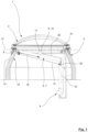
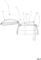
- the embodiment shown in the Figures 1 to 9 comprises a room closure device 1 according to the invention, which comprises a top ring 2 and a room closure element 3.
- the top ring 2 is formed here by a four-sided body, which has four straight side walls 16.
- the side walls 16 each define an edge 15 of the top ring 2.
- the top ring 2 On an upper end face, the top ring 2 has a circumferential sealing surface, which is arranged within a sealing plane 13.
- the room closure element 3, which in the Figure 1 shown position in its closed position, rests on the curb 2 in such a way that it interacts with the latter to form a seal. In this way, a fluidic connection between a room that is separated from the environment by the room closure device 1 and the environment is interrupted.
- the room closure element 3 seals airtight with the curb 2 .
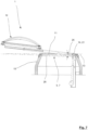
- the room closure element 3 interacts with a drive 4.
- the latter is formed here by an electric drive unit, by means of which a pressure force can be exerted.
- the drive 4 interacts here directly with two transmission devices 5 , by means of which the force caused by the drive 4 can be transmitted to the room closure element 3.
- the transmission devices 5 are each formed here by a pivot arm 7 and are therefore each in one piece, with a respective pivot arm 7 being arranged on an edge 15 of the curb 2 to form a common pivot axis 8. In the example, this is done by means of mounting brackets that are attached to the curb 2 in a force-transmitting manner.
- the mounting brackets interact with the pivot arms 7.
- the pivot arms 7 are arranged on both sides of the room closure element 3 .
- An engagement point of the drive 4 on a respective swivel arm 7 is located at a distance from the swivel axis 8, so that the engagement point is arranged under a lever arm 10 relative to the swivel axis 8. In this way, by operating the drive 4 , it is possible to swivel the swivel arms 7 about the swivel axis 8.
- each of the swivel arms 7 with its own drive 4 ; in a particularly advantageous manner, however, a force provided by a drive 4 is distributed between both swivel arms 7 or only one of the swivel arms 7 is moved directly by means of the drive 4.
- the respective In the latter configuration, the other swivel arm 7 is dragged along over the room closure element 3.
- the description given below refers only to one of the swivel arms 7, but in principle concerns both swivel arms 7 in its design.
- the swivel arm 7 is connected to the room-closing element 3 by means of a coupling means 9 in a force-transmitting manner. This means that a movement of the swivel arm 7 also directly causes a movement of the room-closing element 3.
- the coupling means 9 is designed here as a tab 17 , which interacts with the room-closing element 3 to form a rotation axis 19.
- the swivel arms 7 are each straight and each have a longitudinal axis 26.
- the coupling means 9 of both swivel arms 7 each have a rotation axis 19 about which the room-closing element 3 can be rotated relative to the swivel arm 7.
- the coupling means 9 are positioned in the same way on both swivel arms 7 , so that the rotation axes 19 of both coupling means 9 match.
- the "common rotation axis" 19 is advantageously arranged parallel to the swivel axis 8 of the room-closing element 3 .
- a distance 18 at which the coupling means 9 is arranged on the swivel arm 7 corresponds in the example shown to approximately 50% of the total length of the swivel arm 7.
- This positioning means that the room closure element 3 does not rotate about the axis of rotation 19 solely due to its weight, but can at least essentially maintain its rotational position during the movement of the swivel arms 7.
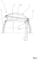
- the room closure element 3 in the example shown is connected to the upstand 2 along an edge 27 , the room closure element 3 is moved into a Figure 2 shown inclined coupling position.
- the swivel arm 7 When this coupling position is reached, the swivel arm 7 is coupled to a movement frame 11 of the space-closing element 3 by means of a coupling means 21 arranged at its end facing away from the swivel axis 8 , so that the movement frame 11 and the swivel arm 7 are connected to one another at the location of the coupling means 21. Until the coupling position is reached, the space-closing element 3 can be rotated about the rotation axis 19 relative to the swivel arm 7 .
- the coupling means 21 arranged at the ends of the pivot arms 7 facing away from the pivot axis 8 are each formed by a mechanical locking lock.
- the coupling means 21 is suitable for interacting in a form-fitting manner with a complementary coupling means of the movement frame 11 of the space-closing element 3 and in this way producing a force-transmitting, non-destructively releasable coupling.
- the design of the room closure element 3 with a movement frame 11 is particularly advantageous.
- the latter is in direct engagement with the swivel arms 7.
- the coupling means of the room closure element 3, which interacts with the coupling means 21 of a respective swivel arm 7 is formed on the movement frame 11.
- this movement frame 11 is equipped with two telescopic rails, with one of the telescopic rails interacting with one of the swivel arms 7.
- the fixation of the movement frame 11 to the swivel arms 7 by means of two coupling means 9, 21 serves to enable a torque-transmitting bearing of the room closure element 3 on the swivel arms 7 , which prevents uncontrolled rotation of the room closure element 3 relative to the swivel arms 7.
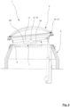
- FIGS 4 and 5 illustrate the room closure element 3 , firstly with the swivel arms 7 in their pre-position and finally in their deflection position, from which the room closure element 3 can be transferred to its RWA position.
- the latter is shown in Figure 5
- the coupling in a torque-transmitting manner is necessary because the room closure element 3 would otherwise rotate about its axis of rotation 19 relative to the pivot arms 7 on the pivot axis 8. In the example shown, this would prevent the room closure element 3 from being transferred to its RWA position.
- the flow cross-section 6 between the environment and the room is maximally released, so that in particular emergency ventilation of the room can take place.
- This "maximum release" of the flow cross-section 6 consists in the fact that a cross-section of the curb 2 in the area of the sealing plane 13 is completely released and is therefore completely available as flow cross-section 6. Ventilation of the room is therefore just as possible in this state as if the room closure element 3 were not present.
- This type of emergency ventilation is primarily important in the event of a fire.
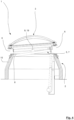
- the swivel arms 7 are moved by means of the drive 4 starting from the Figure 3 shown intermediate position further pivoted about the pivot axis 8 , so that the pivot arms 7 together with the space closure element 3 are transferred into an increasingly inclined position.
- the space closure element 3 is oriented at an angle to the sealing plane 13.
- the pivot arms 7 are deflected until the angle mentioned assumes the value of a limit angle 24. This is in Figure 5 illustrated.
- this limit angle 24 is reached, the pivot arms 7 are in their deflection position, with the space-closing element 3 being arranged at an angle such that a surface part 12 of the same can move translationally relative to the pivot arms 7 solely due to its weight.
- Such a movement is made possible by means of the movement frame 11 , which has the telescopic rails described above.
- a locking means 14 of the room closure element 3 is now released, whereby the surface part 12 is decoupled from the movement frame 11 and can move relative to the latter.
- the surface part 12 - driven solely by its weight - moves translationally relative to the swivel arms 7 so that it is completely “moved out” of an opening area of the curb 2.
- the flow cross-section 6 between the room and the environment is thus completely released, so that air can flow unhindered, particularly from the room in a vertical direction upwards into the environment.
- the flow cross-section 6 essentially corresponds to an opening cross-section of the curb 2.
- the locking means 14 is advantageously coupled to the respective pivot arm 7 in such a way that it automatically releases the translational movement between the surface part 12 and the movement frame 11 as soon as the pivot arms 7 are pivoted about the pivot axis 8 by such an amount that the space-closing element 3 is arranged relative to the sealing plane 13 , forming the limit angle 24.
- the pivot arms 7 are then in their respective deflection position.
- the total stroke by which a piston 22 of the drive 4 must be extended from the associated cylinder 23 is particularly small compared to the prior art, since the room closure element 3 in particular does not have to be pivoted by 90° or more relative to the sealing plane 13.
- the smaller pivot angle means that the movement of the room closure element 3 can be significantly shorter overall, which means that the total time for transferring the room closure element 3 from its closed position to its RWA position is significantly shorter than is possible in the prior art.
- the drive 4 can be dimensioned considerably smaller than in the prior art, which also results in a cost advantage.
- the room closure element 3 After the room closure element 3 has been moved into its RWA position, it may be of interest to move it back into its closed position.
- a fire alarm that initiated the movement of the room closure element 3 may have been a false alarm, after which the original state of the room closure device 1 should be restored. In the current state of technology, this is often not even possible, since the transfer of the respective room closure element 3 into its RWA position is not non-destructive.
- the return of the room closure element 3 is particularly easy. This is particularly evident from the Figures 7 to 9 .
- the swivel arms 7 are swiveled back around the swivel axis 8 by means of the drive 4 until the longitudinal axes 26 of the swivel arms 7 are arranged at an angle 25 relative to the horizontal sealing plane 13.
- the swivel arms 7 are then in their Back position.
- the angle 25 between the longitudinal axis 26 and the sealing plane 13 when the swivel arms 7 are in this return position is negative in relation to the sealing plane 13 , while the limit angle 24 described above is positive when the swivel arms 7 are in their deflection position.
- the inclination of the swivel arms 7 in their return position means that the weight of the surface part 12 has a horizontal component in the direction of the curb 2. This in turn means that the surface part 12 is moved back from its emergency position to its normal position by means of the movement frame 11 solely by the effect of gravity. The result of this process can be seen particularly well from Figure 8 recognizable.
- the room closure element 3 is then placed back into its sealing seat in the desired manner, so that the room closure element 3 seals against the curb 2 at least in a rainproof, preferably airtight manner. Consequently, the room closure element 3 is ultimately back in its closed position, which is made up of Figure 9
- the room closure element 3 is first placed with its one edge 27 on the upstand 2.
- the edge 27 is then coupled to the upstand 2 in a force-transmitting manner and at the same time the coupling means 21 for connecting the swivel arms 7 and the movement frame 11 is released.
- the swivel arms 7 can now be swiveled again relative to the movement frame 11 about the axis of rotation 9.
- the room closure element 3 is at this moment in the Figure 2
- the alignment shown in Figure 9 shown closing position is reached.
Landscapes
- Engineering & Computer Science (AREA)
- Mechanical Engineering (AREA)
- Chemical & Material Sciences (AREA)
- Combustion & Propulsion (AREA)
- General Engineering & Computer Science (AREA)
- Architecture (AREA)
- Civil Engineering (AREA)
- Structural Engineering (AREA)
- Business, Economics & Management (AREA)
- Emergency Management (AREA)
- Specific Sealing Or Ventilating Devices For Doors And Windows (AREA)
Claims (16)
- Système de fermeture de local (1) pouvant être ouvert, en particulier un dôme lumineux, pour la fermeture d'un local contre un environnement, comprenant :- une costière (2),- un élément de fermeture de local (3),- un système d'entraînement (4),- ainsi qu'au moins un système de transmission (5),sachant que l'élément de fermeture de local (3) peut être déplacé au moyen du système d'entraînement (4) par rapport à la costière (2),sachant qu'une force d'entraînement mise à disposition par le système d'entraînement (4) peut être transmise au moyen du système de transmission (5) à l'élément de fermeture de local (3),sachant que l'élément de fermeture de local (3) est en contact périphérique avec la costière (2) en cas d'une position de fermeture de telle manière qu'il ferme le local au moins de façon étanche à la pluie envers l'environnement,sachant que l'élément de fermeture de local (3) en cas d'une position d'évacuation des fumées et de chaleur [EFC] est éloigné de la costière (2) de telle manière qu'une section d'écoulement (6), qui forme une liaison fluidique entre le local et l'environnement, est libérée au maximum,sachant que le système de transmission (5) comprend au moins un bras pivotant allongé (7), qui est logé sur la costière (2) pouvant pivoter autour d'un axe de pivotement (8),sachant qu'au moins un moyen de couplage (9), au moyen duquel l'élément de fermeture de local (3) et le bras pivotant (7) sont reliés entre eux en transmission de force, est disposé à une distance de l'axe de pivotement (8),sachant que le système d'entraînement (4) vient en prise sur le bras pivotant (7) en constituant un bras de levier (10) en référence à l'axe pivotant (8) de telle sorte que le bras pivotant (7) peut pivoter autour de l'axe pivotant (8) au moyen du système d'entraînement (4),caractérisé en ce quel'élément de fermeture de local (3) comprend au moins un cadre de déplacement (11) au moyen duquel au moins une partie superficielle (12) de l'élément de fermeture de local (3) peut être déplacé par rapport au bras pivotant (7),sachant que le cadre de déplacement (11) comprend au moins un système de rail,sachant qu'au moins la partie superficielle (12) de l'élément de fermeture de local (3) peut être déplacée de façon translatoire par rapport au bras pivotant (7) au moyen du système de rail.
- Système de fermeture de local (1) selon la revendication 1, caractérisé en ce que l'élément de fermeture de local (3) et le bras pivotant (7) sont reliés entre eux en présence de l'élément de fermeture de local (3) dans la position EFC de celui-ci.
- Système de fermeture de local (1) selon l'une quelconque des revendications précédentes, caractérisé en ce que le système de rail du cadre de déplacement (11) est constitué sous la forme d'un rail télescopique.
- Système de fermeture de local (1) selon l'une quelconque des revendications précédentes, caractérisé en ce que l'élément de fermeture de local (3) peut être transféré dans sa position EFC au moyen d'un mouvement de sa partie superficielle (12) par rapport au bras pivotant (7), de préférence exclusivement au moyen de l'effet d'une force de gravité de la partie superficielle (12).
- Système de fermeture de local (1) selon l'une quelconque des revendications précédentes, caractérisé en ce que la partie superficielle (12) peut être déplacé à nouveau entre une position normale correspondant à la position de fermeture de l'élément de fermeture de local (3) et une position d'urgence correspondant à la position EFC de l'élément de fermeture de local (3).
- Système de fermeture de local (1) selon l'une quelconque des revendications précédentes, caractérisé en ce que le bras pivotant (7) en présence de l'élément de fermeture de local (3) dans la position EFC de celui-ci, se trouve dans une position de débattement tournée autour de l'axe pivotant (8) de telle manière qu'au moins une partie du bras pivotant (7) fait saillie vers l'extérieur sur un plan d'étanchéité (13) de la costière (2), sachant de préférence qu'au moins une section (20) du bras pivotant (7) est orientée inclinée par rapport au plan d'étanchéité (13).
- Système de fermeture de local (1) selon la revendication 6, caractérisé en ce que l'élément de fermeture de local (3) comprend au moins un moyen d'encliquetage (14), qui évite un mouvement translatoire de la partie superficielle (12) par rapport au bras pivotant (7) au moins tant que le bras pivotant (7) est dans sa position de débattement, sachant de préférence qu'en atteignant la position de débattement, le moyen d'encliquetage (14) libère automatiquement le mouvement de la partie superficielle (12).
- Système de fermeture de local selon la revendication 6 ou 7, caractérisé en ce que le bras pivotant (7) peut être déplacé dans une position de retour en partant de sa position de débattement en présence de laquelle au moins une section (20) du bras pivotant (7) est orientée inversement inclinée par rapport au plan d'étanchéité (13) de la costière (2) en comparaison de la position de débattement de telle sorte de préférence que la partie superficielle (12) de l'élément de fermeture de local (3) peut être exclusivement déplacée de la position d'urgence de celui-ci en retour dans la position normale de celui-ci qu'au moyen de l'effet de la force de gravité de la partie superficielle (12).
- Système de fermeture de local (1) selon l'une quelconque des revendications précédentes, caractérisé par au moins un système de verrouillage, au moyen duquel au moins une partie de l'élément de fermeture de local (3) peut être verrouillée à la costière (2) de telle manière que l'élément de fermeture de local (3) peut être soulevé seulement en partie de la costière (2) au cours du transfert de sa position de fermeture en direction d'une position d'ouverture au moins dans une première section de déplacement de l'élément de fermeture de local (3).
- Système de fermeture de local (1) selon la revendication 9, caractérisé en ce que le système de verrouillage coopère avec un bord (27) de l'élément de fermeture de local (3) tourné vers le système d'entraînement (4) de telle manière que l'élément de fermeture de local (3) se sépare de la costière (2) au cours du soulèvement du bras pivotant (7) d'abord sur le côté éloigné du système d'entraînement (4).
- Système de fermeture de local (1) selon l'une quelconque des revendications précédentes, caractérisé en ce que le bras pivotant (7) et l'élément de fermeture de local (3) sont reliés entre eux au moins en présence de l'élément de fermeture de local (3) dans sa position de fermeture exclusivement à un endroit au moyen d'un moyen de couplage (9), de préférence en constituant un axe de rotation (19) de telle manière que l'élément de fermeture de local (3) peut être tourné au cours d'un soulèvement du bras pivotant (7) au moyen du système d'entraînement (4) par rapport au bras pivotant (7).
- Système de fermeture de local (1) selon l'une quelconque des revendications précédentes, caractérisé en ce que le bras pivotant (7) comporte au moins un autre moyen de couplage (21), au moyen duquel l'élément de fermeture de local (3) et le bras pivotant (7) peuvent être reliés entre eux en plus du premier moyen de couplage (9) cité.
- Procédé d'ouverture d'un système de fermeture de local (1) pour la fermeture d'un local contre un environnement, le système de fermeture de local (1) comprenant :- une costière (2),- un élément de fermeture de local (3),- un système d'entraînement (4),- ainsi qu'au moins un système de transmission (5),sachant que l'élément de fermeture de local (3) peut être déplacé au moyen du système d'entraînement (4) par rapport à la costière (2),sachant qu'une force d'entraînement mise à disposition par le système d'entraînement (4) peut être transmise au moyen du système de transmission (5) à l'élément de fermeture de local (3),sachant que l'élément de fermeture de local (3) est en contact périphérique avec la costière (2) en cas d'une position de fermeture de telle manière qu'il ferme le local au moins de façon étanche à la pluie envers l'environnement,sachant que l'élément de fermeture de local (3) en cas de présence dans une position EFC est éloigné de la costière (2) de telle manière qu'une section transversale d'écoulement (6), qui forme une liaison fluidique entre le local et l'environnement, est libérée au maximum,sachant que le système de transmission (5) comprend au moins un bras pivotant allongé (7), qui est logé sur la costière (2) pouvant pivoter autour d'un axe pivotant (8),sachant qu'au moins un moyen de couplage (9), au moyen duquel l'élément de fermeture de local (3) et le bras pivotant (7) sont reliés entre eux en transmission de force, est disposé à une distance de l'axe de pivotement (8),sachant que le système d'entraînement (4) vient en prise sur le bras pivotant (7) en constituant un bras de levier (10) en référence à l'axe de pivotement (8) de telle sorte que le bras pivotant (7) peut pivoter autour de l'axe de pivotement (8) au moyen du système d'entraînement (4),sachant que l'élément de fermeture de local (3) comprend au moins un cadre de déplacement (11) au moyen duquel au moins une partie superficielle (12) de l'élément de fermeture de local (3) peut être déplacée par rapport au bras pivotant (7),sachant que le cadre de déplacement (11) comprend au moins un système de rail,sachant qu'au moins la partie superficielle (12) de l'élément de fermeture de local (3) peut être déplacée de façon translatoire par rapport au bras pivotant (7) au moyen du système de rail,le procédé comprenant les étapes de procédé suivantes :a) l'élément de fermeture de local (3) est déplacé au moyen du système d'entraînement (4) en partant d'une position de fermeture par rapport à la costière (2), l'élément de fermeture de local (3) étant soulevé au moins en partie de son siège étanche constitué sur la costière (2) de telle manière que la section transversale d'écoulement (6) entre le local et l'environnement est libérée,b) l'élément de fermeture de local (3) est éloigné de la costière (2) de telle manière qu'elle se trouve dans sa position d'évacuation des fumées et de la chaleur (EFC) dans laquelle la section transversale d'écoulement (6) est libérée au maximum,c) l'élément de fermeture de local (3) est soulevé au moins en partie de son siège étanche, dans une première section de déplacement en partant de sa position de fermeture,d) l'élément de fermeture de local (3) est tourné dans une deuxième section de déplacement par rapport à la costière (2) jusqu'à ce que l'élément de fermeture de local (3) se trouve dans une position intermédiaire,e) en partant de la position intermédiaire, au moins une partie superficielle (12) de l'élément de fermeture de local (3) est déplacée de façon translatoire par rapport à la costière (2) jusqu'à ce que l'élément de fermeture de local (3) se trouve dans sa position EFC,caractérisé en ce quela partie superficielle (12) est déplacée de façon translatoire au moyen du système de rail par rapport au bras pivotant (7).
- Procédé selon la revendication 13, caractérisé en ce que l'élément de fermeture de local (3) pendant la première section de déplacement est verrouillé, sur la costière (2) au moins en partie, de préférence le long d'un bord (27) de la costière (2) de telle manière que l'élément de fermeture de local (3) pendant la première section de déplacement est soulevée seulement en partie de la costière (2).
- Procédé selon la revendication 13 ou 14, caractérisé en ce que le bras pivotant (7) est verrouillé contre l'élément de fermeture de local (3) de telle manière que l'élément de fermeture de local (3) ne peut pas être transféré dans sa position EFC sans déverrouillage préalable, sachant de préférence que le verrouillage du bras pivotant (7) contre l'élément de fermeture de local (3) a lieu simultanément à un déverrouillage de l'élément de fermeture de local (3) de la costière (2).
- Procédé selon l'une quelconque des revendications 13 à 15, caractérisé en ce que l'élément de fermeture de local (3) est transféré de sa position d'évacuation de fumées et de chaleur (EFC) en direction de sa position de fermeture exclusivement au moyen de l'effet de la force de gravité, sachant de préférence qu'au moins la partie superficielle (12) de l'élément de fermeture de local (3) peut être déplacée de cette manière d'une position d'urgence correspondant à la position EFC de l'élément de fermeture de local (3) dans une position normale correspondant à la position de fermeture de l'élément de fermeture de local (3).
Applications Claiming Priority (2)
| Application Number | Priority Date | Filing Date | Title |
|---|---|---|---|
| DE102018115783.5A DE102018115783A1 (de) | 2018-06-29 | 2018-06-29 | Öffenbare Raumabschlusseinrichtung sowie Verfahren zu deren Öffnung |
| DE102018132222.4A DE102018132222A1 (de) | 2018-12-14 | 2018-12-14 | Öffenbare Raumabschlusseinrichtung sowie Verfahren zu deren Öffnung |
Publications (2)
| Publication Number | Publication Date |
|---|---|
| EP3587696A1 EP3587696A1 (fr) | 2020-01-01 |
| EP3587696B1 true EP3587696B1 (fr) | 2024-12-11 |
Family
ID=67105877
Family Applications (1)
| Application Number | Title | Priority Date | Filing Date |
|---|---|---|---|
| EP19182886.2A Active EP3587696B1 (fr) | 2018-06-29 | 2019-06-27 | Dispositif de fermeture d'espace pouvant être ouvert ainsi que son procédé d'ouverture |
Country Status (1)
| Country | Link |
|---|---|
| EP (1) | EP3587696B1 (fr) |
Family Cites Families (6)
| Publication number | Priority date | Publication date | Assignee | Title |
|---|---|---|---|---|
| BE664961A (fr) * | 1964-06-05 | 1965-10-01 | ||
| DE2412154B2 (de) * | 1973-04-21 | 1977-06-16 | Göbel, Klaus, 5500 Trier | Auf einem rahmen angeordnete, in der ebene des rahmens verschiebbare lichtkuppel |
| DE8808856U1 (de) * | 1988-07-09 | 1988-08-25 | Grescha-Gesellschaft mbH & Co Grefe & Scharf, 4817 Leopoldshöhe | Rauchabzugs- und Lüftungsklappe |
| DE29921090U1 (de) * | 1999-12-01 | 2001-04-12 | Stürmann GmbH & Co., 40699 Erkrath | Rauchabzugs- oder Lüftungsklappe |
| BE1014531A5 (nl) * | 2001-12-07 | 2003-12-02 | Plastics N V Ag | Inrichting voor het openen van ontluchtingskoepels voor rook-en warmteafvoer en verluchting. |
| DE102009059107B4 (de) * | 2009-12-18 | 2011-09-01 | Andreas Grasl | Gelenkanordnung zur Betätigung einer Klappe, insbesondere Entrauchungsklappe |
-
2019
- 2019-06-27 EP EP19182886.2A patent/EP3587696B1/fr active Active
Also Published As
| Publication number | Publication date |
|---|---|
| EP3587696A1 (fr) | 2020-01-01 |
Similar Documents
| Publication | Publication Date | Title |
|---|---|---|
| EP2712380B1 (fr) | Dispositif écarteur pour portes et abattants de véhicules automobiles | |
| EP3243997B1 (fr) | Issue de secours | |
| WO2001055543A1 (fr) | Porte relevable par sections ou porte accordeon | |
| EP3822438B1 (fr) | Serrure automatique | |
| EP3643849B1 (fr) | Ouverture de toit, de plafond ou de façade | |
| EP3587696B1 (fr) | Dispositif de fermeture d'espace pouvant être ouvert ainsi que son procédé d'ouverture | |
| DE102011085177A1 (de) | Antriebssystem für ein KFZ-Dachsystem | |
| DE3604083A1 (de) | Feststellvorrichtung fuer tuerfluegel mit einem tuerschliesser | |
| DE102018121305A1 (de) | Flugzeugtür, Flugzeugbereich und Flugzeug mit einer Flugzeugtür | |
| AT521543B1 (de) | Schutzvorrichtung für Roll- und Sektionaltore | |
| DE102004061161B4 (de) | Isolieraufbau für ein Fahrzeug | |
| DE102018132222A1 (de) | Öffenbare Raumabschlusseinrichtung sowie Verfahren zu deren Öffnung | |
| DE102019112336B4 (de) | Türeinheit für ein Fahrzeug | |
| DE8302361U1 (de) | Vorrichtung zum Be- und Entlüften von Räumen und zum Abzug von Rauch und Wärme aus Räumen | |
| DE3302887A1 (de) | Vorrichtung zum be- und entlueften von raeumen und zum abzug von rauch und waerme aus raeumen | |
| EP0744516B1 (fr) | Système de verrouillage pour porte | |
| EP3822437A1 (fr) | Système de fenêtre ou de porte | |
| DE2646844A1 (de) | Verriegelung fuer schleusentueren | |
| DE102018115783A1 (de) | Öffenbare Raumabschlusseinrichtung sowie Verfahren zu deren Öffnung | |
| EP4441320B1 (fr) | Fenêtre ou porte | |
| EP4237649B1 (fr) | Fermeture dotée d'un dispositif de clapet | |
| DE19713298C1 (de) | Vorrichtung zum Öffnen und Schließen einer Klappe | |
| DE19607234A1 (de) | Beschlag für einen um eine horizontale Achse schwenkbaren Flügel | |
| DE102018118088A1 (de) | Schutzvorrichtung für Roll- und Sektionaltore | |
| DE29507084U1 (de) | Hydraulisch betätigbare Rückwand |
Legal Events
| Date | Code | Title | Description |
|---|---|---|---|
| PUAI | Public reference made under article 153(3) epc to a published international application that has entered the european phase |
Free format text: ORIGINAL CODE: 0009012 |
|
| STAA | Information on the status of an ep patent application or granted ep patent |
Free format text: STATUS: THE APPLICATION HAS BEEN PUBLISHED |
|
| AK | Designated contracting states |
Kind code of ref document: A1 Designated state(s): AL AT BE BG CH CY CZ DE DK EE ES FI FR GB GR HR HU IE IS IT LI LT LU LV MC MK MT NL NO PL PT RO RS SE SI SK SM TR |
|
| AX | Request for extension of the european patent |
Extension state: BA ME |
|
| STAA | Information on the status of an ep patent application or granted ep patent |
Free format text: STATUS: REQUEST FOR EXAMINATION WAS MADE |
|
| 17P | Request for examination filed |
Effective date: 20200624 |
|
| RBV | Designated contracting states (corrected) |
Designated state(s): AL AT BE BG CH CY CZ DE DK EE ES FI FR GB GR HR HU IE IS IT LI LT LU LV MC MK MT NL NO PL PT RO RS SE SI SK SM TR |
|
| RAP1 | Party data changed (applicant data changed or rights of an application transferred) |
Owner name: VKR HOLDING A/S |
|
| STAA | Information on the status of an ep patent application or granted ep patent |
Free format text: STATUS: EXAMINATION IS IN PROGRESS |
|
| 17Q | First examination report despatched |
Effective date: 20230621 |
|
| RIC1 | Information provided on ipc code assigned before grant |
Ipc: E05D 15/58 20060101ALI20240719BHEP Ipc: E05F 15/63 20150101ALI20240719BHEP Ipc: E05F 15/72 20150101ALI20240719BHEP Ipc: F24F 11/34 20180101ALI20240719BHEP Ipc: F24F 7/02 20060101ALI20240719BHEP Ipc: E04D 13/035 20060101AFI20240719BHEP |
|
| GRAP | Despatch of communication of intention to grant a patent |
Free format text: ORIGINAL CODE: EPIDOSNIGR1 |
|
| STAA | Information on the status of an ep patent application or granted ep patent |
Free format text: STATUS: GRANT OF PATENT IS INTENDED |
|
| INTG | Intention to grant announced |
Effective date: 20240830 |
|
| GRAS | Grant fee paid |
Free format text: ORIGINAL CODE: EPIDOSNIGR3 |
|
| GRAA | (expected) grant |
Free format text: ORIGINAL CODE: 0009210 |
|
| STAA | Information on the status of an ep patent application or granted ep patent |
Free format text: STATUS: THE PATENT HAS BEEN GRANTED |
|
| AK | Designated contracting states |
Kind code of ref document: B1 Designated state(s): AL AT BE BG CH CY CZ DE DK EE ES FI FR GB GR HR HU IE IS IT LI LT LU LV MC MK MT NL NO PL PT RO RS SE SI SK SM TR |
|
| REG | Reference to a national code |
Ref country code: GB Ref legal event code: FG4D Free format text: NOT ENGLISH |
|
| REG | Reference to a national code |
Ref country code: CH Ref legal event code: EP |
|
| REG | Reference to a national code |
Ref country code: IE Ref legal event code: FG4D Free format text: LANGUAGE OF EP DOCUMENT: GERMAN |
|
| REG | Reference to a national code |
Ref country code: DE Ref legal event code: R096 Ref document number: 502019012630 Country of ref document: DE |
|
| REG | Reference to a national code |
Ref country code: LT Ref legal event code: MG9D |
|
| PG25 | Lapsed in a contracting state [announced via postgrant information from national office to epo] |
Ref country code: HR Free format text: LAPSE BECAUSE OF FAILURE TO SUBMIT A TRANSLATION OF THE DESCRIPTION OR TO PAY THE FEE WITHIN THE PRESCRIBED TIME-LIMIT Effective date: 20241211 |
|
| PG25 | Lapsed in a contracting state [announced via postgrant information from national office to epo] |
Ref country code: FI Free format text: LAPSE BECAUSE OF FAILURE TO SUBMIT A TRANSLATION OF THE DESCRIPTION OR TO PAY THE FEE WITHIN THE PRESCRIBED TIME-LIMIT Effective date: 20241211 |
|
| PG25 | Lapsed in a contracting state [announced via postgrant information from national office to epo] |
Ref country code: BG Free format text: LAPSE BECAUSE OF FAILURE TO SUBMIT A TRANSLATION OF THE DESCRIPTION OR TO PAY THE FEE WITHIN THE PRESCRIBED TIME-LIMIT Effective date: 20241211 |
|
| REG | Reference to a national code |
Ref country code: NL Ref legal event code: MP Effective date: 20241211 |
|
| PG25 | Lapsed in a contracting state [announced via postgrant information from national office to epo] |
Ref country code: ES Free format text: LAPSE BECAUSE OF FAILURE TO SUBMIT A TRANSLATION OF THE DESCRIPTION OR TO PAY THE FEE WITHIN THE PRESCRIBED TIME-LIMIT Effective date: 20241211 |
|
| PG25 | Lapsed in a contracting state [announced via postgrant information from national office to epo] |
Ref country code: NO Free format text: LAPSE BECAUSE OF FAILURE TO SUBMIT A TRANSLATION OF THE DESCRIPTION OR TO PAY THE FEE WITHIN THE PRESCRIBED TIME-LIMIT Effective date: 20250311 |
|
| PG25 | Lapsed in a contracting state [announced via postgrant information from national office to epo] |
Ref country code: LV Free format text: LAPSE BECAUSE OF FAILURE TO SUBMIT A TRANSLATION OF THE DESCRIPTION OR TO PAY THE FEE WITHIN THE PRESCRIBED TIME-LIMIT Effective date: 20241211 Ref country code: GR Free format text: LAPSE BECAUSE OF FAILURE TO SUBMIT A TRANSLATION OF THE DESCRIPTION OR TO PAY THE FEE WITHIN THE PRESCRIBED TIME-LIMIT Effective date: 20250312 |
|
| PG25 | Lapsed in a contracting state [announced via postgrant information from national office to epo] |
Ref country code: RS Free format text: LAPSE BECAUSE OF FAILURE TO SUBMIT A TRANSLATION OF THE DESCRIPTION OR TO PAY THE FEE WITHIN THE PRESCRIBED TIME-LIMIT Effective date: 20250311 |
|
| PG25 | Lapsed in a contracting state [announced via postgrant information from national office to epo] |
Ref country code: NL Free format text: LAPSE BECAUSE OF FAILURE TO SUBMIT A TRANSLATION OF THE DESCRIPTION OR TO PAY THE FEE WITHIN THE PRESCRIBED TIME-LIMIT Effective date: 20241211 |
|
| PG25 | Lapsed in a contracting state [announced via postgrant information from national office to epo] |
Ref country code: SM Free format text: LAPSE BECAUSE OF FAILURE TO SUBMIT A TRANSLATION OF THE DESCRIPTION OR TO PAY THE FEE WITHIN THE PRESCRIBED TIME-LIMIT Effective date: 20241211 |
|
| PG25 | Lapsed in a contracting state [announced via postgrant information from national office to epo] |
Ref country code: PL Free format text: LAPSE BECAUSE OF FAILURE TO SUBMIT A TRANSLATION OF THE DESCRIPTION OR TO PAY THE FEE WITHIN THE PRESCRIBED TIME-LIMIT Effective date: 20241211 |
|
| PGFP | Annual fee paid to national office [announced via postgrant information from national office to epo] |
Ref country code: DE Payment date: 20250507 Year of fee payment: 7 |
|
| PG25 | Lapsed in a contracting state [announced via postgrant information from national office to epo] |
Ref country code: IS Free format text: LAPSE BECAUSE OF FAILURE TO SUBMIT A TRANSLATION OF THE DESCRIPTION OR TO PAY THE FEE WITHIN THE PRESCRIBED TIME-LIMIT Effective date: 20250411 |
|
| PG25 | Lapsed in a contracting state [announced via postgrant information from national office to epo] |
Ref country code: PT Free format text: LAPSE BECAUSE OF FAILURE TO SUBMIT A TRANSLATION OF THE DESCRIPTION OR TO PAY THE FEE WITHIN THE PRESCRIBED TIME-LIMIT Effective date: 20250411 |
|
| PG25 | Lapsed in a contracting state [announced via postgrant information from national office to epo] |
Ref country code: EE Free format text: LAPSE BECAUSE OF FAILURE TO SUBMIT A TRANSLATION OF THE DESCRIPTION OR TO PAY THE FEE WITHIN THE PRESCRIBED TIME-LIMIT Effective date: 20241211 |
|
| PG25 | Lapsed in a contracting state [announced via postgrant information from national office to epo] |
Ref country code: RO Free format text: LAPSE BECAUSE OF FAILURE TO SUBMIT A TRANSLATION OF THE DESCRIPTION OR TO PAY THE FEE WITHIN THE PRESCRIBED TIME-LIMIT Effective date: 20241211 |
|
| PG25 | Lapsed in a contracting state [announced via postgrant information from national office to epo] |
Ref country code: SK Free format text: LAPSE BECAUSE OF FAILURE TO SUBMIT A TRANSLATION OF THE DESCRIPTION OR TO PAY THE FEE WITHIN THE PRESCRIBED TIME-LIMIT Effective date: 20241211 |
|
| PG25 | Lapsed in a contracting state [announced via postgrant information from national office to epo] |
Ref country code: CZ Free format text: LAPSE BECAUSE OF FAILURE TO SUBMIT A TRANSLATION OF THE DESCRIPTION OR TO PAY THE FEE WITHIN THE PRESCRIBED TIME-LIMIT Effective date: 20241211 |
|
| PG25 | Lapsed in a contracting state [announced via postgrant information from national office to epo] |
Ref country code: IT Free format text: LAPSE BECAUSE OF FAILURE TO SUBMIT A TRANSLATION OF THE DESCRIPTION OR TO PAY THE FEE WITHIN THE PRESCRIBED TIME-LIMIT Effective date: 20241211 |
|
| PG25 | Lapsed in a contracting state [announced via postgrant information from national office to epo] |
Ref country code: SE Free format text: LAPSE BECAUSE OF FAILURE TO SUBMIT A TRANSLATION OF THE DESCRIPTION OR TO PAY THE FEE WITHIN THE PRESCRIBED TIME-LIMIT Effective date: 20241211 |
|
| REG | Reference to a national code |
Ref country code: DE Ref legal event code: R097 Ref document number: 502019012630 Country of ref document: DE |
|
| PG25 | Lapsed in a contracting state [announced via postgrant information from national office to epo] |
Ref country code: DK Free format text: LAPSE BECAUSE OF FAILURE TO SUBMIT A TRANSLATION OF THE DESCRIPTION OR TO PAY THE FEE WITHIN THE PRESCRIBED TIME-LIMIT Effective date: 20241211 |
|
| PLBE | No opposition filed within time limit |
Free format text: ORIGINAL CODE: 0009261 |
|
| STAA | Information on the status of an ep patent application or granted ep patent |
Free format text: STATUS: NO OPPOSITION FILED WITHIN TIME LIMIT |
|
| 26N | No opposition filed |
Effective date: 20250912 |