EP3584571A1 - Verfahren und system zur verhinderung von taubildung und lichtstreuung in verbindung mit taubildung - Google Patents
Verfahren und system zur verhinderung von taubildung und lichtstreuung in verbindung mit taubildung Download PDFInfo
- Publication number
- EP3584571A1 EP3584571A1 EP18754010.9A EP18754010A EP3584571A1 EP 3584571 A1 EP3584571 A1 EP 3584571A1 EP 18754010 A EP18754010 A EP 18754010A EP 3584571 A1 EP3584571 A1 EP 3584571A1
- Authority
- EP
- European Patent Office
- Prior art keywords
- thin wire
- dew condensation
- liquid droplet
- metal
- light scattering
- Prior art date
- Legal status (The legal status is an assumption and is not a legal conclusion. Google has not performed a legal analysis and makes no representation as to the accuracy of the status listed.)
- Withdrawn
Links
Images


Classifications
-
- G—PHYSICS
- G02—OPTICS
- G02B—OPTICAL ELEMENTS, SYSTEMS OR APPARATUS
- G02B27/00—Optical systems or apparatus not provided for by any of the groups G02B1/00 - G02B26/00, G02B30/00
- G02B27/0006—Optical systems or apparatus not provided for by any of the groups G02B1/00 - G02B26/00, G02B30/00 with means to keep optical surfaces clean, e.g. by preventing or removing dirt, stains, contamination, condensation
-
- H—ELECTRICITY
- H05—ELECTRIC TECHNIQUES NOT OTHERWISE PROVIDED FOR
- H05B—ELECTRIC HEATING; ELECTRIC LIGHT SOURCES NOT OTHERWISE PROVIDED FOR; CIRCUIT ARRANGEMENTS FOR ELECTRIC LIGHT SOURCES, IN GENERAL
- H05B3/00—Ohmic-resistance heating
- H05B3/84—Heating arrangements specially adapted for transparent or reflecting areas, e.g. for demisting or de-icing windows, mirrors or vehicle windshields
-
- B—PERFORMING OPERATIONS; TRANSPORTING
- B60—VEHICLES IN GENERAL
- B60S—SERVICING, CLEANING, REPAIRING, SUPPORTING, LIFTING, OR MANOEUVRING OF VEHICLES, NOT OTHERWISE PROVIDED FOR
- B60S1/00—Cleaning of vehicles
- B60S1/02—Cleaning windscreens, windows or optical devices
- B60S1/04—Wipers or the like, e.g. scrapers
- B60S1/06—Wipers or the like, e.g. scrapers characterised by the drive
- B60S1/08—Wipers or the like, e.g. scrapers characterised by the drive electrically driven
- B60S1/0818—Wipers or the like, e.g. scrapers characterised by the drive electrically driven including control systems responsive to external conditions, e.g. by detection of moisture, dirt or the like
- B60S1/0822—Wipers or the like, e.g. scrapers characterised by the drive electrically driven including control systems responsive to external conditions, e.g. by detection of moisture, dirt or the like characterized by the arrangement or type of detection means
-
- G—PHYSICS
- G01—MEASURING; TESTING
- G01M—TESTING STATIC OR DYNAMIC BALANCE OF MACHINES OR STRUCTURES; TESTING OF STRUCTURES OR APPARATUS, NOT OTHERWISE PROVIDED FOR
- G01M3/00—Investigating fluid-tightness of structures
- G01M3/02—Investigating fluid-tightness of structures by using fluid or vacuum
- G01M3/04—Investigating fluid-tightness of structures by using fluid or vacuum by detecting the presence of fluid at the leakage point
-
- G—PHYSICS
- G01—MEASURING; TESTING
- G01N—INVESTIGATING OR ANALYSING MATERIALS BY DETERMINING THEIR CHEMICAL OR PHYSICAL PROPERTIES
- G01N27/00—Investigating or analysing materials by the use of electric, electrochemical, or magnetic means
- G01N27/26—Investigating or analysing materials by the use of electric, electrochemical, or magnetic means by investigating electrochemical variables; by using electrolysis or electrophoresis
- G01N27/416—Systems
-
- B—PERFORMING OPERATIONS; TRANSPORTING
- B60—VEHICLES IN GENERAL
- B60S—SERVICING, CLEANING, REPAIRING, SUPPORTING, LIFTING, OR MANOEUVRING OF VEHICLES, NOT OTHERWISE PROVIDED FOR
- B60S1/00—Cleaning of vehicles
- B60S1/02—Cleaning windscreens, windows or optical devices
- B60S1/04—Wipers or the like, e.g. scrapers
- B60S1/06—Wipers or the like, e.g. scrapers characterised by the drive
- B60S1/08—Wipers or the like, e.g. scrapers characterised by the drive electrically driven
- B60S1/0818—Wipers or the like, e.g. scrapers characterised by the drive electrically driven including control systems responsive to external conditions, e.g. by detection of moisture, dirt or the like
- B60S1/0822—Wipers or the like, e.g. scrapers characterised by the drive electrically driven including control systems responsive to external conditions, e.g. by detection of moisture, dirt or the like characterized by the arrangement or type of detection means
- B60S1/0825—Capacitive rain sensor
Definitions
- the present invention relates to a method for and a system for preventing dew condensation and light scattering due to the dew condensation.
- the method for preventing dew condensation there are methods of maintaining the dry state by performing dehumidification with constant heating, and a supply of gases such as dry air and dry nitrogen, however, these methods are methods of consuming energy for dehumidification even the dehumidification is not required, and therefore this is not preferable from the viewpoint of energy saving.
- the humidity sensor for example, a method is known, which detects humidity according to a change in the electric resistance value (impedance) or the capacitance of a sensor element (dryness and wetness responsive unit).
- a polymer membrane is used as a dryness and wetness responsive material for a sensor element, the response speed is faster (usually, several seconds to before and after 10 seconds) as compared with the electrical resistance-type humidity sensor, and the accuracy, reproducibility, and reliability are excellent.
- the production cost is high.
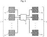
- the detection means comprises a plurality of at least one selected from the group consisting of the first thin wire and the second thin wire, and wherein the first thin wire extends from a first side towards a second side that is opposite to the first side and the second thin wire extends from the second side towards the first side such that the first thin wire and the second thin wire run in parallel.
- a system for preventing dew condensation including a detection means for detecting a fine liquid droplet, a removing means for removing the fine liquid droplet, and a control means for controlling the removing means on the basis of information from the detection means, wherein the detection means comprises a first thin wire made of a first metal, and a second thin wire made of a second metal or a semiconductor, the second metal being different from the first metal, wherein the first thin wire and the second thin wire are disposed in juxtaposition with each other on an insulating substrate, and wherein a spacing between the first thin wire and the second thin wire is in a range of 20 nm or more and 10000 nm or less.
- the insulating substrate is a silicon substrate with a silicon oxide film on its surface.
- n is a refractive index of a liquid droplet to the light, and when the liquid droplet is an approximately water droplet, the value is around 1.5 in the visible light region.
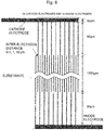
- Fig. 4 is a top view of the fine-liquid-droplet sensor 101
- Fig. 5 is a sectional view of a part connecting between A and A' in Fig. 4 .
- a galvanic current flows due to the galvanic action.
- Water has low conductivity and is insulative in a state of ultrapure water, however, if a minute amount of electrolytic component is contained by hydrogen ions and hydroxide ions, which are present at least at 10 -7 mol/L, respectively, a contamination, or the like, a measurable galvanic current flows in water in the use state.
- a spacing "d" between the first thin wire and the second thin wire is extremely important, and the spacing is required to be at least smaller than the size (diameter) of the liquid droplet to be detected for the prevention to the above problems.
- the lower limit of the spacing is determined by the size (diameter) of the liquid droplet to start the detection.
- the air may be configured to be allowed to flow between the first thin wire and the second thin wire while water is not attached to the sensor. More specifically, for example, by removing at least a part of positions corresponding to the gap between the thin wires, an opening portion passing through the front and rear sides of the substrate is arranged.
- a fine-liquid-droplet sensor 101 in which a cathode electrode made of gold (Au) as a first thin wire and an anode electrode made of copper (Cu) as a second thin wire were arranged in a comb shape on a silicon wafer with a silicon oxide film was produced.
- the laying density of the electrodes can be estimated as below.
- the laying widths are respectively 4n - 1 ⁇ m and 3n - 0.5 ⁇ m.
- the output becomes 11 times and 14 times as large, respectively. Since the S/N ratio of 1:100 or more is obtained even for the conventional measurement system, we can say that the experimentally produced sensor of the above embodiment can also perform the sensing without amplification or noise filtering.
- the width of the thin wire itself is configured to be narrower (thinner), the number of pairs for the same laying width is increased, allowing the output to be further improved.
- the fine-liquid-droplet detection sensor 101 detected the fine liquid droplet, and the air conditioner was started.
- Example 4 was an example in which a dew condensation prevention system produced in Example 2 was applied to a surveillance camera placed in the open air, and the details will be described below.
- hot air generated by a heater was used in place of the air conditioner as the fine-liquid-droplet removing means 3.
- This surveillance camera converts an image formed by an optical lens into a video signal by a complementary metal oxide semiconductor (CMOS) image sensor having sensitivity to visible light and near infrared light.
- CMOS complementary metal oxide semiconductor
- the optical lens was provided with a long hood such that water droplets due to rain or the like were not attached onto the optical lens.
- This surveillance camera was arranged in a place where the state was usually in a dry state but occasionally a fog was generated. Further, a light-emitting diode (LED) lamp and an infrared ray lamp were arranged in the place for the nighttime.
- LED light-emitting diode
Landscapes
- Physics & Mathematics (AREA)
- Life Sciences & Earth Sciences (AREA)
- Chemical & Material Sciences (AREA)
- Health & Medical Sciences (AREA)
- General Physics & Mathematics (AREA)
- Engineering & Computer Science (AREA)
- Biochemistry (AREA)
- Analytical Chemistry (AREA)
- Electrochemistry (AREA)
- General Health & Medical Sciences (AREA)
- Chemical Kinetics & Catalysis (AREA)
- Immunology (AREA)
- Pathology (AREA)
- Molecular Biology (AREA)
- Automation & Control Theory (AREA)
- Mechanical Engineering (AREA)
- Optics & Photonics (AREA)
- Investigating Or Analyzing Materials By The Use Of Fluid Adsorption Or Reactions (AREA)
- Investigating Or Analysing Materials By Optical Means (AREA)
Applications Claiming Priority (2)
| Application Number | Priority Date | Filing Date | Title |
|---|---|---|---|
| JP2017024629 | 2017-02-14 | ||
| PCT/JP2018/003512 WO2018150903A1 (ja) | 2017-02-14 | 2018-02-02 | 結露および結露に伴う光散乱の予防方法および予防システム |
Publications (2)
| Publication Number | Publication Date |
|---|---|
| EP3584571A1 true EP3584571A1 (de) | 2019-12-25 |
| EP3584571A4 EP3584571A4 (de) | 2020-12-16 |
Family
ID=63169933
Family Applications (1)
| Application Number | Title | Priority Date | Filing Date |
|---|---|---|---|
| EP18754010.9A Withdrawn EP3584571A4 (de) | 2017-02-14 | 2018-02-02 | Verfahren und system zur verhinderung von taubildung und lichtstreuung in verbindung mit taubildung |
Country Status (4)
| Country | Link |
|---|---|
| US (1) | US11856664B2 (de) |
| EP (1) | EP3584571A4 (de) |
| JP (1) | JP6786122B2 (de) |
| WO (1) | WO2018150903A1 (de) |
Families Citing this family (4)
| Publication number | Priority date | Publication date | Assignee | Title |
|---|---|---|---|---|
| WO2020100778A1 (ja) * | 2018-11-12 | 2020-05-22 | 国立研究開発法人物質・材料研究機構 | 結露検出素子 |
| WO2022196600A1 (ja) * | 2021-03-19 | 2022-09-22 | 国立研究開発法人物質・材料研究機構 | 熱中症、脱水症予兆警告システムおよび蒸散速度計測用デバイス |
| WO2023171472A1 (ja) * | 2022-03-09 | 2023-09-14 | 国立研究開発法人物質・材料研究機構 | 心拍変動測定システムおよび心拍変動測定方法 |
| KR102579168B1 (ko) * | 2022-09-30 | 2023-09-15 | 에스엘 주식회사 | 액적 제거장치 및 액적 제거방법 |
Family Cites Families (18)
| Publication number | Priority date | Publication date | Assignee | Title |
|---|---|---|---|---|
| AU5805873A (en) * | 1972-07-25 | 1975-01-16 | Koichi Sugaya | Humidity sensor electrode assembly |
| JPS6266719A (ja) | 1985-09-18 | 1987-03-26 | Yokogawa Electric Corp | リミツタ・アンプ |
| JP2992603B2 (ja) * | 1991-06-24 | 1999-12-20 | 日本電信電話株式会社 | ウォールジェット型電気化学的検出器およびその製造方法 |
| JP2001240146A (ja) * | 2000-02-29 | 2001-09-04 | Showa Shinku:Kk | 器具又は装置の結露を防止する方法 |
| JP2004500855A (ja) * | 2000-05-31 | 2004-01-15 | フラウンホファー ゲセルシャフトツール フェールデルンク ダー アンゲヴァンテン フォルシュンク エー.ファオ. | 感染モデル |
| JP2003098141A (ja) * | 2001-09-25 | 2003-04-03 | Mitsuba Corp | 露点測定装置およびその製造方法 |
| KR100442977B1 (ko) * | 2002-07-16 | 2004-08-04 | 현대모비스 주식회사 | 프런트 도어 글래스의 습기제거장치 |
| JP2004077297A (ja) * | 2002-08-19 | 2004-03-11 | Nippon Sheet Glass Co Ltd | 結露検出装置 |
| US9236622B2 (en) * | 2009-08-07 | 2016-01-12 | Ford Global Technologies, Llc | Fuel cell system with wetness sensor |
| JP2011041437A (ja) * | 2009-08-18 | 2011-02-24 | Toshiba Corp | 結露状態検出システム |
| JP5120966B2 (ja) | 2009-12-21 | 2013-01-16 | 独立行政法人産業技術総合研究所 | 極微量水分計測素子および該計測素子を用いた防湿封止性能評価方法 |
| US9796359B2 (en) * | 2012-02-23 | 2017-10-24 | The Raymond Corporation | Method and apparatus for removing and preventing lens surface contamination on a vehicle lens |
| CN102692432B (zh) * | 2012-05-29 | 2014-04-30 | 张家港丽恒光微电子科技有限公司 | 集成式湿度传感器及制造方法 |
| WO2015095800A1 (en) * | 2013-12-20 | 2015-06-25 | Lockheed Martin Corporation | Condensation inhibiting layer, method of forming the layer, and condensation inhibiting device |
| WO2016013544A1 (ja) | 2014-07-23 | 2016-01-28 | 国立研究開発法人物質・材料研究機構 | 高速応答・高感度乾湿応答センサー |
| CN105606668A (zh) * | 2015-12-21 | 2016-05-25 | 国网安徽省电力公司淮北供电公司 | 一种电化学式薄膜凝露传感器 |
| US11454603B2 (en) * | 2016-06-08 | 2022-09-27 | National Institute For Materials Science | Dew point measuring method and dew point measuring device |
| US20180113297A1 (en) * | 2016-10-21 | 2018-04-26 | Tanner Research, Inc. | Active droplet transport defogging |
-
2018
- 2018-02-02 US US16/483,815 patent/US11856664B2/en active Active
- 2018-02-02 EP EP18754010.9A patent/EP3584571A4/de not_active Withdrawn
- 2018-02-02 WO PCT/JP2018/003512 patent/WO2018150903A1/ja unknown
- 2018-02-02 JP JP2018568107A patent/JP6786122B2/ja active Active
Also Published As
| Publication number | Publication date |
|---|---|
| WO2018150903A1 (ja) | 2018-08-23 |
| EP3584571A4 (de) | 2020-12-16 |
| JPWO2018150903A1 (ja) | 2019-11-21 |
| US20200053837A1 (en) | 2020-02-13 |
| JP6786122B2 (ja) | 2020-11-18 |
| US11856664B2 (en) | 2023-12-26 |
Similar Documents
| Publication | Publication Date | Title |
|---|---|---|
| EP3584571A1 (de) | Verfahren und system zur verhinderung von taubildung und lichtstreuung in verbindung mit taubildung | |
| US20190145920A1 (en) | DRYNESS/WETNESS RESPONSIVE SENSOR HAVING FIRST AND SECOND WIRES SPACED 5 nm TO LESS THAN 20 um APART | |
| KR101110532B1 (ko) | 수소 가스 감지 방법 및 장치 | |
| US8607616B2 (en) | Sensor for sensing airborne particles | |
| JP7033798B2 (ja) | 乾湿応答センサー | |
| US20150021716A1 (en) | Low power micro semiconductor gas sensor and method of manufacturing the same | |
| US20070192041A1 (en) | Digital gas detector and noise reduction techniques | |
| US9304100B2 (en) | Miniaturised electrochemical sensor | |
| JP7015587B2 (ja) | 結露検出素子 | |
| Kondratev et al. | Technologically feasible ZnO nanostructures for carbon monoxide gas sensing | |
| JP2020098212A (ja) | センサ付きバッテリ | |
| CN108845017B (zh) | 一种基于二硒化钨的柔性离子传感器 | |
| JP2007046914A (ja) | 油の酸性、塩基性度検出用基準電極 | |
| Terada et al. | Relation between water status on micro/nano gap between galvanic arrays and flowing current around 100% in relative humidity | |
| RU2641017C1 (ru) | Способ изготовления мультиэлектродного газоаналитического чипа на основе мембраны нанотрубок диоксида титана | |
| EP4365583A1 (de) | Tröpfchensensor, taukondensationserkennungsvorrichtung und verfahren zur herstellung davon | |
| JP6834558B2 (ja) | 腐食モニタリング用測定モジュール、腐食モニタリング用測定方法、腐食モニタリングシステム、及び、腐食モニタリング方法 | |
| JP2017227499A (ja) | ガスセンサ及び情報処理システム | |
| JP7414656B2 (ja) | センサ及びその製造方法 | |
| CN113311024B (zh) | 一种自驱动湿度传感器及其制备方法 | |
| US20200041435A1 (en) | Sensor | |
| JPH0443950A (ja) | 電気化学式ガスセンサ装置 | |
| CN115993353A (zh) | 用于测量测量液体的pH值的传感器 | |
| JPH0443951A (ja) | 電気化学式ガスセンサ | |
| JPH0560727A (ja) | 電気化学式ガスセンサ |
Legal Events
| Date | Code | Title | Description |
|---|---|---|---|
| STAA | Information on the status of an ep patent application or granted ep patent |
Free format text: STATUS: THE INTERNATIONAL PUBLICATION HAS BEEN MADE |
|
| PUAI | Public reference made under article 153(3) epc to a published international application that has entered the european phase |
Free format text: ORIGINAL CODE: 0009012 |
|
| STAA | Information on the status of an ep patent application or granted ep patent |
Free format text: STATUS: REQUEST FOR EXAMINATION WAS MADE |
|
| 17P | Request for examination filed |
Effective date: 20190905 |
|
| AK | Designated contracting states |
Kind code of ref document: A1 Designated state(s): AL AT BE BG CH CY CZ DE DK EE ES FI FR GB GR HR HU IE IS IT LI LT LU LV MC MK MT NL NO PL PT RO RS SE SI SK SM TR |
|
| AX | Request for extension of the european patent |
Extension state: BA ME |
|
| DAV | Request for validation of the european patent (deleted) | ||
| DAX | Request for extension of the european patent (deleted) | ||
| A4 | Supplementary search report drawn up and despatched |
Effective date: 20201118 |
|
| RIC1 | Information provided on ipc code assigned before grant |
Ipc: G02B 27/00 20060101ALI20201112BHEP Ipc: G01N 27/416 20060101AFI20201112BHEP Ipc: G01N 27/30 20060101ALI20201112BHEP |
|
| STAA | Information on the status of an ep patent application or granted ep patent |
Free format text: STATUS: EXAMINATION IS IN PROGRESS |
|
| 17Q | First examination report despatched |
Effective date: 20210617 |
|
| STAA | Information on the status of an ep patent application or granted ep patent |
Free format text: STATUS: THE APPLICATION IS DEEMED TO BE WITHDRAWN |
|
| 18D | Application deemed to be withdrawn |
Effective date: 20221025 |