EP3581803A1 - Kreiselpumpe mit regelung des spaltes zwischen deckel und laufrad - Google Patents
Kreiselpumpe mit regelung des spaltes zwischen deckel und laufrad Download PDFInfo
- Publication number
- EP3581803A1 EP3581803A1 EP19178039.4A EP19178039A EP3581803A1 EP 3581803 A1 EP3581803 A1 EP 3581803A1 EP 19178039 A EP19178039 A EP 19178039A EP 3581803 A1 EP3581803 A1 EP 3581803A1
- Authority
- EP
- European Patent Office
- Prior art keywords
- suction nozzle
- base plate
- impeller
- centrifugal pump
- sealing collar
- Prior art date
- Legal status (The legal status is an assumption and is not a legal conclusion. Google has not performed a legal analysis and makes no representation as to the accuracy of the status listed.)
- Granted
Links
Images



Classifications
-
- F—MECHANICAL ENGINEERING; LIGHTING; HEATING; WEAPONS; BLASTING
- F04—POSITIVE - DISPLACEMENT MACHINES FOR LIQUIDS; PUMPS FOR LIQUIDS OR ELASTIC FLUIDS
- F04D—NON-POSITIVE-DISPLACEMENT PUMPS
- F04D15/00—Control, e.g. regulation, of pumps, pumping installations or systems
- F04D15/0027—Varying behaviour or the very pump
- F04D15/0033—By-passing by increasing clearance between impeller and its casing
-
- F—MECHANICAL ENGINEERING; LIGHTING; HEATING; WEAPONS; BLASTING
- F04—POSITIVE - DISPLACEMENT MACHINES FOR LIQUIDS; PUMPS FOR LIQUIDS OR ELASTIC FLUIDS
- F04D—NON-POSITIVE-DISPLACEMENT PUMPS
- F04D29/00—Details, component parts, or accessories
- F04D29/08—Sealings
- F04D29/16—Sealings between pressure and suction sides
- F04D29/165—Sealings between pressure and suction sides especially adapted for liquid pumps
- F04D29/167—Sealings between pressure and suction sides especially adapted for liquid pumps of a centrifugal flow wheel
-
- F—MECHANICAL ENGINEERING; LIGHTING; HEATING; WEAPONS; BLASTING
- F04—POSITIVE - DISPLACEMENT MACHINES FOR LIQUIDS; PUMPS FOR LIQUIDS OR ELASTIC FLUIDS
- F04D—NON-POSITIVE-DISPLACEMENT PUMPS
- F04D29/00—Details, component parts, or accessories
- F04D29/60—Mounting; Assembling; Disassembling
- F04D29/62—Mounting; Assembling; Disassembling of radial or helico-centrifugal pumps
- F04D29/622—Adjusting the clearances between rotary and stationary parts
-
- F—MECHANICAL ENGINEERING; LIGHTING; HEATING; WEAPONS; BLASTING
- F04—POSITIVE - DISPLACEMENT MACHINES FOR LIQUIDS; PUMPS FOR LIQUIDS OR ELASTIC FLUIDS
- F04D—NON-POSITIVE-DISPLACEMENT PUMPS
- F04D29/00—Details, component parts, or accessories
- F04D29/60—Mounting; Assembling; Disassembling
- F04D29/62—Mounting; Assembling; Disassembling of radial or helico-centrifugal pumps
- F04D29/628—Mounting; Assembling; Disassembling of radial or helico-centrifugal pumps especially adapted for liquid pumps
Definitions
- the invention relates to a centrifugal pump with a pump housing, an impeller and a suction nozzle forming a suction opening being arranged in the pump housing and the suction nozzle being mounted axially displaceably on the inside of the housing on a base plate of the pump housing.
- the invention also relates to a method for producing a centrifugal pump with an impeller.
- the prior art has for some time dealt with configurations for readjusting the gap in order to compensate for the wear during operation of the centrifugal pump and to keep the efficiency constantly high.
- the approaches include, for example, a height-adjustable bottom plate, a height-adjustable suction nozzle or a change in an axial position of the impeller on a motor shaft of a drive motor.
- the previously known Embodiments in continuous operation have not proven to be particularly suitable in order to always set the gap between the impeller and the suction nozzle provided in the base plate of the pump housing in the long term very precisely in the long term.
- An essential point of the solution described in more detail below is to mount the suction port axially displaceably in the base plate, whereby an adjustment of the distance, also called the gap dimension, is possible. Due to the proposed design with surfaces pivoted with respect to the base plate, the gap dimension with respect to the Adjust solutions known from the prior art particularly reliably and with high repeatability. In addition to the actual adjustment of the gap dimension, a seal between the base plate and movable suction nozzle by means of the sealing collar is a central and / or alternative aspect. A conventional seal known from the prior art in the form of a radially sealing O-ring is disadvantageous for several reasons.
- pivoted relative to the base plate means that the surface normal of the surface is pivoted by an angle> 0 ° relative to the surface normal of the base plate, in particular in a region outside the surface. If the surface of the base plate extends, in particular in an area outside the surface, parallel to the horizontal, means, for example, pivoted that the surface is pivoted relative to the horizontal.
- a particularly circular recess is preferably provided within the base plate, into which the suction connector can be inserted on the inside of the housing in such a way that the surfaces come to lie on one another and form a flat contact.
- the suction opening is preferably designed as an opening within the suction nozzle, so that in the assembled state the central axes of the recess, the opening and the suction opening run parallel to one another and / or surface normals of the surface of the suction nozzle and / or the base plate, in particular in an area outside the surfaces , run parallel to the central axis of the suction nozzle.
- the term axial refers to in in an analogous manner, preferably on the central axis of the suction nozzle.
- twisting means in particular twisting about the central axis and / or about the axis formed by the suction opening.
- the suction nozzle is preferably designed in the form of a disc, with a part forming the suction opening in the assembled state preferably abutting flush on the underside of the base plate.
- the part forming the suction opening protrudes beyond the surface in the direction of the central axis of the suction nozzle, preferably in the direction of the underside of the suction nozzle, and / or is framed all around by the surface.
- a radial gap between the outer diameter of the suction nozzle and the cylindrical surface of the base plate is subject to manufacturing tolerances of the injection molding process.
- the radial gap In order to compensate for the manufacturing tolerances and to ensure that the suction nozzle and the base plate can be joined in a process-stable manner, the radial gap must have a minimum dimension. Tests have shown that the hydraulic efficiency of the centrifugal pump drops considerably when this minimum is accepted. The drop in efficiency is due in particular to the fact that an internal loss volume flow occurs due to the radial gap between the suction nozzle and the base plate. However, this loss volume flow is prevented by the proposed sealing collar.
- the sealing collar is preferably arranged on the radial circumferential surface of the suction nozzle, which in the assembled state is arranged in particular in a manner corresponding to the cylinder surface and / or is in contact with the cylinder surface.
- the sealing collar is further preferably designed as a circumferential, thin-walled collar and / or molded onto the suction nozzle and / or made in one piece with the suction nozzle, so that only a single manufacturing step is necessary.
- the sealing collar preferably lies, in the case of an injection molding tool, in a parting plane of the two tool halves and does not represent an undercut during demolding.
- the proposed centrifugal pump can be manufactured inexpensively by means of an injection molding process using simple so-called "open / close" tools without a slide, without requiring complex mechanical and / or manual reworking.
- the suction nozzle is on the one hand easily adjustable axially relative to the base plate due to the proposed surfaces and the sealing collar, while the proposed sealing collar provides a seal with low friction during axial adjustment allows.
- the surfaces and the sealing collar represent related products, which, however, are not necessarily, but can be combined with one another in an advantageous manner to form the proposed centrifugal pump.
- the surfaces allow a precise, stepless adjustment of the distance between the suction nozzle and the base plate, for example using a scale.
- the centrifugal pump allows the distance to be adjusted without special tools, without having to open the pump housing, the setting of the distance being independent of a connection between a motor shaft of a drive motor and the impeller of the centrifugal pump.
- the impeller and the motor shaft can be connected to one another by a cylindrical key connection. Due to the sealing collar, the centrifugal pump is practically sealless in the sense of a conventional seal using an O-ring seal.
- the surfaces are designed as spiral surfaces or as screw surfaces
- the suction nozzle and the base plate each have two, three, four or more surfaces arranged in a rotationally symmetrical manner
- the surfaces are designed in the manner of inclined planes
- the surfaces have the same slope and / or the surfaces are designed to correspond to each other.
- the surfaces are preferably each of identical design and / or run in a top view of the base plate and / or the suction nozzle, circularly and / or concentrically around the central axis of the suction opening.
- each in the base plate and the suction nozzle these each extend rotationally symmetrically by a 120 ° division around the central axis, so that when the suction nozzle and base plate are joined together, there is a flat contact between the respective surfaces.
- the surfaces slide on each other, so that this rotary or rotational movement results in a translation of the suction nozzle in the axial direction of the suction opening and / or in relation to the base plate.
- the surfaces can be flat, but a rib-like structure, in which the surfaces are formed by the ribs, can also be provided, in particular in order to save material and to design in accordance with plastics.
- the surfaces can have a similar or increasing slope along their extension.
- the centrifugal pump has a fastening means by means of which the suction nozzle can be fixed to the base plate and / or the centrifugal pump has a fastening means which is designed as a screw and which is guided through an arcuate elongated hole provided on the base plate.
- An elongated hole is preferably formed in each surface of the base plate and / or the surfaces are each interrupted by an elongated hole, a respective fastening means being passed through.
- a scale is introduced through which a current adjustment path can be read.
- the scale preferably has a division such that a rotation from one division of the scale to the next division results in an axial movement of the suction nozzle of 0.1 mm.
- a maximum possible axial adjustment path can expediently be chosen by the slope of the surfaces such that the maximum spread of a tolerance chain of the impeller can be compensated for.
- the adjustment path can be 2, 3, 4 or 5 mm, for example.
- the fixing means is advantageously fixed after the desired distance has been set, for example by screwing the screw through the elongated hole in the base plate into the suction nozzle.
- a thread for the screw is preferably provided in the suction connection, and a head support of the screw can take place on the underside of the base plate facing away from the inside.
- the fixation can be carried out by thread-forming screws, and the suction nozzle can only have cylindrical bores.
- the thread can be formed by screwing in the screws.
- the attachment piece clamps the suction nozzle and base plate and thereby connects them in a frictional and / or non-positive manner.
- the surfaces can be pivoted in any direction with respect to the base plate. According to a particularly preferred development, the surfaces are pivoted in such a way that the distance is reduced by rotating the suction nozzle in the direction of rotation of the impeller.
- solids can become lodged between the impeller, in particular an edge of the impeller, and the suction port, as a result of which part of the torque acting on the impeller is transmitted to the suction port by friction. As a result, the fastener can come loose.
- the surfaces are arranged pivoted in such a way that by rotating the suction nozzle in the direction of rotation of the impeller the suction nozzle moves axially towards the impeller, the torque only increases the clamping force of the fastener. If the suction port is clamped against the base plate by screws as a fastening means, the surfaces will block in such a case, thereby preventing the screws from loosening.
- the base plate has a cylindrical surface on which the sealing collar is in particular circumferential and / or touching and / or the sealing collar is designed as a circumferential, thin-walled collar, the sealing collar is molded onto the suction nozzle and / or the sealing collar with the suction nozzle is made in one piece.
- the cylinder surface is in particular part of a cylinder-like, recess on the inside of the housing of the base plate, into which the suction nozzle is inserted in the assembled state.
- the surface normal of the cylinder surface preferably extends orthogonally to the central axes of the recess, the opening and / or the suction opening.
- a seal in particular a circumferential and / or a V-ring seal, is provided on the suction connection between the surface and the peripheral surface, which lies in contact with the base plate.
- the V-ring seal is preferably made of nitrile rubber and / or stretched over a downwardly offset diameter of the suction nozzle.
- a sealing edge of the V-ring seal preferably abuts an annular flat surface of the base plate.
- the spring action of the V-ring seal which is designed in particular as a sealing lip, compensates for any axial movement when the suction nozzle is rotated, so that the sealing effect is ensured in every position of the suction nozzle.
- the V-ring seal allows the suction connector to be statically sealed to the outside, which leads to little leakage.
- the V-ring seal in combination with the sealing collar represents a two-stage, smooth-running and lubrication-free movable seal, so that flow losses between the high and low pressure areas within the pump housing are minimized and a high hydraulic efficiency of the centrifugal pump is achieved.
- the centrifugal pump is preferably operated submerged. In the case of dry installation, a radially sealing O-ring can be provided between the suction nozzle and the base plate.
- the sealing collar has an oversize in relation to the recess in the base plate, in particular the cylinder surface, against which the sealing collar is in contact with one another in an assembled state, in an unmounted state.
- the sealing collar is preferably designed such that the excess of the sealing collar is pushed away by inserting the suction nozzle and the base plate, that is to say in particular by inserting the suction nozzle into the base plate, so that the radial gap between the suction nozzle and the base plate is closed completely and / or circumferentially.
- the sealing collar is preferably designed as a plastically deformable pinch edge. Such a configuration of the sealing collar makes it possible to compensate for process-related fluctuations in the dimensional and dimensional stability, in particular roundness of the suction nozzle and base plate. In addition, the loss volume flow within the pump housing can be prevented in particular by the design in question.
- the centrifugal pump has a drive motor and the impeller has an in particular injected metal insert, which is in operative connection with a motor shaft of the drive motor.
- the metal insert is preferably injected into the impeller during the manufacture of the impeller by means of an injection molding process.
- the drive motor is preferably designed as a submersible motor.
- the pump housing is preferably attached to a motor flange of the drive motor.
- a suction nozzle metal insert which is in particular injected, is provided on the side of the suction nozzle facing the impeller.
- the suction nozzle metal insert preferably extends concentrically around the suction opening.
- the suction nozzle metal insert which is advantageously provided to protect against wear can be designed as a metal sheet which is preferably arranged on the top of the suction nozzle and / or extends with a surface normal in the direction of the central axis of the suction opening.
- the impeller is non-positively connected to the motor shaft by means of a cone connection.
- the suction port is mounted in the base plate concentrically with the axis of the motor shaft.
- the base plate can be screwed onto the pump housing, the impeller is designed as a semi-open multi-channel impeller, the impeller has at least one impeller blade and the distance between the at least one impeller blade and the suction nozzle can be changed by turning the suction nozzle and / or is between Pump housing and base plate provided a circumferential profile seal, in particular made of nitrile rubber, to seal the pump housing and base plate against each other.
- the base plate and / or the suction nozzle are made of glass fiber reinforced plastic, in particular of glass fiber reinforced polypropylene.
- the base plate and / or the suction nozzle can also be made of gray cast iron, investment cast iron or polyurethane.
- the surfaces are preferably machined mechanically.
- only the surfaces of the suction nozzle and base plate forming the flat contact can be formed in plastic and inserted into the suction nozzle and into the base plate.
- the object of the invention is also achieved by using a previously described centrifugal pump as a dirty water and / or submersible sewage pump.
- Dirty water and / or sewage submersible pumps are used in particular to pump out dirty water, e.g. from flooding, in flooded construction pits, in laundry rooms, in muddy pits, in biotopes and / or garden ponds, from seepage shafts and in basements, especially for pumping water with different levels of contamination such as stones, mud or debris.
- the proposed use can ensure long-term high efficiency of the submersible sewage and / or sewage pump.
- the method preferably also includes the injection molding of the pump housing and / or the impeller.
- the injection molding is advantageously carried out with glass fiber reinforced plastic, in particular with glass fiber reinforced polypropylene, as the material and / or in an injection molding machine, the material being injected into an injection molding tool under pressure.
- the injection mold is preferably designed as a negative shape of the base plate, the suction nozzle, the pump housing and / or the impeller.
- Fig. 1 shows a schematic sectional view of a centrifugal pump for use as a dirty water and / or sewage submersible pump according to a preferred embodiment of the invention.
- the centrifugal pump has a pump housing 1.
- an impeller 2 Arranged within the pump housing is an impeller 2 and a suction nozzle 4, which forms a suction opening and is supported on a base plate 3 on the inside of the housing.
- the impeller 2 is designed as a semi-open multi-channel impeller and has a plurality of impeller blades 2, not shown, which face the suction nozzle 4.
- the centrifugal pump is driven by a submersible motor, the pump housing 1 being attached to a motor flange.
- Pump housing 1, impeller 2, base plate 3 and suction nozzle 4 are made of glass fiber reinforced plastic, in particular of glass fiber reinforced polypropylene.
- a metal insert injected into the impeller 2 is used for connection to the motor shaft.
- the impeller 2 is through a cone connection non-positively connected to the motor shaft.
- the bottom plate 3 is screwed onto the pump housing 1 from below, as from Fig. 1 recognizable, a circumferential profile seal 9 made of nitrile rubber being provided between the pump housing 1 and the base plate 3.
- the suction port 4 is mounted in the base plate 3 concentrically to the axis of the motor shaft.
- a suction nozzle metal insert 10 in the form of a metal sheet is injected into the suction nozzle 4 on the side facing the impeller 2, as shown in FIG Fig. 5 can be seen.
- the base plate 3 has a circular cylindrical surface 5, in which the suction port 4 can be inserted with its underside.
- the suction nozzle 4 which is circular in plan view, three rotationally symmetrical successive surfaces are formed in a 120 ° division and concentrically around the suction opening, each of which has the same slope and, in the inserted or assembled state, opposite the base plate 3 and an upper side of the Suction nozzle 4 are pivoted.
- the central axis formed by the surfaces 6 of the suction nozzle 4 corresponds to the central axis of the suction opening of the suction nozzle 4.
- three rotationally symmetrical surfaces 6 around the suction opening are also formed on an underside of the cylinder surface 5 of the base plate 3, so that the respective surfaces 6 of the base plate 3 and the suction nozzle 4 touch each other by inserting the suction nozzle 4 into the base plate 3 and form a flat contact.
- the central axis formed by the surfaces 6 of the base plate 3 runs perpendicular to the longitudinal axis of the base plate 3.
- the surfaces 6, in the case of the base plate 3, can be seen from Fig.
- the surface 6 of the base plate 3 and the suction nozzle 4 which are pivoted relative to the base plate 3 and abut against one another in the assembled state, bring about that a distance between the impeller 2 and the suction nozzle 4 can be changed by rotating the suction nozzle 4 about an axis defined by the suction opening , Specifically, by rotating the suction nozzle 4, the distance between the edges of the impeller blades and the flat surface of the injected suction nozzle metal insert 10 can be varied, since the surfaces 6 slide on one another, so that the rotational movement also translates the suction nozzle 4 in the axial direction.
- three fastening means 8 are provided in the form of screws which are guided through three arcuate elongated holes 7 provided on the base plate 3, as in FIG Fig. 4 can be seen.
- the fasteners 8 each dip from below through the elongated hole 7 in the base plate 3.
- a self-tapping screw as the attachment means 8 engages in the suction nozzle 4, with a head rest on the underside of the base plate 3, so that the suction nozzle 4 and the base plate 3 are clamped and thereby frictionally connected.
- the direction of rotation of the impeller 2 is selected such that when the suction nozzle 4 rotates in the direction of rotation of the impeller 2, the suction nozzle 4 axially in Moved towards impeller 2. If the suction nozzle 4 is clamped as described above by fastening means 8 designed as screws, the torque only increases the clamping force of the fastening means 8, since the surfaces 6 block, so that loosening of the fastening means 8 is prevented.
- a scale 11 is introduced on an inner edge of each elongated hole 7.
- the division is selected so that a rotation from one graduation to the next results in an axial movement of the suction nozzle of 0.1 mm.
- the maximum possible axial adjustment path is chosen by the slope of the surfaces 6 so that a maximum spread of a tolerance chain of the impeller seat can be compensated, which results in an adjustment path of 3 mm required for this.
- the scale can have a finer or coarser gradation.
- a gap is necessary between the radial contact surfaces 6 of the two components 3, 4.
- a leakage volume flow can escape from the hydraulic space of the centrifugal pump into the environment through this gap.
- an internal loss volume flow can occur in the hydraulic space between the high and low pressure range.
- a circular V ring seal 13 is provided on the suction connection 4 between the surface 6 and a radial peripheral surface 12 of the suction connection 4, which rests on the base plate 3.
- the V-ring seal 13 is shown in FIG Fig. 1 , on the one hand on the left within the centrifugal pump and on the other hand as an enlarged detail on the right.
- the V-ring seal 13 is stretched over a downwardly offset diameter of the suction nozzle 4.
- the sealing edge of the V-ring seal 13 lies against an annular flat surface of the base plate 3.
- the spring action of the V-ring seal 13 compensates for the axial movement when the suction nozzle 4 is rotated, so that the sealing effect is ensured in every position of the suction nozzle 4.
- a sealing collar 14 which is in contact with the cylinder surface 5 of the base plate 3 in the assembled state is provided.
- the sealing collar 14 In an unassembled state, the sealing collar 14 has an oversize in relation to the cylinder surface 5 of the base plate 3, that is to say a larger diameter than the inside diameter of the cylinder surface 5.
Landscapes
- Engineering & Computer Science (AREA)
- Mechanical Engineering (AREA)
- General Engineering & Computer Science (AREA)
- Structures Of Non-Positive Displacement Pumps (AREA)
Abstract
Description
- Die Erfindung betrifft eine Kreiselpumpe mit einem Pumpengehäuse, wobei in dem Pumpengehäuse ein Laufrad und ein eine Saugöffnung ausbildender Saugstutzen angeordnet sind und der Saugstutzen gehäuseinnenseitig auf einer Bodenplatte des Pumpengehäuses axial verschiebbar gelagert ist. Die Erfindung betrifft zudem ein Verfahren zum Herstellen einer Kreiselpumpe mit einem Laufrad.
- Bei Kreiselpumpen mit halboffenen Laufrädern hat die Weite eines axialen hydraulischen Spalts zwischen einem rotierenden Laufrad und einer demgegenüber stillstehenden Bodenplatte mit Saugstutzen einen erheblichen Einfluss auf den hydraulischen Wirkungsgrad der Kreiselpumpe. Je geringer der Spalt ist, desto geringer sind die hydraulischen Verluste innerhalb der Kreiselpumpe. Deshalb gilt es sowohl in einer Montage als auch im späteren Betrieb der Kreiselpumpe, den Spalt auf ein möglichst geringes Maß einzustellen. Bei der Montage ist eine Einstellung erforderlich, da bedingt durch jeweilige Fertigungstoleranzen der Einzelteile der Kreiselpumpe das Spaltmaß mit einer gewissen Streubreite behaftet ist. Zudem unterliegen sowohl das rotierende Laufrad als auch die demgegenüber stillstehende Bodenplatte mit Saugstutzen im Betrieb einem kaum zu vermeidenden Verschleiß, so dass sich der Spalt im Laufe der Lebensdauer vergrößert.
- Insofern hat sich der Stand der Technik seit einiger Zeit mit Ausgestaltungen zum Nachjustieren des Spalts beschäftigt, um den Verschleiß im Betrieb der Kreiselpumpe auszugleichen und den Wirkungsgrad konstant hoch zu halten. Die Lösungsansätze umfassen beispielsweise eine in der Höhe verstellbar gelagerte Bodenplatte, einen in der Höhe verstellbar gelagerten Saugstutzen oder eine Änderung einer axialen Position des Laufrades auf einer Motorwelle eines Antriebsmotors. Allerdings haben sich die bislang bekannten Ausgestaltungen im Dauerbetrieb als nicht besonders geeignet erwiesen, um langfristig den Spalt zwischen Laufrad und dem eine Saugöffnung ausbildenden in der Bodenplatte des Pumpengehäuses vorgesehenen Saugstutzen stets sehr genau einzustellen.
- Ausgehend von dieser Situation ist es eine Aufgabe der vorliegenden Erfindung, eine Kreiselpumpe der eingangs genannten Art so zu verbessern, dass ein Wirkungsgrad der Kreiselpumpe auch im langfristigen Betrieb trotz nicht zu vermeidenden Verschleißes konstant hoch bleibt.
- Die Aufgabe der Erfindung wird durch die Merkmale der unabhängigen Ansprüche gelöst. Vorteilhafte Ausgestaltungen sind in den Unteransprüchen angegeben.
- Demnach wird die Aufgabe gelöst durch eine Kreiselpumpe mit einem Pumpengehäuse, wobei
- in dem Pumpengehäuse ein Laufrad und ein eine Saugöffnung ausbildender und in eine Bodenplatte des Pumpengehäuses einsetzbarer Saugstutzen angeordnet sind,
- der Saugstutzen insbesondere gehäuseinnenseitig auf der Bodenplatte des Pumpengehäuses dadurch axial verschiebbar gelagert ist, dass der Saugstutzen und die Bodenplatte insbesondere im Bereich der Lagerung jeweils wenigstens eine gegenüber der Bodenplatte verschwenkte und aneinander anliegende Fläche aufweisen, so dass durch Verdrehen des Saugstutzens ein insbesondere axialen Abstand zwischen dem Laufrad und dem Saugstutzen veränderbar ist, und/oder
- an einer radialen Umfangsfläche des Saugstutzens ein an der Bodenplatte im eingesetzten Zustand anliegender Dichtungsbund vorgesehen ist.
- Ein wesentlicher Punkt der nachfolgend näher beschriebenen Lösung liegt darin, den Saugstutzen axial verschiebbar in der Bodenplatte zu lagern, wodurch eine Einstellung des Abstands, auch Spaltmaß genannt, möglich ist. Durch die vorgeschlagene Ausgestaltung mit gegenüber der Bodenplatte verschwenkten Flächen lässt sich das Spaltmaß gegenüber den aus dem Stand der Technik bekannten Lösungen besonders prozesssicher und mit hoher Wiederholgenauigkeit einstellen. Neben dem eigentlichen Verstellen des Spaltmaßes ist auch eine Abdichtung zwischen Bodenplatte und beweglichen Saugstutzen mittels des Dichtungsbundes ein zentraler und/oder alternativer Aspekt. Eine konventionelle aus dem Stand der Technik bekannte Abdichtung in Form eines radial dichtenden O-Rings ist aus mehreren Gründen nachteilig. Denn aufgrund der Reibung über den insbesondere gesamten Umfang der radialen insbesondere Dichtflächen ausbildenden Umfangsflächen wäre ein Verdrehen des Saugstutzens in der Bodenplatte bei einer O-Ring Dichtung nur durch erheblichen Kraftaufwand möglich. Der vorgeschlagene insbesondere an den Saugstutzen angespritzte Dichtungsbund erlaubt jedoch mit wenig Kraftaufwand eine präzise Einstellung des Abstands bei gleichzeitiger Abdichtung und einfacher sowie kostengünstiger Herstellung. Zudem benötigt ein radial dichtender, aus dem Stand der Technik bekannter O-Ring eine radiale Nut in dem Saugstutzen, was zugleich einen Hinterschnitt beim Entformen darstellt. Um nämlich einen derartigen Hinterschnitt durch Spritzgießen herzustellen, würde entweder eine aufwändige Werkzeugkonstruktion des Spitzgusswerkzeugs benötigt werden oder eine mechanische Nachbearbeitung notwendig sein. Demgegenüber benötigt die vorgeschlagene Kreiselpumpe vorgenannte Herstellungsmaßnahmen nicht und ist insofern wesentlich einfacher herzustellen.
- Gegenüber der Bodenplatte verschwenkt bedeutet insbesondere, dass die Flächennormale der Fläche gegenüber der Flächennormale der Bodenplatte, insbesondere in einem Bereich außerhalb der Fläche, um einen Winkel > 0° verschwenkt ist. Erstreckt sich die Oberfläche der Bodenplatte, insbesondere in einem Bereich außerhalb der Fläche, parallel zur Horizontalen, bedeutet verschwenkt beispielsweise, dass die Fläche gegenüber der Horizontalen verschwenkt ist. Bevorzugt ist innerhalb der Bodenplatte eine insbesondere kreisrunde Aussparung vorgesehen, in die der Saugstutzen derart gehäuseinnenseitig einsetzbar ist, dass die Flächen aufeinander zu liegen kommen und einen flächigen Kontakt ausbilden. Die Saugöffnung ist bevorzugt als Öffnung innerhalb des Saugstutzens ausgebildet, so dass im montierten Zustand die Mittelachsen der Aussparung, der Öffnung und der Saugöffnung parallel zueinander verlaufen und/oder Flächennormalen der Oberfläche des Saugstutzens und/oder der Bodenplatte, insbesondere in einem Bereich außerhalb der Flächen, parallel zur Mittelachse des Saugstutzens verlaufen. Der Begriff axial bezieht sich in analoger Weise ebenso bevorzugt auf die Mittelachse des Saugstutzens. Der Begriff Verdrehen bedeutet insbesondere ein Verdrehen um die Mittelachse und/oder um die durch die Saugöffnung ausgebildete Achse. Der Saugstutzen ist bevorzugt scheibenartig ausgeführt, wobei ein die Saugöffnung ausbildender Teil im montierten Zustand bevorzugt bündig an der Unterseite der Bodenplatte anliegt. Der die Saugöffnung ausbildender Teil ragt in Richtung der Mittelachse des Saugstutzens bevorzugt in Richtung der Unterseite des Saugstutzens über die Fläche hinaus und/oder ist durch die Fläche umlaufend eingerahmt.
- Bei einer gattungsgemäßen Kreiselpumpe unterliegt ein radialer Spalt zwischen Außendurchmesser des Saugstutzens und Zylinderfläche der Bodenplatte Fertigungstoleranzen des Spritzgussprozesses. Um die Fertigungstoleranzen abzufangen und eine prozessstabile Fügbarkeit des Saugstutzens und der Bodenplatte zu gewährleisten, muss der radiale Spalt ein Mindestmaß aufweisen. Versuche haben gezeigt, dass bei einer Inkaufnahme dieses Mindestmaßes der hydraulischer Wirkungsgrad der Kreiselpumpe erheblich abfällt. Das Abfallen des Wirkungsgrades ist im Besonderen darauf zurückzuführen, dass sich aufgrund des radialen Spaltes zwischen Saugstutzen und Bodenplatte ein interner Verlustvolumenstrom einstellt. Durch den vorgeschlagenen Dichtungsbund wird dieser Verlustvolumenstrom jedoch verhindert. Der Dichtungsbund ist bevorzugt an der radialen Umfangsfläche des Saugstutzens, die im montierten Zustand insbesondere korrespondierend zu der Zylinderfläche angeordnet ist und/oder an der Zylinderfläche berührend anliegt, angeordnet. Der Dichtungsbund ist weiter bevorzugt als umlaufender, dünnwandiger Bund ausgeführt und/oder an den Saugstutzen angespritzt und/oder mit dem Saugstutzen einteilig ausgeführt, so dass nur ein einziger Herstellungsschritt notwendig ist. Der Dichtungsbund liegt bevorzugt, im Falle eines Spritzgusswerkzeugs, in einer Trennebene der beiden Werkzeughälften und stellt keinen Hinterschnitt bei der Entformung dar.
- Zusammengefasst lässt sich die vorgeschlagene Kreiselpumpe kostengünstig mittels eines Spritzgussverfahrens durch einfache sogenannte "auf/zu" Werkzeuge ohne Schieber herstellen, ohne dass es einer aufwendigen mechanischen und/oder manuellen Nachbearbeitung bedarf. Der Saugstutzen ist durch die vorgeschlagenen Flächen und den Dichtungsbund einerseits leichtgängig relativ zu der Bodenplatte axial verstellbar, während der vorgeschlagene Dichtungsbund eine Abdichtung mit geringer Reibung beim axialen Verstellen ermöglicht. Insofern stellen die Flächen und der Dichtungsbund miteinander in Beziehung stehende Erzeugnisse dar, die jedoch nicht zwangsläufig, sondern in vorteiliger Weise miteinander zum Ausbilden der vorgeschlagenen Kreiselpumpe kombinierbar sind. Wie im Folgenden näher beschrieben, erlauben die Flächen eine präzise, stufenlose Einstellng des Abstands zwischen Saugstutzen und Bodenplatte beispielsweise mit Hilf einer Skala. Zudem erlaubt die Kreiselpumpe, dass der Abstand ohne Sonderwerkzeug nachstellbar ist, ohne dazu das Pumpengehäuse öffnen zu müssen, wobei die Einstellung des Abstands unabhängig von einer Verbindung einer Motorwelle eines Antriebsmotors mit dem Laufrad der Kreiselpumpe ist. Ebenso können das Laufrad und die Motorwelle durch eine zylindrische Passfeder Verbindung miteinander verbunden sein. Durch den Dichtungsbund ist die Kreiselpumpe im Sinne einer herkömmlichen Abdichtung mittels O-Ring-Dichtung quasi dichtungslos ausgeführt.
- Nach einer bevorzugten Weiterbildung sind die Flächen als Wendelflächen oder als Schraubflächen ausgeführt, weisen der Saugstutzen und die Bodenplatte jeweils zwei, drei, vier oder mehr rotationssymmetrisch hintereinander angeordnete Flächen auf, sind die Flächen nach Art schiefer Ebenen ausgeführt, weisen die Flächen dieselbe Steigung auf und/oder sind die Flächen korrespondierend zueinander ausgeführt. Die Flächen sind bevorzugt jeweils gleichartig ausgebildet und/oder verlaufen, in Draufsicht auf die Bodenplatte und/oder den Saugstutzen, kreisförmig und/oder konzentrisch um die Mittelachse der Saugöffnung. Bei beispielsweise jeweils drei Flächen in der Bodenplatte und dem Saugstutzen erstrecken sich diese jeweils rotationssymmetrisch um eine 120° Teilung um die Mittelachse, so dass sich beim Ineinanderfügen von Saugstutzen und Bodenplatte ein flächiger Kontakt zwischen den jeweiligen Flächen ergibt. Durch Verdrehen des Saugstutzens gleiten die Flächen aufeinander ab, so dass durch diese Dreh- bzw. Rotationsbewegung eine Translation des Saugstutzens in Achsrichtung der Saugöffnung und/oder in Bezug auf die Bodenplatte einhergeht. Die Flächen können eben ausgeführt sein, wobei jedoch, insbesondere zur Materialeinsparung und zur kunststoffgerechten Konstruktion, ebenso eine rippenartige Struktur vorgesehen sein kann, bei der die Flächen durch die Rippen ausgebildet sind. Die Flächen können entlang ihrer Erstreckung eine gleichartige oder ansteigende Steigung aufweisen.
- Nach einer bevorzugten Weiterbildung weist die Kreiselpumpe ein Befestigungsmittel auf, durch welches der Saugstutzen an der Bodenplatte fixierbar ist und/oder weist die Kreiselpumpe ein als Schraube ausgeführtes Befestigungsmittel auf, welches durch ein an der Bodenplatte vorgesehenes bogenförmig ausgestaltetes Langloch geführt ist. Bevorzugt ist in jeder Fläche der Bodenplatte ein Langloch ausgebildet und/oder sind die Flächen jeweils durch ein Langloch unterbrochen, wobei ein jeweiliges Befestigungsmittel hindurchgeführt ist. Bevorzugt ist insbesondere an einer Innenkante insbesondere jedes Langloches eine Skala eingebracht, durch die ein aktueller Verstellweg ablesbar. Die Skale weist bevorzugt eine Teilung derart auf, dass eine Drehung von einem Teilstrich der Skale zum nächsten Teilstrich eine Axialbewegung des Saugstutzens von 0,1 mm zur Folge hat. Ein maximal möglicher axialer Verstellweg kann zweckmäßigerweise durch die Steigung der Flächen so gewählt sein, dass die maximale Streubreite einer Toleranzkette des Laufrads ausgleichbar ist. Der Verstellweg kann beispielsweise 2, 3, 4 oder 5 mm betragen. Das Fixieren des Befestigungsmittels erfolgt in vorteiliger Weise nach Einstellen des gewünschten Abstands, beispielsweise durch Einschrauben der Schraube durch das Langloch der Bodenplatte in den Saugstutzen. Vorzugsweise ist in dem Saugstutzen ein Gewinde für die Schraube vorgesehen, wobei eine Kopfauflage der Schraube auf der der Innenseite abgewandten Unterseite der Bodenplatte erfolgen kann. In diesem Fall kann die Fixierung durch gewindefurchende Schrauben erfolgen, wobei der Saugstutzen lediglich zylindrische Bohrungen aufweisen kann. Das Gewinde kann durch Eindrehen der Schrauben geformt werden. Durch das Befestigungsmittel werden Saugstutzen und Bodenplatte insbesondere geklemmt und dadurch reibschlüssig und/oder kraftschlüssig verbunden.
- Grundsätzlich können die Flächen in eine beliebige Richtung gegenüber der Bodenplatte verschwenkt sein. Gemäß einer besonders bevorzugten Weiterbildung sind die Flächen derart verschwenkt, dass durch Verdrehen des Saugstutzens in Drehrichtung des Laufrads der Abstand verringert wird. Im Betrieb der Kreiselpumpe können sich zwischen dem Laufrad, insbesondere einer Kante des Laufrads, und dem Saugstutzen Feststoffe festsetzen, wodurch ein Teil des auf das Laufrad wirkenden Drehmoments durch Reibung auf den Saugstutzen übertragen wird. Bedingt dadurch kann sich das Befestigungsmittel lösen. Sofern nach der vorgeschlagenen Weiterbildung die Flächen jedoch derart verschwenkt angeordnet sind, dass durch Verdrehen des Saugstutzens in Drehrichtung des Laufrads sich der Saugstutzen axial in Richtung Laufrad bewegt, wird durch das Drehmoment lediglich die Klemmkraft des Befestigungsmittels vergrößert. Sofern der Saugstutzen gegenüber der Bodenplatte durch Schrauben als Befestigungsmittel geklemmt ist, gehen in einem solchen Fall die Flächen auf Block, wodurch ein Lösen der Schrauben verhindert wird.
- Nach einer bevorzugten Weiterbildung weist die Bodenplatte eine Zylinderfläche auf, an der der Dichtungsbund insbesondere umlaufend und/oder berührend anliegt und/oder der Dichtungsbund als umlaufender, dünnwandiger Bund ausgeführt ist, der Dichtungsbund an den Saugstutzen angespritzt ist und/oder der Dichtungsbund mit dem Saugstutzen einteilig ausgeführt ist.. Die Zylinderfläche ist insbesondere Teil einer zylinderartigen, gehäuseinnenseitigen Aussparung der Bodenplatte, in die der Saugstutzen im montierten Zustand eingesetzt ist. Die Flächennormale der Zylinderfläche erstreckt sich bevorzugt orthogonal zu den Mittelachsen der Aussparung, der Öffnung und/oder der Saugöffnung.
- Gemäß einer besonders bevorzugten Weiterbildung ist an dem Saugstutzen zwischen der Fläche und der Umfangsfläche eine Dichtung, insbesondere eine umlaufende und/oder eine V-Ring-Dichtung vorgesehen, welche auf der Bodenplatte insbesondere berührend aufliegt. Die V-Ring-Dichtung ist bevorzugt aus Nitrilkautschuk ausgeführt und/oder über einen nach unten abgesetzten Durchmesser des Saugstutzens gespannt. Eine Dichtkante der V-Ring-Dichtung liegt bevorzugt an einer ringförmigen Planfläche der Bodenplatte an. Durch die Federwirkung der insbesondere als Dichtlippe ausgeführten V-Ring-Dichtung wird eine axiale Bewegung beim Verdrehen des Saugstutzens ausgeglichen, sodass die Dichtwirkung in jeder Position des Saugstutzens gewährleistet ist. Mit anderen Worten erlaubt die V-Ring-Dichtung eine statische Abdichtung des Saugstutzens nach außen, was zu einer geringen Leckage führt. Die V-Ring-Dichtung stellt in Kombination mit dem Dichtungsbund eine zweistufige, leichtgängige und schmierungslos bewegbare Abdichtung dar, so dass Strömungsverluste zwischen Hochdruck- und Niederdruckbereich innerhalb des Pumpengehäuses minimiert werden und ein hoher hydraulischer Wirkungsgrad der Kreiselpumpe erzielt wird. Bevorzugt wird die Kreiselpumpe getaucht betrieben. Im Falle einer Trockenaufstellung kann zwischen Saugstutzen und Bodenplatte einer radial dichtender O-Ring vorgesehen sein.
- Nach einer anderen bevorzugten Weiterbildung weist der Dichtungsbund gegenüber der Aussparung der Bodenplatte, insbesondere der Zylinderfläche, an der der Dichtungsbund in einem montierten Zustand insbesondere berührend anliegt, in einem nicht-montierten Zustand ein Übermaß auf. Der Dichtungsbund ist bevorzugt ausgeführt, dass durch Ineinanderfügen von Saugstutzen und Bodenplatte, also insbesondere durch Einsetzen von Saugstutzen in die Bodenplatte, das Übermaß des Dichtungsbundes weggedrückt wird, so dass der radiale Spalt zwischen Saugstutzen und Bodenplatte insbesondere vollständig und/oder umlaufend geschlossen wird. Bevorzugt ist der Dichtungsbund als plastisch verformbarer Quetschrand ausgeführt. Durch eine solche Ausgestaltung des Dichtungsbunds lassen sich prozessbedingte Schwankungen der Maß- und Formhaltigkeit, insbesondere Rundheit von Saugstutzen und Bodenplatte ausgleichen. Zudem lassen sich insbesondere durch die in Rede stehende Ausgestaltung der Verlustvolumenstrom innerhalb des Pumpengehäuses verhindern.
- In bevorzugter Weiterbildung weist die Kreiselpumpe einen Antriebsmotor auf und das Laufrad weist ein insbesondere eingespritztes Metallinsert auf, welches in Wirkverbindung mit einer Motorwelle des Antriebsmotors steht. Das Metallinsert wird bevorzugt beim Herstellen des Laufrads mittels eines Spritzgussverfahrens mit in das Laufrad eingespritzt. Der Antriebsmotor ist bevorzugt als Tauchmotor ausgebildet. Bevorzugt ist an einem Motorflansch des Antriebsmotors das Pumpengehäuse angebracht.
- Gemäß einer bevorzugten Weiterbildung ist auf der dem Laufrad zugewandten Seite des Saugstutzens ein insbesondere eingespritztes Saugstutzen-Metallinsert vorgesehen. Das Saugstutzen-Metallinsert erstreckt sich bevorzugt konzentrisch um die Saugöffnung. Bevorzugt ist der verstellbare Abstand zwischen einer Planfläche des Saugstutzen-Metallinserts und dem Laufrad, insbesondere Kanten einer Laufradschaufel, ausgebildet. Das in vorteiliger Weise zum Schutz gegen Abnutzung vorgesehene Saugstutzen-Metallinsert kann als Metallblech ausgebildet sein, welches bevorzugt an der Oberseite des Saugstutzens angeordnet ist und/oder sich mit einer Flächennormalen in Richtung der Mittelachse der Saugöffnung erstreckt.
- Zur Anbindung des Laufrads existieren grundsätzlich verschiedene Möglichkeiten. Nach einer bevorzugten Weiterbildung ist das Laufrad mittels einer Kegelverbindung kraftschlüssig mit der Motorwelle verbunden ist. In ebenso bevorzugter Weiterbildung ist der Saugstutzen in der Bodenplatte konzentrisch zur Achse der Motorwelle gelagert.
- Nach einer anderen bevorzugten Weiterbildung ist die Bodenplatte an das Pumpengehäuse anschraubbar, ist das Laufrad als halboffenes Mehrkanallaufrad ausgeführt, weist das Laufrad wenigstens eine Laufradschaufel auf und ist durch Verdrehen des Saugstutzens der Abstand zwischen der wenigstens einen Laufradschaufel und dem Saugstutzen veränderbar und/oder ist zwischen Pumpengehäuse und Bodenplatte eine umlaufende Profildichtung, insbesondere aus Nitrilkautschuk, vorgesehen, um Pumpengehäuse und Bodenplatte gegeneinander abzudichten.
- Gemäß einer noch weiteren bevorzugten Ausgestaltung weist oder besteht die Bodenplatte und/oder der Saugstutzen aus Glasfaser-verstärkten Kunststoff, insbesondere aus Glasfaser-verstärktem Polypropylen. Darüber hinaus kann die Bodenplatte und/oder der Saugstutzen ebenso aus Grauguss, Feinguss oder Polyurethan ausgeführt sein. Bei Grauguss erfolgt bevorzugt eine mechanische Bearbeitung der Flächen. Zudem können lediglich die den flächigen Kontakt bildenden Flächen von Saugstutzen und Bodenplatte in Kunststoff ausgebildet sein und in den Saugstutzen und in die Bodenplatte eingelegt sein.
- Die Aufgabe der Erfindung wird zudem durch eine Verwendung einer zuvor beschriebenen Kreiselpumpe als Schmutzwasser- und/oder Abwasser-Tauchpumpe gelöst. Schmutzwasser- und/oder Abwasser-Tauchpumpen dienen insbesondere zum Abpumpen von verdrecktem Wasser beispielsweise von Hochwasser, in überfluteten Baugruben, in Waschküchen, in schlammigen Gruben, in Biotope und/oder von Gartenteichen, von Sickerschächten sowie in Kellern, uns insbesondere zum Pumpen von Wasser mit verschiedenen Verunreinigungsgraden wie beispielsweise Steine, Schlamm oder Geröll. Durch die vorgeschlagene Verwendung lässt sich langfristig ein hoher Wirkungsgrad der Schmutzwasser- und/oder Abwasser-Tauchpumpe sicherstellen.
- Die Aufgabe der Erfindung wird ferner durch ein Verfahren zum Herstellen einer Kreiselpumpe mit einem Pumpengehäuse und mit einem Laufrad gelöst, aufweisend die Schritte:
- Spritzgießen einer Bodenplatte und eines insbesondere gehäuseinnenseitig in die Bodenplatte einsetzbaren und auf dieser lagerbaren Saugstutzens derart, dass der Saugstutzen und die Bodenplatte insbesondere im Bereich der Lagerung jeweils wenigstens eine gegenüber der Bodenplatte verschwenkte und im montierten Zustand aneinander anliegende Fläche aufweisen, so dass durch Verdrehen des Saugstutzens ein Abstand zwischen dem Laufrad und dem Saugstutzen veränderbar ist, und/oder
- Spritzgießen eines Dichtungsbunds an eine radiale Umfangsfläche des Saugstutzens derart, dass der Dichtungsbund im eingesetzten Zustand an der Bodenplatte anliegt.
- Bevorzugt umfasst das Verfahren ebenso das Spritzgießen des Pumpengehäuses und/oder des Laufrades. Das Spritzgießen erfolgt in vorteiliger Weise mit Glasfaser-verstärktem Kunststoff, insbesondere mit Glasfaser-verstärktem Polypropylen, als Werkstoff und/oder in einer Spritzgießmaschine, wobei der Werkstoff in ein Spritzgießwerkzeug unter Druck eingespritzt wird. Entsprechend ist das Spritzgießwerkzeug bevorzugt als Negativform der Bodenplatte, des Saugstutzens, des Pumpengehäuses und/oder des Laufrades ausgeführt.
- Weitere Ausführungsformen und Vorteile der Verwendung und/oder des Verfahrens ergeben sich für den Fachmann in Analogie zu der zuvor beschriebenen Kreiselpumpe.
- Nachfolgend wird die Erfindung unter Bezugnahme auf die anliegenden Zeichnungen anhand eines bevorzugten Ausführungsbeispiels näher erläutert.
- In den Zeichnungen zeigen
- Fig. 1
- eine schematische Schnittansicht einer Kreiselpumpe gemäß einem bevorzugten Ausführungsbeispiel der Erfindung,
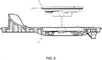
- Fig. 2
- eine schematische Ansicht eines Saugstutzens und eine schematische Schnittansicht einer Bodenplatte der Kreiselpumpe gemäß
Fig. 1 gemäß dem bevorzugten Ausführungsbeispiel der Erfindung, - Fig. 3
- eine perspektivische Ansicht des Saugstutzens und einen Ausschnitt der Bodenplatte gemäß
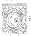
Fig. 2 gemäß dem bevorzugten Ausführungsbeispiel der Erfindung, - Fig. 4
- eine perspektivische, rückwärtige Teilansicht der Bodenplatte mit Saugstutzen im montierten Zustand gemäß
Fig. 3 gemäß dem bevorzugten Ausführungsbeispiel der Erfindung, und - Fig. 5
- eine perspektivische Ansicht des Saugstutzens und der Bodenplatte gemäß
Fig. 2 im montierten Zustand gemäß dem bevorzugten Ausführungsbeispiel der Erfindung. -
Fig. 1 zeigt eine schematische Schnittansicht einer Kreiselpumpe zur Verwendung als Schmutzwasser- und/oder Abwasser-Tauchpumpe gemäß einem bevorzugten Ausführungsbeispiel der Erfindung. Die Kreiselpumpe weist ein Pumpengehäuse 1 auf. Innerhalb des Pumpengehäuses ist ein Laufrad 2 und ein eine Saugöffnung ausbildender auf einer Bodenplatte 3 gehäuseinnenseitig abgestützter Saugstutzen 4 angeordnet. Das Laufrad 2 ist als halboffenes Mehrkanallaufrad ausgeführt ist und weist eine Mehrzahl nicht weiter gezeigte Laufradschaufeln 2 auf, die dem Saugstutzen 4 zugewandt sind. - Die Kreiselpumpe wird durch einen Tauchmotor angetrieben, wobei an einem Motorflansch das Pumpengehäuse 1 angebracht ist. Pumpengehäuse 1, Laufrad 2, Bodenplatte 3 und Saugstutzen 4 sind aus Glasfaser-verstärktem Kunststoff, insbesondere aus Glasfaser-verstärktem Polypropylen, hergestellt. Ein in das Laufrad 2 eingespritztes Metallinsert dient zur Verbindung mit der Motorwelle. Das Laufrad 2 ist durch eine Kegelverbindung kraftschlüssig mit der Motorwelle verbunden. Die Bodenplatte 3 ist von unten an das Pumpengehäuse 1 geschraubt, wie aus
Fig. 1 erkennbar, wobei zwischen Pumpengehäuse 1 und Bodenplatte 3 eine umlaufende Profildichtung 9 aus Nitrilkautschuk vorgesehen ist. Der Saugstutzen 4 ist in der Bodenplatte 3 konzentrisch zur Achse der Motorwelle gelagert. Als Schutz vor Verschleiß ist auf der dem Laufrad 2 zugewandten Seite ein Saugstutzen-Metallinsert 10 in Form eines Metallblechs in den Saugstutzen 4 eingespritzt, wie ausFig. 5 zu erkennen ist. - Wie im Detail aus
Fig. 2 und3 zu erkennen ist, die eine schematische Schnittansicht sowie eine perspektivische Ansicht des Saugstutzens 4, oben dargestellt, und der Bodenplatte 3, unten dargestellt, der Kreiselpumpe gemäßFig. 1 zeigen, weist die Bodenplatte 3 eine kreisrunde Zylinderfläche 5 auf, in die der Saugstutzen 4 mit seiner Unterseite einsetzbar ist. An der Unterseite des in Draufsicht kreisrunden Saugstutzens 4 sind drei rotationssymmetrisch hintereinander in einer 120° Teilung und konzentrisch um die Saugöffnung umlaufende Flächen 6 ausgebildet, die jeweils dieselbe Steigung haben und, im eingesetzten bzw. montierten Zustand, gegenüber der Bodenplatte 3 sowie einer Oberseite des Saugstutzens 4 verschwenkt sind. Die durch die Flächen 6 des Saugstutzens 4 gebildete Mittelachse entspricht der Mittelachse der Saugöffnung des Saugstutzens 4. - Korrespondierend dazu sind an einer Unterseite der Zylinderfläche 5 der Bodenplatte 3 ebenso drei rotationssymmetrisch hintereinander und um die Saugöffnung umlaufende Flächen 6 ausgebildet, so dass durch Einsetzen des Saugstutzens 4 in die Bodenplatte 3 die jeweiligen Flächen 6 der Bodenplatte 3 und des Saugstutzens 4 berührend aneinander anliegen und einen flächigen Kontakt ausbilden. Die durch die Flächen 6 der Bodenplatte 3 gebildete Mittelachse verläuft senkrecht zur Längsachs der Bodenplatte 3. Die Flächen 6 können, im Falle der Bodenplatte 3 wie ersichtlich aus
Fig. 3 , als durchgehende Flächen 6 ausbildet sein, wobei die Flächen 6 der Bodenplatte 6 durch nachfolgend beschriebene Langlöcher 7 unterbrochen sind, oder im Falle des Saugstutzens 4 durch eine rippenartige Struktur ausgebildet sein, um derart gemeinsam eine Art Wendeflächen oder Schraubflächen auszubilden. - Jedenfalls bewirken die jeweils gegenüber der Bodenplatte 3 verschwenkten und im montierten Zustand aneinander anliegenden Fläche 6 der Bodenplatte 3 sowie des Saugstutzens 4, dass durch Verdrehen des Saugstutzens 4 um eine durch die Saugöffnung definierte Achse ein Abstand zwischen dem Laufrad 2 und dem Saugstutzen 4 veränderbar ist. Konkret ist durch Verdrehen des Saugstutzens 4 der Abstand zwischen Kanten der Laufradschaufeln und der Planfläche des eingespritzten Saugstutzen-Metallinserts 10 variierbar, da die Flächen 6 aufeinander gleiten, so dass mit der Rotationsbewegung auch eine Translation des Saugstutzens 4 in Achsrichtung einhergeht.
- Um nach einem Verdrehen den Saugstutzen 4 an der Bodenplatte 3 zu fixieren, sind drei Befestigungsmittel 8 in Form von Schrauben vorgesehen, die durch drei an der Bodenplatte 3 vorgesehene bogenförmig ausgestaltete Langlöcher 7 geführt sind, wie in
Fig. 4 zu erkennen ist. Die Befestigungsmittel 8 tauchen jeweils von unten durch das Langloch 7 in der Bodenplatte 3. Ein Gewindefurchende Schraube als Befestigungsmittels 8 greift dabei im Saugstutzen 4, wobei eine Kopfauflage auf der Unterseite der Bodenplatte 3 geschieht, so dass der Saugstutzen 4 und die Bodenplatte 3 geklemmt und dadurch reibschlüssig verbunden sind. - Im Betrieb der Kreiselpumpe können sich zwischen Laufradkante und Saugstutzen 4 Feststoffe festsetzen, was dazu führt, dass durch Reibung ein Teil des Drehmomentes auf den Saugstutzen 4 übertragen wird. Um zu verhindern, dass sich durch das auf den Saugstutzen 4 übertragene Drehmoment die Fixierung zwischen Saugstutzen 4 und Bodenplatte 3 löst, ist die Drehrichtung des Laufrads 2 so gewählt, dass sich bei Rotation des Saugstutzens 4 in Drehrichtung des Laufrads 2 der Saugstutzen 4 axial in Richtung Laufrad 2 bewegt. Sofern der Saugstutzen 4 wie zuvor beschrieben durch dabei durch als Schrauben ausgeführte Befestigungsmittel 8 geklemmt ist, erhöht sich durch das Drehmoment lediglich die Klemmkraft der Befestigungsmittel 8, da die Flächen 6 auf Block gehen, so dass ein Lösen des Befestigungsmittels 8 verhindert wird.
- An einer Innenkante jedes Langlochs 7 ist eine Skala 11 eingebracht. Die Teilung ist so gewählt, dass eine Drehung von einem Teilstrich zum nächsten eine Axialbewegung des Saugstutzens von 0,1 mm zur Folge hat. Der maximal mögliche axiale Verstellweg ist durch die Steigung der Flächen 6 so gewählt, dass eine maximale Streubreite einer Toleranzkette des Laufradsitzes ausgeglichen werden kann, wobei sich vorliegend ein dafür benötigter Verstellweg von 3 mm ergibt. Ebenso kann die Skala eine feinere oder gröbere Abstufung aufweisen.
- . Damit sich der Saugstutzen 4 möglichst reibungsarm in der Bodenplatte 3 drehen kann, ist zwischen den radialen Kontaktflächen 6 beider Bauteile 3, 4 ein Spalt notwendig. Durch diesen Spalt kann jedoch ein Verlustvolumenstrom aus dem Hydraulikraum der Kreiselpumpe in die Umgebung entweichen. Zudem kann sich ein interner Verlustvolumenstrom im Hydraulikraum zwischen Hoch- und Niederdruckbereich einstellen. Um diese Verlustvolumenströme zu begrenzen, ist einerseits an dem Saugstutzen 4 zwischen der Fläche 6 und einer radialen Umfangsfläche 12 des Saugstutzens 4 eine kreisrund umlaufende V-Ring-Dichtung 13 vorgesehen, welche auf der Bodenplatte 3 aufliegt. Die V-Ring-Dichtung 13 ist dargestellt in
Fig. 1 , einerseits links innerhalb der Kreiselpumpe sowie andererseits als ausschnittsweise umrandete Vergrößerung rechts. Die V-Ring-Dichtung 13 ist über einen nach unten abgesetzten Durchmesser des Saugstutzens 4 gespannt. Die Dichtkante der V-Ring-Dichtung 13 liegt an einer ringförmigen Planfläche der Bodenplatte 3 an. Durch die Federwirkung der V-Ring-Dichtung 13 wird die axiale Bewegung beim Verdrehen des Saugstutzens 4 ausgeglichen, so dass die Dichtwirkung in jeder Position des Saugstutzens 4 gewährleistet ist. - Ferner ist an der radialen Umfangsfläche 12 des Saugstutzens 4 ein im montierten Zustand an der Zylinderfläche 5 der Bodenplatte 3 anliegender Dichtungsbund 14 vorgesehen. In einem nicht-montierten Zustand weist der Dichtungsbund 14 gegenüber der Zylinderfläche 5 der Bodenplatte 3 ein Übermaß auf, also einen größeren Durchmesser als der Innendurchmesser der Zylinderfläche 5. Durch diese zweistufige Abdichtung mit einem plastisch verformbaren Quetschrand als Dichtungsbund 14 in Kombination mit einer flexiblen V-Ring-Dichtung 13 ist eine ausreichende Dichtigkeit zwischen Bodenplatte 3 und Saustutzen 4 gegeben.
- Das beschriebene Ausführungsbeispiel ist lediglich ein Beispiel, das im Rahmen der Ansprüche auf vielfältige Weise modifiziert und/oder ergänzt werden können. Jedes Merkmal, das für ein bestimmtes Ausführungsbeispiel beschrieben wurde, kann eigenständig oder in Kombination mit anderen Merkmalen in einem beliebigen anderen Ausführungsbeispiel genutzt werden. Jedes Merkmal, dass für ein Ausführungsbeispiel einer bestimmten Kategorie beschrieben wurde, kann auch in entsprechender Weise in einem Ausführungsbeispiel einer anderen Kategorie eingesetzt werden.
Bezugszeichenliste Pumpengehäuse 1 Laufrad 2 Bodenplatte 3 Saugstutzen 4 Zylinderfläche 5 Fläche 6 Langloch 7 Befestigungsmittel 8 Profildichtung 9 Saugstutzen-Metallinsert 10 Skala 11 Umfangsfläche 12 Dichtung 13 Dichtungsbund 14
Claims (14)
- Kreiselpumpe mit einem Pumpengehäuse (1), wobeiin dem Pumpengehäuse (1) ein Laufrad (2) und ein eine Saugöffnung ausbildender und in eine Bodenplatte (3) des Pumpengehäuses einsetzbarer Saugstutzen (4) angeordnet sind,der Saugstutzen (4) auf der Bodenplatte (3) des Pumpengehäuses dadurch axial verschiebbar gelagert ist, dass der Saugstutzen (4) und die Bodenplatte (3) jeweils wenigstens eine gegenüber der Bodenplatte (3) verschwenkte und aneinander anliegende Fläche (6) aufweisen, so dass durch Verdrehen des Saugstutzens (4) ein Abstand zwischen dem Laufrad (2) und dem Saugstutzen (4) veränderbar ist, undder Saugstutzen (4) einen an einer radialen Umfangsfläche (12) des Saugstutzens (4) vorgesehenen und im eingesetzten Zustand an der Bodenplatte (3) anliegenden Dichtungsbund (14) aufweist, wobeider Dichtungsbund (14) als umlaufender, dünnwandiger Bund ausgeführt, der Dichtungsbund (14) an den Saugstutzen (4) angespritzt und/oder der Dichtungsbund (14) mit dem Saugstutzen (4) einteilig ausgeführt ist, und/oderdie Flächen (6) derart verschwenkt sind, dass durch Verdrehen des Saugstutzens (4) in Drehrichtung des Laufrads (2) der Abstand verringert wird.
- Kreiselpumpe nach dem vorhergehenden Anspruch, wobei die Flächen (6) als Wendelflächen oder als Schraubflächen ausgeführt sind, der Saugstutzen (4) und die Bodenplatte (3) jeweils zwei, drei, vier oder mehr rotationssymmetrisch hintereinander angeordnete Flächen (6) aufweisen, die Flächen (6) dieselbe Steigung aufweisen und/oder die Flächen (6) korrespondierend zueinander ausgeführt sind.
- Kreiselpumpe nach einem der vorhergehenden Ansprüche, mit einem Befestigungsmittel (8), durch welches der Saugstutzen (4) an der Bodenplatte (3) fixierbar ist und/oder mit einem als Schraube ausgeführten Befestigungsmittel (8), welches durch ein an der Bodenplatte vorgesehenes bogenförmig ausgestaltetes Langloch (7) geführt ist.
- Kreiselpumpe nach einem der vorhergehenden Ansprüche, wobei die Bodenplatte (3) eine Zylinderfläche (5) aufweist, an der der Dichtungsbund (14) insbesondere umlaufend und/oder berührend anliegt.
- Kreiselpumpe nach einem der vorhergehenden Ansprüche, wobei an dem Saugstutzen (4) zwischen der Fläche (6) und der Umfangsfläche (12) eine Dichtung (13), insbesondere eine umlaufende und/oder V-Ring-Dichtung (13), vorgesehen ist, welche auf der Bodenplatte (3) aufliegt.
- Kreiselpumpe nach einem der vorhergehenden Ansprüche, wobei der Dichtungsbund (14) gegenüber einer Zylinderfläche (5) der Bodenplatte (3), an der der Dichtungsbund (14) in einem montierten Zustand anliegt, in einem nicht-montierten Zustand ein Übermaß aufweist.
- Kreiselpumpe nach einem der vorhergehenden Ansprüche, mit einem Antriebsmotor und wobei das Laufrad (2) ein insbesondere eingespritztes Metallinsert aufweist, welche in Wirkverbindung mit einer Motorwelle des Antriebsmotors steht.
- Kreiselpumpe nach einem der vorhergehenden Ansprüche, wobei auf der dem Laufrad (2) zugewandten Seite des Saugstutzens (4) ein insbesondere eingespritztes Saugstutzen-Metallinsert (10) vorgesehen ist.
- Kreiselpumpe nach dem vorhergehenden Anspruch, wobei das Laufrad (2) mittels einer Kegelverbindung kraftschlüssig mit der Motorwelle verbunden ist.
- Kreiselpumpe nach einem der beiden vorhergehenden Ansprüchen, wobei der Saugstutzen (4) in der Bodenplatte (3) konzentrisch zur Achse der Motorwelle gelagert ist.
- Kreiselpumpe nach einem der vorhergehenden Ansprüche, wobei die Bodenplatte (3) an das Pumpengehäuse (1) anschraubbar ist, wobei das Laufrad (2) als halboffenes Mehrkanallaufrad ausgeführt ist, wobei das Laufrad (2) wenigstens eine Laufradschaufel aufweist und durch Verdrehen des Saugstutzens (4) der Abstand zwischen der wenigstens einen Laufradschaufel und dem Saugstutzen (4) veränderbar ist, und/oder wobei zwischen Pumpengehäuse (1) und Bodenplatte (3) eine umlaufende Profildichtung (9), insbesondere aus Nitrilkautschuk, vorgesehen ist.
- Kreiselpumpe nach einem der vorhergehenden Ansprüche, wobei die Bodenplatte (3) und/oder der Saugstutzen (4) Glasfaser-verstärkten Kunststoff, insbesondere Glasfaserverstärktes Polypropylen aufweist.
- Verwendung einer Kreiselpumpe nach einem der vorhergehenden Ansprüche als Schmutzwasser und/oder Abwasser-Tauchpumpe
- Verfahren zum Herstellen einer Kreiselpumpe mit einem Pumpengehäuse (1) und einem Laufrad (2), aufweisend die Schritte:Spritzgießen einer Bodenplatte (3) und eines in die Bodenplatte (3) einsetzbaren und auf dieser lagerbaren Saugstutzens (4) derart, dass der Saugstutzen (4) und die Bodenplatte (3) jeweils wenigstens eine gegenüber der Bodenplatte (3) verschwenkte und im montierten Zustand aneinander anliegende Fläche (6) aufweisen, so dass durch Verdrehen des Saugstutzens (4) ein Abstand zwischen dem Laufrad (2) und dem Saugstutzen (4) veränderbar ist, undSpritzgießen eines Dichtungsbunds (14) an eine radiale Umfangsfläche (12) des Saugstutzens (4) derart, dass der Dichtungsbund (14) im eingesetzten Zustand an der Bodenplatte (3) anliegt, wobeider Dichtungsbund (14) als umlaufender, dünnwandiger Bund ausgeführt, der Dichtungsbund (14) an den Saugstutzen (4) angespritzt und/oder der Dichtungsbund (14) mit dem Saugstutzen (4) einteilig ausgeführt ist, und/oderdie Flächen (6) derart verschwenkt sind, dass durch Verdrehen des Saugstutzens (4) in Drehrichtung des Laufrads (2) der Abstand verringert wird.
Priority Applications (2)
| Application Number | Priority Date | Filing Date | Title |
|---|---|---|---|
| PL19178039T PL3581803T3 (pl) | 2018-06-12 | 2019-06-04 | Wirnikowa pompa z regulacją szczeliny pomiędzy pokrywą i wirnikiem |
| EP21208695.3A EP4001665B1 (de) | 2018-06-12 | 2019-06-04 | Kreiselpumpe mit einem pumpengehäuse |
Applications Claiming Priority (1)
| Application Number | Priority Date | Filing Date | Title |
|---|---|---|---|
| LU100831A LU100831B1 (de) | 2018-06-12 | 2018-06-12 | Kreiselpumpe mit einem Pumpengehäuse |
Related Child Applications (2)
| Application Number | Title | Priority Date | Filing Date |
|---|---|---|---|
| EP21208695.3A Division EP4001665B1 (de) | 2018-06-12 | 2019-06-04 | Kreiselpumpe mit einem pumpengehäuse |
| EP21208695.3A Division-Into EP4001665B1 (de) | 2018-06-12 | 2019-06-04 | Kreiselpumpe mit einem pumpengehäuse |
Publications (2)
| Publication Number | Publication Date |
|---|---|
| EP3581803A1 true EP3581803A1 (de) | 2019-12-18 |
| EP3581803B1 EP3581803B1 (de) | 2022-03-02 |
Family
ID=63113593
Family Applications (2)
| Application Number | Title | Priority Date | Filing Date |
|---|---|---|---|
| EP21208695.3A Active EP4001665B1 (de) | 2018-06-12 | 2019-06-04 | Kreiselpumpe mit einem pumpengehäuse |
| EP19178039.4A Active EP3581803B1 (de) | 2018-06-12 | 2019-06-04 | Kreiselpumpe mit regelung des spaltes zwischen deckel und laufrad |
Family Applications Before (1)
| Application Number | Title | Priority Date | Filing Date |
|---|---|---|---|
| EP21208695.3A Active EP4001665B1 (de) | 2018-06-12 | 2019-06-04 | Kreiselpumpe mit einem pumpengehäuse |
Country Status (5)
| Country | Link |
|---|---|
| EP (2) | EP4001665B1 (de) |
| HU (2) | HUE063402T2 (de) |
| LU (1) | LU100831B1 (de) |
| PL (2) | PL4001665T3 (de) |
| RU (1) | RU2707238C1 (de) |
Cited By (1)
| Publication number | Priority date | Publication date | Assignee | Title |
|---|---|---|---|---|
| US12297837B2 (en) | 2021-09-09 | 2025-05-13 | Techtronic Cordless Gp | Submersible pump |
Families Citing this family (1)
| Publication number | Priority date | Publication date | Assignee | Title |
|---|---|---|---|---|
| LU500240B1 (de) * | 2021-06-02 | 2022-12-02 | Wilo Se | Abwasserkreiselpumpe zur Tiefabsaugung gesammelten Abwassers |
Citations (3)
| Publication number | Priority date | Publication date | Assignee | Title |
|---|---|---|---|---|
| DE117218C (de) * | 1900-02-14 | 1901-02-01 | ||
| FR2290133A6 (fr) * | 1973-02-09 | 1976-05-28 | Materiel Processing Internal | Pompe centrifuge |
| WO2017160624A1 (en) * | 2016-03-18 | 2017-09-21 | Weir Slurry Group, Inc. | Sealing arrangement for adjustable elements of a pump |
Family Cites Families (5)
| Publication number | Priority date | Publication date | Assignee | Title |
|---|---|---|---|---|
| US3499388A (en) * | 1967-06-13 | 1970-03-10 | Hale Fire Pump Co | Centrifugal pump |
| FR2681906B1 (fr) * | 1991-09-27 | 1995-01-20 | Renault Vehicules Ind | Pompe centrifuge pour circuit de liquide de refroidissement de moteur a combustion. |
| EP1906025A1 (de) * | 2006-09-22 | 2008-04-02 | Frideco AG | Zentrifugalradpumpe |
| RU80519U1 (ru) * | 2008-06-04 | 2009-02-10 | Григорий Иванович Егоров | Регулируемый центробежный насос |
| DE102012023734A1 (de) * | 2012-12-05 | 2014-06-05 | Wilo Se | Kreiselpumpe insbesondere für Abwasser oder Schmutzwasser |
-
2018
- 2018-06-12 LU LU100831A patent/LU100831B1/de active IP Right Grant
-
2019
- 2019-05-29 RU RU2019116662A patent/RU2707238C1/ru active
- 2019-06-04 EP EP21208695.3A patent/EP4001665B1/de active Active
- 2019-06-04 EP EP19178039.4A patent/EP3581803B1/de active Active
- 2019-06-04 PL PL21208695.3T patent/PL4001665T3/pl unknown
- 2019-06-04 HU HUE21208695A patent/HUE063402T2/hu unknown
- 2019-06-04 HU HUE19178039A patent/HUE058654T2/hu unknown
- 2019-06-04 PL PL19178039T patent/PL3581803T3/pl unknown
Patent Citations (3)
| Publication number | Priority date | Publication date | Assignee | Title |
|---|---|---|---|---|
| DE117218C (de) * | 1900-02-14 | 1901-02-01 | ||
| FR2290133A6 (fr) * | 1973-02-09 | 1976-05-28 | Materiel Processing Internal | Pompe centrifuge |
| WO2017160624A1 (en) * | 2016-03-18 | 2017-09-21 | Weir Slurry Group, Inc. | Sealing arrangement for adjustable elements of a pump |
Cited By (1)
| Publication number | Priority date | Publication date | Assignee | Title |
|---|---|---|---|---|
| US12297837B2 (en) | 2021-09-09 | 2025-05-13 | Techtronic Cordless Gp | Submersible pump |
Also Published As
| Publication number | Publication date |
|---|---|
| PL3581803T3 (pl) | 2022-05-02 |
| RU2707238C1 (ru) | 2019-11-25 |
| EP4001665A1 (de) | 2022-05-25 |
| PL4001665T3 (pl) | 2023-10-30 |
| HUE058654T2 (hu) | 2022-09-28 |
| EP4001665B1 (de) | 2023-08-23 |
| LU100831B1 (de) | 2019-12-12 |
| EP3581803B1 (de) | 2022-03-02 |
| HUE063402T2 (hu) | 2024-01-28 |
Similar Documents
| Publication | Publication Date | Title |
|---|---|---|
| EP1267107B1 (de) | Stangen- und Kolbenprimärdichtung | |
| DE69111691T2 (de) | Geteilte Gleitringdichtung. | |
| DE69628549T2 (de) | Zentrifugalpumpe | |
| DE3926852A1 (de) | Staudruckfluid-lagereinrichtung | |
| WO2009138082A1 (de) | Vorrichtung zur laufradabdichtung bei kreiselpumpen | |
| DE69901673T2 (de) | Befestigungsmittel | |
| EP3441619B1 (de) | Kreiselpumpe | |
| EP2740940A1 (de) | Tauchpumpe | |
| EP3581803B1 (de) | Kreiselpumpe mit regelung des spaltes zwischen deckel und laufrad | |
| DE102009056231A1 (de) | Schneckenverdichter (Scroll-Verdichter) | |
| DE2653505A1 (de) | Lagerhalteplatte fuer ein buchsendrehlager | |
| EP3029334A1 (de) | Axial geteilte pumpe | |
| DE1273937B (de) | Gleitringdichtung | |
| DE2544536A1 (de) | Halterung fuer die den hydraulischen kreislauf einer fertigungsmaschine antreibende pumpe | |
| DE69017216T2 (de) | Drehbares wechselventil mit flachen absperrschiebern. | |
| WO2005066496A1 (de) | Drehkolbenpumpe mit axial beweglichem flügel | |
| EP3467319B1 (de) | Kreiselpumpe mit verbesserter saughalsdichtung | |
| DE202005001604U1 (de) | Seitenkanalverdichter | |
| EP3171033A1 (de) | Mehrstufige kreiselpumpe mit gehäuseöffnung zur wartung eines axialschub-kolbens | |
| DE102014101767B4 (de) | Flussregler | |
| EP2818722B1 (de) | Kreiselpumpe | |
| EP3853480B1 (de) | Pumpenanordnung | |
| EP2618033B1 (de) | Membranventil | |
| DE102017105776A1 (de) | Hydraulische Drehdurchführung | |
| EP1336780B1 (de) | Sekundärdichtungselement für eine Gleitringdichtungsanordnung |
Legal Events
| Date | Code | Title | Description |
|---|---|---|---|
| PUAI | Public reference made under article 153(3) epc to a published international application that has entered the european phase |
Free format text: ORIGINAL CODE: 0009012 |
|
| STAA | Information on the status of an ep patent application or granted ep patent |
Free format text: STATUS: THE APPLICATION HAS BEEN PUBLISHED |
|
| AK | Designated contracting states |
Kind code of ref document: A1 Designated state(s): AL AT BE BG CH CY CZ DE DK EE ES FI FR GB GR HR HU IE IS IT LI LT LU LV MC MK MT NL NO PL PT RO RS SE SI SK SM TR |
|
| STAA | Information on the status of an ep patent application or granted ep patent |
Free format text: STATUS: REQUEST FOR EXAMINATION WAS MADE |
|
| 17P | Request for examination filed |
Effective date: 20200113 |
|
| RBV | Designated contracting states (corrected) |
Designated state(s): AL AT BE BG CH CY CZ DE DK EE ES FI FR GB GR HR HU IE IS IT LI LT LU LV MC MK MT NL NO PL PT RO RS SE SI SK SM TR |
|
| GRAP | Despatch of communication of intention to grant a patent |
Free format text: ORIGINAL CODE: EPIDOSNIGR1 |
|
| STAA | Information on the status of an ep patent application or granted ep patent |
Free format text: STATUS: GRANT OF PATENT IS INTENDED |
|
| INTG | Intention to grant announced |
Effective date: 20211022 |
|
| GRAS | Grant fee paid |
Free format text: ORIGINAL CODE: EPIDOSNIGR3 |
|
| GRAA | (expected) grant |
Free format text: ORIGINAL CODE: 0009210 |
|
| STAA | Information on the status of an ep patent application or granted ep patent |
Free format text: STATUS: THE PATENT HAS BEEN GRANTED |
|
| AK | Designated contracting states |
Kind code of ref document: B1 Designated state(s): AL AT BE BG CH CY CZ DE DK EE ES FI FR GB GR HR HU IE IS IT LI LT LU LV MC MK MT NL NO PL PT RO RS SE SI SK SM TR |
|
| REG | Reference to a national code |
Ref country code: GB Ref legal event code: FG4D Free format text: NOT ENGLISH |
|
| REG | Reference to a national code |
Ref country code: CH Ref legal event code: EP Ref country code: AT Ref legal event code: REF Ref document number: 1472466 Country of ref document: AT Kind code of ref document: T Effective date: 20220315 |
|
| REG | Reference to a national code |
Ref country code: DE Ref legal event code: R096 Ref document number: 502019003527 Country of ref document: DE |
|
| REG | Reference to a national code |
Ref country code: IE Ref legal event code: FG4D Free format text: LANGUAGE OF EP DOCUMENT: GERMAN |
|
| REG | Reference to a national code |
Ref country code: LT Ref legal event code: MG9D |
|
| REG | Reference to a national code |
Ref country code: NL Ref legal event code: MP Effective date: 20220302 |
|
| PG25 | Lapsed in a contracting state [announced via postgrant information from national office to epo] |
Ref country code: SE Free format text: LAPSE BECAUSE OF FAILURE TO SUBMIT A TRANSLATION OF THE DESCRIPTION OR TO PAY THE FEE WITHIN THE PRESCRIBED TIME-LIMIT Effective date: 20220302 Ref country code: RS Free format text: LAPSE BECAUSE OF FAILURE TO SUBMIT A TRANSLATION OF THE DESCRIPTION OR TO PAY THE FEE WITHIN THE PRESCRIBED TIME-LIMIT Effective date: 20220302 Ref country code: NO Free format text: LAPSE BECAUSE OF FAILURE TO SUBMIT A TRANSLATION OF THE DESCRIPTION OR TO PAY THE FEE WITHIN THE PRESCRIBED TIME-LIMIT Effective date: 20220602 Ref country code: LT Free format text: LAPSE BECAUSE OF FAILURE TO SUBMIT A TRANSLATION OF THE DESCRIPTION OR TO PAY THE FEE WITHIN THE PRESCRIBED TIME-LIMIT Effective date: 20220302 Ref country code: HR Free format text: LAPSE BECAUSE OF FAILURE TO SUBMIT A TRANSLATION OF THE DESCRIPTION OR TO PAY THE FEE WITHIN THE PRESCRIBED TIME-LIMIT Effective date: 20220302 Ref country code: ES Free format text: LAPSE BECAUSE OF FAILURE TO SUBMIT A TRANSLATION OF THE DESCRIPTION OR TO PAY THE FEE WITHIN THE PRESCRIBED TIME-LIMIT Effective date: 20220302 Ref country code: BG Free format text: LAPSE BECAUSE OF FAILURE TO SUBMIT A TRANSLATION OF THE DESCRIPTION OR TO PAY THE FEE WITHIN THE PRESCRIBED TIME-LIMIT Effective date: 20220602 |
|
| PG25 | Lapsed in a contracting state [announced via postgrant information from national office to epo] |
Ref country code: LV Free format text: LAPSE BECAUSE OF FAILURE TO SUBMIT A TRANSLATION OF THE DESCRIPTION OR TO PAY THE FEE WITHIN THE PRESCRIBED TIME-LIMIT Effective date: 20220302 Ref country code: GR Free format text: LAPSE BECAUSE OF FAILURE TO SUBMIT A TRANSLATION OF THE DESCRIPTION OR TO PAY THE FEE WITHIN THE PRESCRIBED TIME-LIMIT Effective date: 20220603 Ref country code: FI Free format text: LAPSE BECAUSE OF FAILURE TO SUBMIT A TRANSLATION OF THE DESCRIPTION OR TO PAY THE FEE WITHIN THE PRESCRIBED TIME-LIMIT Effective date: 20220302 |
|
| REG | Reference to a national code |
Ref country code: HU Ref legal event code: AG4A Ref document number: E058654 Country of ref document: HU |
|
| PG25 | Lapsed in a contracting state [announced via postgrant information from national office to epo] |
Ref country code: NL Free format text: LAPSE BECAUSE OF FAILURE TO SUBMIT A TRANSLATION OF THE DESCRIPTION OR TO PAY THE FEE WITHIN THE PRESCRIBED TIME-LIMIT Effective date: 20220302 |
|
| PG25 | Lapsed in a contracting state [announced via postgrant information from national office to epo] |
Ref country code: SM Free format text: LAPSE BECAUSE OF FAILURE TO SUBMIT A TRANSLATION OF THE DESCRIPTION OR TO PAY THE FEE WITHIN THE PRESCRIBED TIME-LIMIT Effective date: 20220302 Ref country code: SK Free format text: LAPSE BECAUSE OF FAILURE TO SUBMIT A TRANSLATION OF THE DESCRIPTION OR TO PAY THE FEE WITHIN THE PRESCRIBED TIME-LIMIT Effective date: 20220302 Ref country code: RO Free format text: LAPSE BECAUSE OF FAILURE TO SUBMIT A TRANSLATION OF THE DESCRIPTION OR TO PAY THE FEE WITHIN THE PRESCRIBED TIME-LIMIT Effective date: 20220302 Ref country code: PT Free format text: LAPSE BECAUSE OF FAILURE TO SUBMIT A TRANSLATION OF THE DESCRIPTION OR TO PAY THE FEE WITHIN THE PRESCRIBED TIME-LIMIT Effective date: 20220704 Ref country code: EE Free format text: LAPSE BECAUSE OF FAILURE TO SUBMIT A TRANSLATION OF THE DESCRIPTION OR TO PAY THE FEE WITHIN THE PRESCRIBED TIME-LIMIT Effective date: 20220302 Ref country code: CZ Free format text: LAPSE BECAUSE OF FAILURE TO SUBMIT A TRANSLATION OF THE DESCRIPTION OR TO PAY THE FEE WITHIN THE PRESCRIBED TIME-LIMIT Effective date: 20220302 |
|
| PG25 | Lapsed in a contracting state [announced via postgrant information from national office to epo] |
Ref country code: IS Free format text: LAPSE BECAUSE OF FAILURE TO SUBMIT A TRANSLATION OF THE DESCRIPTION OR TO PAY THE FEE WITHIN THE PRESCRIBED TIME-LIMIT Effective date: 20220702 Ref country code: AL Free format text: LAPSE BECAUSE OF FAILURE TO SUBMIT A TRANSLATION OF THE DESCRIPTION OR TO PAY THE FEE WITHIN THE PRESCRIBED TIME-LIMIT Effective date: 20220302 |
|
| REG | Reference to a national code |
Ref country code: DE Ref legal event code: R097 Ref document number: 502019003527 Country of ref document: DE |
|
| PLBE | No opposition filed within time limit |
Free format text: ORIGINAL CODE: 0009261 |
|
| STAA | Information on the status of an ep patent application or granted ep patent |
Free format text: STATUS: NO OPPOSITION FILED WITHIN TIME LIMIT |
|
| PG25 | Lapsed in a contracting state [announced via postgrant information from national office to epo] |
Ref country code: MC Free format text: LAPSE BECAUSE OF FAILURE TO SUBMIT A TRANSLATION OF THE DESCRIPTION OR TO PAY THE FEE WITHIN THE PRESCRIBED TIME-LIMIT Effective date: 20220302 Ref country code: DK Free format text: LAPSE BECAUSE OF FAILURE TO SUBMIT A TRANSLATION OF THE DESCRIPTION OR TO PAY THE FEE WITHIN THE PRESCRIBED TIME-LIMIT Effective date: 20220302 |
|
| REG | Reference to a national code |
Ref country code: CH Ref legal event code: PL |
|
| 26N | No opposition filed |
Effective date: 20221205 |
|
| REG | Reference to a national code |
Ref country code: BE Ref legal event code: MM Effective date: 20220630 |
|
| PG25 | Lapsed in a contracting state [announced via postgrant information from national office to epo] |
Ref country code: SI Free format text: LAPSE BECAUSE OF FAILURE TO SUBMIT A TRANSLATION OF THE DESCRIPTION OR TO PAY THE FEE WITHIN THE PRESCRIBED TIME-LIMIT Effective date: 20220302 |
|
| PG25 | Lapsed in a contracting state [announced via postgrant information from national office to epo] |
Ref country code: LU Free format text: LAPSE BECAUSE OF NON-PAYMENT OF DUE FEES Effective date: 20220604 Ref country code: LI Free format text: LAPSE BECAUSE OF NON-PAYMENT OF DUE FEES Effective date: 20220630 Ref country code: IE Free format text: LAPSE BECAUSE OF NON-PAYMENT OF DUE FEES Effective date: 20220604 Ref country code: CH Free format text: LAPSE BECAUSE OF NON-PAYMENT OF DUE FEES Effective date: 20220630 |
|
| PG25 | Lapsed in a contracting state [announced via postgrant information from national office to epo] |
Ref country code: BE Free format text: LAPSE BECAUSE OF NON-PAYMENT OF DUE FEES Effective date: 20220630 |
|
| P01 | Opt-out of the competence of the unified patent court (upc) registered |
Effective date: 20230615 |
|
| PG25 | Lapsed in a contracting state [announced via postgrant information from national office to epo] |
Ref country code: IT Free format text: LAPSE BECAUSE OF FAILURE TO SUBMIT A TRANSLATION OF THE DESCRIPTION OR TO PAY THE FEE WITHIN THE PRESCRIBED TIME-LIMIT Effective date: 20220302 |
|
| GBPC | Gb: european patent ceased through non-payment of renewal fee |
Effective date: 20230604 |
|
| PG25 | Lapsed in a contracting state [announced via postgrant information from national office to epo] |
Ref country code: MK Free format text: LAPSE BECAUSE OF FAILURE TO SUBMIT A TRANSLATION OF THE DESCRIPTION OR TO PAY THE FEE WITHIN THE PRESCRIBED TIME-LIMIT Effective date: 20220302 Ref country code: CY Free format text: LAPSE BECAUSE OF FAILURE TO SUBMIT A TRANSLATION OF THE DESCRIPTION OR TO PAY THE FEE WITHIN THE PRESCRIBED TIME-LIMIT Effective date: 20220302 Ref country code: GB Free format text: LAPSE BECAUSE OF NON-PAYMENT OF DUE FEES Effective date: 20230604 |
|
| PG25 | Lapsed in a contracting state [announced via postgrant information from national office to epo] |
Ref country code: MT Free format text: LAPSE BECAUSE OF FAILURE TO SUBMIT A TRANSLATION OF THE DESCRIPTION OR TO PAY THE FEE WITHIN THE PRESCRIBED TIME-LIMIT Effective date: 20220302 |
|
| PGFP | Annual fee paid to national office [announced via postgrant information from national office to epo] |
Ref country code: PL Payment date: 20250522 Year of fee payment: 7 Ref country code: DE Payment date: 20250520 Year of fee payment: 7 |
|
| PGFP | Annual fee paid to national office [announced via postgrant information from national office to epo] |
Ref country code: HU Payment date: 20250613 Year of fee payment: 7 Ref country code: FR Payment date: 20250520 Year of fee payment: 7 |
|
| PGFP | Annual fee paid to national office [announced via postgrant information from national office to epo] |
Ref country code: AT Payment date: 20250522 Year of fee payment: 7 |
|
| PG25 | Lapsed in a contracting state [announced via postgrant information from national office to epo] |
Ref country code: TR Free format text: LAPSE BECAUSE OF FAILURE TO SUBMIT A TRANSLATION OF THE DESCRIPTION OR TO PAY THE FEE WITHIN THE PRESCRIBED TIME-LIMIT Effective date: 20220302 |