EP3029334A1 - Axial geteilte pumpe - Google Patents
Axial geteilte pumpe Download PDFInfo
- Publication number
- EP3029334A1 EP3029334A1 EP15189338.5A EP15189338A EP3029334A1 EP 3029334 A1 EP3029334 A1 EP 3029334A1 EP 15189338 A EP15189338 A EP 15189338A EP 3029334 A1 EP3029334 A1 EP 3029334A1
- Authority
- EP
- European Patent Office
- Prior art keywords
- sealing
- cord
- pump
- pump according
- shaped sealing
- Prior art date
- Legal status (The legal status is an assumption and is not a legal conclusion. Google has not performed a legal analysis and makes no representation as to the accuracy of the status listed.)
- Granted
Links
- 238000007789 sealing Methods 0.000 claims abstract description 193
- 239000012530 fluid Substances 0.000 claims abstract description 11
- 229920000459 Nitrile rubber Polymers 0.000 claims description 13
- 229920001971 elastomer Polymers 0.000 claims description 4
- 239000000806 elastomer Substances 0.000 claims description 4
- 239000004033 plastic Substances 0.000 claims description 3
- 230000000694 effects Effects 0.000 description 6
- 239000000463 material Substances 0.000 description 4
- 238000004519 manufacturing process Methods 0.000 description 3
- 230000004323 axial length Effects 0.000 description 2
- 230000015556 catabolic process Effects 0.000 description 2
- 238000006731 degradation reaction Methods 0.000 description 2
- 238000002347 injection Methods 0.000 description 2
- 239000007924 injection Substances 0.000 description 2
- 238000005086 pumping Methods 0.000 description 2
- 239000000243 solution Substances 0.000 description 2
- XLYOFNOQVPJJNP-UHFFFAOYSA-N water Substances O XLYOFNOQVPJJNP-UHFFFAOYSA-N 0.000 description 2
- 230000002411 adverse Effects 0.000 description 1
- 230000015572 biosynthetic process Effects 0.000 description 1
- 230000008878 coupling Effects 0.000 description 1
- 238000010168 coupling process Methods 0.000 description 1
- 238000005859 coupling reaction Methods 0.000 description 1
- 230000003247 decreasing effect Effects 0.000 description 1
- 230000001419 dependent effect Effects 0.000 description 1
- 238000010612 desalination reaction Methods 0.000 description 1
- 238000005516 engineering process Methods 0.000 description 1
- 210000004907 gland Anatomy 0.000 description 1
- 238000003780 insertion Methods 0.000 description 1
- 230000037431 insertion Effects 0.000 description 1
- 230000003993 interaction Effects 0.000 description 1
- CNQCVBJFEGMYDW-UHFFFAOYSA-N lawrencium atom Chemical compound [Lr] CNQCVBJFEGMYDW-UHFFFAOYSA-N 0.000 description 1
- 230000007774 longterm Effects 0.000 description 1
- 238000012423 maintenance Methods 0.000 description 1
- 230000001404 mediated effect Effects 0.000 description 1
- 230000002035 prolonged effect Effects 0.000 description 1
- 238000001223 reverse osmosis Methods 0.000 description 1
- 239000013535 sea water Substances 0.000 description 1
- 230000035939 shock Effects 0.000 description 1
Images


Classifications
-
- F—MECHANICAL ENGINEERING; LIGHTING; HEATING; WEAPONS; BLASTING
- F04—POSITIVE - DISPLACEMENT MACHINES FOR LIQUIDS; PUMPS FOR LIQUIDS OR ELASTIC FLUIDS
- F04D—NON-POSITIVE-DISPLACEMENT PUMPS
- F04D29/00—Details, component parts, or accessories
- F04D29/08—Sealings
- F04D29/086—Sealings especially adapted for liquid pumps
-
- F—MECHANICAL ENGINEERING; LIGHTING; HEATING; WEAPONS; BLASTING
- F04—POSITIVE - DISPLACEMENT MACHINES FOR LIQUIDS; PUMPS FOR LIQUIDS OR ELASTIC FLUIDS
- F04D—NON-POSITIVE-DISPLACEMENT PUMPS
- F04D1/00—Radial-flow pumps, e.g. centrifugal pumps; Helico-centrifugal pumps
- F04D1/06—Multi-stage pumps
-
- F—MECHANICAL ENGINEERING; LIGHTING; HEATING; WEAPONS; BLASTING
- F04—POSITIVE - DISPLACEMENT MACHINES FOR LIQUIDS; PUMPS FOR LIQUIDS OR ELASTIC FLUIDS
- F04D—NON-POSITIVE-DISPLACEMENT PUMPS
- F04D17/00—Radial-flow pumps, e.g. centrifugal pumps; Helico-centrifugal pumps
- F04D17/08—Centrifugal pumps
-
- F—MECHANICAL ENGINEERING; LIGHTING; HEATING; WEAPONS; BLASTING
- F04—POSITIVE - DISPLACEMENT MACHINES FOR LIQUIDS; PUMPS FOR LIQUIDS OR ELASTIC FLUIDS
- F04D—NON-POSITIVE-DISPLACEMENT PUMPS
- F04D29/00—Details, component parts, or accessories
- F04D29/08—Sealings
- F04D29/083—Sealings especially adapted for elastic fluid pumps
-
- F—MECHANICAL ENGINEERING; LIGHTING; HEATING; WEAPONS; BLASTING
- F04—POSITIVE - DISPLACEMENT MACHINES FOR LIQUIDS; PUMPS FOR LIQUIDS OR ELASTIC FLUIDS
- F04D—NON-POSITIVE-DISPLACEMENT PUMPS
- F04D29/00—Details, component parts, or accessories
- F04D29/18—Rotors
- F04D29/22—Rotors specially for centrifugal pumps
-
- F—MECHANICAL ENGINEERING; LIGHTING; HEATING; WEAPONS; BLASTING
- F04—POSITIVE - DISPLACEMENT MACHINES FOR LIQUIDS; PUMPS FOR LIQUIDS OR ELASTIC FLUIDS
- F04D—NON-POSITIVE-DISPLACEMENT PUMPS
- F04D29/00—Details, component parts, or accessories
- F04D29/26—Rotors specially for elastic fluids
- F04D29/28—Rotors specially for elastic fluids for centrifugal or helico-centrifugal pumps for radial-flow or helico-centrifugal pumps
-
- F—MECHANICAL ENGINEERING; LIGHTING; HEATING; WEAPONS; BLASTING
- F04—POSITIVE - DISPLACEMENT MACHINES FOR LIQUIDS; PUMPS FOR LIQUIDS OR ELASTIC FLUIDS
- F04D—NON-POSITIVE-DISPLACEMENT PUMPS
- F04D29/00—Details, component parts, or accessories
- F04D29/40—Casings; Connections of working fluid
- F04D29/42—Casings; Connections of working fluid for radial or helico-centrifugal pumps
- F04D29/4206—Casings; Connections of working fluid for radial or helico-centrifugal pumps especially adapted for elastic fluid pumps
-
- F—MECHANICAL ENGINEERING; LIGHTING; HEATING; WEAPONS; BLASTING
- F04—POSITIVE - DISPLACEMENT MACHINES FOR LIQUIDS; PUMPS FOR LIQUIDS OR ELASTIC FLUIDS
- F04D—NON-POSITIVE-DISPLACEMENT PUMPS
- F04D29/00—Details, component parts, or accessories
- F04D29/40—Casings; Connections of working fluid
- F04D29/42—Casings; Connections of working fluid for radial or helico-centrifugal pumps
- F04D29/426—Casings; Connections of working fluid for radial or helico-centrifugal pumps especially adapted for liquid pumps
-
- F—MECHANICAL ENGINEERING; LIGHTING; HEATING; WEAPONS; BLASTING
- F04—POSITIVE - DISPLACEMENT MACHINES FOR LIQUIDS; PUMPS FOR LIQUIDS OR ELASTIC FLUIDS
- F04D—NON-POSITIVE-DISPLACEMENT PUMPS
- F04D29/00—Details, component parts, or accessories
- F04D29/60—Mounting; Assembling; Disassembling
- F04D29/62—Mounting; Assembling; Disassembling of radial or helico-centrifugal pumps
- F04D29/624—Mounting; Assembling; Disassembling of radial or helico-centrifugal pumps especially adapted for elastic fluid pumps
-
- F—MECHANICAL ENGINEERING; LIGHTING; HEATING; WEAPONS; BLASTING
- F04—POSITIVE - DISPLACEMENT MACHINES FOR LIQUIDS; PUMPS FOR LIQUIDS OR ELASTIC FLUIDS
- F04D—NON-POSITIVE-DISPLACEMENT PUMPS
- F04D29/00—Details, component parts, or accessories
- F04D29/60—Mounting; Assembling; Disassembling
- F04D29/62—Mounting; Assembling; Disassembling of radial or helico-centrifugal pumps
- F04D29/628—Mounting; Assembling; Disassembling of radial or helico-centrifugal pumps especially adapted for liquid pumps
-
- F—MECHANICAL ENGINEERING; LIGHTING; HEATING; WEAPONS; BLASTING
- F16—ENGINEERING ELEMENTS AND UNITS; GENERAL MEASURES FOR PRODUCING AND MAINTAINING EFFECTIVE FUNCTIONING OF MACHINES OR INSTALLATIONS; THERMAL INSULATION IN GENERAL
- F16J—PISTONS; CYLINDERS; SEALINGS
- F16J15/00—Sealings
- F16J15/02—Sealings between relatively-stationary surfaces
- F16J15/06—Sealings between relatively-stationary surfaces with solid packing compressed between sealing surfaces
- F16J15/062—Sealings between relatively-stationary surfaces with solid packing compressed between sealing surfaces characterised by the geometry of the seat
Definitions
- the invention relates to an axially divided pump for conveying a fluid according to the preamble of the independent claim.
- Axially split pumps also referred to as horizontally split pumps, are pumps in which the housing is split parallel to the axis of the shaft and thus has a base and cover. Both the lower part and the lid each have a flange, which are stacked for mounting the pump and then firmly connected to each other, for example, screwed.
- Axially split pumps have long been well known and in many embodiments are usually manufactured as centrifugal pumps, for example as single or double-flow pumps and as single-stage or multi-stage pumps.
- the impeller of the pump can be arranged between two bearings (Between-bearing pump).
- Between-bearing pump The range of application of these pumps is also very broad, they are used for example in the oil and gas industry or in the water industry or in the field of energy production.
- axially split pumps are designed for high operating pressure or high flow rates and are suitable for pumping over large geodesic heights, for pumping through water or oil pipelines, or for seawater desalination using reverse osmosis.
- An alternative technology for sealing between the lower part and the lid, as for example in the WO-A-2014/083374 is to mount the flanges of the base and the top directly to each other without intervening seal. The respective surfaces of the two flanges then form sealing surfaces, which have direct contact with each other in the mounted state.
- at least one outer sealing groove is usually provided in the lower part or in the lid or in the lower part and in the lid, which extends on both sides of the shaft over the entire axial length of the pump and into which a cord-shaped sealing element, for example an O-ring. similar sealing element is inserted.
- the lower part and the cover are firmly screwed together so that the sealing surfaces of the two flanges are in direct contact with each other and the cord-shaped sealing element is elastically deformed in the sealing groove, so as to ensure a reliable seal.
- the flanges forming the sealing surfaces can be made significantly thinner and narrower, and less material is required for the flanges requires, which brings a cost and a weight saving, for the screwing of lower part and cover smaller screws or bolts can be used, these can therefore be placed closer to the hydraulic contour.
- the use of the cord-shaped sealing elements in comparison to the flat gaskets to a higher deformation of the housing. This is particularly advantageous in the case of multistage pumps, because this significantly reduces or even prevents the leakage between different pressure chambers in the pump, in which different pressures prevail.
- the cord-shaped sealing elements are usually made of an elastomer, as it is also used for commercial O-ring seals, for example, from the nitrile rubber nitrile-butadiene rubber (NBR: nitrile butadiene rubber).
- NBR nitrile butadiene rubber
- more than one sealing groove are provided, each with an inserted string-shaped sealing element.
- an inner cord-shaped sealing element for sealing the suction chamber against the pressure chamber may be provided and an outer cord-shaped sealing element which seals the interior of the pump against the outside world, so the ambient pressure.
- additional sealing grooves can be provided, each with inserted cord-shaped elements to seal the different pressure chambers, in which prevail different pressures in the operating state, against each other.
- an inner cord-shaped sealing element which serves to seal between two stages, must be connected to the sealing element inserted in the outer sealing groove. This connection must be reliable and should be repairable in the case of maintenance work without much effort or special tools.
- Fig. 1 is illustrated in a schematic representation of such a critical point at the two string-shaped sealing elements 101 and 103 abut at a T-shaped joint.
- the cord-shaped sealing elements 101, 103 usually have a round, in particular circular cross-section perpendicular to their longitudinal extent.
- the planar-ie, non-curved-end surface 102 of the sealing element 101 then strikes the curved lateral surface 104 of the other sealing element 103.
- This results in the formation of substantially triangular regions 105 in which the two sealing elements 101 and 103 do not To have more contact. These areas 105 can lead to leaks that adversely affect the effect of the seal assembly.
- an axially divided pump for conveying a fluid with an axially divided housing, which comprises a lower part and a lid, wherein the lower part has a first sealing surface and the lid has a second sealing surface, wherein the lower part and the Cover are fastened to each other such that the two sealing surfaces have direct contact with each other, wherein in the sealing surfaces a first sealing groove for receiving a first cord-shaped sealing element is provided, and a second sealing groove for receiving a second cord-shaped sealing element, which second sealing groove through an opening with the the first sealing groove is connected, and wherein in the junction a connecting element is provided, which has two lateral recesses for receiving in each case one of the cord-shaped sealing elements, wherein the recesses are arranged and configured so that the two cord-shaped sealing elements in the region of the connecting element substantially parallel can.
- a first cord-shaped sealing element is preferably inserted into the first sealing groove and a second cord-shaped sealing element is inserted into the second sealing groove, and each of the two lateral recesses of the connecting element receives one of the cord-shaped sealing elements.
- the invention is based on the basis of Fig. 1 explained realization that in particular at such contact points between two separate sealing elements may encounter problems in which a planar - that is not arched - end surface of a sealing element on a curved surface, for example, the lateral surface of a circular cross-section second sealing element.
- This geometry requires a reduced contact surface between the two sealing elements, so that leakages can occur here more easily.
- the connecting element with the two lateral recesses is provided in the junction, the two cord-shaped sealing elements can be arranged parallel to one another in this region and thus have a significantly enlarged effective contact surface via the connecting element, resulting in a significantly improved sealing effect at this connection point leads. It is therefore also possible, in particular, to avoid having a planar end face of an actually T-shaped connection point Sealing element meets the curved surface of another sealing element.
- the interaction of the sealing elements can be markedly improved, so that an extremely reliable seal between the individual regions of the pump is ensured even at very high operating pressure.
- one of the two recesses receives a straight end of one of the cord-shaped sealing elements.
- This arrangement can replace the T-shaped joint between two string-shaped sealing elements. While the first sealing element is inserted into the one of the two recesses of the connecting element and is continuous, the end of the second sealing element extending at right angles thereto is guided into the other recess of the connecting element and runs there parallel to the first sealing element.
- each of the recesses has an inner contour, which follows in each case the lateral surface of the respective cord-shaped sealing element.
- each sealing element can each optimally cling to the inner contour of the recess, resulting in the largest possible contact surface and thus a particularly good sealing effect results.
- the recesses in the connecting element each have a length which is at least as large as three times the diameter of the inserted sealing element.
- each sealing groove is provided in the lower part of the housing, which in particular enables easier manufacture and easier assembly.
- the connecting element is made of a plastic, for example an injection molded part.
- the first sealing groove for sealing the interior of the pump is arranged against the ambient pressure. Since this seal groove over the entire axial length of the pump continuously - so without interruption - can be designed, this can be a particularly reliable seal between the interior of the pump and the environment realize.
- the second sealing groove is preferably arranged for sealing between two pressure chambers in the pump, in which different pressures prevail in the operating state.
- junction has a recess which extends parallel to the longitudinal extent of the connecting element.
- an elastic biasing element which exerts a bias on one of the cord-shaped sealing elements.
- This measure has the advantage that even at lower operating pressures, so for example when starting the pump, a very good sealing effect is achieved from the beginning. Furthermore, there is the advantage that after prolonged service life of the pump, if degradation or other changes in the cord-shaped sealing elements can occur, the elastic biasing element compensates for these changes and reliably presses the sealing elements against the wall of the recess of the connecting element. Even when mounting the pump, this measure is advantageous because, for example, a free end of the cord-shaped sealing element in the region of the junction quasi-clamped and thus held in the desired position.
- the biasing element is resilient and extends parallel to one of the cord-shaped sealing elements.
- the biasing element is designed as a spring.
- the cord-shaped sealing elements are made of an elastomer, in particular of a nitrile rubber, especially of nitrile-butadiene rubber NBR.
- the inventive pump is particularly suitable for very high operating pressures and can preferably be designed as a centrifugal pump with a design pressure of at least 50 bar, preferably at least 100 bar.
- the pump according to the invention is designed as a multi-stage pump.
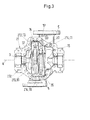
- Fig. 2 shows a perspective view of an embodiment of an inventive axially divided pump, which is generally designated by the reference numeral 1.
- the pump 1 comprises a housing 2, which is divided axially, and a lower part 21 and a cover 22 includes.
- Fig. 3 shows a plan view of the lower part 21 of the housing 2 of this embodiment.
- the housing 2 comprises an inlet 5 for sucking a fluid to be delivered and an outlet 6 for the fluid.
- the pump 1 comprises a rotatable shaft 3 whose longitudinal direction defines an axial direction A.
- On the shaft 3 is at least one impeller 4, in the present case, there are two wheels 4, rotatably mounted, which promotes the fluid from the inlet 5 to the outlet 6.
- a bearing device 7 is provided at both ends with respect to the axial direction A of the pump 1 to support the shaft 3 of the pump 1.
- the representation according to the left bearing device 7 ( Fig. 1 ) is further provided with a coupling 8 which is connectable to a drive, not shown, which causes the shaft 3 of the pump 1 in rotation.
- axially divided pump 1 or axially split housing 2 means, as is generally customary, that the housing 2 is divided parallel to the longitudinal direction of the shaft 3, ie in a plane which contains the longitudinal axis of the shaft 3.
- Fig. 2 and Fig. 3 illustrated pump 1 to an axially divided multi-stage - here two-stage centrifugal pump, which is designed einflutig and in a so-called Between-Bearing arrangement, ie the wheels 4 are located between the storage devices 7.
- the invention is not limited to such pump types is, but also suitable for all other pumps with axially split housing 1, for example, single-stage pumps, ie those with only one impeller 4, double-flow pumps with single-stage or multi-stage design or pump types other than centrifugal pumps.
- the housing 2 of the pump 1 is closed in each case by a side cover 9, which simultaneously constitutes the end cover of a mechanical shaft seal in the present case.
- the cover 22 and the lower part 21 of the housing 2 are in direct contact with each other in the mounted state, that is, no flat gasket is provided between these two parts, which prevents direct contact between the lower part 21 and the cover 22.
- the lower part 21 comprises a first flange 211, which extends in the assembled state in the plane of the axial pitch of the housing 2 and whose upper surface according to the illustration forms a first sealing surface 212.
- the cover 22 is provided with a second flange 221, which extends in the assembled state in the plane of the axial pitch of the housing 2 and its lower surface according to the representation ( Fig. 2 ) forms a second sealing surface 222.
- first sealing surface 212 and the second sealing surface 222 are in direct contact with each other to form a sealing connection between the lower part 21 and the cover 22 of the housing 2.
- first sealing groove 213 is provided which extends from the left side cover 9 according to the illustration in the axial direction A following the inner contour of the pump 1 to the other side cover 9.
- This first seal groove 213 is provided on both sides of the shaft 3.
- a first cord-shaped sealing element 10 is inserted, which extends over the entire length of the first seal groove 213 and which seals the interior of the pump 1 from the environment. Therefore, the first seal groove 213 is also referred to as the outer seal groove 213.
- the first cord-shaped sealing element 10 usually has a round cross section, as it is known for example from commercially available O-rings. Of course, it is also possible that the cord-shaped sealing element another Cross-section, for example, a rectangular and in particular a square cross-section. In this case, the first string-shaped sealing element 10 is dimensioned with respect to its diameter so that it protrudes beyond the edge of the first sealing groove 213 in the unassembled state. When mounting the cover 22 on the lower part 21, the first cord-shaped sealing element 10 is thus elastically deformed and thus ensures a reliable seal between the lower part 21 and the cover 22 of the housing second
- the attachment of the cover 22 on the lower part 21 is preferably carried out by means of bolts or screws, which by the provided in the first sealing surface 212 holes or tapped holes (without reference numerals in Fig. 2 and Fig. 2 ), so that the lower part 21 and the cover 22 are screwed tightly and sealingly together.
- the pump 1 is configured in the present embodiment as a two-stage centrifugal pump.
- a suction chamber 15 of the pump 1 there is the suction pressure, which is applied to the inlet 5 of the pump 1, in an outlet chamber 16 prevails the delivery pressure, with which the fluid is available at the outlet 6 of the pump.
- an intermediate space 17 there is an intermediate pressure, the amount of which is between the suction pressure and the delivery pressure.
- the fluid to be delivered, coming from the inlet 5 is conveyed through the right-hand impeller 4 of the first stage into the intermediate space 17 and brought to the intermediate pressure.
- the left-hand impeller 4 of the second stage conveys the fluid into the outlet space 16, where it is then under the delivery pressure and is available at the outlet 6 of the pump 1.
- At least one second seal groove 214 is provided, which is also referred to as inner seal groove 214, because it serves to seal between different pressure chambers in the pump, in the present
- Embodiment is the second sealing groove 214 of the seal between the suction chamber 15 and the gap 17.
- the second seal groove 214 is also provided on both sides of the shaft 3.
- a second cord-shaped sealing element 11 is inserted, which extends over the entire length of the second seal groove 214.
- the second cord-shaped sealing element 11 usually has a round cross section, as it is known for example from commercially available O-rings.
- the second cord-shaped sealing element has a different cross-section, for example a rectangular and in particular a square cross-section.
- the second cord-shaped sealing element 11 is dimensioned with respect to its diameter so that it protrudes beyond the edge of the second sealing groove 214 in the unassembled state.
- first and / or the second sealing groove 213 or 214 as well as optionally further sealing grooves in the cover 22 of the housing 2, or to provide sealing grooves both in the lower part 21 and in the cover 22.
- all sealing grooves 213, 214 are provided only in the lower part 21.
- the second seal groove 214 extends in the radial direction perpendicular to the axial direction.
- the second seal groove 214 is connected through a junction 20 with the first seal groove 213 so that the two seal members 10 and 11 can cooperate.
- Fig. 4 in an enlarged and schematic representation of the detail I from Fig. 3 the area of the junction 20 of the second seal groove 214 in the first seal groove 213.
- the first and the second cord-shaped sealing element 10 and 11 respectively shown hatched.
- a connecting element 50 is provided in the junction 20.
- Fig. 5 a perspective view of an embodiment of the connecting element 50 and Fig. 6 a cross section through the connecting element 50, wherein in Fig. 6 the two cord-shaped sealing elements 10, 11 are inserted into the connecting element 50.
- the connecting element 50 has a rectangular bottom 53 and a parallel rectangular top 52, which are connected by two end surfaces 54. Its longitudinal extent is designated as length L.
- the connecting element 50 has two lateral recesses 51, which extend in each case over the entire length L between the end surfaces 54.
- the lateral recesses 51 are configured to receive a respective cord-shaped sealing element 10 or 11 and may be identical or different depending on the sealing element.
- the two lateral recesses 51 extend parallel to each other, so that the two cord-shaped sealing elements 10 and 11 are parallel or at least substantially parallel to each other after they are inserted into the recesses 51 in the region of the connecting piece 50.
- Each of the recesses 51 has an inner contour 55, which respectively follows the lateral surface 12 or 13 of the respective cord-shaped sealing element 10 or 11, which is inserted into the recess 51.
- the sealing elements 10, 11 a circular Querschnitss Solution - as in Fig. 6
- the inner contour 55 of the recesses 51 is also curved in an arc of a circle perpendicular to the longitudinal extent of the recess 51, wherein the radius of curvature substantially corresponds to that of the respective sealing element 10, 11.
- the depth T of the recess 51 perpendicular to its longitudinal extension can be adjusted depending on the application. However, in the case of sealing elements 10, 11 having a circular cross-section, it has proven to be sufficient in practice proven when the recess 51 at most half, preferably less than half of the lateral surface 12, 13 of the sealing member 10, 11 contacted. Depending on the application and the design of the respective sealing element, the depth T may be different for the two recesses 51. Also, the curvature of the inner contour 55 may be different for the two recesses 51. In the present embodiment, the depth T and the curvature of the inner contour 55 for the two recesses 51 is the same.
- an extension 60 of the two sealing grooves 213, 214 is provided in the region of the junction 20, in which the connecting element 50 can be inserted.
- the first cord-shaped sealing element 10 is continuous in the region of the connecting element 50, that is to say it does not have to be cut open or manipulated in any other way, but is simply inserted into the corresponding recess 51.
- the second cord-shaped sealing element 11 has in the region of the junction 20 has an end 14. This straight end 14 is inserted into the other of the two recesses 51 and thus extends in the region of the connecting element 50 parallel to the first cord-shaped sealing element 10.
- the second sealing member 11 with respect its length preferably so dimensioned that its end 14 terminates after insertion into the recess 51 is substantially flush with the end surface 54 of the connecting element 50.
- Fig. 4 illustrated arrangement allows the replacement of otherwise T-shaped connections or contact points between separate sealing elements 10, 11 by a particularly good sealing connection, in which the two sealing elements 10, 11 are guided parallel to each other in the region of the junction 20.
- the suitable length L for the connecting element 50 results depending on the application, but it has been proven in practice when the recesses 51 each have a length L which is at least as large as three times the diameter of the inserted sealing element 10 and 11 respectively ,
- the connecting element 50 is preferably made of a plastic and may for example be an injection molded part. While primarily the shape of the connecting element 50 for the best possible contact with the respective sealing element 10 and 11 is authoritative, it may still be advantageous if the connecting element 50 is elastically deformable.
- Suitable materials for both the first cord-shaped sealing element 10 and for the second cord-shaped sealing element 11 are in particular all materials known per se, which are used for such seals, in particular elastomers such as nitrile rubber and especially nitrile-butadiene rubber (NBR).
- elastomers such as nitrile rubber and especially nitrile-butadiene rubber (NBR).
- Fig. 7 illustrated in a too Fig. 4 a particularly preferred variant of the embodiment of the inventive pump 1.
- the reference numerals have the same meaning for the same or functionally equivalent parts.
- the junction 20 additionally has a recess 70 which extends parallel to the longitudinal extent or to the longitudinal extent of the connecting element 50.
- an elastic biasing element 71 is preferably inserted, which exerts a bias on one - here the second - cord-shaped sealing element 11. This bias is transmitted through the connecting element 50 also on the other - here the first - sealing element 10.
- the arrangement of the biasing member 71 and the recess 70 is such that the bias is generated in the direction of decreasing pressure, ie in the illustration according to Fig. 7 downward.
- the biasing member 71 is resilient, and particularly preferably designed as a spring.
- the spring 71 extends parallel to the second string-shaped sealing element 11 and is dimensioned so that it is wider than the width D of the recess 70 with respect to the radial direction.
- the biasing member 71 ensures an additional contribution that even at lower operating pressures, so for example when starting the pump 1, immediately a sufficient sealing effect between the housing 2 of the pump 1 and the environment or between the suction chamber 15 and Gap 17 is realized. Also with regard to the long-term operation of the pump 1, the biasing element 71 is advantageous. Namely, if it comes with increasing operating time of the pump 1 to degradation, fatigue or other changes or wear of the cord-shaped sealing elements 10 and 11, these can be compensated by the action of the biasing member 71, because this the cord-shaped sealing elements 10 and 11 reliably against the Connecting element 50 and the wall of the sealing groove 214 presses.
- the improved sealing effect at the connection point between individual sealing elements 10, 11 is in particular also with regard to a highest possible operating pressure of the pump 1 advantageous.
- the pump 1 for example in one embodiment as a centrifugal pump, can be designed with a design pressure of at least 50 bar and preferably at least 100 bar.
Landscapes
- Engineering & Computer Science (AREA)
- General Engineering & Computer Science (AREA)
- Mechanical Engineering (AREA)
- Physics & Mathematics (AREA)
- Geometry (AREA)
- Structures Of Non-Positive Displacement Pumps (AREA)
- Details Of Reciprocating Pumps (AREA)
Abstract
Description
- Die Erfindung betrifft eine axial geteilte Pumpe zum Fördern eines Fluids gemäss dem Oberbegriff des unabhängigen Patentanspruchs.
- Axial geteilte Pumpen, die auch als horizontal geteilte Pumpen bezeichnet werden, sind Pumpen, bei denen das Gehäuse parallel zur Achse der Welle geteilt ist und somit ein Unterteil und einen Deckel aufweist. Sowohl das Unterteil als auch der Deckel weisen jeweils einen Flansch auf, die zur Montage der Pumpe aufeinandergelegt und dann fest miteinander verbunden, beispielsweise verschraubt, werden.
- Axial geteilte Pumpen sind seit langem wohl bekannt und werden in zahlreichen Ausführungsformen meist als Zentrifugalpumpen hergestellt, beispielsweise als ein- oder doppelflutige Pumpen und als einstufige oder mehrstufige Pumpen. Dabei kann das Laufrad der Pumpe zwischen zwei Lagern angeordnet sein (Between-bearing-Pump). Auch der Anwendungsbereich dieser Pumpen ist sehr breit, sie werden zum Beispiel in der Öl- und Gasindustrie oder in der Wasserindustrie oder im Bereich der Energieerzeugung eingesetzt. Häufig sind axial geteilte Pumpen für einen hohen Betriebsdruck oder grosse Volumenströme ausgelegt und eignen sich zum Pumpen über grosse geodätische Höhen, zum Fördern durch Wasser- oder Ölpipelines oder zur Meerwasserentsalzung mittels Umkehrosmose.
- Bei axial geteilten Pumpen kommt natürlich der Abdichtung zwischen dem Unterteil und dem Deckel des Gehäuses entlang der beiden Flansche eine entscheidende Bedeutung zu. Hierbei gilt es zum einen, den Innenraum der Pumpe gegen die Umgebung abzudichten und zum anderen im Innenraum der Pumpe solche Druckräume gegeneinander abzudichten, in denen im Betriebszustand unterschiedliche Drücke herrschen, wie dies beispielsweise bei mehrstufigen Pumpen der Fall ist.
- Zum Dichten zwischen dem Unterteil und dem Deckel ist es bekannt, insbesondere für Anwendungen mit hohem Druck, eine Flachdichtung zwischen den beiden Flanschen einzulegen, sodass sich die beiden Flansche im montierten Zustand nicht direkt berühren, sondern beidseitig die Flachdichtung kontaktieren. Solche Flachdichtungen erfordern eine hohe Vorspannung, insbesondere auch, um die erforderliche Flächenpressung zwischen Unterteil, Deckel und der Flachdichtung zu erzielen.
- Eine alternative Technologie zur Abdichtung zwischen dem Unterteil und dem Deckel, wie sie beispielsweise auch in der
WO-A-2014/083374 beschrieben ist, besteht darin, die Flansche des Unterteils und des Oberteils ohne dazwischenliegende Dichtung direkt aufeinander zu montieren. Die jeweiligen Oberflächen der beiden Flansche bilden dann Dichtflächen, die im montierten Zustand direkten Kontakt miteinander haben. Bei dieser Lösung ist üblicherweise in dem Unterteil oder in dem Deckel oder im Unterteil und im Deckel zumindest eine äussere Dichtungsnut vorgesehen, die sich beidseitig der Welle über die gesamte axiale Länge der Pumpe erstreckt und in die ein schnurförmiges Dichtungselement, beispielsweise ein O-ring-ähnliches Dichtungselement eingelegt ist. Nach Einlegen des schnurförmigen Dichtungselements in die Dichtungsnut werden das Unterteil und der Deckel fest miteinander verschraubt, sodass die Dichtflächen der beiden Flansche in direktem Kontakt miteinander stehen und das schnurförmige Dichtungselement in der Dichtungsnut elastisch verformt wird, um so eine zuverlässige Abdichtung zu gewährleisten. - Da bei dieser Lösung keine Flachdichtung zwischen dem Flansch des Unterteils und dem des Deckels eingelegt ist, haben die Verschraubungen, mit denen das Unterteil und der Deckel aneinander befestigt werden, eine deutlich geringere Last zu tragen. Hieraus resultieren einige Vorteile: So können die Flansche, welche die Dichtflächen bilden, deutlich dünner und schmaler ausgestaltet werden, es wird weniger Material für die Flansche benötigt, was eine Kosten- und eine Gewichtsersparnis mit sich bringt, für die Verschraubung von Unterteil und Deckel können kleinere Schrauben bzw. Bolzen verwendet werden, diese können daher auch näher an der hydraulischen Kontur platziert werden. Zudem lässt die Verwendung der schnurförmigen Dichtungselemente im Vergleich zu den Flachdichtungen eine höhere Deformation des Gehäuses zu. Dies ist inbesonder bei mehrstufigen Pumpen von Vorteil, weil sich hierdurch die Leckage zwischen verschiedenen Druckräumen in der Pumpe, in welchen unterschiedliche Drücke herrschen, deutlich reduzieren oder sogar vermeiden lässt.
- Die schnurförmigen Dichtungselemente sind üblicherweise aus einem Elastomer gefertigt, wie es auch für handelsübliche O-Ringdichtungen verwendet wird, beispielsweise aus dem Nitrilkautschuk Nitril-Butadien-Kautschuk (NBR: Nitrile Butadiene Rubber).
- Bei den meisten Anwendungen sind mehr als eine Dichtungsnut mit jeweils einem eingelegten schnurförmigen Dichtungselement vorgesehen. So kann beispielsweise ein inneres schnurförmiges Dichtungselement zur Abdichtung des Saugraums gegen den Druckraum vorgesehen sein und ein äusseres schnurförmiges Dichtungselement, welches den Innenraum der Pumpe gegen die Aussenwelt, also den Umgebungsdruck abdichtet. Inbesondere bei mehrstufigen Pumpen können zusätzliche Dichtungsnuten mit jeweils eingelegten schnurförmigen Elementen vorgesehen sein, um die verschiedenen Druckräume, in denen im Betriebszustand unterschiedliche Drücke herrschen, gegeneinander abzudichten.
- Bei der Auslegung solcher Dichtungen mittels schnurförmiger Dichtungselemente ist man bemüht, die individuellen schnurförmigen Dichtungselemente möglichst als geschlossene also insbesondere ringförmige Dichtungselemente zu gestalten, weil die Verbindungs- oder Stossstellen zwischen individuellen schnurförmigen Dichtungselementen potenziell zu Leckagen führen können, insbesondere dann, wenn die Pumpe für einen hohen Betriebsdruck von beispielsweise bis zu 100 bar ausgelegt ist. Allerdings ist es rein konstruktiv nicht möglich, ausschliesslich in sich geschlossene Dichtungsschnüre vorzusehen. Es wird immer solche kritischen Stellen geben, an denen zwei individuelle Dichtungselemente aneinander grenzen oder verbunden werden müssen und für die erwünschte Abdichtung zusammenwirken müssen.
- So muss beispielsweise bei einer mehrstufigen Pumpe ein inneres schnurförmiges Dichtungselement, welches der Abdichtung zwischen zwei Stufen dient, mit dem in der äusseren Dichtungsnut eingelegten Dichtungselement verbunden werden. Diese Verbindung muss zuverlässig sein und sollte im Falle von Wartungsarbeiten ohne grossen Aufwand oder Spezialwerkzeuge reparabel sein.
- In
Fig. 1 ist in einer schematischen Darstellung eine solche kritische Stelle veranschaulicht, an der zwei schnurförmige Dichtungselemente 101 und 103 an einer T-förmigen Verbindungsstelle aneinanderstossen. Die schnurförmigen Dichtungselemente 101, 103 haben üblicherweise einen runden, insbesondere kreisförmigen Querschnitt senkrecht zu ihrer Längserstreckung. An einer T-förmigen Verbindungsstelle stösst dann die planare - also ungewölbte - Endfläche 102 des Dichtungselements 101 auf die gekrümmte Mantelfläche 104 des anderen Dichtungselements 103. Hierbei kommt es zur Ausbildung von im Wesentlichen dreieckförmigen Bereichen 105, in denen die beiden Dichtungselemente 101 und 103 keinen Kontakt mehr haben. Diese Bereiche 105 können zu Leckagen führen, welche die Wirkung der Dichtungsanordnung negativ beeinflussen. - Ausgehend von dem beschriebenen Stand der Technik ist es daher eine Aufgabe der Erfindung eine axial geteilte Pumpe zum Fördern eines Fluids vorzuschlagen, bei welcher eine zuverlässige Dichtung auch an Verbindungsstellen zwischen Dichtungselementen gewährleistet werden kann.
- Der diese Aufgabe lösenden Gegenstand der Erfindung ist durch die Merkmale des unabhängigen Patentanspruchs gekennzeichnet.
- Erfindungsgemäss wird also eine axial geteilte Pumpe zum Fördern eines Fluids vorgeschlagen, mit einem axial geteilten Gehäuse, welches ein Unterteil und einen Deckel umfasst, wobei das Unterteil eine erste Dichtfläche aufweist und der Deckel eine zweite Dichtfläche, wobei das Unterteil und der Deckel derart aneinander befestigbar sind, dass die beiden Dichtflächen direkten Kontakt miteinander haben, wobei in den Dichtflächen eine erste Dichtungsnut zur Aufnahme eines ersten schnurförmigen Dichtungselements vorgesehen ist, sowie eine zweite Dichtungsnut zur Aufnahme eines zweiten schnurförmigen Dichtungselements, welche zweite Dichtungsnut durch eine Einmündung mit der ersten Dichtungsnut verbunden ist, und wobei in der Einmündung ein Verbindungselement vorgesehen ist, welches zwei laterale Ausnehmungen zur Aufnahme jeweils eines der schnurförmigen Dichtungselemente aufweist, wobei die Ausnehmungen so angeordnet und ausgestaltet sind, dass die beiden schnurförmigen Dichtungselemente im Bereich des Verbindungselements im wesentlichen parallel verlaufen können.
- Vorzugsweise ist dabei in die erste Dichtungsnut ein erstes schnurförmiges Dichtungselement eingelegt und in die zweite Dichtungsnut ist ein zweites schnurförmiges Dichtungselement eingelegt, und jede der zwei lateralen Ausnehmungen des Verbindungselements nimmt jeweils eines der schnurförmigen Dichtungselemente auf.
- Die Erfindung basiert auf der anhand von
Fig. 1 erläuterten Erkenntnis, dass insbesondere an solchen Kontaktstellen zwischen zwei separaten Dichtungselementen Probleme auftreten können, an denen eine planare - also nicht gewölbte- Endläche des einen Dichtungselements an einer gekrümmten Fläche, beispielsweise der Mantelfläche eines im Querschnitt kreisförmigen zweiten Dichtungselements anliegt. Diese Geometrie bedingt eine reduzierte Kontaktfläche zwischen den beiden Dichtungselementen, sodass hier leichter Leckagen auftreten können. - Dadurch, dass erfindungsgemäss in der Einmündung das Verbindungselement mit den beiden lateralen Ausnehmungen vorgesehen ist, können die beiden schnurförmigen Dichtungselemente in diesem Bereich parallel zueinander angeordnet werden und haben so über das Verbindungselement eine deutlich vergrösserte effektive Kontaktfläche, was zu einer erheblich verbesserten Dichtwirkung an dieser Verbindungsstelle führt. Es lässt sich also insbesondere auch vermeiden, dass an einer eigentlich T-förmigen Verbindungsstelle eine planare Endfläche eines Dichtungselements auf die gekrümmte Fläche eines anderen Dichtungselements trifft.
- Durch die erindungsgemässe Ausgestaltung kann das Zusammenwirken der Dichtungselemente deutlich verbessert werden, sodass auch insbesondere bei sehr hohem Betriebsdruck eine äusserst zuverlässige Dichtung zwischen den einzelnen Bereichen der Pumpe gewährleistet ist.
- Gemäss einem bevorzugten Ausführungsbeispiel nimmt eine der beiden Ausnehmungen ein gerades Ende einer der schnurförmigen Dichtungselemente auf. Diese Anordnung kann die T-förmige Verbindungsstelle zwischen zwei schnurförmigen Dichtungselementen ersetzten. Während das erste Dichtungselement in die eine der beiden Ausnehmungen des Verbindungselements eingelegt wird und durchgängig ist, wird das Ende des rechtwinklig dazu verlaufenden zweiten Dichtungselements in die andere Ausnehmung des Verbindungselements geführt und verläuft dort parallel zu dem ersten Dichtungselement.
- Eine besonders vorteilhafte Massnahme besteht darin, wenn jede der Ausnehmungen eine innere Kontur aufweist, welche jeweils der Mantelfläche des jeweiligen schnurförmigen Dichtungselements folgt. Durch diese Massnahme kann sich jedes Dichtungselement jeweils optimal an die innere Kontur der Ausnehmung anschmiegen, woraus eine möglichst grosse Kontaktfläche und damit eine besonders gute Dichtwirkung resultiert.
- In der Praxis hat es sich als vorteilhaft erwiesen, wenn die Ausnehmungen in dem Verbindungselement jeweils eine Länge aufweisen, die mindestens so gross ist, wie der dreifache Durchmesser des eingelegten Dichtungselements.
- Gemäss einem bevorzugten Ausführungsbeispiel ist jede Dichtungsnut im Unterteil des Gehäuses vorgesehen, was insbesondere eine einfachere Fertigung und eine leichtere Montage ermöglicht.
- Vorzugsweise ist das Verbindungselement aus einem Kunststoff gefertigt, beispielsweise ein Spritzgussteil.
- Gemäss einem bevorzugten Ausführungsbeispiel ist die erste Dichtungsnut zur Abdichtung des Innenraums der Pumpe gegen den Umgebungsdruck angeordnet. Da diese Dichtungsnut über die gesamte axiale Länge der Pumpe durchgängig - also ohne Unterbrechung - gestaltet werden kann, lässt sich hiermit eine besonders zuverlässige Abdichtung zwischen dem Innenraum der Pumpe und der Umgebung realisieren.
- Die zweite Dichtungsnut ist vorzugsweise zur Abdichtung zwischen zwei Druckräumen in der Pumpe angeordnet, in welchen im Betriebszustand verschiedene Drücke herrschen.
- Eine weitere vorteilhafte Massnahme besteht darin, dass die Einmündung eine Ausnehmung aufweist, die sich parallel zur Längsausdehnung des Verbindungselements erstreckt.
- In diese Ausnehmung kann dann optional ein elastisches Vorspannelement eingelegt sein, welches eine Vorspannung auf eines der schnurförmige Dichtungselemente ausübt. Diese Massnahme bietet den Vorteil, dass auch schon bei kleineren Betriebsdrücken, also beispielsweise beim Anfahren der Pumpe, von Beginn an eine sehr gute Dichtwirkung erzielt wird. Ferner resultiert der Vorteil, dass nach längerer Betriebsdauer der Pumpe, wenn Degradationen oder sonstige Veränderungen in den schnurförmigen Dichtungselementen auftreten können, das elastische Vorspannelement diese Veränderungen kompensiert und die Dichtungselemente zuverlässig gegen die Wandung der Ausnehmung des Verbindungselements drückt. Auch bei der Montage der Pumpe ist diese Massnahme vorteilhaft, weil beispielsweise ein freies Ende des schnurförmigen Dichtungselements im Bereich der Einmündung quasi eingeklemmt und somit in der gewünschten Position gehalten wird.
- Vorzugsweise ist das Vorspannelement federelastisch und erstreckt sich parallel zu einem der schnurförmigen Dichtungselemente. Besonders bevorzugt ist das Vorspannelement als Feder ausgestaltet.
- Bezüglich des Materials ist es bevorzugt, wenn die schnurförmigen Dichtungselemente aus einem Elastomer, insbesondere aus einem Nitrilkautschuk, speziell aus Nitril-Butadien-Kautschuk NBR gefertigt sind.
- Die erfindungsgemässe Pumpe eignet sich insbesondere auch für sehr hohe Betriebsdrücke und kann vorzugsweise als Zentrifugalpumpe mit einem Auslegungsdruck von mindestens 50 bar, vorzugsweise mindestens 100 bar ausgestaltet werden.
- In einer bevorzugten Anwendung ist die erfindungsgemässe Pumpe als mehrstufige Pumpe ausgestaltet.
- Weitere vorteilhafte Massnahmen und Ausgestaltungen der Erfindung ergeben sich aus den abhängigen Ansprüchen.
- Im Folgenden wird die Erfindung anhand von Ausführungsbeispielen und anhand der Zeichnung näher erläutert. In der Zeichnung zeigen, teilweise im Schnitt:
- Fig. 1:
- eine schematische Darstellung einer T-förmigen Kontaktstelle zwischen zwei Dichtungselementen,
- Fig.2:
- ein perspektivische Darstellung eines Ausführungsbeispiels einer erfindungsgemässen Pumpe, wobei der Deckel entfernt und nur symbolisch angedeutet ist,
- Fig. 3:
- eine Aufsicht auf das Unterteil des Gehäuses des Ausführungsbeispiels aus
Fig. 2 , - Fig. 4:
- eine schematisierte Darstellung des Details I aus
Fig. 3 , - Fig. 5:
- eine perspektivische Darstellung eines Ausführungsbeispiels eines Verbindungselements,
- Fig. 6:
- einen Querschnitt durch das Verbindungselement mit eingelegten Dichtungselementen, und
- Fig. 7:
- eine Variante für das Ausführungsbeispiel aus
Fig. 2 in einer zuFig. 4 analogen Darstellung. -
Fig. 2 zeigt in einer perspektivischen Darstellung ein Ausführungsbeispiel einer erfindungsgemässen axial geteilten Pumpe, die gesamthaft mit dem Bezugszeichen 1 bezeichnet ist. Die Pumpe 1 umfasst ein Gehäuse 2, das axial geteilt ist, und ein Unterteil 21 sowie einen Deckel 22 umfasst. Zum besseren Verständnis ist inFig. 2 der Deckel 22 entfernt und nur symbolisch angedeutet.Fig. 3 zeigt eine Aufsicht auf das Unterteil 21 des Gehäuses 2 dieses Ausführungsbeispiels. - Das Gehäuse 2 umfasst einen Einlass 5 zum Ansaugen eines zu fördernden Fluids sowie einen Auslass 6 für das Fluid. Ferner umfasst die Pumpe 1 eine rotierbare Welle 3, deren Längsrichtung eine axiale Richtung A festlegt. Auf der Welle 3 ist mindestens ein Laufrad 4, im vorliegenden Fall sind es zwei Laufräder 4, drehfest montiert, welche das Fluid vom Einlass 5 zum Auslass 6 fördert. Ferner ist an den beiden Enden bezüglich der axialen Richtung A der Pumpe 1 jeweils eine Lagervorrichtung 7 vorgesehen, um die Welle 3 der Pumpe 1 zu lagern. Die darstellungsgemäss linke Lagervorrichtung 7 (
Fig. 1 ) ist ferner mit einer Kupplung 8 versehen, die mit einem nicht dargestellten Antrieb verbindbar ist, welcher die Welle 3 der Pumpe 1 in Rotation versetzt. - Mit dem Begriff axial geteilte Pumpe 1 bzw. axial geteiltes Gehäuse 2 ist wie allgemein üblich gemeint, dass das Gehäuse 2 parallel zur Längsrichtung der Welle 3 geteilt ist, also in einer Ebene, welche die Längsachse der Welle 3 enthält.
- Im speziellen handelt es sich bei der in den
Fig. 2 undFig. 3 dargestellten Pumpe 1 um eine axial geteilte mehrstufige - hier zweistufige Zentrifugalpumpe, die einflutig ausgestaltet ist und in einer sogenannte Between-Bearing-Anordnung, d. h. die Laufräder 4 befinden sich zwischen den Lagervorrichtungen 7. Es versteht sich, dass die Erfindung nicht auf solche Pumpentypen beschränkt ist, sondern auch für alle anderen Pumpen mit axial geteiltem Gehäuse 1 geeignet ist, beispielsweise einstufige Pumpen, also solche mit nur einem Laufrad 4, doppelflutige Pumpen mit einstufiger oder mehrstufiger Ausgestaltung oder andere Pumpentypen als Zentrifugalpumpen. - Bezüglich der axialen Richtung A ist das Gehäuse 2 der Pumpe 1 jeweils durch einen Seitendeckel 9 verschlossen, der im vorliegenden Fall gleichzeitig den Abschlussdeckel einer mechanischen Wellendichtung darstellt.
- Der Deckel 22 und das Unterteil 21 des Gehäuses 2 sind im montierten Zustand in direktem Kontakt miteinander, das heisst zwischen diesen beiden Teilen ist keine Flachdichtung vorgesehen, welche den direkten Kontakt zwischen dem Unterteil 21 und dem Deckel 22 verhindert. Dazu umfasst das Unterteil 21 einen ersten Flansch 211, der sich im montierten Zustand in der Ebene der axialen Teilung des Gehäuses 2 erstreckt und dessen darstellungsgemäss obere Oberfläche eine erste Dichtfläche 212 bildet. In sinngemäss gleicher Weise ist der Deckel 22 mit einem zweiten Flansch 221 versehen, der sich im montierten Zustand in der Ebene der axialen Teilung des Gehäuses 2 erstreckt und dessen darstellungsgemäss untere Oberfläche (
Fig. 2 ) eine zweite Dichtfläche 222 bildet. - Nach Montage des Deckels 22 auf dem Unterteil 21 stehen die erste Dichtfläche 212 und die zweite Dichtfläche 222 in direktem Kontakt miteinander, um eine dichtende Verbindung zwischen dem Unterteil 21 und dem Deckel 22 des Gehäuses 2 zu bilden. In der ersten Dichtfläche 212 des Unterteils 21 ist eine erste Dichtungsnut 213 vorgesehen, welche sich von dem darstellungsgemäss linken Seitendeckel 9 in axialer Richtung A der inneren Kontur der Pumpe 1 folgend bis zu dem anderen Seitendeckel 9 erstreckt. Diese erste Dichtungsnut 213 ist auf beiden Seiten der Welle 3 vorgesehen. In die erste Dichtungsnut 213 ist ein erstes schnurförmiges Dichtungselement 10 eingelegt, welches sich über die gesamte Länge der ersten Dichtungsnut 213 erstreckt und welches den Innenraum der Pumpe 1 gegenüber der Umgebung abdichtet. Daher wird die erste Dichtungsnut 213 auch als äussere Dichtungsnut 213 bezeichnet. Das erste schnurförmige Dichtungselement 10 hat üblicherweise einen runden Querschnitt, so wie es beispielsweise von handelsüblichen O-Ringen bekannt ist. Natürlich ist es auch möglich, dass das schnurförmige Dichtungselement einen anderen Querschnitt aufweist, beispielsweise einen rechteckigen und insbesondere einen quadratischen Querschnitt. Dabei ist das erste schnurförmige Dichtungselement 10 bezüglich seines Durchmessers so bemessen, dass es im unmontierten Zustand über den Rand der ersten Dichtungsnut 213 hinaussteht. Bei der Montage des Deckels 22 auf das Unterteil 21 wird somit das erste schnurförmige Dichtungselement 10 elastisch verformt und sorgt somit für eine zuverlässige Abdichtung zwischen dem Unterteil 21 und dem Deckel 22 des Gehäuses 2.
- Die Befestigung des Deckels 22 auf dem Unterteil 21 erfolgt vorzugsweise mittels Bolzen oder Schrauben, welche durch die in der ersten Dichtfläche 212 vorgesehene Bohrungen oder Gewindebohrungen (ohne Bezugszeichen in
Fig. 2 und Fig. 2 ) greifen, sodass das Unterteil 21 und der Deckel 22 fest und dichtend miteinander verschraubt sind. - Die Pumpe 1 ist im vorliegenden Ausführungsbeispiel als zweistufige Zentrifugalpumpe ausgestaltet. Es existieren somit im Innern der Pumpe 1 mehrere Druckräume, in denen im Betriebszustand unterschiedliche Drücke herrschen (siehe
Fig. 3 ): In einem Saugraum 15 der Pumpe 1 herrscht der Saugdruck, der am Einlass 5 der Pumpe 1 anliegt, in einem Auslassraum 16 herrscht der Förderdruckdruck, mit welchem das Fluid am Auslass 6 der Pumpe zur Verfügung steht. In einem Zwischenraum 17 herrscht ein Zwischendruck, dessen Betrag zwischen dem Saugdruck und dem Förderdruck liegt. Bei der zweistufigen Pumpe 1 wird das zu fördernde Fluid vom Einlass 5 kommend durch das darstellungsgemäss rechte Laufrad 4 der ersten Stufe in den Zwischenraum 17 gefördert und dabei auf den Zwischendruck gebracht. Von dem Zwischenraum 17 fördert das darstellungsgemäss linke Laufrad 4 der zweiten Stufe das Fluid in den Auslassraum 16, wo es dann unter dem Förderdruck steht und am Auslass 6 der Pumpe 1 zur Verfügung steht. - Zur Abdichtung zwischen den verschiedenen Druckräumen in der Pumpe 1 sind weitere Dichtungsnuten vorgesehen. In dem Unterteil 21 ist mindestens eine zweite Dichtungsnut 214 vorgesehen, welche auch als innere Dichtungsnut 214 bezeichnet wird, weil sie der Abdichtung zwischen verschiedenen Druckräumen in der Pumpe dient, im vorliegenden
- Ausführungsbeispiel dient die zweite Dichtungsnut 214 der Abdichtung zwischen dem Saugraum 15 und dem Zwischenraum 17. Wie dies insbesondere
Fig. 3 zeigt, ist die zweite Dichtungsnut 214 ebenfalls auf beiden Seiten der Welle 3 vorgesehen. In die zweite Dichtungsnut 214 ist ein zweites schnurförmiges Dichtungselement 11 eingelegt, welches sich über die gesamte Länge der zweiten Dichtungsnut 214 erstreckt. Auch das zweite schnurförmige Dichtungselement 11 hat üblicherweise einen runden Querschnitt, so wie es beispielsweise von handelsüblichen O-Ringen bekannt ist. Natürlich ist es auch möglich, dass das zweite schnurförmige Dichtungselement einen anderen Querschnitt aufweist, beispielsweise einen rechteckigen und insbesondere einen quadratischen Querschnitt. Dabei ist das zweite schnurförmige Dichtungselement 11 bezüglich seines Durchmessers so bemessen, dass es im unmontierten Zustand über den Rand der zweiten Dichtungsnut 214 hinaussteht. Bei der Montage des Deckels 22 auf das Unterteil 21 wird somit das zweite schnurförmige Dichtungselement 11 elastisch verformt und sorgt somit für eine zuverlässige Abdichtung zwischen dem Saugraum 15 und dem Zwischenraum 17. - Alternativ ist es auch möglich, die erste und/oder die zweite Dichtungsnut 213 bzw. 214 so wie gegebenenfalls weitere Dichtungsnuten im Deckel 22 des Gehäuses 2 vorzusehen, oder sowohl im Unterteil 21 als auch im Deckel 22 Dichtungsnuten vorzusehen. Aus fertigungs- und montagetechnischen Gründen ist es bevorzugt, wenn alle Dichtungsnuten 213, 214 nur im Unterteil 21 vorgesehen sind.
- Wie dies insbesondere
Fig. 3 zeigt, erstreckt sich die zweite Dichtungsnut 214 in der zur axialen Richtung senkrechten radialen Richtung. Die zweite Dichtungsnut 214 ist durch eine Einmündung 20 mit der ersten Dichtungsnut 213 verbunden, damit die beiden Dichtungselemente 10 und 11 zusammenwirken bzw. verbunden werden können. Dies wird im Folgenden näher erläutert. Dazu zeigtFig. 4 in einer vergrösserten und schematisierten Darstellung des Details I ausFig. 3 den Bereich der Einmündung 20 der zweiten Dichtungsnut 214 in die erste Dichtungsnut 213. Zum besseren Verständnis sind inFig. 4 das erste und das zweite schnurförmige Dichtungselement 10 bzw. 11 jeweils schraffiert dargestellt. - Erfindungsgemäss ist in der Einmündung 20 ein Verbindungselement 50 vorgesehen. Zum besseren Verständnis zeigt
Fig. 5 eine perspektivische Darstellung eines Ausführungsbeispiels des Verbindungselements 50 undFig. 6 einen Querschnitt durch das Verbindungselement 50, wobei inFig. 6 die beiden schnurförmigen Dichtungselemente 10, 11 in das Verbindungselement 50 eingelegt sind. - Das Verbindungselement 50 hat eine rechteckige Unterseite 53 und eine dazu parallele rechteckige Oberseite 52, welche durch zwei Endflächen 54 verbunden sind. Seine Längserstreckung ist als Länge L bezeichnet. Das Verbindungselement 50 weist zwei laterale Ausnehmungen 51 auf, die sich jeweils über die gesamte Länge L zwischen den Endflächen 54 erstrecken. Die lateralen Ausnehmungen 51 sind zur Aufnahme je eines schnurförmigen Dichtungselements 10 bzw. 11 ausgestaltet und können -je nach Dichtungselement- identisch oder unterschiedlich ausgebildet sein. Die beiden lateralen Ausnehmungen 51 verlaufen parallel zueinander, sodass die beiden schnurförmigen Dichtungselemente 10 bzw. 11 nach ihrem Einlegen in die Ausnehmungen 51 im Bereich des Verbindungsstücks 50 parallel oder zumindest im wesentlichen parallel zueinander liegen.
- Jede der Ausnehmungen 51 weist eine innere Kontur 55 auf, welche jeweils der Mantelfläche 12 bzw. 13 des jeweiligen schnurförmigen Dichtungselements 10 bzw. 11 folgt, welches in die Ausnehmung 51 eingelegt ist. Haben beispielsweise die Dichtungselemente 10, 11 eine kreisförmige Querschnitssfläche - wie in
Fig. 6 dargestellt - so ist die innere Kontur 55 der Ausnehmungen 51 senkrecht zur Längserstreckung der Ausnehmung 51 ebenfalls kreisbogenförmig gekrümmt, wobei der Krümmungsradius im wesentlichen dem des jeweiligen Dichtungselements 10, 11 entspricht. - Aus dieser Massnahme resultiert ein möglichst grossflächiger Kontakt zwischen dem jeweiligen Dichtungselement 10, 11 und dem Verbindungsstück 50.
- Die Tiefe T der Ausnehmung 51 senkrecht zu ihrer Längserstreckung kann je nach Anwendungsfall angepasst werden. Bei Dichtungselementen 10, 11 mit kreisförmigem Querschnitt hat es sich in der Praxis jedoch als hinreichend erwiesen, wenn die Ausnehmung 51 höchstens die Hälfte, vorzugsweise weniger als die Hälfte der Mantelfläche 12, 13 des Dichtungselements 10, 11 kontaktiert. Je nach Anwendungsfall und Ausgestaltung des jeweiligen Dichtungselements kann die Tiefe T für die beiden Ausnehmung 51 unterschiedlich sein. Auch kann die Krümmung der inneren Kontur 55 für die beiden Ausnehmungen 51 unterschiedlich sein. Im vorliegenden Ausführungsbeispiel ist die Tiefe T und die Krümmung der inneren Kontur 55 für die beiden Ausnehmungen 51 gleich.
- Wie dies
Fig. 4 zeigt, ist im Bereich der Einmündung 20 eine Erweiterung 60 der beiden Dichtungsnuten 213, 214 vorgesehen, in welche das Verbindungselement 50 eingelegt werden kann. Das erste schnurförmige Dichtungselement 10 ist im Bereich des Verbindungselements 50 durchgängig, das heisst, es muss weder aufgeschnitten noch in sonst einer Weise manipuliert werden, sondern wird einfach in die entsprechende Ausnehmung 51 eingelegt. - Das zweite schnurförmige Dichtungselement 11 hat im Bereich der Einmündung 20 ein Ende 14. Dieses gerade Ende 14 wird in die andere der beiden Ausnehmungen 51 eingelegt und verläuft somit im Bereich des Verbindungselements 50 parallel zu dem ersten schnurförmigen Dichtungselement 10. Das zweite Dichtungselement 11 wird bezüglich seiner Länge vorzugsweise so bemessen, dass sein Ende 14 nach dem Einlegen in die Ausnehmung 51 im wesentlichen bündig mit der Endfläche 54 des Verbindungselements 50 abschliesst. Somit ist ein möglichst grossflächiger, dichtender Kontakt zwischen dem jeweiligen Dichtungselement 10, 11 und der es aufnehmenden Ausnehmung 51 gewährleistet.
- Die insbesondere in
Fig. 4 veranschaulichte Anordnung ermöglicht das Ersetzen von sonst T-förmigen Verbindungen oder Kontaktstellen zwischen separaten Dichtungselementen 10, 11 durch eine besonders gut dichtende Verbindung, bei welcher die beiden Dichtungselemente 10, 11 im Bereich der Einmündung 20 parallel zueinander geführt werden. - Im Betriebszustand herrscht auf der in
Fig. 4 darstellungsgemäss rechten Seite des zweiten schnurförmigen Dichtungselements 11 ein kleinerer Druck P1 als auf der darstellungsgemäss linken Seite, wo der Druck P2 herrscht. Darstellungsgemäss unterhalb des ersten Dichtungselements 10 herrscht dann ausserhalb des Gehäuses 2 der Umgebungs- bzw. der Atmosphärendruck P0. Durch die Druckdifferenzen werden einerseits die beiden Dichtungselemente 10, 11 dichtend gegen die Wandung der ersten bzw. der zweiten Dichtungsnut 213, 214 gedrückt, andererseits presst die Druckdifferenz das zweite Dichtungselement 11 gegen die innere Kontur 55 der Ausnehmung 51, woraus auch eine durch das Verbindungselement 50 vermittelte Kraftwirkung auf das erste Dichtungselemnt 10 erfolgt, das dadurch gegen die Wandung der ersten Dichtungsnut 213 gedrückt wird. - Die geeignete Länge L für das Verbindungselement 50 ergibt sich je nach Anwendungsfall, es hat sich jedoch in der Praxis bewährt, wenn die Ausnehmungen 51 jeweils eine Länge L aufweisen , die mindestens so gross ist, wie der dreifache Durchmesser des eingelegten Dichtungselements 10 bzw. 11.
- Das Verbindungselement 50 ist vorzugsweise aus einem Kunststoff gefertigt und kann beispielsweise ein Spritzgussteil sein. Während primär die Formgebung des Verbindungselements 50 für einen möglichst guten Kontakt mit dem jeweiligen Dichtungselement 10 bzw. 11 ist massgeblich ist, so kann es doch vorteilhaft sein, wenn das Verbindungselement 50 elastisch verformbar ist.
- Als Material sowohl für das erste schnurförmige Dichtungselement 10 als auch für das zweite schnurförmige Dichtungselement 11 eignen sich insbesondere alle an sich bekannten Materialien, die für derartig Dichtungen eingesetzt werden, insbesondere Elastomere wie Nitrilkautschuk und speziell Nitril-Butadien-Kautschuk (NBR).
-
Fig. 7 veranschaulicht in einer zuFig. 4 analogen Darstellung eine besonders bevorzugte Variante für die Ausgestaltung der erfindungsgemässen Pumpe 1. Im Folgenden wird nur auf die Unterschiede zu dem beschriebenen Ausführungsbeispiel eingegangen. Ansonsten gelten die voranstehenden Erläuterungen in gleicher oder sinngemäss gleicher Weise auch für diese Variante. Insbesondere haben die Bezugszeichen für gleiche oder von der Funktion her gleichwertige Teile die gleiche Bedeutung. - Bei der in
Fig. 7 dargestellten Variante weist die Einmündung 20 zusätzlich eine Ausnehmung 70 auf, die sich parallel zur Längserstreckung bzw. zur Längsausdehnung des Verbindungselements 50 erstreckt. In die Ausnehmung 70 ist vorzugsweise ein elastisches Vorspannelement 71 eingelegt, welches eine Vorspannung auf eines - hier das zweite - schnurförmige Dichtungselement 11 ausübt. Diese Vorspannung überträgt sich vermittelt durch das Verbindungselement 50 auch auf das andere - hier das erste - Dichtungselement 10. Die Anordnung des Vorspannelements 71 bzw. der Ausnehmung 70 ist dabei so, das die Vorspannung in Richtung des abnehmenden Drucks generiert wird, also in der Darstellung gemässFig. 7 nach unten. Bevorzugt ist das Vorspannelement 71 federelastisch, und insbesondere bevorzugt als Feder ausgestaltet. Die Feder 71 erstreckt sich parallel zu dem zweiten schnurförmigen Dichtungselement 11 und ist so bemessen, dass sie bezüglich der radialen Richtung breiter ist als die Breite D der Ausnehmung 70. - Die Variante mit dem Vorspannelement 71 bietet mehrere Vorteile. Während des Betriebs der Pumpe 1 gewährleistet das Vorspannelement 71 einen zusätzlichen Beitrag, dass auch bei kleineren Betriebsdrücken, also beispielsweise beim Anfahren der Pumpe 1, sofort eine ausreichende Dichtwirkung zwischen dem Gehäuse 2 der Pumpe 1 und der Umgebung bzw. zwischen dem Saugraum 15 und dem Zwischenraum 17 realisiert ist. Auch im Hinblick auf den Langzeitbetrieb der Pumpe 1 ist das Vorspannelement 71 vorteilhaft. Kommt es nämlich mit zunehmender Betriebsdauer der Pumpe 1 zu Degradationen, Ermüdungen oder sonstigen Änderungen oder Abnutzungserscheinungen der schnurförmigen Dichtungselemente 10 bzw. 11, so können diese durch die Wirkung des Vorspannelements 71 kompensiert werden, weil dieses die schnurförmigen Dichtungselemente 10 bzw. 11 zuverlässig gegen das Verbindungselement 50 bzw. die Wand der Dichtungsnut 214 drückt.
- Die verbesserte Dichtwirkung an der Verbindungsstelle zwischen individuellen Dichtungselementen 10, 11 ist insbesondere auch im Hinblick auf einen möglichst hohen Betriebsdruck der Pumpe 1 vorteilhaft. So kann die Pumpe 1, beispielsweise in einer Ausgestaltung als Zentrifugalfumpe, mit einem Auslegungsdruck von mindestens 50 bar und vorzugsweise mindestens 100 bar konzipiert werden.
- Auch wenn die Erfindung nur unter näherer Bezugnahme auf eine Verbindungsstelle zwischen zwei separaten Dichtungselementen erläutert ist, versteht es sich natürlich, dass auch an anderen oder weiteren Verbindungs- oder Kontaktstellen zwischen Dichtungselementen die Abdichtung in gleicher oder sinngemäss gleicher Weise realisiert sein kann. Selbstverständlich eignet sich die Erfindung auch für solche mehrstufigen Pumpen, die mehr als zwei Stufen aufweisen.
Claims (15)
- Axial geteilte Pumpe zum Fördern eines Fluids mit einem axial geteilten Gehäuse (2), welches ein Unterteil (21) und einen Deckel (22) umfasst, wobei das Unterteil (21) eine erste Dichtfläche (212) aufweist und der Deckel (22) eine zweite Dichtfläche (222), wobei das Unterteil (21) und der Deckel (22) derart aneinander befestigbar sind, dass die beiden Dichtflächen (212, 222) direkten Kontakt miteinander haben, wobei in den Dichtflächen (212, 222) eine erste Dichtungsnut (213) zur Aufnahme eines ersten schnurförmigen Dichtungselements (10) vorgesehen ist, sowie eine zweite Dichtungsnut (214) zur Aufnahme eines zweiten schnurförmigen Dichtungselements (11), welche zweite Dichtungsnut (214) durch eine Einmündung (20) mit der ersten Dichtungsnut (213) verbunden ist, dadurch gekennzeichnet, dass in der Einmündung (20) ein Verbindungselement (50) vorgesehen ist, welches zwei laterale Ausnehmungen (51) zur Aufnahme jeweils eines der schnurförmigen Dichtungselemente (10,11) aufweist, wobei die Ausnehmungen (51) so angeordnet und ausgestaltet sind, dass die beiden schnurförmigen Dichtungselemente (10, 11) im Bereich des Verbindungselements (50) im wesentlichen parallel verlaufen können.
- Pumpe nach Anspruch 1, bei welcher in die erste Dichtungsnut (213) ein erstes schnurförmiges Dichtungselement (10) eingelegt ist und in die zweite Dichtungsnut (214) ein zweites schnurförmiges Dichtungselement (11) eingelegt ist, und bei welcher jede der zwei lateralen Ausnehmungen (51) des Verbindungselements (50) jeweils eines der schnurförmigen Dichtungselemente (10, 11) aufnimmt.
- Pumpe nach einem der vorangehenden Ansprüche, wobei eine der beiden Ausnehmungen (51) ein gerades Ende (14) einer der schnurförmigen Dichtungselemente (10, 11) aufnimmt.
- Pumpe nach einem der vorangehenden Ansprüche, wobei jede der Ausnehmungen (51) eine innere Kontur (55) aufweist, welche jeweils der Mantelfläche (12, 13) des jeweiligen schnurförmigen Dichtungselements (10, 11) folgt.
- Pumpe nach einem der vorangehenden Ansprüche, wobei die Ausnehmungen (51) in dem Verbindungselement (50) jeweils eine Länge (L) aufweisen, die mindestens so gross ist, wie der dreifache Durchmesser des eingelegten Dichtungselements (10, 11).
- Pumpe nach einem der vorangehenden Ansprüche, bei welcher jede Dichtungsnut (213, 214) im Unterteil (21) des Gehäuses (2) vorgesehen ist.
- Pumpe nach einem der vorangehenden Ansprüche, bei welcher das Verbindungselement (50) aus einem Kunststoff gefertigt ist.
- Pumpe nach einem der vorangehenden Ansprüche, bei welcher die erste Dichtungsnut (213) zur Abdichtung des Innenraums der Pumpe gegen den Umgebungsdruck angeordnet ist.
- Pumpe nach einem der vorangehenden Ansprüche, bei welcher die zweite Dichtungsnut (214) zur Abdichtung zwischen zwei Druckräumen (15, 17) in der Pumpe angeordnet ist, in welchen im Betriebszustand verschiedene Drücke herrschen.
- Pumpe nach einem der vorangehenden Ansprüche, wobei die Einmündung (20) eine Ausnehmung (70) aufweist, die sich parallel zur Längsausdehnung des Verbindungselements (50) erstreckt.
- Pumpe nach Anspruch 10, wobei in die Ausnehmung (70) ein elastisches Vorspannelement (71) eingelegt ist, welches eine Vorspannung auf eines der schnurförmige Dichtungselemente (11) ausübt.
- Pumpe nach Anspruch 10 oder 11, bei welcher das Vorspannelement (71) federelastisch ist und sich parallel zu einem der schnurförmigen Dichtungselemente (11) erstreckt und vorzugsweise als Feder (71) ausgestaltet ist.
- Pumpe nach einem der vorangehenden Ansprüche, bei welcher die schnurförmigen Dichtungselemente (10, 11) aus einem Elastomer, insbesondere aus einem Nitrilkautschuk, speziell aus Nitril-Butadien-Kautschuk NBR gefertigt sind.
- Pumpe nach einem der vorangehenden Ansprüche, ausgestaltet als Zentrifugalpumpe mit einem Auslegungsdruck von mindestens 50 bar, vorzugsweise mindestens 100 bar.
- Pumpe nach einem der vorangehenden Ansprüche ausgestaltet als mehrstufige Pumpe.
Priority Applications (1)
| Application Number | Priority Date | Filing Date | Title |
|---|---|---|---|
| EP15189338.5A EP3029334B1 (de) | 2014-12-05 | 2015-10-12 | Axial geteilte pumpe |
Applications Claiming Priority (2)
| Application Number | Priority Date | Filing Date | Title |
|---|---|---|---|
| EP14196441 | 2014-12-05 | ||
| EP15189338.5A EP3029334B1 (de) | 2014-12-05 | 2015-10-12 | Axial geteilte pumpe |
Publications (2)
| Publication Number | Publication Date |
|---|---|
| EP3029334A1 true EP3029334A1 (de) | 2016-06-08 |
| EP3029334B1 EP3029334B1 (de) | 2021-07-07 |
Family
ID=52003648
Family Applications (1)
| Application Number | Title | Priority Date | Filing Date |
|---|---|---|---|
| EP15189338.5A Active EP3029334B1 (de) | 2014-12-05 | 2015-10-12 | Axial geteilte pumpe |
Country Status (11)
| Country | Link |
|---|---|
| US (1) | US10001132B2 (de) |
| EP (1) | EP3029334B1 (de) |
| KR (1) | KR102423440B1 (de) |
| CN (1) | CN105673550B (de) |
| AU (1) | AU2015255275B2 (de) |
| BR (1) | BR102015028003B1 (de) |
| CA (1) | CA2912705C (de) |
| ES (1) | ES2880817T3 (de) |
| MX (1) | MX362006B (de) |
| RU (1) | RU2690597C2 (de) |
| SG (1) | SG10201509176XA (de) |
Families Citing this family (5)
| Publication number | Priority date | Publication date | Assignee | Title |
|---|---|---|---|---|
| ES2725912T3 (es) * | 2014-12-05 | 2019-09-30 | Sulzer Management Ag | Bomba de separación axial |
| EP3501782A1 (de) * | 2017-12-20 | 2019-06-26 | Sulzer Mixpac AG | Verfahren zur herstellung eines zweikomponentigen kolbens, spritzgiessform für einen zweikomponentigen kolben, zweikomponentiger kolben und kartusche |
| CN108488096A (zh) * | 2018-05-24 | 2018-09-04 | 珠海格力电器股份有限公司 | 蜗壳组件和空调器 |
| CN114893419B (zh) * | 2022-05-23 | 2023-05-23 | 烟台东德实业有限公司 | 一种燃料电池单级高速离心空压机与膨胀机集成系统 |
| CN114857016B (zh) * | 2022-05-25 | 2024-01-23 | 重庆水泵厂有限责任公司 | 一种立式筒袋泵 |
Citations (5)
| Publication number | Priority date | Publication date | Assignee | Title |
|---|---|---|---|---|
| JPS6224079Y2 (de) * | 1979-09-21 | 1987-06-19 | ||
| JPS6375665U (de) * | 1986-11-07 | 1988-05-20 | ||
| EP2636905A1 (de) * | 2012-03-05 | 2013-09-11 | Sulzer Pumpen Ag | Dichtungsanordnung und Pumpe mit einer Dichtungsanordnung |
| WO2014083374A1 (en) | 2012-11-29 | 2014-06-05 | Ruhrpumpen Sa De Cv | Improved seal system for centrifugal pumps having axially split casings |
| WO2014095787A1 (en) * | 2012-12-21 | 2014-06-26 | Nuovo Pignone Srl | Sealing arrangement for axially split turbomachines |
Family Cites Families (3)
| Publication number | Priority date | Publication date | Assignee | Title |
|---|---|---|---|---|
| SU1333858A1 (ru) * | 1986-04-08 | 1987-08-30 | Уральский филиал Всесоюзного теплотехнического научно-исследовательского института им.Ф.Э.Дзержинского | Центробежный насос |
| US20070172367A1 (en) * | 2006-01-26 | 2007-07-26 | Janocko David J | Flow restricting devices in pumps |
| CN102619778B (zh) * | 2012-04-24 | 2014-07-30 | 浙江格凌实业有限公司 | 一种旋涡式气泵的密封圈张紧机构 |
-
2015
- 2015-10-12 EP EP15189338.5A patent/EP3029334B1/de active Active
- 2015-10-12 ES ES15189338T patent/ES2880817T3/es active Active
- 2015-11-06 SG SG10201509176XA patent/SG10201509176XA/en unknown
- 2015-11-06 BR BR102015028003-3A patent/BR102015028003B1/pt active IP Right Grant
- 2015-11-12 KR KR1020150158733A patent/KR102423440B1/ko active IP Right Grant
- 2015-11-13 AU AU2015255275A patent/AU2015255275B2/en active Active
- 2015-11-16 RU RU2015149054A patent/RU2690597C2/ru active
- 2015-11-19 MX MX2015015977A patent/MX362006B/es active IP Right Grant
- 2015-11-19 US US14/945,477 patent/US10001132B2/en active Active
- 2015-11-20 CN CN201510805741.1A patent/CN105673550B/zh active Active
- 2015-11-20 CA CA2912705A patent/CA2912705C/en active Active
Patent Citations (5)
| Publication number | Priority date | Publication date | Assignee | Title |
|---|---|---|---|---|
| JPS6224079Y2 (de) * | 1979-09-21 | 1987-06-19 | ||
| JPS6375665U (de) * | 1986-11-07 | 1988-05-20 | ||
| EP2636905A1 (de) * | 2012-03-05 | 2013-09-11 | Sulzer Pumpen Ag | Dichtungsanordnung und Pumpe mit einer Dichtungsanordnung |
| WO2014083374A1 (en) | 2012-11-29 | 2014-06-05 | Ruhrpumpen Sa De Cv | Improved seal system for centrifugal pumps having axially split casings |
| WO2014095787A1 (en) * | 2012-12-21 | 2014-06-26 | Nuovo Pignone Srl | Sealing arrangement for axially split turbomachines |
Also Published As
| Publication number | Publication date |
|---|---|
| CN105673550A (zh) | 2016-06-15 |
| ES2880817T3 (es) | 2021-11-25 |
| BR102015028003B1 (pt) | 2022-06-28 |
| CN105673550B (zh) | 2021-02-02 |
| RU2015149054A (ru) | 2017-05-22 |
| KR102423440B1 (ko) | 2022-07-20 |
| EP3029334B1 (de) | 2021-07-07 |
| AU2015255275B2 (en) | 2020-02-27 |
| AU2015255275A1 (en) | 2016-06-23 |
| BR102015028003A2 (pt) | 2017-02-14 |
| US20160160870A1 (en) | 2016-06-09 |
| CA2912705A1 (en) | 2016-06-05 |
| CA2912705C (en) | 2023-01-17 |
| SG10201509176XA (en) | 2016-07-28 |
| RU2690597C2 (ru) | 2019-06-04 |
| KR20160068650A (ko) | 2016-06-15 |
| MX2015015977A (es) | 2016-06-06 |
| US10001132B2 (en) | 2018-06-19 |
| MX362006B (es) | 2019-01-03 |
| RU2015149054A3 (de) | 2019-04-25 |
Similar Documents
| Publication | Publication Date | Title |
|---|---|---|
| EP3029333B1 (de) | Axial geteilte pumpe | |
| EP3029334B1 (de) | Axial geteilte pumpe | |
| EP3029332B1 (de) | Axial geteilte pumpe | |
| EP1701038B1 (de) | Innenzahnradmaschine | |
| EP1769176B1 (de) | Dichtungsanordnung | |
| EP3199815B1 (de) | Kreiselpumpe | |
| AT512043B1 (de) | Hochdruckeinrichtung für flüssige Medien | |
| DE2411492A1 (de) | Zahnradpumpe | |
| WO2019034401A1 (de) | Dichtungsanordnung | |
| EP1509308B1 (de) | Vorrichtung zum filtern von unter einem hohen druck geförderten fluiden | |
| EP2636905A1 (de) | Dichtungsanordnung und Pumpe mit einer Dichtungsanordnung | |
| DE1291204B (de) | Dichtungsanordnung an den Lagerkoerpern einer Zahnradpumpe | |
| DE102007000970A1 (de) | Verdrängerpumpe mit Druckkammerdichtung | |
| DE102008031450A1 (de) | Pumpe | |
| DE102005002913B4 (de) | Absperrvorrichtung zum Absperren einer Rohrleitung | |
| DE602004009152T2 (de) | Wellendichtung | |
| DE102020116294A1 (de) | Hubkolbenpumpe zum Fördern eines Mediums | |
| DE1055365B (de) | Fluessigkeitspumpe mit zwei ineinanderkaemmenden Zahnraedern | |
| DE102015208773A1 (de) | Abstreifanordnung und Abdichtvorrichtung | |
| EP1336780B1 (de) | Sekundärdichtungselement für eine Gleitringdichtungsanordnung | |
| DE102017127916A1 (de) | Außenzahnradpumpe mit Dichtung | |
| DE102018001813A1 (de) | Hochdruck-Dichtungsanordnung | |
| DE102012005958A1 (de) | Hydraulische Außenzahnradmaschine | |
| DE102017206770A1 (de) | Dichtungsanordnung | |
| DE10240052A1 (de) | Dicht-und Führungsvorrichtung |
Legal Events
| Date | Code | Title | Description |
|---|---|---|---|
| PUAI | Public reference made under article 153(3) epc to a published international application that has entered the european phase |
Free format text: ORIGINAL CODE: 0009012 |
|
| AK | Designated contracting states |
Kind code of ref document: A1 Designated state(s): AL AT BE BG CH CY CZ DE DK EE ES FI FR GB GR HR HU IE IS IT LI LT LU LV MC MK MT NL NO PL PT RO RS SE SI SK SM TR |
|
| AX | Request for extension of the european patent |
Extension state: BA ME |
|
| STAA | Information on the status of an ep patent application or granted ep patent |
Free format text: STATUS: REQUEST FOR EXAMINATION WAS MADE |
|
| 17P | Request for examination filed |
Effective date: 20161208 |
|
| RBV | Designated contracting states (corrected) |
Designated state(s): AL AT BE BG CH CY CZ DE DK EE ES FI FR GB GR HR HU IE IS IT LI LT LU LV MC MK MT NL NO PL PT RO RS SE SI SK SM TR |
|
| STAA | Information on the status of an ep patent application or granted ep patent |
Free format text: STATUS: EXAMINATION IS IN PROGRESS |
|
| 17Q | First examination report despatched |
Effective date: 20181217 |
|
| STAA | Information on the status of an ep patent application or granted ep patent |
Free format text: STATUS: EXAMINATION IS IN PROGRESS |
|
| GRAP | Despatch of communication of intention to grant a patent |
Free format text: ORIGINAL CODE: EPIDOSNIGR1 |
|
| STAA | Information on the status of an ep patent application or granted ep patent |
Free format text: STATUS: GRANT OF PATENT IS INTENDED |
|
| RIC1 | Information provided on ipc code assigned before grant |
Ipc: F04D 29/62 20060101ALN20210225BHEP Ipc: F04D 29/42 20060101ALI20210225BHEP Ipc: F16J 15/06 20060101ALI20210225BHEP Ipc: F04D 29/08 20060101AFI20210225BHEP Ipc: F04D 1/06 20060101ALN20210225BHEP |
|
| INTG | Intention to grant announced |
Effective date: 20210315 |
|
| GRAS | Grant fee paid |
Free format text: ORIGINAL CODE: EPIDOSNIGR3 |
|
| GRAA | (expected) grant |
Free format text: ORIGINAL CODE: 0009210 |
|
| STAA | Information on the status of an ep patent application or granted ep patent |
Free format text: STATUS: THE PATENT HAS BEEN GRANTED |
|
| AK | Designated contracting states |
Kind code of ref document: B1 Designated state(s): AL AT BE BG CH CY CZ DE DK EE ES FI FR GB GR HR HU IE IS IT LI LT LU LV MC MK MT NL NO PL PT RO RS SE SI SK SM TR |
|
| REG | Reference to a national code |
Ref country code: GB Ref legal event code: FG4D Free format text: NOT ENGLISH |
|
| REG | Reference to a national code |
Ref country code: AT Ref legal event code: REF Ref document number: 1408844 Country of ref document: AT Kind code of ref document: T Effective date: 20210715 |
|
| REG | Reference to a national code |
Ref country code: DE Ref legal event code: R096 Ref document number: 502015014900 Country of ref document: DE |
|
| REG | Reference to a national code |
Ref country code: IE Ref legal event code: FG4D Free format text: LANGUAGE OF EP DOCUMENT: GERMAN |
|
| REG | Reference to a national code |
Ref country code: LT Ref legal event code: MG9D |
|
| REG | Reference to a national code |
Ref country code: NL Ref legal event code: MP Effective date: 20210707 |
|
| REG | Reference to a national code |
Ref country code: ES Ref legal event code: FG2A Ref document number: 2880817 Country of ref document: ES Kind code of ref document: T3 Effective date: 20211125 |
|
| PG25 | Lapsed in a contracting state [announced via postgrant information from national office to epo] |
Ref country code: HR Free format text: LAPSE BECAUSE OF FAILURE TO SUBMIT A TRANSLATION OF THE DESCRIPTION OR TO PAY THE FEE WITHIN THE PRESCRIBED TIME-LIMIT Effective date: 20210707 Ref country code: RS Free format text: LAPSE BECAUSE OF FAILURE TO SUBMIT A TRANSLATION OF THE DESCRIPTION OR TO PAY THE FEE WITHIN THE PRESCRIBED TIME-LIMIT Effective date: 20210707 Ref country code: SE Free format text: LAPSE BECAUSE OF FAILURE TO SUBMIT A TRANSLATION OF THE DESCRIPTION OR TO PAY THE FEE WITHIN THE PRESCRIBED TIME-LIMIT Effective date: 20210707 Ref country code: LT Free format text: LAPSE BECAUSE OF FAILURE TO SUBMIT A TRANSLATION OF THE DESCRIPTION OR TO PAY THE FEE WITHIN THE PRESCRIBED TIME-LIMIT Effective date: 20210707 Ref country code: BG Free format text: LAPSE BECAUSE OF FAILURE TO SUBMIT A TRANSLATION OF THE DESCRIPTION OR TO PAY THE FEE WITHIN THE PRESCRIBED TIME-LIMIT Effective date: 20211007 Ref country code: FI Free format text: LAPSE BECAUSE OF FAILURE TO SUBMIT A TRANSLATION OF THE DESCRIPTION OR TO PAY THE FEE WITHIN THE PRESCRIBED TIME-LIMIT Effective date: 20210707 Ref country code: NO Free format text: LAPSE BECAUSE OF FAILURE TO SUBMIT A TRANSLATION OF THE DESCRIPTION OR TO PAY THE FEE WITHIN THE PRESCRIBED TIME-LIMIT Effective date: 20211007 Ref country code: PT Free format text: LAPSE BECAUSE OF FAILURE TO SUBMIT A TRANSLATION OF THE DESCRIPTION OR TO PAY THE FEE WITHIN THE PRESCRIBED TIME-LIMIT Effective date: 20211108 Ref country code: NL Free format text: LAPSE BECAUSE OF FAILURE TO SUBMIT A TRANSLATION OF THE DESCRIPTION OR TO PAY THE FEE WITHIN THE PRESCRIBED TIME-LIMIT Effective date: 20210707 |
|
| PG25 | Lapsed in a contracting state [announced via postgrant information from national office to epo] |
Ref country code: PL Free format text: LAPSE BECAUSE OF FAILURE TO SUBMIT A TRANSLATION OF THE DESCRIPTION OR TO PAY THE FEE WITHIN THE PRESCRIBED TIME-LIMIT Effective date: 20210707 Ref country code: LV Free format text: LAPSE BECAUSE OF FAILURE TO SUBMIT A TRANSLATION OF THE DESCRIPTION OR TO PAY THE FEE WITHIN THE PRESCRIBED TIME-LIMIT Effective date: 20210707 Ref country code: GR Free format text: LAPSE BECAUSE OF FAILURE TO SUBMIT A TRANSLATION OF THE DESCRIPTION OR TO PAY THE FEE WITHIN THE PRESCRIBED TIME-LIMIT Effective date: 20211008 |
|
| REG | Reference to a national code |
Ref country code: DE Ref legal event code: R097 Ref document number: 502015014900 Country of ref document: DE |
|
| PG25 | Lapsed in a contracting state [announced via postgrant information from national office to epo] |
Ref country code: DK Free format text: LAPSE BECAUSE OF FAILURE TO SUBMIT A TRANSLATION OF THE DESCRIPTION OR TO PAY THE FEE WITHIN THE PRESCRIBED TIME-LIMIT Effective date: 20210707 |
|
| PLBE | No opposition filed within time limit |
Free format text: ORIGINAL CODE: 0009261 |
|
| STAA | Information on the status of an ep patent application or granted ep patent |
Free format text: STATUS: NO OPPOSITION FILED WITHIN TIME LIMIT |
|
| REG | Reference to a national code |
Ref country code: CH Ref legal event code: PL |
|
| PG25 | Lapsed in a contracting state [announced via postgrant information from national office to epo] |
Ref country code: SM Free format text: LAPSE BECAUSE OF FAILURE TO SUBMIT A TRANSLATION OF THE DESCRIPTION OR TO PAY THE FEE WITHIN THE PRESCRIBED TIME-LIMIT Effective date: 20210707 Ref country code: SK Free format text: LAPSE BECAUSE OF FAILURE TO SUBMIT A TRANSLATION OF THE DESCRIPTION OR TO PAY THE FEE WITHIN THE PRESCRIBED TIME-LIMIT Effective date: 20210707 Ref country code: RO Free format text: LAPSE BECAUSE OF FAILURE TO SUBMIT A TRANSLATION OF THE DESCRIPTION OR TO PAY THE FEE WITHIN THE PRESCRIBED TIME-LIMIT Effective date: 20210707 Ref country code: EE Free format text: LAPSE BECAUSE OF FAILURE TO SUBMIT A TRANSLATION OF THE DESCRIPTION OR TO PAY THE FEE WITHIN THE PRESCRIBED TIME-LIMIT Effective date: 20210707 Ref country code: CZ Free format text: LAPSE BECAUSE OF FAILURE TO SUBMIT A TRANSLATION OF THE DESCRIPTION OR TO PAY THE FEE WITHIN THE PRESCRIBED TIME-LIMIT Effective date: 20210707 Ref country code: AL Free format text: LAPSE BECAUSE OF FAILURE TO SUBMIT A TRANSLATION OF THE DESCRIPTION OR TO PAY THE FEE WITHIN THE PRESCRIBED TIME-LIMIT Effective date: 20210707 |
|
| 26N | No opposition filed |
Effective date: 20220408 |
|
| REG | Reference to a national code |
Ref country code: BE Ref legal event code: MM Effective date: 20211031 |
|
| PG25 | Lapsed in a contracting state [announced via postgrant information from national office to epo] |
Ref country code: MC Free format text: LAPSE BECAUSE OF FAILURE TO SUBMIT A TRANSLATION OF THE DESCRIPTION OR TO PAY THE FEE WITHIN THE PRESCRIBED TIME-LIMIT Effective date: 20210707 |
|
| PG25 | Lapsed in a contracting state [announced via postgrant information from national office to epo] |
Ref country code: LU Free format text: LAPSE BECAUSE OF NON-PAYMENT OF DUE FEES Effective date: 20211012 Ref country code: IT Free format text: LAPSE BECAUSE OF FAILURE TO SUBMIT A TRANSLATION OF THE DESCRIPTION OR TO PAY THE FEE WITHIN THE PRESCRIBED TIME-LIMIT Effective date: 20210707 Ref country code: BE Free format text: LAPSE BECAUSE OF NON-PAYMENT OF DUE FEES Effective date: 20211031 |
|
| PG25 | Lapsed in a contracting state [announced via postgrant information from national office to epo] |
Ref country code: LI Free format text: LAPSE BECAUSE OF NON-PAYMENT OF DUE FEES Effective date: 20211031 Ref country code: CH Free format text: LAPSE BECAUSE OF NON-PAYMENT OF DUE FEES Effective date: 20211031 |
|
| PG25 | Lapsed in a contracting state [announced via postgrant information from national office to epo] |
Ref country code: IE Free format text: LAPSE BECAUSE OF NON-PAYMENT OF DUE FEES Effective date: 20211012 |
|
| REG | Reference to a national code |
Ref country code: AT Ref legal event code: MM01 Ref document number: 1408844 Country of ref document: AT Kind code of ref document: T Effective date: 20211012 |
|
| PG25 | Lapsed in a contracting state [announced via postgrant information from national office to epo] |
Ref country code: AT Free format text: LAPSE BECAUSE OF NON-PAYMENT OF DUE FEES Effective date: 20211012 |
|
| PG25 | Lapsed in a contracting state [announced via postgrant information from national office to epo] |
Ref country code: HU Free format text: LAPSE BECAUSE OF FAILURE TO SUBMIT A TRANSLATION OF THE DESCRIPTION OR TO PAY THE FEE WITHIN THE PRESCRIBED TIME-LIMIT; INVALID AB INITIO Effective date: 20151012 |
|
| P01 | Opt-out of the competence of the unified patent court (upc) registered |
Effective date: 20230412 |
|
| PG25 | Lapsed in a contracting state [announced via postgrant information from national office to epo] |
Ref country code: CY Free format text: LAPSE BECAUSE OF FAILURE TO SUBMIT A TRANSLATION OF THE DESCRIPTION OR TO PAY THE FEE WITHIN THE PRESCRIBED TIME-LIMIT Effective date: 20210707 |
|
| PGFP | Annual fee paid to national office [announced via postgrant information from national office to epo] |
Ref country code: GB Payment date: 20231020 Year of fee payment: 9 |
|
| PGFP | Annual fee paid to national office [announced via postgrant information from national office to epo] |
Ref country code: ES Payment date: 20231227 Year of fee payment: 9 |
|
| PGFP | Annual fee paid to national office [announced via postgrant information from national office to epo] |
Ref country code: FR Payment date: 20231026 Year of fee payment: 9 Ref country code: DE Payment date: 20231020 Year of fee payment: 9 |
|
| PG25 | Lapsed in a contracting state [announced via postgrant information from national office to epo] |
Ref country code: MK Free format text: LAPSE BECAUSE OF FAILURE TO SUBMIT A TRANSLATION OF THE DESCRIPTION OR TO PAY THE FEE WITHIN THE PRESCRIBED TIME-LIMIT Effective date: 20210707 |