EP3580440B1 - Zweitaktbrennkraftmaschine - Google Patents
Zweitaktbrennkraftmaschine Download PDFInfo
- Publication number
- EP3580440B1 EP3580440B1 EP18705588.4A EP18705588A EP3580440B1 EP 3580440 B1 EP3580440 B1 EP 3580440B1 EP 18705588 A EP18705588 A EP 18705588A EP 3580440 B1 EP3580440 B1 EP 3580440B1
- Authority
- EP
- European Patent Office
- Prior art keywords
- internal combustion
- combustion engine
- fuel
- injector
- engine
- Prior art date
- Legal status (The legal status is an assumption and is not a legal conclusion. Google has not performed a legal analysis and makes no representation as to the accuracy of the status listed.)
- Active
Links
Images



Classifications
-
- F—MECHANICAL ENGINEERING; LIGHTING; HEATING; WEAPONS; BLASTING
- F02—COMBUSTION ENGINES; HOT-GAS OR COMBUSTION-PRODUCT ENGINE PLANTS
- F02B—INTERNAL-COMBUSTION PISTON ENGINES; COMBUSTION ENGINES IN GENERAL
- F02B33/00—Engines characterised by provision of pumps for charging or scavenging
- F02B33/02—Engines with reciprocating-piston pumps; Engines with crankcase pumps
- F02B33/04—Engines with reciprocating-piston pumps; Engines with crankcase pumps with simple crankcase pumps, i.e. with the rear face of a non-stepped working piston acting as sole pumping member in co-operation with the crankcase
-
- F—MECHANICAL ENGINEERING; LIGHTING; HEATING; WEAPONS; BLASTING
- F02—COMBUSTION ENGINES; HOT-GAS OR COMBUSTION-PRODUCT ENGINE PLANTS
- F02D—CONTROLLING COMBUSTION ENGINES
- F02D41/00—Electrical control of supply of combustible mixture or its constituents
- F02D41/30—Controlling fuel injection
- F02D41/3094—Controlling fuel injection the fuel injection being effected by at least two different injectors, e.g. one in the intake manifold and one in the cylinder
-
- B—PERFORMING OPERATIONS; TRANSPORTING
- B62—LAND VEHICLES FOR TRAVELLING OTHERWISE THAN ON RAILS
- B62K—CYCLES; CYCLE FRAMES; CYCLE STEERING DEVICES; RIDER-OPERATED TERMINAL CONTROLS SPECIALLY ADAPTED FOR CYCLES; CYCLE AXLE SUSPENSIONS; CYCLE SIDECARS, FORECARS, OR THE LIKE
- B62K11/00—Motorcycles, engine-assisted cycles or motor scooters with one or two wheels
- B62K11/02—Frames
- B62K11/04—Frames characterised by the engine being between front and rear wheels
-
- F—MECHANICAL ENGINEERING; LIGHTING; HEATING; WEAPONS; BLASTING
- F02—COMBUSTION ENGINES; HOT-GAS OR COMBUSTION-PRODUCT ENGINE PLANTS
- F02B—INTERNAL-COMBUSTION PISTON ENGINES; COMBUSTION ENGINES IN GENERAL
- F02B25/00—Engines characterised by using fresh charge for scavenging cylinders
- F02B25/14—Engines characterised by using fresh charge for scavenging cylinders using reverse-flow scavenging, e.g. with both outlet and inlet ports arranged near bottom of piston stroke
-
- F—MECHANICAL ENGINEERING; LIGHTING; HEATING; WEAPONS; BLASTING
- F02—COMBUSTION ENGINES; HOT-GAS OR COMBUSTION-PRODUCT ENGINE PLANTS
- F02B—INTERNAL-COMBUSTION PISTON ENGINES; COMBUSTION ENGINES IN GENERAL
- F02B75/00—Other engines
- F02B75/02—Engines characterised by their cycles, e.g. six-stroke
-
- F—MECHANICAL ENGINEERING; LIGHTING; HEATING; WEAPONS; BLASTING
- F02—COMBUSTION ENGINES; HOT-GAS OR COMBUSTION-PRODUCT ENGINE PLANTS
- F02D—CONTROLLING COMBUSTION ENGINES
- F02D41/00—Electrical control of supply of combustible mixture or its constituents
- F02D41/30—Controlling fuel injection
- F02D41/32—Controlling fuel injection of the low pressure type
- F02D41/34—Controlling fuel injection of the low pressure type with means for controlling injection timing or duration
-
- F—MECHANICAL ENGINEERING; LIGHTING; HEATING; WEAPONS; BLASTING
- F02—COMBUSTION ENGINES; HOT-GAS OR COMBUSTION-PRODUCT ENGINE PLANTS
- F02D—CONTROLLING COMBUSTION ENGINES
- F02D9/00—Controlling engines by throttling air or fuel-and-air induction conduits or exhaust conduits
- F02D9/08—Throttle valves specially adapted therefor; Arrangements of such valves in conduits
-
- F—MECHANICAL ENGINEERING; LIGHTING; HEATING; WEAPONS; BLASTING
- F02—COMBUSTION ENGINES; HOT-GAS OR COMBUSTION-PRODUCT ENGINE PLANTS
- F02M—SUPPLYING COMBUSTION ENGINES IN GENERAL WITH COMBUSTIBLE MIXTURES OR CONSTITUENTS THEREOF
- F02M61/00—Fuel-injectors not provided for in groups F02M39/00 - F02M57/00 or F02M67/00
- F02M61/14—Arrangements of injectors with respect to engines; Mounting of injectors
-
- F—MECHANICAL ENGINEERING; LIGHTING; HEATING; WEAPONS; BLASTING
- F02—COMBUSTION ENGINES; HOT-GAS OR COMBUSTION-PRODUCT ENGINE PLANTS
- F02M—SUPPLYING COMBUSTION ENGINES IN GENERAL WITH COMBUSTIBLE MIXTURES OR CONSTITUENTS THEREOF
- F02M61/00—Fuel-injectors not provided for in groups F02M39/00 - F02M57/00 or F02M67/00
- F02M61/16—Details not provided for in, or of interest apart from, the apparatus of groups F02M61/02 - F02M61/14
- F02M61/18—Injection nozzles, e.g. having valve seats; Details of valve member seated ends, not otherwise provided for
-
- F—MECHANICAL ENGINEERING; LIGHTING; HEATING; WEAPONS; BLASTING
- F02—COMBUSTION ENGINES; HOT-GAS OR COMBUSTION-PRODUCT ENGINE PLANTS
- F02M—SUPPLYING COMBUSTION ENGINES IN GENERAL WITH COMBUSTIBLE MIXTURES OR CONSTITUENTS THEREOF
- F02M69/00—Low-pressure fuel-injection apparatus ; Apparatus with both continuous and intermittent injection; Apparatus injecting different types of fuel
- F02M69/04—Injectors peculiar thereto
- F02M69/042—Positioning of injectors with respect to engine, e.g. in the air intake conduit
-
- F—MECHANICAL ENGINEERING; LIGHTING; HEATING; WEAPONS; BLASTING
- F02—COMBUSTION ENGINES; HOT-GAS OR COMBUSTION-PRODUCT ENGINE PLANTS
- F02B—INTERNAL-COMBUSTION PISTON ENGINES; COMBUSTION ENGINES IN GENERAL
- F02B75/00—Other engines
- F02B75/02—Engines characterised by their cycles, e.g. six-stroke
- F02B2075/022—Engines characterised by their cycles, e.g. six-stroke having less than six strokes per cycle
- F02B2075/025—Engines characterised by their cycles, e.g. six-stroke having less than six strokes per cycle two
-
- F—MECHANICAL ENGINEERING; LIGHTING; HEATING; WEAPONS; BLASTING
- F02—COMBUSTION ENGINES; HOT-GAS OR COMBUSTION-PRODUCT ENGINE PLANTS
- F02D—CONTROLLING COMBUSTION ENGINES
- F02D2200/00—Input parameters for engine control
- F02D2200/02—Input parameters for engine control the parameters being related to the engine
- F02D2200/021—Engine temperature
-
- F—MECHANICAL ENGINEERING; LIGHTING; HEATING; WEAPONS; BLASTING
- F02—COMBUSTION ENGINES; HOT-GAS OR COMBUSTION-PRODUCT ENGINE PLANTS
- F02D—CONTROLLING COMBUSTION ENGINES
- F02D2400/00—Control systems adapted for specific engine types; Special features of engine control systems not otherwise provided for; Power supply, connectors or cabling for engine control systems
- F02D2400/04—Two-stroke combustion engines with electronic control
Definitions
- the present invention relates to a two-stroke internal combustion engine according to the preamble of claim 1.
- Two-stroke internal combustion engines have been known for a long time and are also undergoing further development to avoid HC emissions in the exhaust gas caused by scavenging losses, even if the two-stroke internal combustion engine or two-stroke engine has now been superseded by four-stroke engines in many areas. Due to its high power density, the two-stroke internal combustion engine is still technologically very interesting, especially in areas where high power output with low mass is important, for example in the area of the drive source of motorcycles and here in particular in the area of off-road sports motorcycles are only mentioned here as an example.
- a two-stroke internal combustion engine has become known in which a mixture of fuel and lubricating oil is injected via an injection element which forms at least two injection jets, of which a first injection jet enters the overflow channel in the direction of flow from the crankcase towards the combustion chamber and a second injection jet towards the Crank chamber is directed.
- a two-stroke internal combustion engine is characterized by a high power density and has a wide spread in terms of the fuel required to provide the high power density, i.e. it requires little fuel in the low engine speed and low load range, while it has a high fuel requirement in the high engine speed and high load range.
- the present invention is based on the object of creating a two-stroke engine that eliminates the above-mentioned problems and is characterized by a simple structure and avoids scavenging losses typical of two-strokes and, as required, to realize a high power output over the entire load and speed range Fuel can be supplied.
- the invention has the features specified in claim 1, advantageous developments of which are in the further claims described.
- the invention also provides a method for operating a two-stroke internal combustion engine according to claim 14 and a motorcycle with a two-stroke internal combustion engine according to the invention.
- the invention creates a two-stroke internal combustion engine with at least one cylinder provided with a combustion chamber and an outlet and a crankcase provided with a crankshaft, which is flow-connected to the combustion chamber via at least one transfer channel, the internal combustion engine having two injectors and fuel by means of only one injector in one first engine load and by means of both injectors at a second engine load, the internal combustion engine having two overflow ducts per cylinder, the respective overflow duct being provided with a respective injector and the internal combustion engine for injecting fuel into the overflow duct largely counter to the overflow direction from the crankcase the combustion chamber is formed.
- the fuel is not injected directly into the combustion chamber via the injector(s), so that the problem of lubricating oil being washed off the combustion chamber wall is avoided and fuel deposits on the combustion chamber wall also cannot occur.
- the introduction of fuel into the overflow using only one injector ensures that a low fuel requirement of the two-stroke engine according to the invention is taken into account, for example when idling or in the low load range, namely when the two-stroke engine requires little fuel.
- This operating range corresponds to the operation of the two-stroke engine according to the invention at a first engine load.
- the operation of the two-stroke engine according to the invention is switched to fuel injection using both injectors per cylinder; this operating range corresponds to the operation of the two-stroke engine according to the invention a second engine load that is higher than the first engine load at which the fuel is introduced into the transfer port using only one injector.
- the above-mentioned two-stroke-specific high spread is taken into account by the possibility provided according to the invention of introducing fuel into the transfer port or transfer ports as a function of the engine load.
- the engine load can be the target engine load, i.e. the engine load that the user of the engine according to the invention wants the engine to provide, i.e. the work that the engine should do per working cycle, based on the displacement of a cylinder of the engine.
- the user of the engine influences the engine load to be provided by the engine by means of a throttle opening cross-section in the intake air area of the engine.
- the Throttle opening cross-section is determined by the opening of a throttle element in the intake air area of the engine, whereby the throttle element can in the simplest case be an air slide, with the displacement of which the opening cross-section of the throttle element is changed, it can also be a throttle flap, the pivoting of which is a throttle flap angle leads to a change in the opening cross section of the throttle element.
- a first throttle area may correspond to a first engine load
- a second throttle area may correspond to a second engine load.
- the throttle opening area results in a change in the crankcase pressure experienced in the crank chamber of the crankcase.
- a first crankcase pressure which corresponds to a first throttle opening cross-section and thus a first engine load, means that the engine according to the invention is supplied with fuel only by injecting fuel into an overflow device, while a second crankcase pressure, which corresponds to a second throttle opening cross-section and thus a second engine load , leads to the engine according to the invention being supplied with fuel by injecting fuel from two injectors into two transfer ports or into a common transfer port for both injectors.
- the specific fuel requirements of the internal combustion engine according to the invention as a function of the engine load can be taken into account to be carried.
- the internal combustion engine is designed for the alternating injection of fuel by means of one of the two injectors.
- the fuel is supplied, for example, during a predetermined number of crankshaft revolutions by means of one injector and the fuel is supplied during a subsequent number of crankshaft revolutions by means of the other injector.
- This procedure has the advantage that with a low engine load, an optimized fuel quantity measurement is achieved and that contamination of an injector through which fuel would otherwise not flow for a longer period of time can be prevented.
- contamination can, for example, be the result of exhaust gas in the crankcase due to blow-by effects or also the result of lubricating oil required for the operation of the two-stroke engine, which is introduced into the crankcase.
- contamination can be prevented by the alternating use of both injectors, even when fuel is supplied by means of only one injector. Any gumming or sticking of the injectors due to additives or components present in the fuel can also be prevented in this way and an otherwise unequal distribution of the mechanical load on the two injectors can be prevented.
- the internal combustion engine for injecting fuel during a crankshaft angle is formed, which corresponds to a partial range of a complete revolution of the crankshaft and the partial range is about 5 degrees crankshaft angle to about 350 degrees crankshaft angle, preferably about 10 degrees crankshaft angle to about 330 degrees crankshaft angle, preferably about 12 degrees crankshaft angle to about 305 degrees crankshaft angle.
- the internal combustion engine according to the invention is designed in such a way that the fuel is injected during a partial range of a complete revolution of the crankshaft of 360 degrees crankshaft angle and this partial range from a very short time window of about only 5 degrees crankshaft angle to a very long time window of 350 degrees crank angle. Fuel is therefore only injected during a very short injection time interval of a complete crankshaft revolution or also during a time interval which corresponds to almost one complete revolution of the crankshaft and thus fuel is injected almost during the entire period of a complete crankshaft revolution, as a result of which fuel is also stored upstream in the crank chamber of the crankcase can be.
- the injection interval extends from about 10 degrees crank angle to about 330 degrees crank angle and it has been shown that in a two-stroke internal combustion engine with a displacement of 250 cm 3 very good results are achieved with an injection interval of about 12 degrees of crank angle to about 305 degrees of crank angle.
- the two-stroke internal combustion engine is designed to inject fuel using only one injector in a range of the engine load of the internal combustion engine from about seven percent to about 40 percent of the maximum load of the internal combustion engine, with the value depending on the engine speed changes.
- the user of the invention Engines can influence the load demand placed on the engine by changing the throttle opening cross-section of a throttle element arranged in the intake air area of the engine, so that, for example, fuel is injected using both injectors when the load is more than about 40 percent of the maximum load, while when the load is less than about 40 percent of the maximum load fuel is injected using only one injector, depending on the respective engine speed.
- the fuel can then be injected in alternating operation through one of the two injectors. Switching from operation with one injector to operation with two injectors and vice versa therefore takes place in the range from around 7 percent to around 40 percent of the load.
- the dependence of the engine speed means that the switching point from operating the two-stroke internal combustion engine according to the invention with only one injector to operating with both injectors per cylinder and switching from operating with both injectors to operating with only one injector - which can then be operated alternately - depends on the engine speed.
- one injector can be used up to a load of around 40 percent of the maximum load of the engine, while at high engine speeds the system switches to operation with two injectors from an engine load of around 7 percent of the maximum load and the engine in the event of a load request below 7 percent of the maximum load can continue to be operated with just one injector.
- the internal combustion engine according to the invention for injecting fuel during an increasing with increasing speed of the internal combustion engine partial range of a complete revolution of the crankshaft corresponding crankshaft angle is formed.
- Fuel is injected with one injector or with both injectors, whereby fuel can also be stored upstream in the crankcase for the operation of the internal combustion engine depending on the engine speed, i.e. fuel is then also injected into the transfer channel or channels when the transfer window from the transfer channel into the combustion chamber of the cylinder is closed by the piston moving in the cylinder between bottom dead center UT and top dead center OT.
- the internal combustion engine is functionally coupled to or provided with a control device and the control device is designed to determine a load requirement on the internal combustion engine and the injection of fuel by means of one injector or both injectors depending on the determined load request is made.
- the setpoint engine load or target engine load requested by the user can therefore be determined via the control device, for example by detecting a throttle opening cross-section of a throttle element upstream of the engine for supplying intake air, which can be a carburetor or a throttle valve, and depending on
- the control device then actuates either one injector or both injectors to deliver fuel into the overflow channel or the overflow channels.
- the internal combustion engine is used to change the start of the injection of fuel by means of one injector or both injectors and/or the duration of the opening actuation of the injector or both injectors as a function of the load requirement determined and/or the engine speed the internal combustion engine is formed.
- the engine can therefore actuate the injectors to vary the start of injecting fuel into the transfer port or ports depending on the engine load or sensed load demand and/or the current engine speed of the engine.
- the latter can therefore shift and/or shorten and/or lengthen the injection interval, during which fuel is injected into the overflow channel or into the overflow channels, within the available interval of 360 degrees crank angle.
- a shift in the injection interval in the early direction means that the injection interval is shifted upwards into an area after top dead center OT of the piston on its way towards bottom dead center UT of the piston, i.e. towards top dead center OT, while a Retarding the injection interval means that the injection interval is shifted downwards in an area after the top dead center OT of the piston on its way towards the bottom dead center UT of the piston, i.e. towards the bottom dead center UT.
- the cylinder is provided with first and second overflow channels and the second overflow channels are arranged at a greater distance relative to the outlet than the first overflow channels and the injectors are arranged for injecting fuel into the second transfer channels.
- the internal combustion engine has a cylinder vertical axis formed by the longitudinal center axis of the cylinder and each injector has an injector vertical axis formed by the longitudinal center axis of the injector and the injectors at an angle between the cylinder vertical axis and the injector vertical axis of approximately zero degrees up to about 35 degrees, preferably about 14 degrees.
- the internal combustion engine has a longitudinal center plane enclosing the cylinder vertical axis - an imaginary or virtual longitudinal center plane - and a transverse center plane standing at a right angle to the longitudinal center plane - an imaginary or virtual transverse center plane - and the injectors are positioned at an angle between the longitudinal center plane and the vertical axis of the injector from about minus 8 degrees to about plus 33 degrees are arranged.
- the injectors can be offset by about 15 degrees to the rear relative to the transverse center plane in the direction away from the outlet.
- This configuration also has the advantage that the fuel introduced by the injectors in the form of a jet cone or spray cone into the overflow duct or overflow ducts comes into little contact or not at all with the walls of the overflow duct or overflow ducts, but rather before such possible contact the fluid flow flowing in the overflow channel or the overflow channels, starting from the crank chamber in the direction of the combustion chamber, is dissolved and entrained.
- This configuration in turn contributes to the formation of unburned hydrocarbons in the exhaust gas of the internal combustion engine according to the invention being reduced.
- the injectors are generally arranged relative to the respective overflow channel in such a way that deposits of the fuel injected into the overflow channel by the injector on the wall of the overflow channel are largely avoided.
- This configuration in turn has the advantage that the formation of droplet-shaped fuel particles reaching the combustion chamber from the overflow channel is reduced or avoided, as a result of which the HC emissions in the exhaust gas can again be reduced. This also reduces the specific fuel consumption of the two-stroke internal combustion engine according to the invention.
- the injector generates at least one conical fuel jet and the injector is aligned relative to the overflow channel to avoid wall deposits of the fuel jet on the wall of the overflow channel.
- the invention also provides a method for operating a two-stroke internal combustion engine, which has at least one cylinder provided with a combustion chamber and an outlet with two transfer channels and a crankcase provided with a crankshaft, which is flow-connected to the combustion chamber via the transfer channels, the method involving the supply of fuel to the two-stroke internal combustion engine by means of two injectors and fuel is supplied by means of only one injector at a first engine load and by means of both injectors at a second engine load, the fuel being injected into the overflow channels largely counter to the overflow direction from the crankcase into the combustion chamber.
- the first engine load is lower than the second engine load, so that depending on the engine load, i.e. the load of the internal combustion engine or also a load requirement on the internal combustion engine according to the invention determined by the determination of a throttle opening cross section of a throttle element, which is fluidically connected upstream of the internal combustion engine according to the invention, the fuel is injected into the overflow channel by means of only one injector or the fuel is injected into the overflow channels by means of both injectors.
- the operation of the internal combustion engine according to the invention with only one injector or both injectors can therefore be switched back and forth depending on the engine load or the detected load requirement, depending on which engine load is present or which load requirement is placed on the engine.
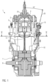
- the drawing shows a cross-sectional view along the line II 2 by a two-cycle engine 1 according to an embodiment according to the present invention.
- the two-stroke internal combustion engine or engine 1 has a combustion chamber 2 formed in a cylinder 3 above a piston 4 coupled via a connecting rod 5 to a crankshaft 6 rotatably housed in a crankcase 7 .
- the cylinder 3 is provided with an example based on 2 visible outlet 8 provided, can be disposed of via the exhaust gas. Further details of the engine 1, such as a clutch and an alternator and engine housing cover and the like have not been shown to simplify the drawing, but are of course present in an operational, ready-to-install engine 1.
- the cylinder 3 has two first transfer channels 9 and two second transfer channels 10, the first transfer channels 9 being arranged closer in the direction of the outlet 8 than the two second transfer channels 10.
- the overflow channels 9, 10 are flow-connected to the crank chamber formed inside the crankcase 7, so that when the piston 4 moves downwards in the direction of the crank chamber or the crankcase 7, compressed air or a compressed fuel-air mixture flows out of the crankcase 7 in the direction of the combustion chamber 2 can flow and can enter the combustion chamber 2 via the overflow window 11 from the overflow channels 9, 10.
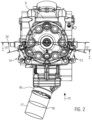
- the engine 1 has a first injector 13 and a second injector 14 , the first injector 13 pointing in the direction of the arrow 15 2 Viewed into the second overflow channel 10 on the right and the second injector 14 opens into the second overflow channel 10 on the left.
- the cylinder 3 therefore has two injectors 13, 14, each of which is designed to inject fuel into the respective transfer channel 10, specifically counter to the direction of flow of fluid from the crankcase 7 via the transfer channel 10 in the direction of the combustion chamber 2.
- the fuel is thereby set by a fuel pump, not shown, under a system pressure of, for example, 3.5 bar.
- the internal combustion engine 1 can be operated in different load ranges, with the load ranges extending from low loads in the idling range through medium loads to full load.
- the drawing shows that the engine has an intake manifold 16 in the intake area, on which a throttle valve body 17, shown schematically, is arranged with a throttle valve 18 that can be pivoted to change the flow cross section through the throttle valve body 17
- Two-stroke internal combustion engine 1 can represent.
- the throttle valve 18 is accommodated in a housing 19 of the throttle valve body 17 such that it can pivot, so that the user can pivot the throttle valve 18 in the direction of the arrow 20 8 can change the flow cross section released by the throttle valve 18 .
- the throttle body 17 has an idle system that is not shown in more detail, an in 8 Schematically illustrated rotational angle sensor 34 determined throttle valve angle of 0 degrees correspond to the idle position, while a throttle valve angle of 72 degrees with the reference numeral 18 'in 8 shown full load position corresponds.
- the internal combustion engine 1 is characterized in that at a first engine load, which is lower than a second engine load, the fuel is injected into the transfer channel 10 by means of only one injector 13, 14, while at the second engine load the fuel is injected by means of both injectors 13 , 14 is injected into the overflow channels 10.
- the fuel is injected with only one injector 13 or 14 into the overflow channel 10 and if the engine load increases, the operating mode of fuel injection with both injectors 13, 14 switched. If the engine load produced by the engine falls again, it is possible to switch back from the fuel injection operating mode with both injectors to the fuel injection operating mode with only one injector.
- the engine load can be done by detecting the crankcase pressure prevailing in the crankcase 7, which is controlled by the user of the engine 1 by means a change in the throttle valve angle depends on the load demand placed on the engine, so that the switchover between fuel delivery with just one injector or with both injectors takes place depending on the crankcase pressure.
- the fuel can be supplied alternately by one of the injectors 13, 14, so that in a cycle of 360 degrees crankshaft angle, the fuel is injected, for example, by the injector 13, while in the following Cycle of 360 degrees crankshaft angle the fuel from the other injector 14 is injected.
- This procedure has the advantage that the formation of gumming or coking on the injectors 13, 14 can be prevented and that, in addition, the switching cycles of the injectors 13, 14 are each distributed equally to about 50 percent.
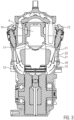
- the injector 13 like the injector 14, forms a spray cone 21 as a spray pattern, and the injectors are arranged in such a way that the spray cone 21 runs in the opposite direction to the fluid flow flowing in the overflow channel 10 in the direction of the overflow window 11 and thus the risk of wall deposits of the fuel discharged with the spray cone 21 on the wall 22 of the overflow channel 10 is reduced.
- Good fuel processing is also achieved due to the high turbulence prevailing in the overflow channel 10, with the result that the HC emissions in the exhaust gas are reduced.
- FIG. 5 The drawing shows the spray cone 21 in its formation in the overflow channel 10 at a distance from the wall 22 of the overflow channel 10.
- the fuel is injected into the overflow channels 10 and 10 spaced apart from the outlet 8 not in the overflow channels 9 which are closer to the outlet 8 and which also have a fluid connection to the crank chamber of the crankcase 7 .
- the formation of a short-circuit flow of fuel in the direction of the outlet 8 is reduced, as a result of which the scavenging losses of the two-stroke internal combustion engine 1 according to the invention are reduced.
- This can also reduce the specific fuel consumption of the engine and reduce the HC emissions that would otherwise occur when fuel is injected near the outlet and the resulting wall wetting of the cylinder wall in the area of the outlet 8 occurs.
- the injectors 13, 14 are both to the from 1 visible cylinder vertical axis 23 as well as to the basis of 2 apparent transverse center plane 24 arranged inclined.
- the injector 13, 14 is inclined with its injector vertical axis 25 at an angle of 14 degrees relative to the cylinder vertical axis 23.
- this configuration leads to the formation of a spray cone 21, which avoids wetting of the wall 22 of the overflow channel 10, in conjunction with the arrangement of the injector vertical axis 25 relative to the transverse center plane 24 of 15 degrees, as is illustrated in FIG 2 can be seen in the drawing.
- the injector 13 or 14 arranged on the cylinder 3 can also form a spray pattern in the form of two spray cones 21 which prevent wetting of the wall 22 of the overflow channel 10 .
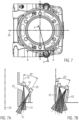
- FIG. 7 The drawing shows two sectional planes AA and BB to explain the angle of inclination that is formed between the cylinder vertical axis 23 and the injector vertical axis 25, and in Figure 7A is shown and to explain the angle that the injector vertical axis 25 relative to the longitudinal center plane 26 after 7 trains, and the in Figure 7B is shown.
- the injector 13, 14 can be arranged with its injector vertical axis 25 inclined at an angle of largely 0 degrees to about 35 degrees relative to the cylinder vertical axis 23, so that the spray cone 21 does not hit the wall 22 of the overflow channel 10.
- FIG. 7B The drawing shows the possible arrangement of the injectors 13, 14 relative to a cylinder vertical axis 23 receiving longitudinal center plane 26, which is based on 7 is evident.
- the injectors can be positioned at an angle of minus 8 degrees to the longitudinal median plane 26 - starting from a through the in Figure 7B left-side injector drawn virtual longitudinal center plane with 0 degrees -, and starting from this angle cover an angular range of 33 degrees without wall deposits of the injected fuel occurring on the wall 22 of the overflow channel 10.
- the two-stroke internal combustion engine 1 is also characterized in that the fuel can be injected via a single injector or both injectors during a partial range of a complete revolution of the crankshaft 6 corresponding to 360 degrees crankshaft angle, depending on the load state of the engine and the speed of the motor.
- the invention thus takes into account a peculiarity of two-stroke engines, which is characterized by the fact that the engine requires little fuel in the idling range, i.e. with a throttle valve opening angle of largely 0 degrees, and indeed over the entire speed range of the engine shown - with a displacement of 250 cubic centimeters - 1000 rpm to 11000 rpm.
- This entire speed range can be covered with the supply of fuel by means of only one injector 13, 14, even if the minimum injector opening time is not reached as the speed increases.
- a two-stroke internal combustion engine with a displacement of 250 cubic centimeters was mentioned here, it is also possible for the two-stroke internal combustion engine to have a displacement of 125, 150 or even 300 cubic centimeters.
- the engine according to the invention is designed in such a way that the fuel supply is switched over from one injector to both injectors in a load range from approximately 7 percent to approximately 40 percent of the maximum load, depending on the speed of the engine.
- the switchover from fuel supply using one injector to fuel supply using both injectors takes place at a lower load of, for example, 7 percent of the engine’s maximum load, while at low engine speeds the switchover only occurs at 40 percent of the maximum load takes place. If the engine falls below the value of 40 percent of the maximum load coming from a higher load at low engine speeds, the fuel supply switches from two injectors to just one injector, while at high engine speeds the fuel supply switches from both injectors to just one injector only at one engine load of about 7 percent of the maximum load takes place.
- the sub-range of the fuel supply referred to above in relation to the crankshaft angle of 360 degrees can range from about 5 degrees crank angle to about 350 degrees crank angle, the sub-range in the engine 1 shown in the drawing having a value of about 12 degrees crankshaft angle to about 305 degrees crankshaft angle occupies, so that at a throttle valve angle of 0 degrees, the supply of fuel by means of only one injector is sufficient during a crankshaft angle of around 12 degrees, while at a throttle valve angle of, for example, 72 degrees, which corresponds to the full load position of the engine, the sub-range of fuel supply by means of both injectors up to about 305 degrees of crankshaft angle, so fuel is introduced with both injectors during a very large sub-range of the maximum possible crankshaft angle, so it is possible to work with injectors that provide a relatively low specific mass throughput of fuel per second of, for example, 2.5 g/s , i.e. enter comparatively little fuel per unit of time.
- This configuration makes it possible for the engine to be operated even at high loads and high speeds by having a sufficient reserve of fuel in the crankcase, since the fuel is not only supplied during the opening period of the transfer windows, but is also introduced via the transfer channels then. when the transfer windows are closed by the piston.
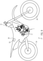
- the drawing shows a schematic representation of a motorcycle 27 which is equipped with the two-stroke internal combustion engine 1 according to the invention.
- the motorcycle 27 has a front wheel 28 and a rear wheel 29 and a seat for the user of the motorcycle in the form of a saddle 30.
- a user sitting on the saddle 30 or the seat 30 can control the motorcycle via the handlebar 31 and thereby via the Throttle twist grip 32 by means of a cable pull or also by means of drive-by-wire influence the angular position of the throttle valve 18 arranged in the throttle valve body 17 and thus control the engine load of the engine 1 .
- a throttle valve angle of largely 0 degrees is set and the engine is operated via the idling system of the throttle valve body 17 and a control device 33 functionally coupled to the internal combustion engine 1, which in the motorcycle 27 shown is below the Bench seat 30 is arranged, controls the injectors 13, 14 in such a way that they provide the fuel required for the operation of the engine 1 at idle by injecting it into the overflow channels 10 in an alternating manner.
- the control device 33 calculates the amount of fuel required for the throttle valve angle and meters it in by means of an injector 13, 14 or by means of both injectors 13, 14, in that the fuel is injected into the overflow channels 10, either in an alternating manner through one of the two injectors or through both injectors at the same time, so that the required amount of fuel is set.
- the engine load changes as a function of the throttle flap angle, which is determined by the angle of rotation sensor 34 and the fuel quantity corresponding to the engine load or the load requirement is determined via the control device 33 and the opening duration of the injector 13, 14 or the injectors 13, 14 is determined, which then Corresponds to the crankshaft angle, which corresponds to a partial range of the crankshaft angle corresponding to a complete revolution of the crankshaft.
Landscapes
- Engineering & Computer Science (AREA)
- Mechanical Engineering (AREA)
- Chemical & Material Sciences (AREA)
- Combustion & Propulsion (AREA)
- General Engineering & Computer Science (AREA)
- Fuel-Injection Apparatus (AREA)
- Electrical Control Of Air Or Fuel Supplied To Internal-Combustion Engine (AREA)
Description
- Die vorliegende Erfindung betrifft eine Zweitaktbrennkraftmaschine nach dem Oberbegriff des Anspruchs 1.
- Zweitaktbrennkraftmaschinen sind seit langer Zeit bekannt und werden auch zur Vermeidung von durch Spülverlusten entstehender HC Emissionen im Abgas einer entsprechenden Weiterentwicklung unterzogen, auch wenn die Zweitaktbrennkraftmaschine oder der Zweitaktmotor in vielen Bereichen mittlerweile vom Viertaktmotor verdrängt wurde. Aufgrund seiner hohen Leistungsdichte ist die Zweitaktbrennkraftmaschine aber nach wie vor technologisch sehr interessant und zwar insbesondere in den Bereichen, bei denen es auf eine hohe Leistungsausbeute bei geringer Masse ankommt, also beispielsweise im Bereich der Antriebsquelle von Motorrädern und hier insbesondere im Bereich von Geländesportmotorrädern, die hier aber lediglich als Beispiel genannt sind.
- Anhand der
US 7,16 8,401 B2 ist eine Zweitaktbrennkraftmaschine bekannt geworden, welche zur Kraftstoffversorgung des Zylinders der Motors zwei Injektoren aufweist, von denen ein erster Injektor Kraftstoff direkt in den Brennraum einspritzen kann und der andere Injektor Kraftstoff in den Überströmkanal einspritzen kann und zwar in Richtung der aus dem Kurbelgehäuse des Motors durch den Überströmkanal in Richtung zum Brennraum strömenden Fluidströmung. Es bedeutet dies mit anderen Worten, dass der Kraftstoff in den Überströmkanal in Strömungsrichtung eingespritzt wird. - Anhand der
DE 10 2004 002 161 B4 ist eine Zweitaktbrennkraftmaschine bekannt geworden, bei der ein Gemisch aus Kraftstoff und Schmieröl über ein Einspritzelement eingespritzt wird, welches mindestens zwei Einspritzstrahlen ausbildet, von denen ein erster Einspritzstrahl in den Überströmkanal in Strömungsrichtung aus dem Kurbelhaus in Richtung zum Brennraum und ein zweiter Einspritzstrahl in Richtung zur Kurbelkammer gerichtet wird. - Anhand der
DE 102 29 365 B4 ist ein Zweitaktmotor bekannt geworden, bei dem der Kraftstoff über einen Injektor in einen Überströmkanal eingespritzt wird und zwar in den Bereich unterhalb eines Einlassfensters oder auch auf der Höhe des Einlassfensters oder Überströmfensters. - Anhand der
EP 0 302 045 B2 ist eine Zweitaktbrennkraftmaschine bekannt geworden, bei der der Kraftstoff mittels zweier Einspritzdüsen auf den Kolbenboden und bei hohen Drehzahlen in den Überströmkanal eingespritzt wird. - Anhand der
DE 10 2008 019 157 A1 ist eine Zweitaktbrennkraftmaschine bekannt geworden, bei der der Kraftstoff entgegen der Strömungsrichtung aus dem Kurbelgehäuse in den Brennraum in den Überströmkanal eingespritzt wird. - Anhand der
US 7,08 9,892 B1 ist ein Fahrzeug mit einem Zweitaktmotor bekannt geworden, bei dem der Kraftstoff über einen ersten Injektor in das Kurbelgehäuse und über einen zweiten Injektor in den Überströmkanal eingetragen werden kann und zwar in einem nach oben gerichteten Winkel, also in Strömungsrichtung aus dem Kurbelgehäuse in den Brennraum der Brennkraftmaschine betrachtet, also nicht entgegen der Strömungsrichtung aus dem Kurbelgehäuse in den Brennraum. - Anhand der
DE 102 20 555 B4 ist ein Zweitaktmotor bekannt geworden, bei dem der Kraftstoff im Leerlauf in das Kurbelgehäuse und zu vorgegebenen Steuerzeiten in den Überströmkanal eingespritzt wird und zwar in das dem Brennraum zugewandte Ende des Überströmkanals, also quer zur Überströmrichtung. - Anhand der
US 6,691,649 B2 ist eine Zweitaktbrennkraftmaschine bekannt geworden, die mit zwei Injektoren pro Zylinder arbeitet und bei der der Kraftstoff in den Überströmkanal eingespritzt wird und zwar im Bereich des Einlassfensters aus dem Überströmkanal zum Zylinder und zwar in den Luftstrom, der vom Überströmkanal in den Zylinder strömt. - Schließlich ist anhand der
WO 2006/007614 A1 ein Zweitakt-Verbrennungsmotor bekannt geworden, bei der der Kraftstoff in den Überströmkanal eingespritzt wird und zwar weitgehend entgegen der Überströmrichtung aus dem Kurbelgehäuse in den Brennraum und bei der es also zu einer Gemischbildung außerhalb des Kurbelgehäuses des Zylinders kommt. - Eine Zweitaktbrennkraftmaschine zeichnet sich durch eine hohe Leistungsdichte aus und besitzt in Sachen des zur Erbringung der hohen Leistungsdichte benötigten Kraftstoffs eine hohe Spreizung, benötigt also im Bereich niedriger Drehzahlen und niedriger Last wenig Kraftstoff, während er im Bereich hoher Drehzahlen hoher Lasten einen hohen Kraftstoffbedarf aufweist.
- Dieses Problemfeld wurde bei den bekannten Zweitaktbrennkraftmaschinen allenfalls am Rande dadurch zu lösen versucht, dass bei hohem Kraftstoffbedarf der Kraftstoff entweder in dem Brennraum direkt eingespritzt wird oder in den Bereich des Überströmkanals, der über das Überströmfenster direkt mit dem Brennraum verbunden ist. Im erstgenannten Fall wird der Kraftstoff direkt in den Brennraum eingetragen und im zweitgenannten Fall weitgehend direkt über das Überströmfenster in den Brennraum, sodass es zu Zonen mit hoher Kraftstoff-Luftkonzentration kommt, was zwar einerseits der Entflammbarkeit des Gemisches entgegenkommt, andererseits aber die Gefahr von hohen HC Konzentrationen im Abgas des Motors erhöht.
- Wird darüber hinaus der Kraftstoff aufgrund der nur sehr kurzen Zeit der Öffnung des Überströmfensters mit hohen Einspritzdrücken in dem Brennraum eingebracht, so besteht die Gefahr, dass es zu Wandablagerungen des eingespritzten Kraftstoffs an der dem Überströmfenster gegenüberliegenden Zylinderwand im Brennraum kommt, was einerseits die Gefahr des Abwaschens des zum Betrieb des Zweitaktmotors benötigten Zweitaktöls von der Brennraumwand erhöht - und damit die Gefahr von Kolbenklemmern erhöht - und andererseits aufgrund der Wandablagerungen des Kraftstoffs an der Brennraumwand die HC Emissionen im Abgas wieder erhöht. Auch bei der Direkteinspritzung des Kraftstoffs in den Brennraum liegen diese Gefahren vor.
- Ausgehend hiervon liegt der vorliegenden Erfindung die Aufgabe zu Grunde, einen Zweitaktmotor zu schaffen, der die vorstehend genannten Probleme beseitigt und sich durch einen einfachen Aufbau auszeichnet und Zweitakt-typische Spülverluste vermeidet und zur Realisierung einer hohen Leistungsausbeute über den gesamten Last- und Drehzahlbereich bedarfsgerecht mit Kraftstoff versorgt werden kann.
- Die Erfindung weist zur Lösung dieser Aufgabe die im Anspruch 1 angegebenen Merkmale auf, vorteilhafte Ausgestaltungen hiervon sind in den weiteren Ansprüchen beschrieben. Auch schafft die Erfindung ein Verfahren zum Betrieb einer Zweitaktbrennkraftmaschine nach dem Anspruch 14 und ein Motorrad mit einer Zweittaktbrennkraftmaschine nach der Erfindung.
- Die Erfindung schafft eine Zweitaktbrennkraftmaschine mit mindestens einem, mit einem Brennraum und einem Auslass versehenen Zylinder und einem mit einer Kurbelwelle versehenen Kurbelgehäuse, welches über mindestens einen Überströmkanal mit dem Brennraum strömungsverbunden ist, wobei die Brennkraftmaschine zwei Injektoren aufweist und Kraftstoff mittels nur eines Injektors bei einer ersten Motorlast und mittels beider Injektoren bei einer zweiten Motorlast einbringbar ist, wobei die Brennkraftmaschine zwei Überströmkanäle pro Zyinder aufweist, wobei der jeweilige Überstömkanal mit einem jeweiligen Injektor versehen ist und die Brennkraftmaschine zum Einspritzen von Kraftstoff in den Überströmkanal weitgehend entgegen der Überströmrichtung aus dem Kurbelgehäuse in den Brennraum ausgebildet ist.
- Bei der Zweitaktbrennkraftmaschine wird also der Kraftstoff über den oder die beiden Injektoren nicht direkt in den Brennraum eingespritzt, sodass die Problematik des Abwaschens von Schmieröl von der Brennraumwand vermieden ist und es auch nicht zur Wandablagerung von Kraftstoff an der Brennraumwand kommen kann.
- Durch das Einspritzen von Kraftstoff in den Überströmkanal oder Überströmer durch beide Injektoren in getrennte Überströmkanäle entgegen der Überströmrichtung aus dem Kurbelgehäuse in Richtung zum Zylinderinnenraum wird eine sehr gute Kraftstoffaufbereitung durch hohe Turbulenzen im Überströmer erreicht, wodurch der Bildung von unverbrannten Kohlenwasserstoffen (HC Emissionen) im Abgas entgegengewirkt werden kann.
- Durch den Eintrag von Kraftstoff in den Überströmer mittels nur eines Injektors wird erreicht, dass einer niedrigen Kraftstoffanforderung des erfindungsgemäßen Zweitaktmotors Rechnung getragen wird, beispielsweise beim Leerlauf oder im niedrigen Lastbereich, nämlich dann, wenn der Zweitaktmotor wenig Kraftstoff benötigt. Dieser Betriebsbereich entspricht dem Betrieb des erfindungsgemäßen Zweitaktmotors bei einer ersten Motorlast.
- Steigt hingegen der Kraftstoffbedarf des erfindungsgemäßen Zweitaktmotors aufgrund einer höheren Lastanforderung beispielsweise durch den Benutzer des mit dem erfindungsgemäßen Zweitaktmotor betriebenen Motorrads an, so wird der Betrieb des erfindungsgemäßen Zweitaktmotors auf die Kraftstoffeinspritzung mittels beider Injektoren pro Zylinder umgestellt, dieser Betriebsbereich entspricht dem Betrieb des erfindungsgemäßen Zweitaktmotors bei einer zweiten Motorlast, die höher ist als die erste Motorlast, bei der der Kraftstoff mittels nur eines Injektors in den Überströmer eingebracht wird.
- Durch die erfindungsgemäß vorgesehene Möglichkeit, in den oder die Überströmer Kraftstoff in Abhängigkeit von der Motorlast einzutragen, wird der vorstehend erwähnten Zweitakt-spezifischen hohen Spreizung Rechnung getragen. Die Motorlast kann dabei die Sollmotorlast sein, die Motorlast also, die nach dem Wunsch des Benutzers des erfindungsgemäßen Motors vom Motor bereit gestellt werden soll, also die Arbeit die der Motor pro Arbeitsspiel leisten soll, bezogen auf das Hubvolumen eines Zylinders des Motors.
- Der Benutzer des Motors nimmt auf die vom Motor zu erbringende Motorlast durch einen Drosselöffnungsquerschnitt im Ansaugluftbereich des Motors Einfluss. Der Drosselöffnungsquerschnitt wird von der Öffnung eines Drosselorgans im Ansaugluftbereich des Motors bestimmt, wobei es sich bei dem Drosselorgan im einfachsten Fall um einen Luftschieber handeln kann, mit dessen Verlagerung der Öffnungsquerschnitt des Drosselorgans verändert wird, es kann sich auch um eine Drosselklappe handeln, deren Verschwenkung um einen Drosselklappenwinkel zu einer Veränderung des Öffnungsquerschnitts des Drosselorgans führt.
- Ein erster Drosselöffnungsquerschnitt kann also einer ersten Motorlast entsprechen, während ein zweiter Drosselöffnungsquerschnitt einer zweiten Motorlast entsprechen kann. Der Drosselöffnungsquerschnitt führt zu einer Veränderung des in der Kurbelkammer des Kurbelgehäuses festzustellenden Kurbelgehäusedrucks. Über die Erfassung des Kurbelgehäusedrucks kann die Umschaltung der Betriebsweise der erfindungsgemäßen Brennkraftmaschine mit einem Injektor oder mit zwei Injektoren pro Zylinder erfolgen. Ein erster Kurbelgehäusedruck, der einem ersten Drosselöffnungsquerschnitt und damit einer ersten Motorlast entspricht, führt dazu, dass dem erfindungsgemäßen Motor der Kraftstoff nur mittels Einspritzens von Kraftstoff in einen Überströmer zugeführt wird, während ein zweiter Kurbelgehäusedruck, der einem zweiten Drosselöffnungsquerschnitt und damit einer zweiten Motorlast entspricht, führt dazu, dass dem erfindungsgemäßen Motor der Kraftstoff mittels Einspritzens von Kraftstoff aus zwei Injektoren in zwei Überströmer oder in einen gemeinsamen Überströmer für beide Injektoren zugeführt wird.
- Durch das Umschalten der Betriebsweise der erfindungsgemäßen Brennkraftmaschine von der Kraftstoffversorgung mit nur einem Injektor auf die Kraftstoffversorgung mit beiden Injektoren und von der Kraftstoffversorgung mit beiden Injektoren auf die Kraftstoffversorgung mit nur einem Injektor kann den spezifischen Kraftstoffanforderungen der erfindungsgemäßen Brennkraftmaschine in Abhängigkeit von der Last des Motors Rechnung getragen werden.
- Es ist nach einer Weiterbildung der Erfindung auch vorgesehen, dass die Brennkraftmaschine zum alternierenden Einspritzen von Kraftstoff mittels eines der beiden Injektoren ausgebildet ist. Es bedeutet dies mit anderen Worten, dass dann, wenn zur Versorgung des erfindungsgemäßen Zweitaktmotors mit der im jeweiligen Betriebspunkt benötigten Kraftstoffmenge die Kraftstoffmenge nur mit einem Injektor zugeführt wird, der Kraftstoff beispielsweise im Verlauf einer Kurbelwellenumdrehung von einem Injektor zugeführt wird und im Verlauf der nächsten Kurbelwellenumdrehung vom anderen Injektor zugeführt wird, die beiden Injektoren also beispielsweise pro Kurbelwellenumdrehung alternierend zur Kraftstoffzufuhr eingesetzt werden. Es ist auch möglich, dass der Kraftstoff beispielsweise während einer vorbestimmten Zahl von Kurbelwellenumdrehungen mittels des einen Injektors zugeführt wird und der Kraftstoff während einer darauffolgenden Zahl von Kurbelwellenumdrehungen mittels des anderen Injektors zugeführt wird.
- Diese Vorgehensweise hat den Vorteil, dass bei einer kleinen Motorlast eine optimierte Kraftstoffmengenbemessung erreicht wird und dass Verschmutzungen eines ansonsten für eine längere Zeitdauer nicht von Kraftstoff durchströmten Injektors vorgebeugt werden kann. Solche Verschmutzungen können beispielsweise die Folge von Abgas im Kurbelhaus aufgrund von blow-by Effekten sein oder auch die Folge von für den Betrieb des Zweitaktmotors benötigten Schmieröls, welches in das Kurbelgehäuse eingetragen wird. Durch die alternierende Benutzung beider Injektoren auch bei der Zufuhr von Kraftstoff mittels nur eines Injektors kann solchen Verschmutzungen vorgebeugt werden. Auch kann etwaigen Verharzungen oder Verklebungen der Injektoren durch im Kraftstoff vorhandene Additive oder Bestandteile auf diese Weise vorgebeugt werden und es kann einer ansonsten Ungleichverteilung der mechanischen Belastung der beiden Injektoren vorgebeugt werden.
- Es ist nach einer Weiterbildung der Erfindung auch vorgesehen, dass die Brennkraftmaschine zum Einspritzen von Kraftstoff während eines Kurbelwellenwinkels ausgebildet ist, der einem Teilbereich einer vollständigen Umdrehung der Kurbelwelle entspricht und der Teilbereich etwa 5 Grad Kurbelwellenwinkel bis etwa 350 Grad Kurbelwellenwinkel, vorzugsweise etwa 10 Grad Kurbelwellenwinkel bis etwa 330 Grad Kurbelwellenwinkel, vorzugsweise etwa 12 Grad Kurbelwellenwinkel bis etwa 305 Grad Kurbelwellenwinkel beträgt.
- Es bedeutet dies mit anderen Worten, dass die erfindungsgemäße Brennkraftmaschine so ausgebildet ist, dass der Kraftstoff während eines Teilbereichs einer vollständigen Umdrehung der Kurbelwelle von 360 Grad Kurbelwinkel eingespritzt wird und dieser Teilbereich von einem sehr kurzen Zeitfenster von etwa nur 5 Grad Kurbelwellenwinkel bis zu einem sehr langen Zeitfenster von 350 Grad Kurbelwinkel reicht. Kraftstoff also nur während eines sehr kurzen Einspritzzeitintervalls einer vollständigen Kurbelwellenumdrehung eingespritzt wird oder auch während eines Zeitintervall, welches nahezu einer vollständigen Umdrehung der Kurbelwelle entspricht und somit Kraftstoff fast während der gesamten Zeitdauer einer vollständigen Kurbelwellenumdrehung eingespritzt wird, wodurch Kraftstoff in der Kurbelkammer des Kurbelgehäuses auch vorgelagert werden kann.
- Es ist nach der Erfindung auch vorgesehen, dass das Einspritzintervall von etwa 10 Grad Kurbelwinkel bis etwa 330 Grad Kurbelwinkel reicht und es hat sich gezeigt, dass bei einer Zweitaktbrennkraftmaschine mit einem Hubvolumen von 250 cm3 sehr gute Ergebnisse erzielt werden bei einem Einspritzintervall von etwa 12 Grad Kurbelwinkel bis etwa 305 Grad Kurbelwinkel.
- Es ist nach einer Weiterbildung der Erfindung auch vorgesehen, dass die Zweitaktbrennkraftmaschine zum Einspritzen von Kraftstoff mittels nur eines Injektors in einem Bereich der Motorlast der Brennkraftmaschine von etwa sieben Prozent bis etwa 40 Prozent der Maximallast der Brennkraftmaschine ausgebildet ist, wobei sich der Wert in Abhängigkeit der Motordrehzahl ändert. Der Benutzer des erfindungsgemäßen Motors kann die an den Motor gestellte Lastanforderung durch eine Veränderung des Drosselöffnungsquerschnitts eines im Ansaugluftbereich des Motors angeordneten Drosselorgans beeinflussen, sodass beispielsweise bei einer Lastanforderung von mehr als etwa 40 Prozent der Maximallast Kraftstoff mittels beider Injektoren eingespritzt wird, während bei einer Lastanforderung von weniger als etwa 40 Prozent der Maximallast Kraftstoff nur mittels eines Injektors eingespritzt wird und zwar in Abhängigkeit der jeweiligen Motordrehzahl. Wie vorstehend bereits erwähnt, kann der Kraftstoff dann im alternierenden Betrieb durch jeweils einen der beiden Injektoren eingespritzt werden. Das Umschalten vom Betrieb mit einem Injektor auf den Betrieb mit zwei Injektoren und umgekehrt erfolgt also im Bereich von etwa 7 Prozent bis etwa 40 Prozent der Last.
- Die Abhängigkeit der Motordrehzahl bedeutet dabei, dass der Umschaltzeitpunkt vom Betrieb der erfindungsgemäßen Zweitaktbrennkraftmaschine mit nur einem Injektor auf den Betrieb mit beiden Injektoren pro Zylinder und das Umschalten vom Betrieb mit beiden Injektoren auf den Betrieb mit nur einem Injektor - die dann alternierend betrieben werden können - von der Motordrehzahl abhängt.
- Bei niedrigen Motordrehzahlen kann also ein Injektor bis zu einer Last von etwa 40 Prozent der Maximallast des Motors reichen, während bei hohen Motordrehzahlen bereits ab einer Motorlast von etwa 7 Prozent der Maximallast auf den Betrieb mit zwei Injektoren umgeschaltet wird und der Motor im Falle einer Lastanforderung von unter 7 Prozent der Maximallast weiterhin mit nur einem Injektor betrieben werden kann.
- Es ist nach einer Weiterbildung der Erfindung auch vorgesehen, dass die Brennkraftmaschine nach der Erfindung zum Einspritzen von Kraftstoff während eines mit steigender Drehzahl der Brennkraftmaschine zunehmenden Teilbereichs des einer vollständigen Umdrehung der Kurbelwelle entsprechenden Kurbelwellenwinkels ausgebildet ist.
- Es bedeutet dies mit anderen Worten, dass das Zeitintervall, während dessen Kraftstoff mittels eines Injektors oder auch mittels beider Injektoren in den oder die Überströmkanäle eingespritzt wird, mit zunehmender Drehzahl der erfindungsgemäßen Brennkraftmaschine länger wird, also während eines größeren Teilbereichs einer vollständigen Kurbelwellenumdrehung von 360 Grad Kraftstoff mit einem Injektor oder auch mit beiden Injektoren eingespritzt wird, wodurch für den Betrieb der Brennkraftmaschine in Abhängigkeit der Motordrehzahl Kraftstoff auch im Kurbelgehäuse vorgelagert werden kann, Kraftstoff also auch dann in den oder die Überströmkanäle eingespritzt wird, wenn das Überströmfenster vom Überströmkanal in den Brennraum des Zylinders durch den sich im Zylinder zwischen dem unteren Totpunkt UT und oberen Totpunkt OT bewegenden Kolben verschlossen ist.
- Es ist nach einer Weiterbildung der Erfindung auch vorgesehen, dass die Brennkraftmaschine mit einer Steuereinrichtung funktional gekoppelt oder auch versehen ist und die Steuereinrichtung zur Feststellung einer Lastanforderung an die Brennkraftmaschine ausgebildet ist und das Einspritzen von Kraftstoff mittels eines Injektors oder beider Injektoren in Abhängigkeit von der festgestellten Lastanforderung erfolgt. Über die Steuereinrichtung kann daher die vom Benutzer angeforderte Sollmotorlast oder Zielmotorlast festgestellt werden, beispielsweise über die Erfassung eines Drosselöffnungsquerschnitts eines dem Motor zur Zuführung von Ansaugluft strömungstechnisch vorgeschalteten Drosselorgans, bei dem es sich um einen Vergaser oder auch eine Drosselklappe handeln kann, und in Abhängigkeit von der festgestellten Motorlast wird dann von der Steuereinrichtung entweder ein Injektor oder beide Injektoren zur Abgabe von Kraftstoff in den Überströmkanal oder die Überströmkanäle betätigt.
- Es ist nach einer Weiterbildung der Erfindung auch vorgesehen, dass die Brennkraftmaschine zur Veränderung des Beginns des Einspritzens von Kraftstoff mittels eines Injektors oder beider Injektoren und/oder der Zeitdauer der Öffnungsbetätigung des Injektors oder beider Injektoren in Abhängigkeit von der festgestellten Lastanforderung und/oder der Drehzahl der Brennkraftmaschine ausgebildet ist.
- Die Brennkraftmaschine kann daher die Injektoren so betätigen, dass der Beginn des Einspritzens von Kraftstoff in den Überströmkanal oder die Überströmkanäle in Abhängigkeit von der Motorlast oder der festgestellten Lastanforderung und/oder der aktuellen Motordrehzahl der Brennkraftmaschine verändert wird. Auf der Basis der so festgestellten Betriebsparameter der erfindungsgemäßen Brennkraftmaschine kann diese also das Einspritzintervall, während dessen Kraftstoff in den Überströmkanal oder in die Überströmkanäle eingespritzt wird, innerhalb des zur Verfügung stehenden Intervalls von 360 Grad Kurbelwinkel verschieben und/oder verkürzen und/oder verlängern.
- Eine Verschiebung des Einspritzintervalls in Richtung früh bedeutet dabei, dass das Einspritzintervall in einen Bereich nach dem oberen Totpunkt OT des Kolbens auf seinem Weg in Richtung zum unteren Totpunkt UT des Kolbens nach oben verschoben wird, also in Richtung zum oberen Totpunkt OT hin, während eine Verschiebung des Einspritzintervalls in Richtung spät bedeutet, dass das Einspritzintervall in einen Bereich nach dem oberen Totpunkt OT des Kolbens auf seinem Weg in Richtung zum unteren Totpunkt UT des Kolbens nach unten verschoben wird, also in Richtung zum unteren Totpunkt UT hin.
- Es ist nach einer Weiterbildung der Erfindung auch vorgesehen, dass der Zylinder mit ersten und zweiten Überströmkanälen versehen ist und die zweiten Überströmkanäle relativ zum Auslass weiter beabstandet angeordnet sind als die ersten Überströmkanäle und die Injektoren zur Einspritzung von Kraftstoff in die zweiten Überströmkanäle angeordnet sind.
- Auf diese Weise wird es erreicht, dass die Spülverluste verringert werden, da das Entstehen von Kurzschlussströmungen zwischen den ersten Überströmkanälen und dem Auslass des Zylinders verringert oder vermieden wird. Die Gefahr solcher Kurzschlussströmungen würde steigen, wenn der Kraftstoff in die dem Auslass näher benachbarten Überströmkanäle eingespritzt werden würde. Dies trägt zur Verringerung der HC Emissionen im Abgas der erfindungsgemäßen Brennkraftmaschine bei.
- Es ist nach einer Weiterbildung der Erfindung auch vorgesehen, dass die Brennkraftmaschine eine von der Längsmittelachse des Zylinders gebildete Zylinderhochachse aufweist und jeder Injektor eine von der Längsmittelachse des Injektors gebildete Injektorhochachse aufweist und die Injektoren in einem Winkel zwischen der Zylinderhochachse und der Injektorhochachse von etwa Null Grad bis etwa 35 Grad, vorzugsweise etwa 14 Grad geneigt angeordnet sind.
- Auf diese Art und Weise wird es erreicht, dass die Gefahr von Wandanlagerungen von Kraftstoff an den Kanalwänden der Überströmkanäle verringert wird, was zur Verringerung von unverbrannten Kohlenwasserstoffen im Abgas der erfindungsgemäßen Brennkraftmaschine beiträgt.
- Es ist nach einer Weiterbildung der Erfindung auch vorgesehen, dass die Brennkraftmaschine eine die Zylinderhochachse einschließende Längsmittelebene - eine gedachte oder virtuelle Längsmittelebene - aufweist und eine zur Längsmittelebene im rechten Winkel stehende Quermittelebene - eine gedachte oder virtuelle Quermittelebene - aufweist und die Injektoren in eine Winkel zwischen der Längsmittelebene und der Injektorhochachse von etwa minus 8 Grad bis etwa plus 33 Grad geneigt angeordnet sind. Die Injektoren können dabei relativ zur Quermittelebene in Richtung vom Auslass weg um etwa 15 Grad nach hinten versetzt angeordnet sein.
- Auch diese Konfiguration weist den Vorteil auf, dass der von den Injektoren in der Form eines Strahlkegels oder Spritzkegels in den Überströmkanal oder die Überströmkanäle eingebrachte Kraftstoff wenig oder nicht mit den Wandungen des Überströmkanals oder der Überströmkanäle in Kontakt kommt, sondern vor einem solchen möglichen Kontakt von der im Überströmkanal oder den Überströmkanälen ausgehend von der Kurbelkammer in Richtung zur Brennkammer strömenden Fluidströmung aufgelöst und mitgerissen wird. Diese Konfiguration trägt wiederum dazu bei, dass die Bildung von unverbrannten Kohlenwasserstoffen im Abgas der erfindungsgemäßen Brennkraftmaschine verringert wird.
- Es ist nach einer Weiterbildung der Erfindung vorgesehen, dass die Injektoren ganz allgemein relativ zum jeweiligen Überströmkanal so angeordnet sind, dass Anlagerungen des vom Injektor in den Überströmkanal eingespritzten Kraftstoffs an der Wandung des Überströmkanals weitgehend vermieden sind. Diese Konfiguration besitzt wiederum den Vorteil, dass die Bildung von in Tropfenform vom Überstömkanal in den Brennraum gelangender Kraftstoffteilchen verringert oder vermieden wird, wodurch wieder die HC Emissionen im Abgas verringert werden können. Auch wird dadurch der spezifische Kraftstoffverbrauch der erfindungsgemäßen Zweitaktbrennkraftmaschine verringert.
- Schließlich ist es nach einer Weiterbildung der Erfindung auch vorgesehen, dass der Injektor mindestens einen kegelförmigen Kraftstoffstrahl erzeugt und der Injektor relativ zum Überströmkanal zur Vermeidung von Wandanlagerungen des Kraftstoffstrahls an der Wandung des Überströmkanals ausgerichtet ist.
- Die Erfindung schafft auch ein Verfahren zum Betrieb einer Zweitaktbrennkraftmaschine, die mindestens einen, mit einem Brennraum und einem Auslass versehenen Zylinder mit zwei Überströmkanälen und ein mit einer Kurbelwelle versehenes Kurbelgehäuse aufweist, welches über die Überströmkanale mit dem Brennraum strömungsverbunden ist, wobei das Verfahren die Zufuhr von Kraftstoff zur Zweitaktbrennkraftmaschine mittels zweier Injektoren umfasst und Kraftstoff mittels nur eines Injektors bei einer ersten Motorlast und mittels beider Injektoren bei einer zweiten Motorlast zugeführt wird, wobei der Kraftstoff in die Überströmkanäle weitgehend entgegen der Überströmrichtung aus dem Kurbelgehäuse in den Brennraum eingespritzt wird.
- Die erste Motorlast ist dabei niedriger als die zweite Motorlast, sodass in Abhängigkeit von der Motorlast, also der Last der Brennkraftmaschine oder auch einer durch die Feststellung eines Drosselöffnungsquerschnitts eines Drosselorgans, welches der erfindungsgemäßen Brennkraftmaschine strömungstechnisch vorgeschaltet ist, festgestellten Lastanforderung an die erfindungsgemäße Brennkraftmaschine der Kraftstoff in den Überströmkanal mittels nur eines Injektors eingespritzt wird oder der Kraftstoff in die Überströmkanäle mittels beider Injektoren eingespritzt wird.
- Der Betrieb der erfindungsgemäßen Brennkraftmaschine mit nur einem Injektor oder beiden Injektoren kann daher in Abhängigkeit von der Motorlast oder der festgestellten Lastanforderung hin- und her geschaltet werden, je nachdem, welche Motorlast vorliegt oder welche Lastanforderung an den Motor gestellt wird.
- Die Erfindung wird im folgenden anhand der Zeichnung näher erläutert. Diese zeigt in:
-
Fig. 1 eine Schnittsansicht einer Einzylinder-Zweitaktbrennkraftmaschine nach einer Ausführungsform gemäß der vorliegenden Erfindung in einer Querschnittsdarstellung gemäß der Linie I-I nachFigur 2 ; -
Fig. 2 eine Draufsichtansicht auf die Ausführungsform nachFig. 1 ; -
Fig. 3 eine Ansicht ähnlich derjenigen nachFig. 1 zur Erläuterung des Sprühbilds oder Strahlbilds eines Injektors; -
Fig. 4 eine Darstellung ähnlich derjenigen nachFig. 2 ohne den Zylinderkopf; -
Fig. 5 eine Schnittansicht entlang der Linie V-V nachFig. 1 ; -
Fig. 6 eine Schnittdarstellung entlang der Linie VI-VI nachFig. 5 ; -
Fig. 7 eine Draufsichtansicht auf den Zylinder der Zweitaktbrennkraftmaschine nachFig. 1 zur Erläuterung der Lage von zwei Schnittebenen A-A und B-B fürFig. 7A und Fig. 7B ; -
Fig. 7A , B Schnittdarstellungen entlang der Linie A-A und B-B nachFig. 7 ; -
Fig. 8 eine Schnittdarstellung durch einen schematisch dargestellten Drosselklappenkörper; und -
Fig. 9 eine schematische Darstellung eines Motorrads mit der erfindungsgemäßen Brennkraftmaschine. -
Fig. 1 der Zeichnung zeigt eine Querschnittsansicht entlang der Linie I-I nachFig. 2 durch eine Zweitaktbrennkraftmaschine 1 nach einer Ausführungsform gemäß der vorliegenden Erfindung. - Die Zweitaktbrennkraftmaschine oder der Motor 1 weist einen Brennraum 2 auf, der in einem Zylinder 3 oberhalb eines Kolbens 4 ausgebildet ist, der über eine Pleuelstange 5 mit der Kurbelwelle 6 gekoppelt ist, welche in einem Kurbelgehäuse 7 drehbar aufgenommen ist. Der Zylinder 3 ist mit einem beispielsweise anhand von
Fig. 2 ersichtlichen Auslass 8 versehen, über den Abgas entsorgt werden kann. Weitere Einzelheiten des Motors 1, wie beispielsweise eine Kupplung und eine Lichtmaschine und Motorgehäusedeckel und dergleichen sind der Vereinfachung der Zeichnung halber nicht dargestellt worden, bei einem betriebsbereit einbaufertigen Motor 1 selbstverständlich aber vorhanden. - Wie es beispielsweise anhand von
Fig. 5 der Zeichnung ersichtlich ist, weist der Zylinder 3 zwei erste Überströmkanäle 9 und zwei zweite Überströmkanäle 10 auf, wobei die ersten Überströmkanäle 9 näher in Richtung des Auslasses 8 angeordnet sind als die beiden zweiten Überströmkanäle 10. - Die Überströmkanäle 9, 10 sind mit der im Inneren des Kurbelgehäuses 7 ausgebildeten Kurbelkammer strömungsverbunden, sodass bei der Abwärtsbewegung des Kolbens 4 in Richtung zur Kurbelkammer bzw. dem Kurbelgehäuse 7 verdichtete Luft bzw. verdichtetes Kraftstoff-Luftgemisch aus dem Kurbelgehäuse 7 in Richtung zum Brennraum 2 strömen kann und über Überströmfenster 11 aus den Überströmkanälen 9, 10 in den Brennraum 2 eintreten kann.
- Bei der Abwärtsbewegung des Kolbens 4 in Richtung zum unteren Totpunkt UT kommt es daher zu einer Fluidströmung, welche durch die Pfeile 12 in
Fig. 3 der Zeichnung dargestellt ist. Es ist dabei zu beachten, dass inFig. 1 der Zeichnung lediglich der in der Zeichnungsebene rechte Überströmkanal 10 frei geschnitten dargestellt ist, während der in der Zeichnungsebene linke Überströmkanal 10 aufgrund des Schnittverlaufs nicht geschnitten dargestellt ist.Fig. 3 zeigt beide Überströmkanäle 10. - Wie es anhand von
Fig. 2 der Zeichnung ersichtlich ist, weist der Motor 1 einen ersten Injektor 13 und einen zweiten Injektor 14 auf, wobei der erste Injektor 13 in Richtung des Pfeils 15 nachFig. 2 betrachtet in den rechtsseitigen zweiten Überströmkanal 10 und der zweite Injektor 14 in den linksseitigen zweiten Überströmkanal 10 mündet. - Der Zylinder 3 weist also zwei Injektoren 13, 14 auf, die jeweils zum Einspritzen von Kraftstoff in den jeweiligen Überströmkanal 10 ausgebildet sind und zwar entgegen der Strömungsrichtung von Fluid aus dem Kurbelgehäuse 7 über den Überströmkanal 10 in Richtung zum Brennraum 2. Der Kraftstoff wird dabei von einer nicht näher dargestellten Kraftstoffpumpe unter einen Systemdruck von beispielsweise 3.5 bar gesetzt.
- Die Brennkraftmaschine 1 kann in unterschiedlichen Lastbereichen betrieben werden, wobei die Lastbereiche von niedrigen Lasten im Bereich des Leerlaufs über mittlere Lasten bis zur Volllast reichen.
-
Fig. 2 der Zeichnung zeigt, dass der Motor im Einlassbereich einen Ansaugstutzen 16 aufweist, an dem ein schematisch dargestellter Drosselklappenkörper 17 mit einer zur Veränderung des Durchflussquerschnitts durch den Drosselklappenkörper 17 verschwenkbaren Drosselklappe 18 angeordnet ist, über deren Verschwenkung ein Benutzer der erfindungsgemäßen Zweitaktbrennkraftmaschine 1 eine Lastanforderung an die Zweitaktbrennkraftmaschine 1 darstellen kann. - Die Drosselklappe 18 ist dabei in einem Gehäuse 19 des Drosselklappenkörpers 17 verschwenkbar aufgenommen, sodass der Benutzer über eine Verschwenkbewegung der Drosselklappe 18 in Richtung des Pfeils 20 nach
Fig. 8 den von der Drosselklappe 18 freigegebenen Durchflussquerschnitt verändern kann. Da der Drosselklappenkörper 17 ein nicht näher dargestelltes Leerlaufsystem aufweist, kann ein über einen inFig. 8 schematisch dargestellten Drehwinkelsensor 34 festgestellter Drosselklappenwinkel von 0 Grad der Leerlaufstellung entsprechen, während ein Drosselklappenwinkel von 72 Grad der mit dem Bezugszeichen 18' inFig. 8 dargestellten Volllaststellung entspricht. - Die erfindungsgemäße Brennkraftmaschine 1 zeichnet sich dadurch aus, dass bei einer ersten Motorlast, die niedriger ist als eine zweite Motorlast, der Kraftstoff mittels nur eines Injektors 13, 14 in den Überströmkanal 10 eingespritzt wird, während bei der zweiten Motorlast der Kraftstoff mittels beider Injektoren 13, 14 in die Überströmkanäle 10 eingespritzt wird.
- Es bedeutet dies mit anderen Worten, dass in Abhängigkeit von der Motorlast, mit der die Zweitaktbrennkraftmaschine 1 betrieben wird, der Kraftstoff entweder mittels nur eines Injektors 13 oder 14 in den Überstromkanal 10 eingebracht wird oder mittels beider Injektoren 13, 14 eingebracht wird, wobei zwischen den Betriebsmodi "nur ein Injektor" und "beide Injektoren" je nach Motorlast oder Lastanforderung umgeschaltet wird.
- Befindet sich der Motor in einem Betriebsmodus mit nur geringer Last, wird der Kraftstoff mit nur einem Injektor 13 oder 14 in den Überströmkanal 10 eingespritzt und steigt die Motorlast an, wird ab einem drehzahlabhängigen Schwellenwert der Last auf den Betriebsmodus der Kraftstoffeinspritzung mit beiden Injektoren 13, 14 umgeschaltet. Sinkt die vom Motor dargestellte Motorlast wieder ab, kann wieder vom Betriebsmodus der Kraftstoffeinspritzung mit beiden Injektoren auf den Betriebsmodus der Kraftstoffeinspritzung mit nur einem Injektor umgeschaltet werden.
- Die Motorlast kann dabei mittels einer Erfassung des im Kurbelgehäuse 7 herrschenden Kurbelgehäusedrucks erfolgen, der von der vom Benutzer des Motors 1 mittels einer Veränderung des Drosselklappenwinkels an den Motor gestellten Lastanforderung abhängt, sodass in Abhängigkeit von dem Kurbelgehäusedruck die Umschaltung zwischen der Kraftstoffzufuhr mit nur einem Injektor oder mit beiden Injektoren erfolgt.
- Wird zur Kraftstoffversorgung des Motors 1 nur ein Injektor 13, 14 benötigt, so kann die Kraftstoffzufuhr durch jeweils einen der Injektoren 13, 14 alternierend erfolgen, sodass also in einem Zyklus von 360 Grad Kurbelwellenwinkel der Kraftstoff beispielsweise vom Injektor 13 eingespritzt wird, während im nachfolgenden Zyklus von 360 Grad Kurbelwellenwinkel der Kraftstoff vom anderen Injektor 14 eingespritzt wird.
- Diese Vorgehensweise hat den Vorteil, dass der Bildung von Verharzungen oder Verkokungen an den Injektoren 13, 14 vorgebeugt werden kann und dass darüber hinaus die Schaltzyklen der Injektoren 13, 14 jeweils zu etwa 50 Prozent gleich verteilt werden.
- Wie es anhand von
Fig. 3 der Zeichnung ersichtlich ist, bildet der Injektor 13, genauso wie der Injektor 14, als Sprühbild einen Sprühkegel 21 aus, und die Injektoren sind so angeordnet, dass der Sprühkegel 21 der im Überströmkanal 10 in Richtung zum Überströmfenster 11 strömenden Fluidströmung entgegen gerichtet ausgerichtet verläuft und somit die Gefahr von Wandanlagerungen des mit dem Sprühkegel 21 ausgetragenen Kraftstoffs an der Wandung 22 des Überströmkanals 10 verringert ist. Auch wird durch die im Überströmkanal 10 herrschenden hohen Turbulenzen eine gute Kraftstoffaufbereitung erreicht, womit die HC Emissionen im Abgas verringert werden. -
Fig. 5 der Zeichnung zeigt den Sprühkegel 21 in seiner Ausbildung im Überströmkanal 10 im Abstand zur Wandung 22 des Überströmkanals 10. Die Kraftstoffeinspritzung erfolgt dabei in die vom Auslass 8 beabstandeten Überströmkanäle 10 und nicht in die näher zum Auslass 8 liegenden Überströmkanäle 9, welche ebenfalls eine Fluidverbindung zur Kurbelkammer des Kurbelgehäuses 7 besitzen. Durch die auslassferne Einbringung des Kraftstoffs in die Überströmkanäle 10 wird die Bildung einer Kurzschlussströmung von Kraftstoff in Richtung zum Auslass 8 hin verringert, wodurch die Spülverluste der erfindungsgemäßen Zweitaktbrennkraftmaschine 1 verringert werden. Auch kann dadurch der spezifische Kraftstoffverbrauch des Motors verringert werden und es können die HC Emissionen reduziert werden, die sich andernfalls beim auslassnahen Einspritzen von Kraftstoff und der daraus resultierenden Wandbenetzungen der Zylinderwand im Bereich des Auslasses 8 einstellen würden. -
Fig. 4 zeigt die Anordnung der Injektoren 13, 14 am Zylinder 3 in einer Ansicht von oben. Wie es ohne weiteres ersichtlich ist, sind die Injektoren 13, 14 sowohl zu der ausFig. 1 ersichtlichen Zylinderhochachse 23 als auch zu der anhand vonFig. 2 ersichtlichen Quermittelebene 24 geneigt angeordnet. - Bei der in
Fig. 1 der Zeichnung dargestellten Ausführungsform des Motors 1 ist der Injektor 13, 14 mit seiner Injektorhochachse 25 relativ zur Zylinderhochachse 23 in einem Winkel von 14 Grad geneigt. Diese Konfiguration führt bei dem dargestellten Motor 1 zu der eine Wandbenetzung der Wandung 22 des Überströmkanals 10 vermeidenden Ausbildung eines Sprühkegel 21 und zwar in Verbindung mit dem Anordnung der Injektorhochachse 25 relativ zur Quermittelebene 24 von 15 Grad, wie dies anhand vonFig. 2 der Zeichnung ersichtlich ist. - Wie es anhand von
Fig. 6 der Zeichnung ersichtlich ist, kann der am Zylinder 3 angeordnete Injektor 13 oder 14 auch ein Sprühbild in der Form von zwei Sprühkegeln 21 ausbilden, die eine Wandbenetzung der Wandung 22 des Überströmkanals 10 verhindern. -
Fig. 7 der Zeichnung zeigt zwei Schnittebenen A-A und B-B zur Erläuterung des Neigungswinkel, der zwischen der Zylinderhochachse 23 und der Injektorhochachse 25 ausgebildet wird, und der inFig. 7A dargestellt ist und zur Erläuterung des Winkels, den die Injektorhochachse 25 relativ zur Längsmittelebene 26 nachFig. 7 ausbildet, und der inFig. 7B dargestellt ist. - Wie es anhand von
Fig. 7A dargestellt ist, kann der Injektor 13, 14 mit seiner Injektorhochachse 25 in einem Winkel von weitgehend 0 Grad bis etwa 35 Grad relativ zur Zylinderhochachse 23 geneigt angeordnet werden, sodass der Sprühkegel 21 nicht auf die Wandung 22 des Überströmkanals 10 trifft. -
Fig. 7B der Zeichnung zeigt die mögliche Anordnung der Injektoren 13, 14 relativ zu einer die Zylinderhochachse 23 aufnehmenden Längsmittelebene 26, die anhand vonFig. 7 ersichtlich ist. Wie es ohne weiteres deutlich ist, können die Injektoren in einem Winkel von minus 8 Grad zur Längsmittelebene 26 angeordnet sein - ausgehend von einer durch den inFig. 7B linksseitigen Injektor gezogenen virtuellen Längsmittelebene mit 0 Grad -, und ausgehend von diesem Winkel einen Winkelbereich von 33 Grad überdecken, ohne dass es zu Wandanlagerungen des eingespritzten Kraftstoffs an der Wandung 22 des Überströmkanals 10 kommt. Dies gilt sowohl für die in der Zeichnung dargestellten Injektoren mit einem Sprühbild mit zwei Sprühkegeln als auch für Injektoren mit einem Sprühbild mit nur jeweils einem Sprühkegel ähnlich der Darstellung inFig. 7A . - Die erfindungsgemäße Zweitaktbrennkraftmaschine 1 zeichnet sich darüber hinaus dadurch aus, dass der Kraftstoff über einen einzelnen Injektor oder beide Injektoren während eines Teilbereichs einer vollständigen, 360 Grad Kurbelwellenwinkel entsprechenden Umdrehung der Kurbelwelle 6 eingespritzt werden kann, und zwar in Abhängigkeit vom Lastzustand des Motors und der Drehzahl des Motors.
- Damit trägt die Erfindung einer Eigenheit von Zweitaktmotoren Rechnung, die sich dadurch auszeichnet, dass der Motor im Leerlaufbereich, also bei einem Drosselklappenöffnungswinkel von weitgehend 0 Grad wenig Kraftstoff benötigt und zwar über den gesamte Drehzahlbereich vom beim dargestellten Motor - mit einem Hubvolumen von 250 Kubikzentimeter - 1000 Umdrehungen pro Minute bis 11000 Umdrehungen pro Minute. Dieser gesamte Drehzahlbereich kann mit der Zuführung von Kraftstoff mittels nur eines Injektors 13, 14 abgedeckt werden und zwar selbst dann, wenn dabei mit steigender Drehzahl die minimale Injektoröffnungszeit unterschritten wird. Obwohl hier eine Zweitaktbrennkraftmaschine von 250 Kubikzentimeter Hubraum genannt wurde, ist es auch möglich, dass die Zweitaktbrennkraftmaschine ein Hubvolumen von 125, 150 oder auch 300 Kubikzentimeter besitzt.
- Dies ist darauf zurückzuführen, dass der erfindungsgemäße Motor aufgrund der vorteilhaften Anordnung der Injektoren 13, 14 im Leerlaufbereich auch mit einem zudosierten Kraftstoff arbeitet, der sich der Menge nach dann einstellt, wenn der Injektor eigentlich unterhalb der Injektor-spezifischen minimalen Injektoröffnungszeit betrieben wird.
- Mit zunehmender Motorlast und damit einhergehendem Anstieg des Drosselklappenwinkels steigt der Kraftstoffbedarf des Motors an. In ähnlicher Weise steigt der Kraftstoffbedarf des Motors auch mit zunehmender Motordrehzahl an. Der erfindungsgemäße Motor ist nun so ausgebildet, dass die Kraftstoffzufuhr in Abhängigkeit von der Drehzahl des Motors in einem Lastbereich von etwa 7 Prozent bis etwa 40 Prozent der Maximallast von einem Injektor auf beide Injektoren umgeschaltet wird.
- Bei hoher Motordrehzahl findet also die Umschaltung der Kraftstoffzufuhr mittels eines Injektors auf die Kraftstoffzufuhr mittels beider Injektoren bereits bei einer niedrigeren Last von beispielsweise 7 Prozent der Maximallast des Motors statt, während bei niedrigen Motordrehzahlen die Umschaltung erst bei 40 Prozent der Maximallast stattfindet. Unterschreitet der Motor bei niedrigen Motordrehzahlen den Wert von 40 Prozent der Maximallast von höherer Last kommend, findet eine Umschaltung der Kraftstoffzufuhr von zwei Injektoren auf nur einen Injektor statt, während bei hohen Motordrehzahlen die Umschaltung der Kraftstoffzufuhr von beiden Injektoren auf nur einen Injektor erst bei einer Motorlast von etwa 7 Prozent der Maximallast stattfindet.
- Der vorstehend bereits angesprochene Teilbereich der Kraftstoffzufuhr bezogen auf den Kurbelwellenwinkel von 360 Grad kann von etwa 5 Grad Kurbelwinkel bis etwa 350 Grad Kurbelwinkel reichen, wobei der Teilbereich bei dem in der Zeichnung dargestellten Motor 1 einen Wert von etwa 12 Grad Kurbelwellenwinkel bis etwa 305 Grad Kurbelwellenwinkel einnimmt, sodass bei einem Drosselklappenwinkel von 0 Grad die Zufuhr von Kraftstoff mittels nur eines Injektors während etwa 12 Grad Kurbelwellenwinkel ausreichend ist, während bei einem Drosselklappenwinkel von beispielsweise 72 Grad, der der Volllaststellung des Motors entspricht, der Teilbereich der Kraftstoffzufuhr mittels beider Injektoren bis zu etwa 305 Grad Kurbelwellenwinkel reichen kann, mit beiden Injektoren also Kraftstoff während eines sehr großen Teilbereichs des maximal möglichen Kurbelwellenwinkels eingetragen wird, also mit Injektoren gearbeitet werden kann, die einen relativ niedrigen spezifischen Massendurchsatz an Kraftstoff pro Sekunde von beispielsweise 2,5 g/s bereitstellen, also vergleichsweise wenig Kraftstoff pro Zeiteinheit eintragen.
- Diese Konfiguration ermöglicht es, dass der Betrieb des Motors auch bei hohen Lasten und hohen Drehzahlen durch einen ausreichenden Vorhalt von Kraftstoff im Kurbelgehäuse gewährleistet ist, da der Kraftstoff nicht nur während der Öffnungszeitdauer der Überströmfenster zugeführt wird, sondern auch dann über die Überströmkanäle eingebracht wird, wenn die Überströmfenster vom Kolben verschlossen sind. Dies ermöglicht, dass trotz des vorstehend erwähnten geringen spezifischen Massendurchsatzes der Injektoren an Kraftstoff pro Sekunde, der dem niedrigen spezifischen Kraftstoffbedarf des Motors im niedrigen Teillastbereich und Leerlaufbereich entspricht, dem hohen spezifischen Kraftstoffverbrauch bei hohen Lasten und hohen Drehzahlen Rechnung getragen werden kann und bei hohen Lasten und hohen Drehzahlen eine ausreichende Kraftstoffmenge rasch im Brennraum zur Verfügung steht, womit auch bei hohen Lasten eine gute Innenkühlung des Zylinders und des Kolbens durch den im Kurbelgehäuse vorgelagerten Kraftstoff erzielt wird.
-
Fig. 9 der Zeichnung schließlich zeigt eine schematische Darstellung eines Motorrads 27, welches mit der erfindungsgemäßen Zweitaktbrennkraftmaschine 1 ausgestattet ist. Das Motorrads 27 besitzt ein Vorderrad 28 sowie ein Hinterrad 29 und eine Sitzfläche für den Benutzer des Motorrads in der Form eines Sattels 30. Ein auf dem Sattel 30 bzw. der Sitzbank 30 sitzender Benutzer kann das Motorrad über die Lenkstange 31 steuern und dabei über den Gasdrehgriff 32 mittels einer Seilzugs oder auch mittels drive-by-wire die Drehwinkelstellung der im Drosselklappenkörper 17 angeordneten Drosselklappe 18 beeinflussen und damit die Motorlast des Motors 1 steuern. - Wenn der Benutzer den Gasdrehgriff 32 in seiner unbetätigten Ausgangsstellung belässt, stellt sich ein Drosselklappenwinkel von weitgehend 0 Grad ein und der Motor wird über das Leerlaufsystem des Drosselklappenkörpers 17 betrieben und eine mit der Brennkraftmaschine 1 funktional gekoppelte Steuereinrichtung 33, die beim dargestellten Motorrad 27 unterhalb der Sitzbank 30 angeordnet ist, steuert die Injektoren 13, 14 so an, dass diese in alternierender Weise den für den Betrieb des Motors 1 benötigten Kraftstoff im Leerlauf durch Einspritzen in die Überströmkanäle 10 zur Verfügung stellen.
- Über eine Betätigung des Gasdrehgriffes 32 durch den Benutzer des Motorrads 27 wird die an den Motor gestellte Lastanforderung verändert und es stellt sich eine veränderte Motorlast am Motor 1 ein. Die Veränderung des Drosselklappenwinkels führt zu einer Veränderung des im Kurbelgehäuse 7 gemessenen Kurbelgehäusedrucks.
- Die Steuereinrichtung 33 errechnet die für den Drosselklappenwinkel benötigte Kraftstoffmenge und dosiert diese mittels eines Injektors 13, 14 oder mittels beider Injektoren 13, 14 zu, indem der Kraftstoff in die Überströmkanäle 10 eingespritzt wird und zwar entweder in alternierender Weise durch jeweils einen der beiden Injektoren oder durch beide Injektoren gleichzeitig, so dass sich die benötigte Kraftstoffmenge einstellt. Die Motorlast verändert sich in Abhängigkeit des Drosselklappenwinkels, der vom Drehwinkelsensor 34 festgestellt wird und über die Steuereinrichtung 33 wird die der Motorlast bzw. der Lastanforderung entsprechende Kraftstoffmenge ermittelt und die Öffnungsdauer des Injektors 13, 14 oder der Injektoren 13, 14 bestimmt, welche dann einem Kurbelwellenwinkel entspricht, der einem Teilbereich des einer vollständigen Umdrehung der Kurbelwelle entsprechenden Kurbelwellenwinkels entspricht.
- Hinsichtlich vorstehend im Einzelnen nicht näher erläuterter Merkmale der Erfindung wird im Übrigen ausdrücklich auf die Patentansprüche und die Zeichnung verwiesen.
-
- 1
- Zweitaktbrennkraftmaschine
- 2
- Brennraum
- 3
- Zylinder
- 4
- Kolben
- 5
- Pleuelstange
- 6
- Kurbelwelle
- 7
- Kurbelgehäuse
- 8
- Auslass
- 9
- erste Überströmkanäle
- 10
- zweite Überströmkanäle
- 11
- Überströmfenster
- 12
- Pfeil
- 13
- erster Injektor
- 14
- zweite Injektor
- 15
- Pfeil
- 16
- Ansaugstutzen
- 17
- Drosselklappenkörper
- 18
- Drosselklappe
- 19
- Gehäuse
- 20
- Pfeil
- 21
- Sprühkegel
- 22
- Wandung
- 23
- Hochachse
- 24
- Quermittelebene
- 25
- Injektorhochachse
- 26
- Längsmittelebene
- 27
- Motorrad
- 28
- Vorderrad
- 29
- Hinterrad
- 30
- Sattel, Sitzbank
- 31
- Lenkstange
- 32
- Gasdrehgriff
- 33
- Steuereinrichtung
- 34
- Drehwinkelsensor
Claims (15)
- Zweitaktbrennkraftmaschine (1) mit mindestens einem, mit einem Brennraum (2) und einem Auslass (8) versehenen Zylinder (3) und einem mit einer Kurbelwelle (6) versehenen Kurbelgehäuse (7), welches über mindestens einen Überströmkanal (9, 10) mit dem Brennraum (2) strömungsverbunden ist, wobei die Brennkraftmaschine (1) zwei Injektoren (13, 14) aufweist und Kraftstoff mittels nur eines Injektors (13, 14) bei einer ersten Motorlast und mittels beider Injektoren (13, 14) bei einer zweiten Motorlast einbringbar ist, dadurch gekennzeichnet, dass die Brennkraftmaschine (1) zwei Überströmkanäle (9, 10) pro Zylinder (3) aufweist, wobei der jeweilige Überströmkanal (9, 10) mit einem jeweiligen Injektor (13, 14) versehen ist und die Brennkraftmaschine (1) zum Einspritzen von Kraftstoff in den Überströmkanal (9, 10) weitgehend entgegen der Überströmrichtung aus dem Kurbelgehäuse (7) in den Brennraum (2) ausgebildet ist.
- Zweitaktbrennkraftmaschine (1) nach Anspruch 1, dadurch gekennzeichnet, dass die Brennkraftmaschine (1) zum alternierenden Einspritzen von Kraftstoff mittels eines der beiden Injektoren (13, 14) ausgebildet ist.
- Zweitaktbrennkraftmaschine (1) nach Anspruch 1 oder 2, dadurch gekennzeichnet, dass die Brennkraftmaschine (1) zum Einspritzen von Kraftstoff während eines Kurbelwellenwinkels ausgebildet ist, der einem Teilbereich einer vollständigen Umdrehung der Kurbelwelle (6) entspricht und der Teilbereich etwa 5 Grad Kurbelwellenwinkel bis etwa 350 Grad Kurbelwellenwinkel, vorzugsweise etwa 10 Grad Kurbelwellenwinkel bis etwa 330 Grad Kurbelwellenwinkel, vorzugsweise etwa 12 Grad Kurbelwellenwinkel bis etwa 305 Grad Kurbelwellenwinkel beträgt.
- Zweitaktbrennkraftmaschine (1) nach einem der vorstehenden Ansprüche, dadurch gekennzeichnet, dass die Brennkraftmaschine (1) zum Einspritzen von Kraftstoff mittels nur eines Injektors (13, 14) in einem Bereich der Motorlast der Brennkraftmaschine (1) von etwa 7 Prozent bis etwa 40 Prozent der Maximallast der Brennkraftmaschine (1) ausgebildet ist.
- Zweitaktbrennkraftmaschine (1) nach einem der vorstehenden Ansprüche, dadurch gekennzeichnet, dass die Brennkraftmaschine (1) zum Einspritzen von Kraftstoff während eines mit steigender Drehzahl der Brennkraftmaschine (1) zunehmenden Teilbereichs des einer vollständigen Umdrehung der Kurbelwelle (6) entsprechenden Kurbelwellenwinkels ausgebildet ist.
- Zweitaktbrennkraftmaschine (1) nach einem der vorstehenden Ansprüche, dadurch gekennzeichnet, dass die Brennkraftmaschine (1) mit einer Steuereinrichtung (33) funktional gekoppelt ist und die Steuereinrichtung (33) zur Feststellung einer Lastanforderung an die Brennkraftmaschine (1) ausgebildet ist und das Einspritzen von Kraftstoff mittels eines Injektors (13, 14) oder beider Injektoren (13, 14) in Abhängigkeit von der festgestellten Lastanforderung erfolgt.
- Zweitaktbrennkraftmaschine (1) nach Anspruch 6, dadurch gekennzeichnet, dass die Feststellung der Lastanforderung mittels der Bestimmung der Öffnung eines der Brennkraftmaschine (1) stromaufwärts vorgelagerten Drosselorgans (17) erfolgt.
- Zweitaktbrennkraftmaschine (1) nach Anspruch 6 oder 7, dadurch gekennzeichnet, dass die Brennkraftmaschine (1) zur Veränderung des Beginns des Einspritzens von Kraftstoff mittels eines Injektors (13, 14) oder beider Injektoren (13, 14) und/oder der Zeitdauer der Öffnungsbetätigung des Injektors (13, 14) oder beider Injektoren (13, 14) in Abhängigkeit von der festgestellten Lastanforderung und/oder der Drehzahl der Brennkraftmaschine (1) ausgebildet ist.
- Zweitaktbrennkraftmaschine (1) nach einem der vorstehenden Ansprüche, dadurch gekennzeichnet, dass der Zylinder (3) mit ersten (9) und zweiten (10) Überströmkanälen versehen ist und die zweiten Überströmkanäle (10) relativ zum Auslass (8) weiter beabstandet angeordnet sind als die ersten Überströmkanäle (9) und die Injektoren (13, 14) zur Einspritzung von Kraftstoff in die zweiten Überströmkanäle (10) angeordnet sind.
- Zweitaktbrennkraftmaschine (1) nach einem der vorstehenden Ansprüche, dadurch gekennzeichnet, dass die Brennkraftmaschine (1) eine von der Längsmittelachse des Zylinders (3) gebildete Zylinderhochachse (23) aufweist und jeder Injektor (13, 14) eine von der Längsmittelachse des Injektors (13, 14) gebildete Injektorhochachse (25) aufweist und die Injektoren (13, 14) in einem Winkel zwischen der Zylinderhochachse (23) und der Injektorhochachse (25) von etwa Null Grad bis etwa 35 Grad, vorzugsweise etwa 14 Grad geneigt angeordnet sind.
- Zweitaktbrennkraftmaschine (1) nach Anspruch 10, dadurch gekennzeichnet, dass die Brennkraftmaschine (1) eine die Zylinderhochachse (23) einschließende Längsmittelebene (26) aufweist und die Injektoren (13, 14) in einem Winkel zwischen der Längsmittelebene (26) und der Injektorhochachse (25) von etwa minus 8 Grad bis etwa plus 33 Grad geneigt angeordnet sind.
- Zweitaktbrennkraftmaschine (1) nach einem der vorstehenden Ansprüche, dadurch gekennzeichnet, dass die Injektoren (13, 14) relativ zum jeweiligen Überströmkanal (10) so angeordnet sind, dass Anlagerungen des vom Injektor (13, 14) in den Überstömkanal (10) eingespritzten Kraftstoffs an der Wandung (22) des Überströmkanals (10) weitgehend vermieden sind.
- Zweitaktbrennkraftmaschine (1) nach einem der vorstehenden Ansprüche, dadurch gekennzeichnet, dass der Injektor (13, 14) mindestens einen kegelförmigen Kraftstoffstrahl (21) erzeugt und der Injektor (13, 14) relativ zum Überströmkanal (10) zur Vermeidung von Wandanlagerungen des Kraftstoffstrahls (21) an der Wandung (22) des Überströmkanals (10) ausgerichtet ist.
- Verfahren zum Betrieb einer Zweitaktbrennkraftmaschine (1), die mindestens einen, mit einem Brennraum (2) und einem Auslass (8) versehenen Zylinder (3) mit zwei Überströmkanälen (9, 10) und ein mit einer Kurbelwelle (6) versehenes Kurbelgehäuse (7) aufweist, welches über die Überströmkanale (9, 10) mit dem Brennraum (3) strömungsverbunden ist, wobei das Verfahren die Zufuhr von Kraftstoff zur Zweitaktbrennkraftmaschine (1) mittels zweier Injektoren (13, 14) umfasst und Kraftstoff mittels nur eines Injektors (13, 14) bei einer ersten Motorlast und mittels beider Injektoren (13, 14) bei einer zweiten Motorlast zugeführt wird, dadurch gekennzeichnet, dass der Kraftstoff in die Überströmkanäle (9, 10) weitgehend entgegen der Überströmrichtung aus dem Kurbelgehäuse (7) in den Brennraum (3) eingespritzt wird.
- Motorrad (27) mit einem Fahrersattel (30) sowie einem Vorderrad (28) und einem Hinterrad (29), gekennzeichnet durch eine Zweitaktbrennkraftmaschine (1) nach einem der Ansprüche 1 bis 13.
Applications Claiming Priority (2)
| Application Number | Priority Date | Filing Date | Title |
|---|---|---|---|
| DE102017102792.0A DE102017102792B4 (de) | 2017-02-13 | 2017-02-13 | Zweitaktbrennkraftmaschine |
| PCT/EP2018/053275 WO2018146251A1 (de) | 2017-02-13 | 2018-02-09 | Zweitaktbrennkraftmaschine |
Publications (2)
| Publication Number | Publication Date |
|---|---|
| EP3580440A1 EP3580440A1 (de) | 2019-12-18 |
| EP3580440B1 true EP3580440B1 (de) | 2023-08-23 |
Family
ID=61231237
Family Applications (1)
| Application Number | Title | Priority Date | Filing Date |
|---|---|---|---|
| EP18705588.4A Active EP3580440B1 (de) | 2017-02-13 | 2018-02-09 | Zweitaktbrennkraftmaschine |
Country Status (9)
| Country | Link |
|---|---|
| US (1) | US11149676B2 (de) |
| EP (1) | EP3580440B1 (de) |
| JP (1) | JP7442926B2 (de) |
| CN (1) | CN110462179B (de) |
| AU (1) | AU2018218333B2 (de) |
| CA (1) | CA3053007C (de) |
| DE (1) | DE102017102792B4 (de) |
| ES (1) | ES2963817T3 (de) |
| WO (1) | WO2018146251A1 (de) |
Families Citing this family (1)
| Publication number | Priority date | Publication date | Assignee | Title |
|---|---|---|---|---|
| WO2023162144A1 (ja) * | 2022-02-25 | 2023-08-31 | 株式会社やまびこ | 空気吸気式2ストロークエンジン |
Family Cites Families (27)
| Publication number | Priority date | Publication date | Assignee | Title |
|---|---|---|---|---|
| US2021744A (en) * | 1932-04-14 | 1935-11-19 | Perkins F Ltd | Internal-combustion engine of the fuel-injection type |
| US2204068A (en) * | 1938-07-14 | 1940-06-11 | Perkins F Ltd | Internal-combustion engine of the fuel-injection compression-ignition type |
| DE1231482B (de) | 1963-02-12 | 1966-12-29 | Wilhelm Schindele | Vorrichtung zum Einbringen des Brennstoffes bei schnellaufenden Einspritzbrennkraftmaschinen, insbesondere mit Gemischverdichtung und Fremdzuendung |
| JPS60147549A (ja) * | 1984-01-10 | 1985-08-03 | Mitsui Eng & Shipbuild Co Ltd | 機関用燃料供給装置の燃料噴射方法 |
| JPS6153427A (ja) * | 1984-08-21 | 1986-03-17 | Nissan Motor Co Ltd | 燃料噴射装置 |
| JPS61123743A (ja) * | 1984-11-16 | 1986-06-11 | Hitachi Ltd | 電子制御燃料噴射装置 |
| AT397695B (de) | 1987-07-30 | 1994-06-27 | Avl Verbrennungskraft Messtech | Zweitakt-brennkraftmaschine |
| EP0474623B1 (de) | 1990-09-07 | 1994-04-13 | Franz Dipl.Ing.Dr. Laimböck | Fremdgezündete Zweitakt-Hubkolbenbrennkraftmaschine mit Kurbelgehäusespülung |
| JPH0565860A (ja) * | 1991-07-31 | 1993-03-19 | Tonen Corp | 2サイクルエンジンの燃料供給方法 |
| GB9412181D0 (en) | 1994-06-17 | 1994-08-10 | Ricardo Consulting Eng | Crankcase scavenged two-stroke engines |
| DE59508329D1 (de) * | 1995-11-24 | 2000-06-15 | Waertsilae Nsd Schweiz Ag Wint | Verfahren und Vorrichtung zum Einspritzen von Brennstoff bei einer Hubkolbenbrennkraftmaschine |
| JP2000064933A (ja) | 1998-08-19 | 2000-03-03 | Yamaha Motor Co Ltd | 2サイクル筒内噴射エンジンの始動方法 |
| US6539900B2 (en) * | 1999-02-05 | 2003-04-01 | Avl List Gmbh | Two-stroke internal combustion engine with crankcase scavenging |
| JP2000283008A (ja) | 1999-03-31 | 2000-10-10 | Suzuki Motor Corp | 二サイクルエンジンの燃料噴射装置 |
| US6691649B2 (en) | 2000-07-19 | 2004-02-17 | Bombardier-Rotax Gmbh | Fuel injection system for a two-stroke engine |
| AT6291U1 (de) * | 2001-06-19 | 2003-07-25 | Avl List Gmbh | Zweitakt-brennkraftmaschine mit kurbelgehäusespülung |
| DE10220555B4 (de) | 2002-05-08 | 2013-06-27 | Andreas Stihl Ag & Co. | Verfahren zum Betrieb eines Zweitaktmotors und Zweitaktmotor |
| DE10229365B4 (de) | 2002-06-29 | 2013-10-31 | Andreas Stihl Ag & Co. | Zweitaktmotor und Verfahren zu dessen Betrieb |
| JP4238682B2 (ja) * | 2003-09-18 | 2009-03-18 | トヨタ自動車株式会社 | 混合気を圧縮自着火させる自着火運転が可能な2サイクル式内燃機関 |
| DE102004002161B4 (de) | 2004-01-15 | 2014-01-02 | Dolmar Gmbh | Zweitakt-Motor mit einem Einspritzelement |
| AT501986B1 (de) | 2004-07-21 | 2007-03-15 | Kirchberger Roland Dipl Ing Dr | Zweitakt-verbrennungsmotor |
| US7089892B1 (en) | 2004-09-15 | 2006-08-15 | Polaris Industries Inc. | Fuel injection system and method for two-cycle engines |
| US7168401B2 (en) | 2005-06-02 | 2007-01-30 | Arctic Cat, Inc. | Multi-location fuel injection system |
| DE102008019157B4 (de) | 2007-04-30 | 2020-10-29 | Andreas Stihl Ag & Co. Kg | Verbrennungsmotor und Verfahren zu dessen Betrieb |
| JP4983742B2 (ja) * | 2008-07-24 | 2012-07-25 | トヨタ自動車株式会社 | 内燃機関の制御装置 |
| JP4946996B2 (ja) * | 2008-07-24 | 2012-06-06 | トヨタ自動車株式会社 | 内燃機関の燃料噴射制御装置 |
| AT515564B1 (de) * | 2014-01-30 | 2016-03-15 | Kirchberger Roland Dipl Ing Dr Techn | Verfahren zum Betreiben eines Zweitakt-Ottomotors |
-
2017
- 2017-02-13 DE DE102017102792.0A patent/DE102017102792B4/de active Active
-
2018
- 2018-02-09 AU AU2018218333A patent/AU2018218333B2/en active Active
- 2018-02-09 CA CA3053007A patent/CA3053007C/en active Active
- 2018-02-09 EP EP18705588.4A patent/EP3580440B1/de active Active
- 2018-02-09 JP JP2019543061A patent/JP7442926B2/ja active Active
- 2018-02-09 ES ES18705588T patent/ES2963817T3/es active Active
- 2018-02-09 WO PCT/EP2018/053275 patent/WO2018146251A1/de not_active Ceased
- 2018-02-09 US US16/539,445 patent/US11149676B2/en active Active
- 2018-02-09 CN CN201880021883.0A patent/CN110462179B/zh active Active
Also Published As
| Publication number | Publication date |
|---|---|
| CA3053007A1 (en) | 2018-08-16 |
| WO2018146251A1 (de) | 2018-08-16 |
| US11149676B2 (en) | 2021-10-19 |
| US20200040838A1 (en) | 2020-02-06 |
| DE102017102792A1 (de) | 2018-08-16 |
| CA3053007C (en) | 2022-01-11 |
| CN110462179B (zh) | 2022-03-04 |
| AU2018218333B2 (en) | 2021-07-01 |
| CN110462179A (zh) | 2019-11-15 |
| AU2018218333A1 (en) | 2019-08-29 |
| ES2963817T3 (es) | 2024-04-02 |
| DE102017102792B4 (de) | 2024-06-27 |
| JP7442926B2 (ja) | 2024-03-05 |
| JP2020506329A (ja) | 2020-02-27 |
| EP3580440A1 (de) | 2019-12-18 |
Similar Documents
| Publication | Publication Date | Title |
|---|---|---|
| DE69711258T2 (de) | Verfahren zur Steuerung des Betriebs einer direkteinspritzenden Zweitaktbrennkraftmaschine | |
| DE19532159C2 (de) | Motorregelvorrichtung | |
| DE3828742C2 (de) | ||
| DE3690387C2 (de) | Verfahren zum Betreiben einer fremdgezündeten Zweitakt-Brennkraftmaschine | |
| EP2370687B1 (de) | Brennkraftmaschine | |
| DE69500924T2 (de) | Einlasskrümmer | |
| DE2850809C2 (de) | Zweitakt-Otto-Brennkraftmaschine | |
| DE69720384T2 (de) | Steuervorrichtung für eine Brennkraftmaschine mit Direkteinspritzung | |
| DE102009042981A1 (de) | Gesteuerte Sammlung und Entfernung von Kondensat für Ladeluftkühler | |
| DE4139164A1 (de) | Kraftstoffeinspritzeinrichtung fuer einen verbrennungsmotor und verfahren zur steuerung hierfuer | |
| DE102009059287B4 (de) | Abgas-Rückführungsvorrichtung | |
| DE69418703T2 (de) | Abgasrückführsystem in einer zweitaktbrennkraftmaschine | |
| EP1039112A2 (de) | Brennstoffzuführungsystem für eine fremdgezündete Brennkraftmaschine | |
| DE2905039A1 (de) | Verbrennungsmotor mit veraenderbarem kompressionsverhaeltnis | |
| DE2911357C2 (de) | Zweitakt-Diesel-Brennkraftmaschine | |
| DE69615466T2 (de) | Brennkraftmaschine und Brennstoffversorgungsverfahren der Brennkraftmaschine | |
| DE3926322A1 (de) | Kraftstoffeinspritzsteuersystem fuer eine zweitakt-brennkraftmaschine | |
| DE10220555B4 (de) | Verfahren zum Betrieb eines Zweitaktmotors und Zweitaktmotor | |
| DE69619296T2 (de) | Kraftstoffeneinspritzeinrichtung und Verfahren für einen Zweitaktmotor | |
| DE1476218A1 (de) | Verfahren und Vorrichtung fuer die Kraftstoffzufuhr bei Motoren mit innerer Verbrennung | |
| DE69816141T2 (de) | Viertaktbrennkraftmaschine | |
| DE3305286A1 (de) | Verbesserungen bei verbrennungsmotoren mit geschichteter beschickung | |
| DE102010029935B4 (de) | Verfahren und Vorrichtung zum Zuführen von Kraftstoff in einem Verbrennungsmotor | |
| DE20209794U1 (de) | Gemischschmierung einer Vier-Takt-Verbrennungskraftmaschine | |
| DE2856595A1 (de) | Kraftstoff-steuerventil fuer mehrzylinder-dieselmotoren |
Legal Events
| Date | Code | Title | Description |
|---|---|---|---|
| STAA | Information on the status of an ep patent application or granted ep patent |
Free format text: STATUS: UNKNOWN |
|
| STAA | Information on the status of an ep patent application or granted ep patent |
Free format text: STATUS: THE INTERNATIONAL PUBLICATION HAS BEEN MADE |
|
| PUAI | Public reference made under article 153(3) epc to a published international application that has entered the european phase |
Free format text: ORIGINAL CODE: 0009012 |
|
| STAA | Information on the status of an ep patent application or granted ep patent |
Free format text: STATUS: REQUEST FOR EXAMINATION WAS MADE |
|
| 17P | Request for examination filed |
Effective date: 20190822 |
|
| AK | Designated contracting states |
Kind code of ref document: A1 Designated state(s): AL AT BE BG CH CY CZ DE DK EE ES FI FR GB GR HR HU IE IS IT LI LT LU LV MC MK MT NL NO PL PT RO RS SE SI SK SM TR |
|
| AX | Request for extension of the european patent |
Extension state: BA ME |
|
| DAV | Request for validation of the european patent (deleted) | ||
| DAX | Request for extension of the european patent (deleted) | ||
| STAA | Information on the status of an ep patent application or granted ep patent |
Free format text: STATUS: EXAMINATION IS IN PROGRESS |
|
| 17Q | First examination report despatched |
Effective date: 20211103 |
|
| GRAP | Despatch of communication of intention to grant a patent |
Free format text: ORIGINAL CODE: EPIDOSNIGR1 |
|
| STAA | Information on the status of an ep patent application or granted ep patent |
Free format text: STATUS: GRANT OF PATENT IS INTENDED |
|
| INTG | Intention to grant announced |
Effective date: 20230426 |
|
| P01 | Opt-out of the competence of the unified patent court (upc) registered |
Effective date: 20230514 |
|
| GRAS | Grant fee paid |
Free format text: ORIGINAL CODE: EPIDOSNIGR3 |
|
| GRAA | (expected) grant |
Free format text: ORIGINAL CODE: 0009210 |
|
| STAA | Information on the status of an ep patent application or granted ep patent |
Free format text: STATUS: THE PATENT HAS BEEN GRANTED |
|
| AK | Designated contracting states |
Kind code of ref document: B1 Designated state(s): AL AT BE BG CH CY CZ DE DK EE ES FI FR GB GR HR HU IE IS IT LI LT LU LV MC MK MT NL NO PL PT RO RS SE SI SK SM TR |
|
| REG | Reference to a national code |
Ref country code: GB Ref legal event code: FG4D Free format text: NOT ENGLISH |
|
| REG | Reference to a national code |
Ref country code: CH Ref legal event code: EP |
|
| REG | Reference to a national code |
Ref country code: IE Ref legal event code: FG4D Free format text: LANGUAGE OF EP DOCUMENT: GERMAN |
|
| REG | Reference to a national code |
Ref country code: DE Ref legal event code: R096 Ref document number: 502018013039 Country of ref document: DE |
|
| REG | Reference to a national code |
Ref country code: LT Ref legal event code: MG9D |
|
| REG | Reference to a national code |
Ref country code: NL Ref legal event code: MP Effective date: 20230823 |
|
| PG25 | Lapsed in a contracting state [announced via postgrant information from national office to epo] |
Ref country code: GR Free format text: LAPSE BECAUSE OF FAILURE TO SUBMIT A TRANSLATION OF THE DESCRIPTION OR TO PAY THE FEE WITHIN THE PRESCRIBED TIME-LIMIT Effective date: 20231124 |
|
| PG25 | Lapsed in a contracting state [announced via postgrant information from national office to epo] |
Ref country code: IS Free format text: LAPSE BECAUSE OF FAILURE TO SUBMIT A TRANSLATION OF THE DESCRIPTION OR TO PAY THE FEE WITHIN THE PRESCRIBED TIME-LIMIT Effective date: 20231223 |
|
| PG25 | Lapsed in a contracting state [announced via postgrant information from national office to epo] |
Ref country code: SE Free format text: LAPSE BECAUSE OF FAILURE TO SUBMIT A TRANSLATION OF THE DESCRIPTION OR TO PAY THE FEE WITHIN THE PRESCRIBED TIME-LIMIT Effective date: 20230823 Ref country code: RS Free format text: LAPSE BECAUSE OF FAILURE TO SUBMIT A TRANSLATION OF THE DESCRIPTION OR TO PAY THE FEE WITHIN THE PRESCRIBED TIME-LIMIT Effective date: 20230823 Ref country code: PT Free format text: LAPSE BECAUSE OF FAILURE TO SUBMIT A TRANSLATION OF THE DESCRIPTION OR TO PAY THE FEE WITHIN THE PRESCRIBED TIME-LIMIT Effective date: 20231226 Ref country code: NO Free format text: LAPSE BECAUSE OF FAILURE TO SUBMIT A TRANSLATION OF THE DESCRIPTION OR TO PAY THE FEE WITHIN THE PRESCRIBED TIME-LIMIT Effective date: 20231123 Ref country code: NL Free format text: LAPSE BECAUSE OF FAILURE TO SUBMIT A TRANSLATION OF THE DESCRIPTION OR TO PAY THE FEE WITHIN THE PRESCRIBED TIME-LIMIT Effective date: 20230823 Ref country code: LV Free format text: LAPSE BECAUSE OF FAILURE TO SUBMIT A TRANSLATION OF THE DESCRIPTION OR TO PAY THE FEE WITHIN THE PRESCRIBED TIME-LIMIT Effective date: 20230823 Ref country code: LT Free format text: LAPSE BECAUSE OF FAILURE TO SUBMIT A TRANSLATION OF THE DESCRIPTION OR TO PAY THE FEE WITHIN THE PRESCRIBED TIME-LIMIT Effective date: 20230823 Ref country code: IS Free format text: LAPSE BECAUSE OF FAILURE TO SUBMIT A TRANSLATION OF THE DESCRIPTION OR TO PAY THE FEE WITHIN THE PRESCRIBED TIME-LIMIT Effective date: 20231223 Ref country code: HR Free format text: LAPSE BECAUSE OF FAILURE TO SUBMIT A TRANSLATION OF THE DESCRIPTION OR TO PAY THE FEE WITHIN THE PRESCRIBED TIME-LIMIT Effective date: 20230823 Ref country code: GR Free format text: LAPSE BECAUSE OF FAILURE TO SUBMIT A TRANSLATION OF THE DESCRIPTION OR TO PAY THE FEE WITHIN THE PRESCRIBED TIME-LIMIT Effective date: 20231124 Ref country code: FI Free format text: LAPSE BECAUSE OF FAILURE TO SUBMIT A TRANSLATION OF THE DESCRIPTION OR TO PAY THE FEE WITHIN THE PRESCRIBED TIME-LIMIT Effective date: 20230823 |
|
| PG25 | Lapsed in a contracting state [announced via postgrant information from national office to epo] |
Ref country code: PL Free format text: LAPSE BECAUSE OF FAILURE TO SUBMIT A TRANSLATION OF THE DESCRIPTION OR TO PAY THE FEE WITHIN THE PRESCRIBED TIME-LIMIT Effective date: 20230823 |
|
| REG | Reference to a national code |
Ref country code: ES Ref legal event code: FG2A Ref document number: 2963817 Country of ref document: ES Kind code of ref document: T3 Effective date: 20240402 |
|
| PG25 | Lapsed in a contracting state [announced via postgrant information from national office to epo] |
Ref country code: SM Free format text: LAPSE BECAUSE OF FAILURE TO SUBMIT A TRANSLATION OF THE DESCRIPTION OR TO PAY THE FEE WITHIN THE PRESCRIBED TIME-LIMIT Effective date: 20230823 Ref country code: RO Free format text: LAPSE BECAUSE OF FAILURE TO SUBMIT A TRANSLATION OF THE DESCRIPTION OR TO PAY THE FEE WITHIN THE PRESCRIBED TIME-LIMIT Effective date: 20230823 Ref country code: EE Free format text: LAPSE BECAUSE OF FAILURE TO SUBMIT A TRANSLATION OF THE DESCRIPTION OR TO PAY THE FEE WITHIN THE PRESCRIBED TIME-LIMIT Effective date: 20230823 Ref country code: DK Free format text: LAPSE BECAUSE OF FAILURE TO SUBMIT A TRANSLATION OF THE DESCRIPTION OR TO PAY THE FEE WITHIN THE PRESCRIBED TIME-LIMIT Effective date: 20230823 Ref country code: CZ Free format text: LAPSE BECAUSE OF FAILURE TO SUBMIT A TRANSLATION OF THE DESCRIPTION OR TO PAY THE FEE WITHIN THE PRESCRIBED TIME-LIMIT Effective date: 20230823 Ref country code: SK Free format text: LAPSE BECAUSE OF FAILURE TO SUBMIT A TRANSLATION OF THE DESCRIPTION OR TO PAY THE FEE WITHIN THE PRESCRIBED TIME-LIMIT Effective date: 20230823 |
|
| REG | Reference to a national code |
Ref country code: DE Ref legal event code: R097 Ref document number: 502018013039 Country of ref document: DE |
|
| PLBE | No opposition filed within time limit |
Free format text: ORIGINAL CODE: 0009261 |
|
| STAA | Information on the status of an ep patent application or granted ep patent |
Free format text: STATUS: NO OPPOSITION FILED WITHIN TIME LIMIT |
|
| 26N | No opposition filed |
Effective date: 20240524 |
|
| PG25 | Lapsed in a contracting state [announced via postgrant information from national office to epo] |
Ref country code: SI Free format text: LAPSE BECAUSE OF FAILURE TO SUBMIT A TRANSLATION OF THE DESCRIPTION OR TO PAY THE FEE WITHIN THE PRESCRIBED TIME-LIMIT Effective date: 20230823 |
|
| PG25 | Lapsed in a contracting state [announced via postgrant information from national office to epo] |
Ref country code: MC Free format text: LAPSE BECAUSE OF FAILURE TO SUBMIT A TRANSLATION OF THE DESCRIPTION OR TO PAY THE FEE WITHIN THE PRESCRIBED TIME-LIMIT Effective date: 20230823 |
|
| REG | Reference to a national code |
Ref country code: CH Ref legal event code: PL |
|
| PG25 | Lapsed in a contracting state [announced via postgrant information from national office to epo] |
Ref country code: LU Free format text: LAPSE BECAUSE OF NON-PAYMENT OF DUE FEES Effective date: 20240209 |
|
| PG25 | Lapsed in a contracting state [announced via postgrant information from national office to epo] |
Ref country code: CH Free format text: LAPSE BECAUSE OF NON-PAYMENT OF DUE FEES Effective date: 20240229 |
|
| GBPC | Gb: european patent ceased through non-payment of renewal fee |
Effective date: 20240209 |
|
| PG25 | Lapsed in a contracting state [announced via postgrant information from national office to epo] |
Ref country code: LU Free format text: LAPSE BECAUSE OF NON-PAYMENT OF DUE FEES Effective date: 20240209 Ref country code: CH Free format text: LAPSE BECAUSE OF NON-PAYMENT OF DUE FEES Effective date: 20240229 |
|
| PG25 | Lapsed in a contracting state [announced via postgrant information from national office to epo] |
Ref country code: BG Free format text: LAPSE BECAUSE OF FAILURE TO SUBMIT A TRANSLATION OF THE DESCRIPTION OR TO PAY THE FEE WITHIN THE PRESCRIBED TIME-LIMIT Effective date: 20230823 |
|
| PG25 | Lapsed in a contracting state [announced via postgrant information from national office to epo] |
Ref country code: BG Free format text: LAPSE BECAUSE OF FAILURE TO SUBMIT A TRANSLATION OF THE DESCRIPTION OR TO PAY THE FEE WITHIN THE PRESCRIBED TIME-LIMIT Effective date: 20230823 |
|
| REG | Reference to a national code |
Ref country code: BE Ref legal event code: MM Effective date: 20240229 |
|
| PG25 | Lapsed in a contracting state [announced via postgrant information from national office to epo] |
Ref country code: BE Free format text: LAPSE BECAUSE OF NON-PAYMENT OF DUE FEES Effective date: 20240229 |
|
| PG25 | Lapsed in a contracting state [announced via postgrant information from national office to epo] |
Ref country code: GB Free format text: LAPSE BECAUSE OF NON-PAYMENT OF DUE FEES Effective date: 20240209 |
|
| PG25 | Lapsed in a contracting state [announced via postgrant information from national office to epo] |
Ref country code: IE Free format text: LAPSE BECAUSE OF NON-PAYMENT OF DUE FEES Effective date: 20240209 |
|
| PG25 | Lapsed in a contracting state [announced via postgrant information from national office to epo] |
Ref country code: IE Free format text: LAPSE BECAUSE OF NON-PAYMENT OF DUE FEES Effective date: 20240209 Ref country code: GB Free format text: LAPSE BECAUSE OF NON-PAYMENT OF DUE FEES Effective date: 20240209 Ref country code: BE Free format text: LAPSE BECAUSE OF NON-PAYMENT OF DUE FEES Effective date: 20240229 |
|
| PG25 | Lapsed in a contracting state [announced via postgrant information from national office to epo] |
Ref country code: CY Free format text: LAPSE BECAUSE OF FAILURE TO SUBMIT A TRANSLATION OF THE DESCRIPTION OR TO PAY THE FEE WITHIN THE PRESCRIBED TIME-LIMIT; INVALID AB INITIO Effective date: 20180209 |
|
| PG25 | Lapsed in a contracting state [announced via postgrant information from national office to epo] |
Ref country code: HU Free format text: LAPSE BECAUSE OF FAILURE TO SUBMIT A TRANSLATION OF THE DESCRIPTION OR TO PAY THE FEE WITHIN THE PRESCRIBED TIME-LIMIT; INVALID AB INITIO Effective date: 20180209 |
|
| PG25 | Lapsed in a contracting state [announced via postgrant information from national office to epo] |
Ref country code: TR Free format text: LAPSE BECAUSE OF FAILURE TO SUBMIT A TRANSLATION OF THE DESCRIPTION OR TO PAY THE FEE WITHIN THE PRESCRIBED TIME-LIMIT Effective date: 20230823 |
|
| PGFP | Annual fee paid to national office [announced via postgrant information from national office to epo] |
Ref country code: ES Payment date: 20260319 Year of fee payment: 9 |
|
| PGFP | Annual fee paid to national office [announced via postgrant information from national office to epo] |
Ref country code: DE Payment date: 20260127 Year of fee payment: 9 |
|
| PGFP | Annual fee paid to national office [announced via postgrant information from national office to epo] |
Ref country code: AT Payment date: 20260216 Year of fee payment: 9 |
|
| PGFP | Annual fee paid to national office [announced via postgrant information from national office to epo] |
Ref country code: IT Payment date: 20260227 Year of fee payment: 9 |
|
| PGFP | Annual fee paid to national office [announced via postgrant information from national office to epo] |
Ref country code: FR Payment date: 20260219 Year of fee payment: 9 |