EP3580096B1 - Scheinwerfer für kraftfahrzeuge mit zumindest einer lichtquelle - Google Patents
Scheinwerfer für kraftfahrzeuge mit zumindest einer lichtquelle Download PDFInfo
- Publication number
- EP3580096B1 EP3580096B1 EP18701657.1A EP18701657A EP3580096B1 EP 3580096 B1 EP3580096 B1 EP 3580096B1 EP 18701657 A EP18701657 A EP 18701657A EP 3580096 B1 EP3580096 B1 EP 3580096B1
- Authority
- EP
- European Patent Office
- Prior art keywords
- light source
- supply line
- energy store
- electrical energy
- voltage
- Prior art date
- Legal status (The legal status is an assumption and is not a legal conclusion. Google has not performed a legal analysis and makes no representation as to the accuracy of the status listed.)
- Active
Links
Images
Classifications
-
- B—PERFORMING OPERATIONS; TRANSPORTING
- B60—VEHICLES IN GENERAL
- B60Q—ARRANGEMENT OF SIGNALLING OR LIGHTING DEVICES, THE MOUNTING OR SUPPORTING THEREOF OR CIRCUITS THEREFOR, FOR VEHICLES IN GENERAL
- B60Q1/00—Arrangement of optical signalling or lighting devices, the mounting or supporting thereof or circuits therefor
- B60Q1/02—Arrangement of optical signalling or lighting devices, the mounting or supporting thereof or circuits therefor the devices being primarily intended to illuminate the way ahead or to illuminate other areas of way or environments
- B60Q1/04—Arrangement of optical signalling or lighting devices, the mounting or supporting thereof or circuits therefor the devices being primarily intended to illuminate the way ahead or to illuminate other areas of way or environments the devices being headlights
-
- B—PERFORMING OPERATIONS; TRANSPORTING
- B60—VEHICLES IN GENERAL
- B60Q—ARRANGEMENT OF SIGNALLING OR LIGHTING DEVICES, THE MOUNTING OR SUPPORTING THEREOF OR CIRCUITS THEREFOR, FOR VEHICLES IN GENERAL
- B60Q11/00—Arrangement of monitoring devices for devices provided for in groups B60Q1/00 - B60Q9/00
- B60Q11/002—Emergency driving lights in the event of failure of the principal lighting circuit
-
- B—PERFORMING OPERATIONS; TRANSPORTING
- B60—VEHICLES IN GENERAL
- B60Q—ARRANGEMENT OF SIGNALLING OR LIGHTING DEVICES, THE MOUNTING OR SUPPORTING THEREOF OR CIRCUITS THEREFOR, FOR VEHICLES IN GENERAL
- B60Q11/00—Arrangement of monitoring devices for devices provided for in groups B60Q1/00 - B60Q9/00
- B60Q11/005—Arrangement of monitoring devices for devices provided for in groups B60Q1/00 - B60Q9/00 for lighting devices, e.g. indicating if lamps are burning or not
-
- B—PERFORMING OPERATIONS; TRANSPORTING
- B60—VEHICLES IN GENERAL
- B60Q—ARRANGEMENT OF SIGNALLING OR LIGHTING DEVICES, THE MOUNTING OR SUPPORTING THEREOF OR CIRCUITS THEREFOR, FOR VEHICLES IN GENERAL
- B60Q3/00—Arrangement of lighting devices for vehicle interiors; Lighting devices specially adapted for vehicle interiors
- B60Q3/80—Circuits; Control arrangements
-
- H—ELECTRICITY
- H02—GENERATION; CONVERSION OR DISTRIBUTION OF ELECTRIC POWER
- H02J—ELECTRIC POWER NETWORKS; CIRCUIT ARRANGEMENTS OR SYSTEMS FOR SUPPLYING OR DISTRIBUTING ELECTRIC POWER; SYSTEMS FOR STORING ELECTRIC ENERGY
- H02J9/00—Circuit arrangements for emergency or stand-by power supply, e.g. for emergency lighting
- H02J9/04—Circuit arrangements for emergency or stand-by power supply, e.g. for emergency lighting in which the distribution system is disconnected from the normal source and connected to a standby source
- H02J9/06—Circuit arrangements for emergency or stand-by power supply, e.g. for emergency lighting in which the distribution system is disconnected from the normal source and connected to a standby source with automatic change-over, e.g. UPS systems
- H02J9/061—Circuit arrangements for emergency or stand-by power supply, e.g. for emergency lighting in which the distribution system is disconnected from the normal source and connected to a standby source with automatic change-over, e.g. UPS systems for DC powered loads
Definitions
- the invention relates to a headlight for motor vehicles with at least one light source which is connected to a supply line which can be connected to a power source of the motor vehicle using a switch, in the headlight there is an internal electrical energy store which is also connected to the supply line and to the at least one light source is connected, and in the event of a drop/failure of the voltage on the supply line, the light source is fed by the internal electrical energy store for a remaining lighting period.
- headlight when used, it means a unit intended for installation in a motor vehicle and used for lighting purposes, which can also be a headlamp module and, for example, two modules, one for high beam , one for low beam, which headlights can form.
- a lighting module is preferably, but not necessarily, used to illuminate the traffic space in front of the vehicle.
- the document DE 10 2012 018 520 A1 discloses a self-sufficient energy supply unit, which takes over the energy supply of a warning light in an emergency. Switching on is triggered by an accident, for example, but can also be done manually. No signal line is connected to the self-sufficient energy supply unit here, nor is a remaining light duration displayed.
- the WO 03/057536 A1 shows switching to an auxiliary power system in a motor vehicle, with a diode preventing energy from flowing back.
- no signal line leading to a display means for the user is connected to an internal energy store, nor is a remaining light duration displayed.
- An object of the invention is to make it possible to mitigate the risks in the event of a power line voltage failure.
- this object is achieved according to the invention in that the internal electrical energy store is connected to the supply line via a diode and a monitoring device with a switch controlled by it is arranged in the headlight to monitor the voltage of the supply line Drop in the voltage on the supply line switches a signal line leading to a display means for a user to the internal energy storage device.
- emergency operation can be maintained for a certain period of time in the event of a failure or drastic drop in the voltage on the supply line.
- a display fed by the internal energy store is extremely important for the driver of the motor vehicle so that he is actually informed of the failure of the actual supply voltage and can take countermeasures and from this moment he can turn his attention to the driving operation. This prevents current from flowing away from the energy store in the direction of the external energy supply.
- the display means is set up to display the remaining lighting time of the at least one light source when supplied exclusively from the electrical energy store.
- the supply line and the light source are routed to the internal electrical energy store via a normally open contact of a relay, the coil of the relay being connected to the output of a linked unit consisting of an AND gate and an inverter. lies, the two inputs of which are on the one hand via the switch and on the other hand directly on the supply line.
- the electrical energy store is an accumulator.
- the electrical energy store is a supercapacitor.
- a dimming device that is effective when supplied by the internal energy store is provided for the at least one light source. It is favorable here if the dimming device is a series resistor located between the internal energy store and the light source.
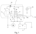
- In 1 are the outlines of a headlight 1 located inside which is a light source 2, in this case an LED.
- This light source 2 is arranged in a lighting unit 3 which has, for example, a reflector 4 and a lens 5 for guiding the light.
- a supply line 6 is connected to a power source 7 of the motor vehicle, which is designed in particular as an accumulator which supplies the supply voltage U and which can be charged by a generator G in a vehicle operated by an internal combustion engine.
- the light source 2 can be connected to this supply line 6 with the aid of a switch 8, with current flowing from the supply line 6 via the light source 2 to ground when the switch 8 is switched on, since one pole, usually the positive pole, of the current source 7 is connected to the supply line 8 , Whereas the other pole of the power source 7, here the negative pole is grounded.
- the supply line 6 and the light source 2 are also routed via a normally open contact 9a of a relay 9 to an internal electrical energy store 10 which, in a manner yet to be explained, is intended to feed the light source 2 for a certain period of time if the main power supply fails.
- This energy store 10 is arranged inside the headlight 1 and can be designed, for example, as an accumulator or as a supercapacitor.
- a diode 11 In the supply path for the energy store 10 there is a diode 11 whose function is to prevent a current flow from the energy store 10 into a defective vehicle electrical system if, for example, the supply line has a lower voltage than the energy store 10 or is short-circuited to ground.
- the diode 11 is located between the connection of the light source 2 and the supply line 6.
- resistor 12 which is preferably adjustable.
- the relay 9 i.e. its coil, is connected to the output of a linked unit 13 consisting of an AND gate and inverter, whose two inputs are connected via the switch 8 on the one hand and directly to the supply line 6 on the other.
- Another relay 14 is constantly connected to the supply line 6, with a make contact 14a being open as long as the coil voltage of the relay 14 does not drop below a limit value.
- This contact 14a is connected to the energy store 10 on the one hand and to a signal line 15 on the other hand, which leads to a display means 16 for a user.
- a further function of the resistor 12 is current limitation, which may be desirable in order to avoid an impermissibly high charging current, particularly when using a supercapacitor, which could possibly endanger the energy store 10 and/or the diode 11 .
- a monitoring device with a switch controlled by it is arranged in the headlight to monitor the voltage of the supply line 6 Supply line to the display means 16 leading to a user signal line 15 to the internal energy storage 10 switches.
- the relay 14 is used for this purpose, which keeps the make contact 14a open as long as the supply voltage U does not drop below a certain value. Otherwise, in particular in the event of a complete failure of the supply voltage U on the line 6, the switch 14a closes and the display means 16 for the user is connected to the internal energy store 10.
- This display means can, for example, be a light display which signals the failure of the light source and its remaining lighting time to the user, or a message appearing on a board display.
- the solution according to the invention does not rule out that the function of the light source is also monitored in a known manner, since the application of the invention requires a light source that is functioning per se.
- the invention primarily relates to a headlight, since special attention is to be paid to safety here, it could also be used in other lighting devices of a motor vehicle, for example in reversing lights, auxiliary headlights, indicator and brake lights and interior lighting.
Landscapes
- Engineering & Computer Science (AREA)
- Mechanical Engineering (AREA)
- Business, Economics & Management (AREA)
- Emergency Management (AREA)
- Power Engineering (AREA)
- Lighting Device Outwards From Vehicle And Optical Signal (AREA)
Description
- Die Erfindung bezieht sich auf einen Scheinwerfer für Kraftfahrzeuge mit zumindest einer Lichtquelle, die an einer Versorgungsleitung liegt, welche mit Hilfe eines Schalters an eine Stromquelle des Kraftfahrzeuges schaltbar ist, in dem Scheinwerfer ein interner elektrischer Energiespeicher angeordnet ist, der gleichfalls mit der Versorgungsleitung und mit der zumindest einen Lichtquelle verbunden ist, und bei einem Abfall/Ausfall der Spannung an der Versorgungsleitung die Lichtquelle für eine Restleuchtdauer von dem internen elektrischen Energiespeicher gespeist wird.
- Wenn im Zusammenhang mit der vorliegenden Erfindung von einem "Scheinwerfer" gesprochen wird, so ist darunter eine zum Einbau in ein Kraftfahrzeug bestimmte Einheit zu verstehen, die Beleuchtungszwecken dient, wobei es sich auch um ein Scheinwerfermodul handeln kann und beispielsweise zwei Module, eines für Fernlicht, eines für Abblendlicht, den Scheinwerfer bilden können. Ein Beleuchtungsmodul wird bevorzugt jedoch nicht notwendigerweise zur Beleuchtung des Verkehrsraums vor dem Fahrzeug dienen.
- Ein die Verkehrssicherheit gefährdendes Problem liegt in einem Zusammenbruch der Versorgungsspannung für einen Scheinwerfer. Diese Situation kann beispielsweise durch eine Leitungsunterbrechung hervorgerufen werden, die unter Umständen durch ein Lösen einer nicht gut gesicherten Steckverbindung aufgrund von Vibrationen auftreten kann. Natürlich führt auch ein Zusammenbruch oder ein drastisches Absinken der Spannung des Fahrzeugakkumulators zu einer solchen Situation.
- Es ist zwar bekannt, den Ausfall einer Lichtquelle dem Fahrer an einem Display zu signalisieren, doch ist dadurch das Problem des überraschenden Lichtausfalls mit der dadurch verbundenen Gefährdungssituation nicht behoben.
- So beschreibt die
DE 10 2013 001 976 B3 einen Scheinwerfer der eingangs genannten Art. Das DokumentDE 10 2012 018 520 A1 offenbart eine autarke Energieversorgungseinheit, welche im Notfall die Energieversorgung einer Warnleuchte übernimmt. Das Einschalten wird beispielsweise durch einen Unfall ausgelöst, kann jedoch auch händisch erfolgen. Es wird hier keine Signalleitung an die autarke Energieversorgungseinheit geschaltet noch wird eine Restleuchtdauer angezeigt. DieWO 03/057536 A1 DE 10 2004 006 404 A1 wird eine Notleuchte aktiviert, jedoch immer in Zusammenhang mit der Auslösung eines Unfallsensors. Wie dem Dokument entnehmbar ist, war es zuvor bekannt, bei einem Unfall eine Notleuchte auszulösen, und demgegenüber beschäftigt sich nun dieses Dokument mit der Möglichkeit, dass beispielsweise nicht genügend Versorgungsspannung für die Notleuchte vorhanden ist, und schlägt daher vor, bei Auslösung eines Unfallsensors und zu geringer Spannung oder einem anderen Ausfall des Beleuchtungssystems eine Pufferbatterie an die Notleuchte zu schalten. - Eine Aufgabe der Erfindung liegt darin, eine Abmilderung der Gefahren bei einem Ausfall der Spannung der Versorgungsleitung zu ermöglichen.
- Diese Aufgabe wird ausgehend von einem Scheinwerfer der eingangs genannten Art erfindungsgemäß dadurch gelöst, dass der interne elektrische Energiespeicher über eine Diode an der Versorgungsleitung liegt und zur Überwachung der Spannung der Versorgungsleitung in dem Scheinwerfer eine Überwachungseinrichtung mit einem von ihr angesteuerten Schalter angeordnet ist, welche bei Abfall der Spannung an der Versorgungsleitung eine zu einem Anzeigemittel für einen Benutzer führende Signalleitung an den internen Energiespeicher schaltet.
- Dank der Erfindung kann bei einem Ausfall oder drastischen Abfall der Spannung an der Versorgungsleitung noch eine gewisse Zeit lang ein Notbetrieb aufrechterhalten werden. Eine von dem internen Energiespeicher gespeiste Anzeige ist für den Fahrer des Kraftfahrzeuges äußerst wichtig, damit er tatsächlich auf den Ausfall der eigentlichen Versorgungsspannung hingewiesen wird und Gegenmaßnahmen treffen sowie ab diesem Augenblick eine erhöhte Aufmerksamkeit dem Fahrbetrieb zuwenden kann. Dabei wird verhindert, dass Strom von dem Energiespeicher in Richtung der externen Energieversorgung abfließt.
- Weiters empfiehlt es sich, wenn das Anzeigemittel zur Anzeige der Restleuchtdauer der zumindest einen Lichtquelle bei Versorgung ausschließlich von dem elektrischen Energiespeicher eingerichtet ist.
- Bei einer praxisgerechten Variante kann auch vorgesehen sein, dass die Versorgungsleitung und die Lichtquelle über einen Arbeitskontakt eines Relais zu dem internen elektrischen Energiespeicher geführt ist, wobei die Spule des Relais an dem Ausgang einer verknüpften Einheit, bestehend aus einem AND-Gatter und einem Inverter, liegt, dessen beide Eingänge einerseits über den Schalter und andererseits direkt an der Versorgungsleitung liegen.
- Empfehlenswert ist es, falls der elektrische Energiespeicher ein Akkumulator ist.
- Andererseits kann es auch günstig sein, falls der elektrische Energiespeicher ein Superkondensator ist.
- Bei einer vorteilhaften Ausführung kann vorgesehen sein, dass eine bei Versorgung durch den internen Energiespeicher wirksame Dimmeinrichtung für die zumindest eine Lichtquelle vorgesehen ist. Hierbei ist es günstig, wenn die Dimmeinrichtung ein zwischen dem internen Energiespeicher und der Lichtquelle liegender Vorwiderstand ist.
- Die Erfindung samt weiteren Vorteilen ist im Folgenden an Hand einer beispielsweisen Ausführungsform näher erläutert. Die in der Zeichnung veranschaulicht ist. In dieser zeigt
Fig. 1 in einer schematischen Ansicht ein Beleuchtungsmodul nach der Erfindung. - In
Fig. 1 sind die Umrisse eines Scheinwerfers 1 eingezeichnet, in dessen Inneren sich eine Lichtquelle 2, im vorliegenden Fall eine LED befindet. Diese Lichtquelle 2 ist in einer Beleuchtungseinheit 3 angeordnet, welche zur Lichtführung beispielsweise einen Reflektor 4 und eine Linse 5 besitzt. - Eine Versorgungsleitung 6 liegt an einer Stromquelle 7 des Kraftfahrzeuges, die insbesondere als Akkumulator ausgeführt ist, welcher die Versorgungsspannung U liefert und der bei einem von einem Verbrennungsmotor betriebenen Fahrzeug von einem Generator G aufgeladen werden kann. An diese Versorgungsleitung 6 ist die Lichtquelle 2 mit Hilfe eines Schalters 8 schaltbar, wobei bei eingeschaltetem Schalter 8 ein Stromfluss von der Versorgungsleitung 6 über die Lichtquelle 2 gegen Masse erfolgt, da ein Pol, üblicherweise der Pluspol der Stromquelle 7 mit der Versorgungsleitung 8 verbunden ist, wogegen der andere Pol der Stromquelle 7, hier der Minuspol an Masse liegt.
- Die Versorgungsleitung 6 und die Lichtquelle 2 sind weiters über einen Arbeitskontakt 9a eines Relais 9 zu einem internen elektrischen Energiespeicher 10 geführt, der in noch zu erläuternder Weise bei Ausfall der Hauptstromversorgung die Lichtquelle 2 eine bestimmte Zeitdauer lang speisen soll. Dieser Energiespeicher 10 ist innerhalb des Scheinwerfers 1 angeordnet und kann beispielsweise als Akkumulator oder als Superkondensator ausgebildet sein.
- In dem Versorgungspfad für den Energiespeicher 10 liegt eine Diode 11, deren Funktion darin liegt, einen Stromfluss von dem Energiespeicher 10 in ein defektes Bordnetz zu verhindern, wenn beispielsweise die Versorgungsleitung eine niedrigere Spannung als der Energiespeicher 10 aufweist oder gegen Masse kurzgeschlossen ist.
- Die Diode 11 liegt zwischen dem Anschluss der Lichtquelle 2 und der Versorgungsleitung 6.
- Man erkennt weiters, dass zwischen dem Anschluss des Energiespeichers 10 und dem Anschluss der Lichtquelle 2 ein Widerstand 12 liegt, der vorzugsweise einstellbar ist.
- Das Relais 9, d.h. dessen Spule, liegt im vorliegenden Fall an dem Ausgang einer verknüpften Einheit 13, bestehend aus einem AND-Gatter und Inverter, dessen beide Eingänge einerseits über den Schalter 8 und andererseits direkt an der Versorgungsleitung 6 liegen.
- Ein weiteres Relais 14 liegt ständig an der Versorgungsleitung 6, wobei ein Arbeitskontakt 14a offen ist, solange die Spulenspannung des Relais 14 nicht unter einen Grenzwert absinkt. Dieser Kontakt 14a ist einerseits mit dem Energiespeicher 10 und andererseits mit einer Signalleitung 15 verbunden, die zu einem Anzeigemittel 16 für einen Benutzer führt.
- Im Folgenden soll die nähere Funktion des Schweinwerfers bzw. dessen für die Erfindung wesentlichen Einzelkomponenten näher erläutert werden.
- Wenn durch einen Benutzer oder die Bordelektronik der Schalter 8 geschlossen wird, um die Lichtquelle des Scheinwerfers 1 einzuschalten, fließt ein Strom von der Leitung 6 über die Diode 11 und die Lichtquelle 2 gegen Masse. Da an beiden Eingängen der verknüpften Einheit 13 die Versorgungsspannung U liegt, ist das Relais 9 stromlos und der Kontakt 9r geschlossen, sodass über diesen Kontakt und den Widerstand 12 der interne Energiespeicher 10 aufgeladen wird bzw. an der Spannung U liegt. Dies ist die Normalfunktion.
- Falls bei geschlossenem Schalter 8 die Versorgungsspannung zusammenbricht, liegt an beiden Eingängen der verknüpften Einheit die Spannung Null oder eine für das kombinierte Glied als Null geltende Spannung, sodass der Arbeitskontakt 9a des Relais 9 dann gleichfalls geschlossen ist und nun die Lichtquelle 2 von dem internen elektrischen Energiespeicher 10 versorgt wird.
- Um ein Beispiel zu geben, werde von einer Lichtquelle für Abblendlicht mit 30 W ausgegangen. Damit die Lichtquelle etwa eine Minute lang versorgt werden kann, ist ein interner elektrischer Energiespeicher 10 mit 12 V und 50 mAh erforderlich. Dies würde einer Kapazität eines Superkondensators von ca. 25 F entsprechen. Bei verminderter Helligkeit kann eine längere Restleuchtdauer abhängig von dem Wert des Widerstandes 12 erreicht werden.
- Eine weitere Funktion des Widerstandes 12 ist eine Strombegrenzung, die erwünscht sein kann, um insbesondere bei Verwendung eines Superkondensators eine unzulässig hohen Ladestrom zu vermeiden, der gegebenenfalls den Energiespeicher 10 und/oder die Diode 11 gefährden könnte.
- Da eine Signalisierung an den Benutzer des Fahrzeugs bei einem Ausfall oder Abfall der Spannung an der Versorgungsleitung 6 gewünscht ist, ist zur Überwachung der Spannung der Versorgungsleitung 6 in dem Scheinwerfer eine Überwachungseinrichtung mit einem von ihr angesteuerten Schalter angeordnet, welche bei Abfall der Spannung an der Versorgungsleitung die zu dem Anzeigemittel 16 für einen Benutzer führende Signalleitung 15 an den internen Energiespeicher 10 schaltet. Im gezeigten Ausführungsbeispiel dient hierzu das Relais 14, welches den Arbeitskontakt 14a offen hält, solange die Versorgungsspannung U nicht unter einen gewissen Wert absinkt. Anderenfalls, insbesondere bei einem vollständigen Ausfall der Versorgungsspannung U an der Leitung 6, schließt der Schalter 14a und das Anzeigemittel 16 für den Benutzer wird an den internen Energiespeicher 10 geschaltet. Dieses Anzeigemittel kann beispielsweise eine Leuchtanzeige sein, welche dem Benutzer den Ausfall der Lichtquelle und deren Restleuchtdauer signalisiert, oder eine auf einem Boarddisplay aufscheinende Mitteilung.
- Die gezeigte Ausbildung der Schalteinrichtungen als Relais ist nur eine von vielen Möglichkeiten, welche der Fachmann bei Kenntnis des Grundgedankens der Erfindung zur Realisierung heranziehen kann. Selbstverständlich sind vollelektronische Überwachungs- und Schalteinrichtungen ebenso möglich, doch ist die gezeigte Verwendung von Relais relativ kostengünstig und ausfallssicher.
- Die erfindungsgemäße Lösung schließt natürlich nicht aus, dass auch die Funktion der Lichtquelle in bekannter Weise überwacht wird, da die Anwendung der Erfindung eine an sich funktionierende Lichtquelle voraussetzt.
- Wenngleich die Erfindung in erster Linie einen Scheinwerfer betrifft, da hier besonderes Augenmerk auf die Sicherheit zu lenken ist, so könnte sie auch bei anderen Beleuchtungseinrichtungen eines Kraftfahrzeuges angewendet werden, beispielsweise bei Rückfahrleuchten, Zusatzscheinwerfern, Blink- und Bremsleuchten und Innenraumbeleuchtungen.
-
- 1
- Scheinwerfer
- 2
- Lichtquelle
- 3
- Beleuchtungseinheit
- 4
- Reflektor
- 5
- Linse
- 6
- Versorgungsleitung
- 7
- Stromquelle
- 8
- Schalter
- 9
- Relais
- 9r
- Arbeitskontakt
- 10
- Energiespeicher
- 11
- Diode
- 12
- Widerstand
- 13
- verknüpfte Einheit bestehend aus AND-Gatter und Inverter
- 14
- Relais
- 14r
- Arbeitskontakt
- 15
- Signalleitung
- 16
- Anzeigemittel
- G
- Generator
- U
- Spannung
Claims (8)
- Scheinwerfer (1) für Kraftfahrzeuge mit zumindest einer Lichtquelle (2), die an einer Versorgungsleitung (6) liegt, welche mit Hilfe eines Schalters (8) an eine Stromquelle (7) des Kraftfahrzeuges schaltbar ist, in dem Scheinwerfer ein interner elektrischer Energiespeicher (10) angeordnet ist, der gleichfalls mit der Versorgungsleitung (6) und mit der zumindest einen Lichtquelle (2) verbunden ist, und bei einem Abfall/ Ausfall der Spannung (U) an der Versorgungsleitung die Lichtquelle für eine Restleuchtdauer von dem internen elektrischen Energiespeicher (10) gespeist wird, dadurch gekennzeichnet, dass der interne elektrische Energiespeicher (10) über eine Diode (11) an der Versorgungsleitung (6) liegt und zur Überwachung der Spannung (U) der Versorgungsleitung (6) in dem Scheinwerfer eine Überwachungseinrichtung (14) mit einem von ihr angesteuerten Schalter (14a) angeordnet ist, welche bei Abfall der Spannung an der Versorgungsleitung eine zu einem Anzeigemittel (16) für einen Benutzer führende Signalleitung (15) an den internen Energiespeicher (10) schaltet.
- Scheinwerfer nach Anspruch 1, dadurch gekennzeichnet, dass das Anzeigemittel (16) zur Anzeige der Restleuchtdauer der zumindest einen Lichtquelle (2) bei Versorgung ausschließlich von dem elektrischen Energiespeicher (10) eingerichtet ist.
- Scheinwerfer nach Anspruch 1 oder 2, dadurch gekennzeichnet, dass die Überwachungseinrichtung (14) mit einem von ihr angesteuerten Schalter (14a) von einem Relais mit Arbeitskontakt gebildet ist, wobei die Relaisspule an der Versorgungsleitung (6) liegt und die Spannung (U) an dem internen elektrischen Energiespeicher (10) über den Arbeitskontakt an die Signalleitung schaltbar ist und das Relais den Arbeitskontakt offen hält, solange die Versorgungsspannung (U) nicht unter einen gewissen Wert absinkt.
- Scheinwerfer nach einem der Ansprüche 1 bis 3, dadurch gekennzeichnet, dass elektrische Energiespeicher (10) ein Akkumulator ist
- Scheinwerfer nach einem der Ansprüche 1 bis 3, dadurch gekennzeichnet, dass der elektrische Energiespeicher (10) ein Superkondensator ist
- Scheinwerfer nach einem der Ansprüche 1 bis 5, dadurch gekennzeichnet, dass eine bei Versorgung durch den internen Energiespeicher (10) wirksame Dimmeinrichtung (12) für die zumindest eine Lichtquelle (2) vorgesehen ist.
- Scheinwerfer nach Anspruch 6, dadurch gekennzeichnet, dass die Dimmeinrichtung (12) ein zwischen dem internen Energiespeicher (10) und der Lichtquelle (2) liegender Vorwiderstand ist.
- Scheinwerfer nach einem der Ansprüche 1 bis 7, dadurch gekennzeichnet, dass die Versorgungsleitung (6) und die Lichtquelle (2) über einen Arbeitskontakt (9a) eines Relais (9) zu dem internen elektrischen Energiespeicher (10) geführt ist, wobei die Spule des Relais (9) an dem Ausgang einer verknüpften Einheit (13), bestehend aus AND-Gatter und Inverter, liegt, dessen beide Eingänge einerseits über den Schalter (8) und andererseits direkt an der Versorgungsleitung (6) liegen.
Applications Claiming Priority (2)
| Application Number | Priority Date | Filing Date | Title |
|---|---|---|---|
| ATA50114/2017A AT519611B1 (de) | 2017-02-13 | 2017-02-13 | Scheinwerfer für Kraftfahrzeuge mit zumindest einer Lichtquelle |
| PCT/AT2018/060011 WO2018145135A1 (de) | 2017-02-13 | 2018-01-16 | Scheinwerfer für kraftfahrzeuge mit zumindest einer lichtquelle |
Publications (2)
| Publication Number | Publication Date |
|---|---|
| EP3580096A1 EP3580096A1 (de) | 2019-12-18 |
| EP3580096B1 true EP3580096B1 (de) | 2022-03-09 |
Family
ID=61054063
Family Applications (1)
| Application Number | Title | Priority Date | Filing Date |
|---|---|---|---|
| EP18701657.1A Active EP3580096B1 (de) | 2017-02-13 | 2018-01-16 | Scheinwerfer für kraftfahrzeuge mit zumindest einer lichtquelle |
Country Status (5)
| Country | Link |
|---|---|
| EP (1) | EP3580096B1 (de) |
| KR (1) | KR102222591B1 (de) |
| CN (1) | CN110248844B (de) |
| AT (1) | AT519611B1 (de) |
| WO (1) | WO2018145135A1 (de) |
Family Cites Families (10)
| Publication number | Priority date | Publication date | Assignee | Title |
|---|---|---|---|---|
| DE415503C (de) * | 1923-05-22 | 1925-06-26 | Maurice Andre Saran | Elektrische Beleuchtungsanlage, insbesondere fuer Kraftfahrzeuge |
| KR100389090B1 (ko) * | 2000-09-15 | 2003-06-25 | 임승룡 | 차량화재방지를 위한 전원장치 |
| DE102004006404A1 (de) * | 2004-02-10 | 2004-09-16 | Daimlerchrysler Ag | Warneinrichtung für ein Fahrzeug |
| CN101501738A (zh) * | 2006-04-17 | 2009-08-05 | 总锁有限责任公司 | 拖车报警器 |
| CN101188067A (zh) * | 2007-12-13 | 2008-05-28 | 赵兵 | 主动防止汽车连环相撞的自动报警系统 |
| DE102012017520A1 (de) * | 2012-09-05 | 2014-03-06 | Feindrahtwerk Adolf Edelhoff Gmbh & Co. Kg | Verfahren zur Zinnbeschichtung eines metallischen Substrats,Verfahren zur Härtung einer Zinnschicht, sowie Draht mit einer Zinnbeschichtung |
| DE102012018520A1 (de) * | 2012-09-18 | 2013-03-21 | Daimler Ag | Notfallsystem für ein Kraftfahrzeug |
| DE102013001976B3 (de) * | 2013-02-05 | 2014-02-27 | Arkadij Gozulak | Lichtsignaleinrichtung für ein Fahrzeug, insbesondere für einen PKW |
| JP5730975B2 (ja) * | 2013-10-11 | 2015-06-10 | 富士重工業株式会社 | 電動車両 |
| CN104908683B (zh) * | 2015-05-29 | 2017-05-10 | 大连楼兰科技股份有限公司 | 基于汽车仪表盘数据采集器的汽车碰撞无线检测和报警装置及其方法 |
-
2017
- 2017-02-13 AT ATA50114/2017A patent/AT519611B1/de active
-
2018
- 2018-01-16 WO PCT/AT2018/060011 patent/WO2018145135A1/de not_active Ceased
- 2018-01-16 KR KR1020197026095A patent/KR102222591B1/ko active Active
- 2018-01-16 CN CN201880011452.6A patent/CN110248844B/zh active Active
- 2018-01-16 EP EP18701657.1A patent/EP3580096B1/de active Active
Also Published As
| Publication number | Publication date |
|---|---|
| AT519611B1 (de) | 2018-11-15 |
| KR102222591B1 (ko) | 2021-03-05 |
| KR20190115060A (ko) | 2019-10-10 |
| EP3580096A1 (de) | 2019-12-18 |
| WO2018145135A1 (de) | 2018-08-16 |
| CN110248844B (zh) | 2022-11-25 |
| CN110248844A (zh) | 2019-09-17 |
| AT519611A1 (de) | 2018-08-15 |
Similar Documents
| Publication | Publication Date | Title |
|---|---|---|
| EP0483650B1 (de) | Schaltungsanordung für ein Zugfahrzeug | |
| DE2051391A1 (de) | Tragbare Leuchte, insbesondere Kopfleuchte | |
| DE4137611A1 (de) | Richtungs- und warnblinkanlage fuer ein fahrzeug, insbesondere fuer ein kraftfahrzeug | |
| EP3580096B1 (de) | Scheinwerfer für kraftfahrzeuge mit zumindest einer lichtquelle | |
| DE2527877C3 (de) | Steuereinrichtung zum selbsttätigen Schalten von Leuchten | |
| DE10355046B4 (de) | Steuereinrichtung für Außenlichteinheiten von Fahrzeugen, insbesondere Kraftfahrzeugen | |
| DE10359196A1 (de) | Leuchtmittelanordnung und Beleuchtungseinrichtung für ein Kraftfahrzeug | |
| DE102016224810A1 (de) | Kraftfahrzeug mit einem Elektromotor, insbesondere Hybrid- oder Elektrofahrzeug | |
| DE2044383A1 (de) | Elektrische Kontrollschaltung fur eine zentrale Warnleuchte von Fahrzeugen | |
| EP2146551A2 (de) | Ansteuerung für LED-Lichtquelle, insbesondere in der Eisenbahnbeleuchtung | |
| DE102016122370A1 (de) | Not-Befehlsgerät und Sicherheitseinrichtung mit einem Not-Befehlsgerät | |
| DE102013001976B3 (de) | Lichtsignaleinrichtung für ein Fahrzeug, insbesondere für einen PKW | |
| DE2700995A1 (de) | Ueberwachungssystem fuer einen elektrischen stromdurchflossenen verbraucher | |
| DE2227964A1 (de) | Kontrollvorrichtung fur Kraftfahrzeug Beleuchtungsanlage | |
| DE4342586A1 (de) | Anzeigeeinrichtung für elektrische Steuergeräte | |
| DE102007056139A1 (de) | Kraftfahrzeug mit einer Gefahrenwarnvorrichtung und Verfahren zur Gefahrenermittlung | |
| DE102013113007A1 (de) | Steuereinrichtung für Außenlichteinheiten von Fahrzeugen | |
| DE102004052618A1 (de) | Sicherheitssensor | |
| DE202004004517U1 (de) | Sicherheitsnotlicht für Kraftfahrzeuge | |
| DE10362071A1 (de) | Blinkendes Stopplicht am Kraftfahrzeug/en | |
| DE1455749C (de) | Warnblinkeinnchtung | |
| DE896510C (de) | Schalter fuer Strassenbahn-Fahrtrichtungsanzeiger | |
| DE102013100712A1 (de) | Anzeigevorrichtung | |
| DE102004036342A1 (de) | Anhänger-Beleuchtungsanordnung für eine Zugfahrzeug-Anhänger-Kombination | |
| DE202012100148U1 (de) | Fahrzeugbeleuchtungsmodul |
Legal Events
| Date | Code | Title | Description |
|---|---|---|---|
| STAA | Information on the status of an ep patent application or granted ep patent |
Free format text: STATUS: UNKNOWN |
|
| STAA | Information on the status of an ep patent application or granted ep patent |
Free format text: STATUS: THE INTERNATIONAL PUBLICATION HAS BEEN MADE |
|
| PUAI | Public reference made under article 153(3) epc to a published international application that has entered the european phase |
Free format text: ORIGINAL CODE: 0009012 |
|
| STAA | Information on the status of an ep patent application or granted ep patent |
Free format text: STATUS: REQUEST FOR EXAMINATION WAS MADE |
|
| 17P | Request for examination filed |
Effective date: 20190730 |
|
| AK | Designated contracting states |
Kind code of ref document: A1 Designated state(s): AL AT BE BG CH CY CZ DE DK EE ES FI FR GB GR HR HU IE IS IT LI LT LU LV MC MK MT NL NO PL PT RO RS SE SI SK SM TR |
|
| AX | Request for extension of the european patent |
Extension state: BA ME |
|
| DAV | Request for validation of the european patent (deleted) | ||
| DAX | Request for extension of the european patent (deleted) | ||
| GRAP | Despatch of communication of intention to grant a patent |
Free format text: ORIGINAL CODE: EPIDOSNIGR1 |
|
| STAA | Information on the status of an ep patent application or granted ep patent |
Free format text: STATUS: GRANT OF PATENT IS INTENDED |
|
| GRAS | Grant fee paid |
Free format text: ORIGINAL CODE: EPIDOSNIGR3 |
|
| INTG | Intention to grant announced |
Effective date: 20211209 |
|
| GRAA | (expected) grant |
Free format text: ORIGINAL CODE: 0009210 |
|
| STAA | Information on the status of an ep patent application or granted ep patent |
Free format text: STATUS: THE PATENT HAS BEEN GRANTED |
|
| AK | Designated contracting states |
Kind code of ref document: B1 Designated state(s): AL AT BE BG CH CY CZ DE DK EE ES FI FR GB GR HR HU IE IS IT LI LT LU LV MC MK MT NL NO PL PT RO RS SE SI SK SM TR |
|
| REG | Reference to a national code |
Ref country code: CH Ref legal event code: EP Ref country code: AT Ref legal event code: REF Ref document number: 1473878 Country of ref document: AT Kind code of ref document: T Effective date: 20220315 |
|
| REG | Reference to a national code |
Ref country code: IE Ref legal event code: FG4D Free format text: LANGUAGE OF EP DOCUMENT: GERMAN |
|
| REG | Reference to a national code |
Ref country code: DE Ref legal event code: R096 Ref document number: 502018009023 Country of ref document: DE |
|
| REG | Reference to a national code |
Ref country code: LT Ref legal event code: MG9D |
|
| REG | Reference to a national code |
Ref country code: NL Ref legal event code: MP Effective date: 20220309 |
|
| PG25 | Lapsed in a contracting state [announced via postgrant information from national office to epo] |
Ref country code: SE Free format text: LAPSE BECAUSE OF FAILURE TO SUBMIT A TRANSLATION OF THE DESCRIPTION OR TO PAY THE FEE WITHIN THE PRESCRIBED TIME-LIMIT Effective date: 20220309 Ref country code: RS Free format text: LAPSE BECAUSE OF FAILURE TO SUBMIT A TRANSLATION OF THE DESCRIPTION OR TO PAY THE FEE WITHIN THE PRESCRIBED TIME-LIMIT Effective date: 20220309 Ref country code: NO Free format text: LAPSE BECAUSE OF FAILURE TO SUBMIT A TRANSLATION OF THE DESCRIPTION OR TO PAY THE FEE WITHIN THE PRESCRIBED TIME-LIMIT Effective date: 20220609 Ref country code: LT Free format text: LAPSE BECAUSE OF FAILURE TO SUBMIT A TRANSLATION OF THE DESCRIPTION OR TO PAY THE FEE WITHIN THE PRESCRIBED TIME-LIMIT Effective date: 20220309 Ref country code: HR Free format text: LAPSE BECAUSE OF FAILURE TO SUBMIT A TRANSLATION OF THE DESCRIPTION OR TO PAY THE FEE WITHIN THE PRESCRIBED TIME-LIMIT Effective date: 20220309 Ref country code: BG Free format text: LAPSE BECAUSE OF FAILURE TO SUBMIT A TRANSLATION OF THE DESCRIPTION OR TO PAY THE FEE WITHIN THE PRESCRIBED TIME-LIMIT Effective date: 20220609 |
|
| PG25 | Lapsed in a contracting state [announced via postgrant information from national office to epo] |
Ref country code: LV Free format text: LAPSE BECAUSE OF FAILURE TO SUBMIT A TRANSLATION OF THE DESCRIPTION OR TO PAY THE FEE WITHIN THE PRESCRIBED TIME-LIMIT Effective date: 20220309 Ref country code: GR Free format text: LAPSE BECAUSE OF FAILURE TO SUBMIT A TRANSLATION OF THE DESCRIPTION OR TO PAY THE FEE WITHIN THE PRESCRIBED TIME-LIMIT Effective date: 20220610 Ref country code: FI Free format text: LAPSE BECAUSE OF FAILURE TO SUBMIT A TRANSLATION OF THE DESCRIPTION OR TO PAY THE FEE WITHIN THE PRESCRIBED TIME-LIMIT Effective date: 20220309 |
|
| PG25 | Lapsed in a contracting state [announced via postgrant information from national office to epo] |
Ref country code: NL Free format text: LAPSE BECAUSE OF FAILURE TO SUBMIT A TRANSLATION OF THE DESCRIPTION OR TO PAY THE FEE WITHIN THE PRESCRIBED TIME-LIMIT Effective date: 20220309 |
|
| PG25 | Lapsed in a contracting state [announced via postgrant information from national office to epo] |
Ref country code: SM Free format text: LAPSE BECAUSE OF FAILURE TO SUBMIT A TRANSLATION OF THE DESCRIPTION OR TO PAY THE FEE WITHIN THE PRESCRIBED TIME-LIMIT Effective date: 20220309 Ref country code: SK Free format text: LAPSE BECAUSE OF FAILURE TO SUBMIT A TRANSLATION OF THE DESCRIPTION OR TO PAY THE FEE WITHIN THE PRESCRIBED TIME-LIMIT Effective date: 20220309 Ref country code: RO Free format text: LAPSE BECAUSE OF FAILURE TO SUBMIT A TRANSLATION OF THE DESCRIPTION OR TO PAY THE FEE WITHIN THE PRESCRIBED TIME-LIMIT Effective date: 20220309 Ref country code: PT Free format text: LAPSE BECAUSE OF FAILURE TO SUBMIT A TRANSLATION OF THE DESCRIPTION OR TO PAY THE FEE WITHIN THE PRESCRIBED TIME-LIMIT Effective date: 20220711 Ref country code: ES Free format text: LAPSE BECAUSE OF FAILURE TO SUBMIT A TRANSLATION OF THE DESCRIPTION OR TO PAY THE FEE WITHIN THE PRESCRIBED TIME-LIMIT Effective date: 20220309 Ref country code: EE Free format text: LAPSE BECAUSE OF FAILURE TO SUBMIT A TRANSLATION OF THE DESCRIPTION OR TO PAY THE FEE WITHIN THE PRESCRIBED TIME-LIMIT Effective date: 20220309 Ref country code: CZ Free format text: LAPSE BECAUSE OF FAILURE TO SUBMIT A TRANSLATION OF THE DESCRIPTION OR TO PAY THE FEE WITHIN THE PRESCRIBED TIME-LIMIT Effective date: 20220309 |
|
| PG25 | Lapsed in a contracting state [announced via postgrant information from national office to epo] |
Ref country code: PL Free format text: LAPSE BECAUSE OF FAILURE TO SUBMIT A TRANSLATION OF THE DESCRIPTION OR TO PAY THE FEE WITHIN THE PRESCRIBED TIME-LIMIT Effective date: 20220309 Ref country code: IS Free format text: LAPSE BECAUSE OF FAILURE TO SUBMIT A TRANSLATION OF THE DESCRIPTION OR TO PAY THE FEE WITHIN THE PRESCRIBED TIME-LIMIT Effective date: 20220709 Ref country code: AL Free format text: LAPSE BECAUSE OF FAILURE TO SUBMIT A TRANSLATION OF THE DESCRIPTION OR TO PAY THE FEE WITHIN THE PRESCRIBED TIME-LIMIT Effective date: 20220309 |
|
| REG | Reference to a national code |
Ref country code: DE Ref legal event code: R097 Ref document number: 502018009023 Country of ref document: DE |
|
| PLBE | No opposition filed within time limit |
Free format text: ORIGINAL CODE: 0009261 |
|
| STAA | Information on the status of an ep patent application or granted ep patent |
Free format text: STATUS: NO OPPOSITION FILED WITHIN TIME LIMIT |
|
| PG25 | Lapsed in a contracting state [announced via postgrant information from national office to epo] |
Ref country code: DK Free format text: LAPSE BECAUSE OF FAILURE TO SUBMIT A TRANSLATION OF THE DESCRIPTION OR TO PAY THE FEE WITHIN THE PRESCRIBED TIME-LIMIT Effective date: 20220309 |
|
| 26N | No opposition filed |
Effective date: 20221212 |
|
| PG25 | Lapsed in a contracting state [announced via postgrant information from national office to epo] |
Ref country code: SI Free format text: LAPSE BECAUSE OF FAILURE TO SUBMIT A TRANSLATION OF THE DESCRIPTION OR TO PAY THE FEE WITHIN THE PRESCRIBED TIME-LIMIT Effective date: 20220309 |
|
| P01 | Opt-out of the competence of the unified patent court (upc) registered |
Effective date: 20230528 |
|
| PG25 | Lapsed in a contracting state [announced via postgrant information from national office to epo] |
Ref country code: IT Free format text: LAPSE BECAUSE OF FAILURE TO SUBMIT A TRANSLATION OF THE DESCRIPTION OR TO PAY THE FEE WITHIN THE PRESCRIBED TIME-LIMIT Effective date: 20220309 |
|
| REG | Reference to a national code |
Ref country code: CH Ref legal event code: PL |
|
| GBPC | Gb: european patent ceased through non-payment of renewal fee |
Effective date: 20230116 |
|
| PG25 | Lapsed in a contracting state [announced via postgrant information from national office to epo] |
Ref country code: LU Free format text: LAPSE BECAUSE OF NON-PAYMENT OF DUE FEES Effective date: 20230116 |
|
| REG | Reference to a national code |
Ref country code: BE Ref legal event code: MM Effective date: 20230131 |
|
| PG25 | Lapsed in a contracting state [announced via postgrant information from national office to epo] |
Ref country code: LI Free format text: LAPSE BECAUSE OF NON-PAYMENT OF DUE FEES Effective date: 20230131 Ref country code: GB Free format text: LAPSE BECAUSE OF NON-PAYMENT OF DUE FEES Effective date: 20230116 Ref country code: CH Free format text: LAPSE BECAUSE OF NON-PAYMENT OF DUE FEES Effective date: 20230131 |
|
| PG25 | Lapsed in a contracting state [announced via postgrant information from national office to epo] |
Ref country code: BE Free format text: LAPSE BECAUSE OF NON-PAYMENT OF DUE FEES Effective date: 20230131 |
|
| PG25 | Lapsed in a contracting state [announced via postgrant information from national office to epo] |
Ref country code: IE Free format text: LAPSE BECAUSE OF NON-PAYMENT OF DUE FEES Effective date: 20230116 |
|
| REG | Reference to a national code |
Ref country code: AT Ref legal event code: MM01 Ref document number: 1473878 Country of ref document: AT Kind code of ref document: T Effective date: 20230116 |
|
| PG25 | Lapsed in a contracting state [announced via postgrant information from national office to epo] |
Ref country code: AT Free format text: LAPSE BECAUSE OF NON-PAYMENT OF DUE FEES Effective date: 20230116 |
|
| PG25 | Lapsed in a contracting state [announced via postgrant information from national office to epo] |
Ref country code: AT Free format text: LAPSE BECAUSE OF NON-PAYMENT OF DUE FEES Effective date: 20230116 |
|
| PG25 | Lapsed in a contracting state [announced via postgrant information from national office to epo] |
Ref country code: MC Free format text: LAPSE BECAUSE OF FAILURE TO SUBMIT A TRANSLATION OF THE DESCRIPTION OR TO PAY THE FEE WITHIN THE PRESCRIBED TIME-LIMIT Effective date: 20220309 |
|
| PG25 | Lapsed in a contracting state [announced via postgrant information from national office to epo] |
Ref country code: MC Free format text: LAPSE BECAUSE OF FAILURE TO SUBMIT A TRANSLATION OF THE DESCRIPTION OR TO PAY THE FEE WITHIN THE PRESCRIBED TIME-LIMIT Effective date: 20220309 |
|
| PG25 | Lapsed in a contracting state [announced via postgrant information from national office to epo] |
Ref country code: CY Free format text: LAPSE BECAUSE OF FAILURE TO SUBMIT A TRANSLATION OF THE DESCRIPTION OR TO PAY THE FEE WITHIN THE PRESCRIBED TIME-LIMIT; INVALID AB INITIO Effective date: 20180116 |
|
| PG25 | Lapsed in a contracting state [announced via postgrant information from national office to epo] |
Ref country code: HU Free format text: LAPSE BECAUSE OF FAILURE TO SUBMIT A TRANSLATION OF THE DESCRIPTION OR TO PAY THE FEE WITHIN THE PRESCRIBED TIME-LIMIT; INVALID AB INITIO Effective date: 20180116 |
|
| REG | Reference to a national code |
Ref country code: DE Ref legal event code: R084 Ref document number: 502018009023 Country of ref document: DE |
|
| PG25 | Lapsed in a contracting state [announced via postgrant information from national office to epo] |
Ref country code: TR Free format text: LAPSE BECAUSE OF FAILURE TO SUBMIT A TRANSLATION OF THE DESCRIPTION OR TO PAY THE FEE WITHIN THE PRESCRIBED TIME-LIMIT Effective date: 20220309 |
|
| PGFP | Annual fee paid to national office [announced via postgrant information from national office to epo] |
Ref country code: DE Payment date: 20260120 Year of fee payment: 9 |
|
| PGFP | Annual fee paid to national office [announced via postgrant information from national office to epo] |
Ref country code: FR Payment date: 20260128 Year of fee payment: 9 |