EP3576932B1 - Dispositif de manipulation et procédé de fermeture de languettes de fond extérieures d'un suremballage - Google Patents
Dispositif de manipulation et procédé de fermeture de languettes de fond extérieures d'un suremballage Download PDFInfo
- Publication number
- EP3576932B1 EP3576932B1 EP18700395.9A EP18700395A EP3576932B1 EP 3576932 B1 EP3576932 B1 EP 3576932B1 EP 18700395 A EP18700395 A EP 18700395A EP 3576932 B1 EP3576932 B1 EP 3576932B1
- Authority
- EP
- European Patent Office
- Prior art keywords
- bottom flaps
- closing
- slide elements
- box blank
- flaps
- Prior art date
- Legal status (The legal status is an assumption and is not a legal conclusion. Google has not performed a legal analysis and makes no representation as to the accuracy of the status listed.)
- Active
Links
- 238000004806 packaging method and process Methods 0.000 title claims description 53
- 238000000034 method Methods 0.000 title claims description 36
- 239000000853 adhesive Substances 0.000 claims description 26
- 230000001070 adhesive effect Effects 0.000 claims description 25
- 230000007246 mechanism Effects 0.000 claims description 24
- 238000000151 deposition Methods 0.000 claims description 2
- 239000003292 glue Substances 0.000 description 9
- 230000008569 process Effects 0.000 description 7
- 238000004519 manufacturing process Methods 0.000 description 3
- 230000007704 transition Effects 0.000 description 3
- 239000002390 adhesive tape Substances 0.000 description 2
- 238000010276 construction Methods 0.000 description 2
- 238000007789 sealing Methods 0.000 description 2
- 230000008859 change Effects 0.000 description 1
- 238000005520 cutting process Methods 0.000 description 1
- 238000009826 distribution Methods 0.000 description 1
- 230000000694 effects Effects 0.000 description 1
- 238000005516 engineering process Methods 0.000 description 1
- 238000012986 modification Methods 0.000 description 1
- 230000004048 modification Effects 0.000 description 1
- 238000000926 separation method Methods 0.000 description 1
- 230000001360 synchronised effect Effects 0.000 description 1
- XLYOFNOQVPJJNP-UHFFFAOYSA-N water Substances O XLYOFNOQVPJJNP-UHFFFAOYSA-N 0.000 description 1
Images


Classifications
-
- B—PERFORMING OPERATIONS; TRANSPORTING
- B31—MAKING ARTICLES OF PAPER, CARDBOARD OR MATERIAL WORKED IN A MANNER ANALOGOUS TO PAPER; WORKING PAPER, CARDBOARD OR MATERIAL WORKED IN A MANNER ANALOGOUS TO PAPER
- B31B—MAKING CONTAINERS OF PAPER, CARDBOARD OR MATERIAL WORKED IN A MANNER ANALOGOUS TO PAPER
- B31B50/00—Making rigid or semi-rigid containers, e.g. boxes or cartons
- B31B50/26—Folding sheets, blanks or webs
- B31B50/52—Folding sheets, blanks or webs by reciprocating or oscillating members, e.g. fingers
-
- B—PERFORMING OPERATIONS; TRANSPORTING
- B31—MAKING ARTICLES OF PAPER, CARDBOARD OR MATERIAL WORKED IN A MANNER ANALOGOUS TO PAPER; WORKING PAPER, CARDBOARD OR MATERIAL WORKED IN A MANNER ANALOGOUS TO PAPER
- B31B—MAKING CONTAINERS OF PAPER, CARDBOARD OR MATERIAL WORKED IN A MANNER ANALOGOUS TO PAPER
- B31B50/00—Making rigid or semi-rigid containers, e.g. boxes or cartons
- B31B50/74—Auxiliary operations
- B31B50/76—Opening and distending flattened articles
-
- B—PERFORMING OPERATIONS; TRANSPORTING
- B31—MAKING ARTICLES OF PAPER, CARDBOARD OR MATERIAL WORKED IN A MANNER ANALOGOUS TO PAPER; WORKING PAPER, CARDBOARD OR MATERIAL WORKED IN A MANNER ANALOGOUS TO PAPER
- B31B—MAKING CONTAINERS OF PAPER, CARDBOARD OR MATERIAL WORKED IN A MANNER ANALOGOUS TO PAPER
- B31B2110/00—Shape of rigid or semi-rigid containers
- B31B2110/30—Shape of rigid or semi-rigid containers having a polygonal cross section
- B31B2110/35—Shape of rigid or semi-rigid containers having a polygonal cross section rectangular, e.g. square
-
- B—PERFORMING OPERATIONS; TRANSPORTING
- B31—MAKING ARTICLES OF PAPER, CARDBOARD OR MATERIAL WORKED IN A MANNER ANALOGOUS TO PAPER; WORKING PAPER, CARDBOARD OR MATERIAL WORKED IN A MANNER ANALOGOUS TO PAPER
- B31B—MAKING CONTAINERS OF PAPER, CARDBOARD OR MATERIAL WORKED IN A MANNER ANALOGOUS TO PAPER
- B31B2120/00—Construction of rigid or semi-rigid containers
- B31B2120/30—Construction of rigid or semi-rigid containers collapsible; temporarily collapsed during manufacturing
- B31B2120/302—Construction of rigid or semi-rigid containers collapsible; temporarily collapsed during manufacturing collapsible into a flat condition
-
- B—PERFORMING OPERATIONS; TRANSPORTING
- B31—MAKING ARTICLES OF PAPER, CARDBOARD OR MATERIAL WORKED IN A MANNER ANALOGOUS TO PAPER; WORKING PAPER, CARDBOARD OR MATERIAL WORKED IN A MANNER ANALOGOUS TO PAPER
- B31B—MAKING CONTAINERS OF PAPER, CARDBOARD OR MATERIAL WORKED IN A MANNER ANALOGOUS TO PAPER
- B31B50/00—Making rigid or semi-rigid containers, e.g. boxes or cartons
- B31B50/60—Uniting opposed surfaces or edges; Taping
- B31B50/62—Uniting opposed surfaces or edges; Taping by adhesives
-
- B—PERFORMING OPERATIONS; TRANSPORTING
- B65—CONVEYING; PACKING; STORING; HANDLING THIN OR FILAMENTARY MATERIAL
- B65B—MACHINES, APPARATUS OR DEVICES FOR, OR METHODS OF, PACKAGING ARTICLES OR MATERIALS; UNPACKING
- B65B43/00—Forming, feeding, opening or setting-up containers or receptacles in association with packaging
- B65B43/26—Opening or distending bags; Opening, erecting, or setting-up boxes, cartons, or carton blanks
- B65B43/265—Opening, erecting or setting-up boxes, cartons or carton blanks
-
- B—PERFORMING OPERATIONS; TRANSPORTING
- B65—CONVEYING; PACKING; STORING; HANDLING THIN OR FILAMENTARY MATERIAL
- B65B—MACHINES, APPARATUS OR DEVICES FOR, OR METHODS OF, PACKAGING ARTICLES OR MATERIALS; UNPACKING
- B65B5/00—Packaging individual articles in containers or receptacles, e.g. bags, sacks, boxes, cartons, cans, jars
- B65B5/02—Machines characterised by incorporation of means for making the containers or receptacles
- B65B5/024—Machines characterised by incorporation of means for making the containers or receptacles for making containers from preformed blanks
Definitions
- the present invention relates to a handling device for closing outer bottom flaps of an outer packaging with the features of independent claim 1.
- the invention relates to the production of a carton outer packaging, in particular to the production of an RSC carton.
- cardboard outer packaging can be understood to mean outer packaging that is produced from suitable cardboard blanks.
- the RSC stands for "regular slotted carton", and it is the typical box construction with four flaps or bottom flaps at the bottom box opening and four flaps or top flaps at the top box opening.
- the bottom flaps or top flaps with the shorter side length are referred to as the smaller flaps or flaps.
- the bottom flaps or top flaps with the longer side length that create the box length are called the main flaps.
- the main tabs meet in the middle, where they can be glued together with a plastic or water-activated tape, for example.
- the carton blank is first folded into the box construction with the top and bottom box openings open, and an overlapping side flap is glued, forming a parallelepiped open on both sides. Then the smaller inner bottom flaps with the shorter side length are folded inwards until they are arranged essentially perpendicularly to the respectively connected side wall.
- the outer surfaces of the correspondingly folded smaller inner bottom flaps are usually provided with an adhesive or the like. Now the larger outer bottom flaps or main flaps are folded in the direction of the smaller inner bottom flaps and pressed against them, so that the larger outer bottom flaps or main flaps stick to the smaller inner bottom flaps get connected. According to the devices known in the prior art, the larger outer bottom flaps of cartons are actually closed by means of pivotable flaps.
- a flap is required for each larger outer bottom flap to be closed, with each flap being driven by its own pneumatic cylinder or another suitable drive.
- each cylinder must be adjusted separately.
- two flaps and two suitable drives are required to close the larger outer bottom flaps of each carton. If several boxes are to be processed at the same time, the number of flaps and drives required increases accordingly.
- the patent specification DE 43 25 181 C2 describes a handling device in which at least for the two outer surfaces of an end face there is a folding device which has a pre-folding unit for each outer flap, which bends and pivots each outer flap around its fold line without bringing the outer flap to rest against the inner flaps; and a common closing unit, the actuation of which brings the two angled outer links into contact with the inner links.
- a first step the outer flaps are only bent around their fold line and enclose an angle of about 20 to 30 degrees with the inner flaps, for example.
- the outer link plates which have already been angled, are brought into contact with the inner link plates.
- This movement component can be applied by a ram, which is adjusted essentially vertically to the plane of the inner straps.
- the separation of the adjustment required for complete folding into two movement components which are aligned essentially orthogonally to one another enables short adjustment paths for each movement component.
- the JP 2014 162216 A discloses a generic handling device for closing outer bottom flaps of an outer packaging, the handling device comprising a holding device for a mounted cardboard blank, an adhesive application device and a closing module with a closing unit with two horizontally movable slides for closing the outer bottom flaps.
- the invention relates to a handling device that includes at least one holding device for a mounted cardboard blank.
- a mounted carton blank is to be understood in particular as a pre-glued carton blank which, after being mounted, forms a box shape with two opposite openings, with the two openings being flanked by open bottom flaps or top flaps. Folding lines are formed between the bottom flaps or top flaps and the side walls of the carton blank, which enable the bottom flaps or top flaps to be folded over or folded in in a controlled manner. This is particularly preferably an RSC cardboard blank.
- bottom flaps is not to be understood in particular as being restrictive in relation to the arrangement in the finished product.
- a carton blank that is closed at the bottom and manufactured using the handling device described here can then be tilted by about 90° and loaded and closed from the side, so that the flaps referred to as bottom flaps within the present application are arranged laterally in the finished product.
- At least one adhesive application device is provided with which, for example, glue or another suitable adhesive can be applied to the outsides of folded-in inner bottom flaps in order to glue them to the subsequently folded-in outer bottom flaps.
- a suitable adhesive is applied with the adhesive application device in the area of the contact point or contact line of the two folded-in outer bottom flaps.
- the two outer bottom flaps are connected to each other with an adhesive strip.
- a closure module which comprises at least one closure unit, is provided for folding in the outer bottom flaps.
- the closing unit includes two sliding elements designed to be movable relative to one another in a horizontal plane.
- the sliding elements comprise spring-loaded support elements.
- the holding device provides first holding devices for clampingly holding inner side surfaces of the mounted carton blank.
- the first holding devices brace themselves between the insides of two opposing side walls of the mounted cardboard blank.
- the holding device comprises at least one second holding device for folding in and/or holding the at least one inner bottom flap of the mounted carton blank.
- suction devices such as suction cups, suction cups that can be subjected to a vacuum, or the like.
- the carton blank is in particular pulled up over a connecting link, with the inner bottom flaps being folded in.
- the second holding devices attach to the folded-in inner bottom flaps in order to hold the cardboard blank that has been pulled open.
- the second holding devices suck on the - usually two - inner bottom flaps and pull them in the direction of the interior space formed between the side walls of the mounted carton blank, as a result of which the inner bottom flaps are folded in and held by 90° along the fold lines.
- a method for closing outer bottom flaps of an outer packaging is disclosed.
- the carton blanks are provided as pre-glued flat blanks in a magazine or similar and must first be drawn into the box shape that is open on both sides.
- cardboard blanks that have already been mounted can also be provided for the method.
- the mounted carton blank is gripped by the first and/or second holding means of the holding device described above, with the inner bottom flaps being folded in beforehand or simultaneously or directly thereafter along the fold lines by 90° towards the interior of the box shape.
- an adhesive can be applied at least in regions to the outer side surfaces of the folded-in inner bottom flaps.
- the carton blank prepared in this way is arranged between two sliding elements of a closing unit.
- the mounted carton blank with the inner bottom flaps folded in is first arranged between two sliding elements of a closing unit and the outer bottom flaps are closed.
- Adhesive application device the adhesive are applied to the outer side surfaces of the folded inner bottom flaps.
- the prepared carton blank is arranged in particular between the two sliding elements of the closing unit in such a way that a floor level formed by the folded-in inner bottom flaps is located directly on or slightly above a support level formed by the upper side of the sliding elements.
- the outer bottom flaps of the prepared carton blank can now be closed by folding them in by 90° along the respective fold line by moving the two sliding elements of the closing unit towards one another in a horizontal plane which is formed directly below the bottom plane of the outer packaging formed by the folded-in inner bottom flaps.
- the two sliding elements are each moved towards one another at the same relative speed until they essentially abut one another.
- no adhesive is applied to the outer side surfaces of the inner bottom flaps.
- the folded-in outer bottom flaps are closed by means of an adhesive tape or the like along a contact line formed between the two folded-in outer bottom flaps.
- the adhesive application device can now apply an adhesive tape or the like from below.
- the sliding elements can be moved towards one another again and, if necessary, the carton blank can also be pressed from above against the preferably spring-loaded contact surface of the sliding elements by a downward movement of the holding device.
- an embodiment of the method can provide a combination of adhesive application to the outer side surfaces of the inner bottom flaps and adhesive application to the folded-in outer bottom flaps.
- the closure module comprises a plurality of closure units, each with two sliding elements designed to be movable relative to one another in a horizontal plane, so that a number of carton blanks that corresponds to the number of closing units can be processed simultaneously within the closing module.
- the sliding elements of all closing units can be arranged in a common horizontal plane, so that the upper sides of all sliding elements lie in a common support plane.
- At least the sliding elements of a closing unit are arranged in a motion-coupled manner on a common drive mechanism in such a way that, at the same time as the first sliding element of the closing unit moves in a first direction, a counter-movement of the second sliding element of the closing unit takes place in the opposite direction. so that the sliding elements of a closing unit move either towards or away from each other at the same relative speed. Due to the coupled movement of the two sliding elements, the two outer bottom flaps of a carton blank are folded over or folded in at the same time, with only a single drive being necessary.
- the sliding elements of all closure units - as described above - are arranged in a motion-coupled manner on a common drive mechanism, so that only a single drive is required for the simultaneous processing of several carton blanks, which means that the closure module can be manufactured cost-effectively .
- the drive mechanism can comprise at least one circulating conveyor arranged on a drive means with an upper run and a lower run, with one of the sliding elements of a closing unit being arranged on the upper run of the conveyor and the other sliding element of the closing unit being arranged on the lower run of the conveyor. Since the direction of movement of the lower run is opposite to the direction of movement of the upper run in a circulating conveyor, the arrangement of the sliding elements described causes the sliding element of a sealing unit arranged on the upper run to move in the opposite direction to the sliding element of the sealing unit arranged on the lower run.
- the drive mechanism can preferably comprise two conveying means guided in parallel and arranged on the drive means via a common drive shaft.
- the sliding elements are each arranged between the two funding means and each attached to the two funding means.
- the sliding elements are particularly preferably arranged alternately on both sides on the upper strand of both conveyors or on both sides of the lower strand of both conveyors.
- An electric motor, a servo drive or the like is provided as the drive means for the conveying means.
- the at least one preferably circulating conveying means is a toothed belt, for example.
- a large number of sliding elements and thus a large number of closing units can be operated via a single servo drive or another suitable drive means.
- Such a central drive allows in particular a simplified, synchronous start-up of the handling device.
- the capping speed of a plurality of capping units can be easily adapted to a new product, in particular a new RSC. Cardboard cutting, to be customized.
- the sliding elements can be positioned at different points on the circulating conveyor.
- the sliding elements of all closing units can also each have their own drive, with the drives being controlled via a control device in such a way that the sliding elements of a closing unit can each be moved in opposite directions and/or that adjacent sliding elements of adjacent closing units can be moved in opposite directions.
- the sliding elements have spring-loaded support elements that form the support surface for the outer bottom flaps of the outer packaging.
- a uniform force distribution is achieved by the springing of a large number of support elements, which in particular enables excess adhesive, for example glue, to be pressed out uniformly between the inner and outer bottom flaps.
- the excess glue can be removed in particular via a removal device.
- Each closing unit is preferably assigned a removal device, for example a glue suction device or the like.
- a transport device for transporting away carton blanks that are closed at the bottom can also be arranged below the at least one closing unit.
- the carton blanks, which are closed at the bottom can be set down on the transport device by moving the sliding elements of the respective closing unit in a direction away from each other.
- guide elements can be provided for the controlled setting down of the carton blanks, which are closed at the bottom, on the transport device.
- first guide elements can be formed below the sliding elements and further second guide elements can be provided on the sliding elements.
- the first guide elements are designed, for example, as oblique guide plates parallel to the transport device and largely orthogonal to the sliding elements of the closing unit(s). The inclined guide plates reduce the impact energy of the carton blanks, which are closed at the bottom, on the transport device, which means that the carton blanks can be prevented from falling over.
- the arrangement of a transport device that feeds the carton blanks, which are closed on the bottom side, for further processing below the at least one closing unit is particularly space-saving. While the carton blank closed on the bottom side is thrown onto the transport device, the holding device can already grip the next mounted carton blank and prepare it for the closing of the outer bottom flaps by retracting the inner bottom flaps. As a result, the throughput of processed carton blanks can be increased, since the holding device does not have to move the carton blank, which is closed on the bottom side, to a transport device and deposit it there.
- the carton blanks, which are closed at the bottom can also only be dropped in certain processing schemes. For other processes, it can make sense to move the carton blanks, which are closed at the bottom, to another conveyor for further processing with the holding tool or holding device.
- the holding device holding the carton blank performs a slight downward movement in the direction of the spring-loaded support surface of the sliding elements that are placed one on top of the other.
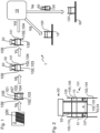
- the 1 shows a schematic of a process sequence 1 for producing an outer packaging 120 open on one side, in particular an RSC outer packaging.
- a pre-glued cardboard blank 100 is removed from a magazine 2 and drawn up in a box shape in a first method step Va.
- the mounted carton blank 101 has a typical box shape with four bottom flaps 102 at the bottom box opening and four top flaps 105 at the top box opening.
- the mounted carton blank 101 has two small inner bottom flaps 103 lying opposite one another and two outer bottom flaps 104 lying opposite one another and offset between the small inner bottom flaps 103 (cf. 2 ). With the reference number 107 fold lines for bottom flaps 102 and top flaps 105 are shown in dashed lines.
- the bottom flaps 102 and the top flaps 105 are each still arranged in a plane relative to a respective adjoining side wall 109 of the carton blank 101, so that the latter has two opposite openings.
- a second method step Vb the mounted carton blank 101 is gripped by a gripping device 50 (in 2 shown in more detail), the gripper arms 52 reaching through the top opening of the carton blank 101 and sucking in the inner bottom flaps 102 folded in by 90°.
- a third method step Vc in the embodiment of the method shown here, an adhesive 130 is applied at least in regions to the outsides of the folded-in inner bottom flaps 103.
- a fourth method step Vd the outer bottom flaps 104 are folded in using a closure module 10, which is described in detail below, and the Outer packaging 120 formed in this way, which is open on one side, is fed to further processing via a transport device 16 assigned to the closure module 10 .
- the outer packaging 120 formed in this way, which is open on one side can be transferred to a further transport unit 60 in a method step Ve by means of the gripping device 50 for further processing. Provision can optionally be made here for the outer packaging 120, which is open on one side, to be rotated by 90° during the transfer.
- the 2 shows a schematic representation of a gripping device 50 for a mounted carton blank 101.
- the mounted carton blank 101 is shown in particular cut open in order to be able to show the gripping device 50, which is partially arranged inside the mounted carton blank 101, better.
- the mounted carton blank 101 is held on the inner side walls 110 of the box shape 101 by holding elements 51 .
- the mounted carton blank 101 is held by setting a distance A between the free ends of the holding elements 51 which corresponds to the spacing between the opposite inner side walls 110 of the mounted carton blank 101 .
- the holding elements 51 are on two gripper arms 52 of the gripping device 50 arranged.
- the two gripper arms 52 can be moved relative to one another and in particular can be moved towards one another or away from one another.
- the gripper arms 52 can be rotatable and/or variable in length.
- the gripper arms 52 are positioned relatively close to one another, so that a distance between the free ends of the holding elements 51 is less than the distance A between the opposite inner side walls 110 of the carton blank 101 to be picked up.
- the gripper arms 52 of the gripping device 50 are inserted from above through the upper opening of the mounted carton blank 101 until the lower free ends 53 of the gripper arms 52 are arranged level with the fold lines 107 of the bottom flaps 102.
- the lower free ends 53 of the gripper arms 52 each have suction devices 54 in order to fold the small inner bottom flaps 103 upwards by suction.
- the gripper arms 52 are moved so far apart that the free ends of the holding elements 51 are braced between the inner side walls 110 of the mounted carton blank 101 in order to hold the carton blank 101 in place.
- the gripper arms 52 can also first be inserted so far into the carton blank 101 that the suction elements 54 are arranged below the fold lines 107 . After grasping the small inner bottom flaps 103, the gripper arms 52 are pulled upwards again until the free ends 53 of the gripper arms 52 are level with the fold lines 107 of the bottom flaps 102. In this way, the inner bottom flaps 103 can be folded inwards.
- the suction elements 54 can be designed to be rotatable and/or pivotable and/or variable in length or similar, in order to grasp the small inner bottom flaps 103 and fold them upwards until they are at a 90° angle to the side walls 110 and the outer bottom flaps 104 are arranged.
- the holding elements 51 are variable in length, so that a length between the free end of the respective holding element 51 and the end of the holding element 51 fastened to the gripper arm 52 can be adjusted.
- a relative distance between the gripper arms 52 does not necessarily have to be changed. Under certain circumstances, it can be useful to set a relative distance between the gripper arms 52 and changing the length of the holding members 51 in order to hold the carton blank 101 drawn open.
- the mounted carton blank 101 is held by the gripping device 50 on the one hand by clamping the side walls 109 and on the other hand by sucking in the small inner bottom flaps 103 .
- the cardboard blank 101 is pulled up over a connecting link, with the inner bottom flaps 102 being folded inwards by 90°.
- the suction elements 54 attach to the folded-in inner bottom flaps 102, as a result of which the drawn-up carton blank 101 is additionally held.
- the 3 shows an isolated adjustment mechanism 11 of an embodiment of a closure module 10 for closing the outer bottom flaps 104 of an outer packaging.
- the adjustment mechanism 11 comprises a plurality of pressure strips 20 which are designed in particular as pressure slides.
- a plurality of pressure strips 20 are preferably mechanically coupled to one another in such a way that they can be driven together.
- the drive system 30 comprises two parallel, circulating toothed belts 31, 32. These are coupled to a servo drive 33 via a common drive shaft 35, so that the toothed belts 31, 32 are driven synchronously.
- the pressure strips 20 are each arranged between the toothed belts 31, 32 via fastening devices 21 and are connected to them in such a way that a movement of the toothed belts 31, 32 causes a corresponding movement of the pressure strips 20.
- Pressure strips 20 lying next to one another are arranged alternately on the upper strand 31o, 32o and lower strand 31u, 32u of the toothed belts 31, 32.
- the pressure strips 20a are each arranged on the upper run 31o, 32o of the toothed belts 31, 32 and the pressure strips 20b are each arranged on the lower run 31u, 32u of the toothed belts 31, 32.
- the alternating arrangement causes adjacent pressure strips 20a, 20b, driven by the movement of the toothed belts 31, 32, to move in opposite directions.
- Two adjacent pressure strips 20a, 20b form what is known as a pair of slides 25, which, driven by the toothed belts 31, 32, perform a linear opening or closing movement.
- a according 2 Prepared carton blank 101 with small inner bottom flaps 103 already folded inwards, on the outside of which an adhesive 130 may be applied (cf. 1 ). Pressure strips 20a, 20b is formed (cf. also 4 ). The outer bottom flaps 104 hang down between the pressure strips 20a, 20b of a pair of slides 25. The carton blank 101 is arranged in particular between the pressure strips 20a, 20b of the pair of slides 25 in such a way that the outer bottom flaps 104 are aligned hanging parallel to the pressure strips 20a, 20b. The pressure strips 20a, 20b of a pair of slides 25 are now moved toward one another.
- This closing movement folds the outer bottom flaps 104 upwards and presses them against the outer sides of the small inner bottom flaps 103 that have been folded in.
- the servo drive 33 is controlled via a control device 40 in such a way that the upper strand 31o, 32o of the toothed belt 31, 32 moves in a first direction of movement B1. Accordingly, the pressure strips 20a arranged on the upper strand 31o, 32o move in the direction of movement B1 and the pressure strips 20b arranged on the lower strand 31u, 32u move counter to the direction of movement B1.
- Spring-loaded pressure plates 23 are mounted on the pressure strips 20 .
- the pressure strips 20a, 20b of a pair of slides 25 are pushed together, these generate an even pressure which acts on the outside of the respective outer bottom flaps 104.
- the outer bottom flaps 104 are thus pressed against the small inner bottom flaps 103 which have already been folded in and are held by the suction means 54 of the gripping device 50, as a result of which a pressure is felt on the outside of the inner bottom flaps 103 applied adhesive, such as glue, evenly distributed and excess glue can be squeezed out if necessary.
- the Figures 4 to 6 12 schematically show side representations of a part of the adjustment mechanism 11 of a closure module 10 according to FIG 3 in a first working state AZ1 ( 4 ), a transition state AZÜ ( figure 5 ) and a second working state AZ2 ( 6).
- 7 shows the adjustment mechanism 11 of a closure module 10 according to FIG Figures 3 and 4 from above in a first working state AZ1, while 8 according to the adjustment mechanism of a locking module Figures 3 and 6 shows from above in a second working state AZ2.
- the two pressure strips 20a, 20b of a pair of slides 25 are spaced apart in such a way that according to 2 Prepared carton blank 101 with small inner bottom flaps 103 already folded inwards is arranged between two pressure strips 20a, 20b of a pair of slides 25 by gripping device 50 in such a way that the folded-in small inner bottom flaps 103 are essentially in a horizontal plane H, which is approximately horizontal Corresponds to the plane formed by the tops 22 of the pressure strips 20a, 20b.
- the outer bottom flaps 104 hang down between the pressure strips 20a, 20b of the pair of slides 25.
- the 9 shows a perspective view of a closure module 10 with an adjustment mechanism 11 according to FIG 3 for closing the outer bottom flaps 104 of an outer packaging 101 (cf. 2 ), and the 10 shows the one below the adjustment mechanism 11 (cf. 3 ) arranged substructure 12 of the closure module 10 according to 9 .
- the pressure strips 20a, 20b of the slide pairs 25 can be positioned at different points on the upper strand 31o, 32o or lower strand 31u, 32u of the toothed belt 31, 32 of the drive system via the fastening devices 21.
- an arrangement in the area of a glue receiving device is advantageous for removing excess glue that escapes between the small inner bottom flaps 103 and the outer bottom flaps 104 when the outer bottom flaps 104 are closed and pressed against the small inner bottom flaps 103 .
- a transport device 16 for further transport of the outer packaging 120 which is now closed at the bottom (cf. figures 1 and 6 ) arranged.
- the outer packaging is fed to a packaging module, for example, in which the outer packaging is filled with items and, if necessary, sealed.
- the outer packaging which is closed on the bottom by the infeed movement of the pressure strips 20a, 20b of a pair of slides 25, can be released by moving the pressure strips 20a, 20b of the pair of slides 25 away from one another and can be set down on the transport device 16 arranged below the adjustment mechanism 11.
- First guide elements 17 , 18 can be provided on the substructure 12 so that the outer packaging does not tip over or twist when it is placed on the transport device 16 .
- second guide elements 24 can be arranged to support the pressure strips 20a, 20b.
- the outer packaging is guided on the transport unit 16 by lateral guide elements 18 .
- the first guide elements 17 arranged above the lateral guide elements 18 are designed in particular as an inclined surface in order to advantageously reduce the impact energy of the outer packaging on the transport device 16 and thereby prevent the outer packaging from falling over.
- the entire process flow, in particular the further transport of the outer packaging to the subsequent packaging modules, can be optimized in terms of time by directly depositing the outer packaging, which is closed on the bottom side.
- a closure module 10 For folding the outer bottom flaps 104 of a carton blank 101 by an infeed movement of two sliding elements or pressure bars 20a, 20b, a closure module 10 can also be used without a substructure 12 according to FIG 10 be used.
- a closure module 10 has a base 12 according to FIG Figures 9 and 10 up
- the outer packaging which is closed on the bottom side
- the bottom side The closed outer packaging can be brought into a desired orientation by rotating the gripping device 50, for example the outer packaging can be rotated by 90°.
- the bottom-closed outer packaging is set down on a transport device 16 of the lower part 12 of a closure module 10, it can also be provided that, after the outer bottom flaps 104 have been closed and pressed on, the bottom-closed outer packaging is first rotated, in particular a 90° rotation, before the Outer packaging is deposited onto the transport device 16 by a movement of the pressure strips 20a, 20b of the pair of slides 25 directed away from one another.
- This rotation can also be brought about in particular by a rotation of the gripping device 50 holding the outer packaging during the entire folding and closing process.
- the bottom-sealed outer packaging can now be filled directly with articles, for example bottles, with an outer packaging combined article combinations, for example baskets, trays, shrink packs, multipacks, filled with bottles or the like in a downstream packaging module. Provision can also be made for dividing elements, for example compartments, to be inserted into the outer packaging first, and then for the articles to be filled.
- a large number of outer packages can be processed at the same time with the aid of a single drive.
- the number of outer packages that can be closed in parallel corresponds to the number of slide pairs 25 that are coupled to one another in terms of drive technology. Since only one drive has to be controlled, such a closure module 10 can be put into operation easily. In particular, such a closure module 10 can be quickly and easily adapted to a new product when there is a product change. For example, the respective speed and the respective time interval at which the toothed belts 31, 32 are driven must be set via the control device in order to set the appropriate spacing of the pressure strips 20a, 20b of the pairs of slides 25 before the outer bottom flaps 104 of the outer packaging 101 are closed.
- the necessary spacing results from a width of the outer packaging 101 to be arranged between the pressure strips 20a, 20b of the respective pair of slides 25.
- the closing speed can be adapted to the respective outer packaging 101.
Landscapes
- Making Paper Articles (AREA)
- Supplying Of Containers To The Packaging Station (AREA)
- Container Filling Or Packaging Operations (AREA)
Claims (14)
- Dispositif de manipulation destiné à fermer des languettes de fond extérieures (104) d'un emballage supplémentaire ayant des lignes de pliage (107) pour des languettes de fond intérieures (103) et des languettes de fond extérieures (104), ledit dispositif de manipulation comprenant:- au moins un dispositif de maintien (50) pour une découpe de carton (101) déployée ayant des lignes de pliage (107) pour des languettes de fond intérieures (103) et des languettes de fond extérieures (104),- dans lequel le dispositif de maintien (50) est conçu pour replier et maintenir les languettes de fond intérieures (103) de la découpe de carton (101),- au moins un dispositif d'application d'agent adhésif et- un module de fermeture (10) comprenant au moins une unité de fermeture (25) destinée à fermer les languettes de fond extérieures (104) d'une découpe de carton (101) déployée maintenue par le dispositif de maintien (50),- dans lequel l'unité de fermeture (25) comprend au moins deux éléments coulissants (20) conçus de manière à être déplaçables l'un par rapport à l'autre dans un plan horizontal,
caractérisé par le fait que- les éléments coulissants (20) comprennent des éléments d'appui à ressort (23). - Dispositif de manipulation selon la revendication 1, dans lequel le dispositif de maintien (50) comprend des premiers dispositifs de maintien (51) pour maintenir par serrage des surfaces latérales intérieures (110) de la découpe de carton (101) déployée, et dans lequel le dispositif de maintien (50) comprend au moins un deuxième dispositif de maintien pour replier vers l'intérieur et/ou pour maintenir ladite au moins une languette de fond intérieure (103) de la découpe de carton (101) déployée, en particulier des dispositifs d'aspiration (54) pour replier vers l'intérieur et/ou pour maintenir les languettes de fond intérieures (103) de la découpe de carton (101) déployée.
- Dispositif de manipulation selon la revendication 1 ou 2, dans lequel le module de fermeture (10) comprend une pluralité d'unités de fermeture (25) comportant chacune deux éléments coulissants (20) conçus de manière à être déplaçables l'un par rapport à l'autre dans un plan horizontal, dans lequel les éléments coulissants (20) de toutes les unités de fermeture (25) sont disposés en particulier dans un plan horizontal commun.
- Dispositif de manipulation selon la revendication 3, dans lequel au moins les éléments coulissants (20) d'une unité de fermeture (25) sont agencés de manière couplée en mouvement sur un mécanisme d'entraînement (30) commun, dans lequel les éléments coulissants (20) de l'unité de fermeture (25) permettent d'effectuer respectivement un mouvement opposé, ou dans lequel les éléments coulissants (20) de toutes les unités de fermeture (25) sont agencés de manière couplée en mouvement sur un mécanisme d'entraînement (30) commun, dans lequel les éléments coulissants (20) d'une unité de fermeture (25) permettent d'effectuer respectivement un mouvement opposé et dans lequel les éléments coulissants (20) directement adjacents d'unités de fermeture (25) adjacentes permettent d'effectuer respectivement un mouvement opposé.
- Dispositif de manipulation selon la revendication 3 ou 4, dans lequel le mécanisme d'entraînement (30) comprend au moins un moyen de transport circulant qui est agencé sur un moyen d'entraînement et qui comprend un brin supérieur (31o, 32o) et un brin inférieur (31u, 32u), dans lequel l'un des éléments coulissants (20) d'une unité de fermeture (25) est agencé sur le brin supérieur (31o, 32o) du moyen de transport et dans lequel l'autre élément coulissant (20) de l'unité de fermeture (25) est agencé sur le brin inférieur (31u, 32u) du moyen de transport.
- Dispositif de manipulation selon la revendication 5, dans lequel le mécanisme d'entraînement (30) comprend deux moyens de transport qui sont guidés en parallèle et sont agencés sur le moyen d'entraînement par l'intermédiaire d'un arbre d'entraînement (35) commun, dans lequel les éléments coulissants (20) sont agencés chacun entre les deux moyens de transport et sont fixés chacun aux deux moyens de transport, en particulier dans lequel les éléments coulissants (20) sont agencés alternativement de part et d'autre sur le brin supérieur (31o, 32o) des deux moyens de transport ou de part et d'autre sur le brin inférieur (31u, 32u) des deux moyens de transport.
- Dispositif de manipulation selon la revendication 5 ou 6, dans lequel le moyen d'entraînement est une servotransmission (33) et/ou dans lequel ledit au moins un moyen de transport circulant est une courroie crantée (31, 32).
- Dispositif de manipulation selon la revendication 4, dans lequel les éléments coulissants (20) de toutes les unités de fermeture (25) présentent chacun un propre entraînement, dans lequel les entraînements sont commandés par le biais d'un dispositif de commande (40) de telle sorte que respectivement les éléments coulissants (20) d'une unité de fermeture (25) sont déplaçables chacun dans des directions opposées et/ou que des éléments coulissants (20) respectivement adjacents d'unités de fermeture (25) adjacentes sont déplaçables chacun dans des directions opposées.
- Dispositif de manipulation selon l'une quelconque des revendications précédentes, dans lequel un dispositif de transport (16) destiné à évacuer des découpes de carton (120) fermées au fond est disposé en dessous de ladite au moins une unité de fermeture (25), dans lequel la découpe de carton (120) fermée au fond peut être déposée sur le dispositif de transport (16) par un mouvement des éléments coulissants (20) de l'unité de fermeture (25) respective, qui est dirigé de manière à les écarter, dans lequel en particulier des éléments de guidage (17, 18, 24) sont prévus pour le dépôt contrôlé de la découpe de carton (120) fermée au fond sur le dispositif de transport (16).
- Dispositif de manipulation selon l'une quelconque des revendications précédentes, dans lequel un dispositif d'évacuation destiné à évacuer de l'agent adhésif (130) excédentaire est associé à ladite au moins une unité de fermeture (25).
- Procédé de fermeture de languettes de fond extérieures (104) d'un emballage supplémentaire ayant des lignes de pliage (107) pour des languettes de fond intérieures (103) et des languettes de fond extérieures (104), ledit procédé comprenant au moins les étapes suivantes consistant à:- saisir une découpe de carton (101) déployée, dans lequel les languettes de fond intérieures (103) sont repliés en même temps ou ensuite le long des lignes de pliage (107) de 90° à peu près vers l'intérieur de la forme de boîte de la découpe de carton déployée;- agencer la découpe de carton (101) entre deux éléments coulissants (20) d'une unité de fermeture (25);- fermer ou bien replier les languettes de fond extérieures (104) de la découpe de carton (101) par un mouvement d'avance des deux éléments coulissants (20) de l'unité de fermeture (25) dans un plan horizontal,- appliquer, à l'aide d'un dispositif d'application d'agent adhésif, un agent adhésif sur les faces extérieures de languettes de fond intérieures repliées ou au niveau du point de contact des deux languettes de fond extérieures repliées,caractérisé par le fait que
les éléments coulissants (20) comprennent des éléments d'appui à ressort (23). - Procédé selon la revendication 11, en utilisant un dispositif de manipulation selon l'une quelconque des revendications 1 à 10.
- Procédé selon la revendication 11 ou 12, dans lequel, avant de fermer ou bien de replier les languettes de fond extérieures (104), un agent adhésif (130) est appliqué au moins par zones sur les surfaces latérales extérieures des languettes de fond intérieures (103) repliées, et/ou dans lequel, après avoir fermé ou bien replié les languettes de fond extérieures (104), un agent adhésif (130) est appliqué au moins par zones sur un point de contact des deux languettes de fond extérieures (104) repliées.
- Procédé selon l'une quelconque des revendications 11 à 13, dans lequel les languettes de fond intérieures (103) repliées sont pressés contre les languettes de fond extérieures (104) repliées par un autre léger mouvement dirigé vers le bas d'une découpe de carton (120) maintenant fermée au fond, et/ou dans lequel la découpe de carton (120) fermée au fond est transportée vers d'autres modules d'emballage pour un traitement ultérieur, dans lequel la découpe de carton (120) fermée au fond peut être tournée de 90° à peu près avant que celle-ci ne soit amenée au traitement ultérieur, et/ou dans lequel, afin de déposer la découpe de carton (120) fermée au fond sur un dispositif de transport (16), les deux éléments coulissants (20) de l'unité de fermeture (25) sont écartés à l'intérieur du plan horizontal.
Applications Claiming Priority (2)
| Application Number | Priority Date | Filing Date | Title |
|---|---|---|---|
| DE102017201842.9A DE102017201842A1 (de) | 2017-02-06 | 2017-02-06 | Handhabungsvorrichtung und Verfahren zum Verschließen von äußeren Bodenlaschen einer Umverpackung |
| PCT/EP2018/050183 WO2018141498A2 (fr) | 2017-02-06 | 2018-01-04 | Dispositif de manipulation et procédé de fermeture de languettes de fond extérieures d'un suremballage |
Publications (3)
| Publication Number | Publication Date |
|---|---|
| EP3576932A2 EP3576932A2 (fr) | 2019-12-11 |
| EP3576932B1 true EP3576932B1 (fr) | 2023-06-21 |
| EP3576932C0 EP3576932C0 (fr) | 2023-06-21 |
Family
ID=60972219
Family Applications (1)
| Application Number | Title | Priority Date | Filing Date |
|---|---|---|---|
| EP18700395.9A Active EP3576932B1 (fr) | 2017-02-06 | 2018-01-04 | Dispositif de manipulation et procédé de fermeture de languettes de fond extérieures d'un suremballage |
Country Status (4)
| Country | Link |
|---|---|
| EP (1) | EP3576932B1 (fr) |
| CN (1) | CN210590752U (fr) |
| DE (1) | DE102017201842A1 (fr) |
| WO (1) | WO2018141498A2 (fr) |
Families Citing this family (3)
| Publication number | Priority date | Publication date | Assignee | Title |
|---|---|---|---|---|
| CN109606782B (zh) * | 2018-12-27 | 2024-01-09 | 重庆市灵龙自动化设备有限公司 | 具有开合翻盖功能的硬质包装盒传送线 |
| CN112644082B (zh) * | 2020-12-29 | 2023-04-07 | 易程融创信息科技有限公司 | 用于生产纸盒的设备 |
| CN114559699B (zh) * | 2022-03-22 | 2023-10-20 | 广西巨星医疗器械有限公司 | 一种医用胶片盒自动折盒的方法 |
Family Cites Families (13)
| Publication number | Priority date | Publication date | Assignee | Title |
|---|---|---|---|---|
| DE1025323B (de) | 1953-01-07 | 1958-02-27 | Hesser Ag Maschf | Einrichtung zum Herstellen des Bodenverschlusses von Faltschachteln mit eingedruecktem Boden, insbesondere an Hochleistungsverpackungsmaschinen |
| FR1513487A (fr) * | 1967-01-03 | 1968-02-16 | Dispositif pour le montage et la fermeture des caisses carton par collage | |
| US3748972A (en) | 1971-11-01 | 1973-07-31 | Emhart Corp | Method and apparatus for erecting and bottom sealing cartons |
| US4012996A (en) * | 1975-05-09 | 1977-03-22 | Stolmar Corporation | Apparatus for folding and compression of corrugated container blanks |
| NL7600650A (nl) | 1976-01-22 | 1977-07-26 | Nuts Chocoladefabriek Bv | Werkwijze voor het met behulp van lijm sluiten van gevulde dozen. |
| DE2937385C2 (de) | 1979-09-15 | 1981-10-01 | Siemens AG, 1000 Berlin und 8000 München | Vorrichtung zum Einfalten der Bodenklappen von Faltschachteln |
| DE3301237A1 (de) | 1983-01-15 | 1984-08-09 | Focke & Co, 2810 Verden | Verfahren und vorrichtung zum verschliessen von kartons |
| DE8533313U1 (fr) * | 1985-11-27 | 1990-03-01 | Robert Bosch Gmbh, 7000 Stuttgart, De | |
| SE505154C2 (sv) * | 1993-02-17 | 1997-07-07 | Tetra Laval Holdings & Finance | Förpackningsmaskin med en ändlös transportör och utbytbara maskinmoduler |
| DE4325181C2 (de) | 1993-07-27 | 1997-04-10 | Schrutt Gmbh | Vorrichtung zum Falten und Verschließen der Stirnwände von Faltkartons |
| JPH08119239A (ja) * | 1994-10-31 | 1996-05-14 | Sony Corp | カートン処理システム及びカートン処理方法 |
| DE19905867A1 (de) | 1999-02-12 | 2000-08-17 | Altonaer Wellpappenfab Gmbh | Verpackung, Verfahren zu ihrer Herstellung und Vorrichtung zur Durchführung des Verfahrens |
| JP5841086B2 (ja) * | 2013-02-28 | 2016-01-06 | 株式会社フジキカイ | 箱詰機における製函装置 |
-
2017
- 2017-02-06 DE DE102017201842.9A patent/DE102017201842A1/de active Pending
-
2018
- 2018-01-04 CN CN201890000335.5U patent/CN210590752U/zh active Active
- 2018-01-04 WO PCT/EP2018/050183 patent/WO2018141498A2/fr active Application Filing
- 2018-01-04 EP EP18700395.9A patent/EP3576932B1/fr active Active
Also Published As
| Publication number | Publication date |
|---|---|
| EP3576932A2 (fr) | 2019-12-11 |
| EP3576932C0 (fr) | 2023-06-21 |
| WO2018141498A2 (fr) | 2018-08-09 |
| DE102017201842A1 (de) | 2018-08-09 |
| WO2018141498A3 (fr) | 2018-10-25 |
| WO2018141498A4 (fr) | 2018-12-20 |
| CN210590752U (zh) | 2020-05-22 |
Similar Documents
| Publication | Publication Date | Title |
|---|---|---|
| EP3439970B1 (fr) | Procédé et dispositif permettant de former des corps d'emballage ouverts d'un côté, constitués d'enveloppes d'emballage ouvertes des deux côtés | |
| EP0460374B1 (fr) | Procédé et dispositif d'emballage d'objets dans une boîte pliable | |
| DE4035352C2 (de) | Vorrichtung zum Herstellen von Schachteln mit Klappdeckel und Kragen und zum Befüllen dieser Schachteln | |
| EP3187427B1 (fr) | Dispositif et procédé destinés à saisir et à transporter des cartons rsc | |
| EP3576932B1 (fr) | Dispositif de manipulation et procédé de fermeture de languettes de fond extérieures d'un suremballage | |
| EP0983940A1 (fr) | Dispositif pour emballer des objets ou des piles | |
| EP3326795B1 (fr) | Dispositif de traitement d'un matériau d'emballage et procédé | |
| DE102017201830A1 (de) | Faltvorrichtung, Verpackungsanlage für Artikel und Verfahren zum Falten von Seitenlaschen von Kartonumverpackungen | |
| WO2015124396A1 (fr) | Dispositif et procédé de pré-pliage d'enveloppes d'emballage | |
| EP3649052B1 (fr) | Procédé et dispositif de fabrication de corps d'emballage ouverts d'un côté à l'aide d'un préhenseur oscillant | |
| EP3585602B1 (fr) | Arrangement de manipulation et de pliage et procédé de dépliage et d'introduction d'un élément de subdivision dans un suremballage | |
| EP3372513B1 (fr) | Dispositif de manipulation d'articles et procédé d'échange d'au moins un module de transport et d'au moins un dispositif de travail dudit module | |
| WO2020216564A1 (fr) | Procédé et dispositif de dépliage au moins partiel d'enveloppes d'emballage pliées à plat | |
| EP3459867B1 (fr) | Procédé et machine de fabrication de sachets en feuille remplis, scellés longitudinalement et transversalement, d'une bande de feuille non conservant la forme | |
| WO2020151934A1 (fr) | Procédé et dispositif de pliage au moins partiel d'enveloppes d'emballage pliées à plat | |
| DE2612458C2 (de) | Verfahren zum Aufrichten und Verkleben von zunächst ebenen, mit Falzlinien und Klebeflächen versehenen Kartonzuschnitten und zum Verpacken von Behältern in den entstehenden Kartons | |
| WO2017182164A1 (fr) | Procédé et dispositif permettant la manutention de marchandises de détail déplacées les unes derrière les autres | |
| EP3564137B1 (fr) | Procédé et dispositif de fermeture d'emballages groupés en carton | |
| WO2019234104A1 (fr) | Arrangement avec station de façonnage pour former des corps d'emballage ouverts d'un côté | |
| DE4230927A1 (de) | Verfahren und vorrichtung zum aufrichten eines mit handgriffverriegelung versehenen verpackungskartons | |
| WO2024002658A1 (fr) | Procédé et dispositif pour former des corps d'emballage ouverts d'un côté, constitués de structures latérales d'emballage ouvertes des deux côtés | |
| DE2456701A1 (de) | Verfahren und vorrichtung zum entnehmen von packungszuschnitten oder dergleichen fuer die tabakverarbeitende industrie | |
| EP0878401A1 (fr) | Système et procédé de préhension pour ériger et monter des emballages de transport |
Legal Events
| Date | Code | Title | Description |
|---|---|---|---|
| STAA | Information on the status of an ep patent application or granted ep patent |
Free format text: STATUS: UNKNOWN |
|
| STAA | Information on the status of an ep patent application or granted ep patent |
Free format text: STATUS: THE INTERNATIONAL PUBLICATION HAS BEEN MADE |
|
| PUAI | Public reference made under article 153(3) epc to a published international application that has entered the european phase |
Free format text: ORIGINAL CODE: 0009012 |
|
| STAA | Information on the status of an ep patent application or granted ep patent |
Free format text: STATUS: REQUEST FOR EXAMINATION WAS MADE |
|
| 17P | Request for examination filed |
Effective date: 20190716 |
|
| AK | Designated contracting states |
Kind code of ref document: A2 Designated state(s): AL AT BE BG CH CY CZ DE DK EE ES FI FR GB GR HR HU IE IS IT LI LT LU LV MC MK MT NL NO PL PT RO RS SE SI SK SM TR |
|
| AX | Request for extension of the european patent |
Extension state: BA ME |
|
| DAV | Request for validation of the european patent (deleted) | ||
| DAX | Request for extension of the european patent (deleted) | ||
| STAA | Information on the status of an ep patent application or granted ep patent |
Free format text: STATUS: EXAMINATION IS IN PROGRESS |
|
| 17Q | First examination report despatched |
Effective date: 20220607 |
|
| GRAP | Despatch of communication of intention to grant a patent |
Free format text: ORIGINAL CODE: EPIDOSNIGR1 |
|
| STAA | Information on the status of an ep patent application or granted ep patent |
Free format text: STATUS: GRANT OF PATENT IS INTENDED |
|
| INTG | Intention to grant announced |
Effective date: 20221007 |
|
| GRAJ | Information related to disapproval of communication of intention to grant by the applicant or resumption of examination proceedings by the epo deleted |
Free format text: ORIGINAL CODE: EPIDOSDIGR1 |
|
| STAA | Information on the status of an ep patent application or granted ep patent |
Free format text: STATUS: EXAMINATION IS IN PROGRESS |
|
| INTC | Intention to grant announced (deleted) | ||
| GRAP | Despatch of communication of intention to grant a patent |
Free format text: ORIGINAL CODE: EPIDOSNIGR1 |
|
| STAA | Information on the status of an ep patent application or granted ep patent |
Free format text: STATUS: GRANT OF PATENT IS INTENDED |
|
| INTG | Intention to grant announced |
Effective date: 20230127 |
|
| GRAS | Grant fee paid |
Free format text: ORIGINAL CODE: EPIDOSNIGR3 |
|
| GRAA | (expected) grant |
Free format text: ORIGINAL CODE: 0009210 |
|
| STAA | Information on the status of an ep patent application or granted ep patent |
Free format text: STATUS: THE PATENT HAS BEEN GRANTED |
|
| AK | Designated contracting states |
Kind code of ref document: B1 Designated state(s): AL AT BE BG CH CY CZ DE DK EE ES FI FR GB GR HR HU IE IS IT LI LT LU LV MC MK MT NL NO PL PT RO RS SE SI SK SM TR |
|
| REG | Reference to a national code |
Ref country code: CH Ref legal event code: EP |
|
| REG | Reference to a national code |
Ref country code: DE Ref legal event code: R096 Ref document number: 502018012514 Country of ref document: DE |
|
| REG | Reference to a national code |
Ref country code: AT Ref legal event code: REF Ref document number: 1580640 Country of ref document: AT Kind code of ref document: T Effective date: 20230715 |
|
| REG | Reference to a national code |
Ref country code: IE Ref legal event code: FG4D Free format text: LANGUAGE OF EP DOCUMENT: GERMAN |
|
| U01 | Request for unitary effect filed |
Effective date: 20230628 |
|
| U07 | Unitary effect registered |
Designated state(s): AT BE BG DE DK EE FI FR IT LT LU LV MT NL PT SE SI Effective date: 20230705 |
|
| REG | Reference to a national code |
Ref country code: LT Ref legal event code: MG9D |
|
| PG25 | Lapsed in a contracting state [announced via postgrant information from national office to epo] |
Ref country code: NO Free format text: LAPSE BECAUSE OF FAILURE TO SUBMIT A TRANSLATION OF THE DESCRIPTION OR TO PAY THE FEE WITHIN THE PRESCRIBED TIME-LIMIT Effective date: 20230921 |
|
| PG25 | Lapsed in a contracting state [announced via postgrant information from national office to epo] |
Ref country code: RS Free format text: LAPSE BECAUSE OF FAILURE TO SUBMIT A TRANSLATION OF THE DESCRIPTION OR TO PAY THE FEE WITHIN THE PRESCRIBED TIME-LIMIT Effective date: 20230621 Ref country code: HR Free format text: LAPSE BECAUSE OF FAILURE TO SUBMIT A TRANSLATION OF THE DESCRIPTION OR TO PAY THE FEE WITHIN THE PRESCRIBED TIME-LIMIT Effective date: 20230621 Ref country code: GR Free format text: LAPSE BECAUSE OF FAILURE TO SUBMIT A TRANSLATION OF THE DESCRIPTION OR TO PAY THE FEE WITHIN THE PRESCRIBED TIME-LIMIT Effective date: 20230922 |
|
| PG25 | Lapsed in a contracting state [announced via postgrant information from national office to epo] |
Ref country code: SK Free format text: LAPSE BECAUSE OF FAILURE TO SUBMIT A TRANSLATION OF THE DESCRIPTION OR TO PAY THE FEE WITHIN THE PRESCRIBED TIME-LIMIT Effective date: 20230621 |
|
| PG25 | Lapsed in a contracting state [announced via postgrant information from national office to epo] |
Ref country code: ES Free format text: LAPSE BECAUSE OF FAILURE TO SUBMIT A TRANSLATION OF THE DESCRIPTION OR TO PAY THE FEE WITHIN THE PRESCRIBED TIME-LIMIT Effective date: 20230621 |
|
| PG25 | Lapsed in a contracting state [announced via postgrant information from national office to epo] |
Ref country code: IS Free format text: LAPSE BECAUSE OF FAILURE TO SUBMIT A TRANSLATION OF THE DESCRIPTION OR TO PAY THE FEE WITHIN THE PRESCRIBED TIME-LIMIT Effective date: 20231021 |
|
| U20 | Renewal fee paid [unitary effect] |
Year of fee payment: 7 Effective date: 20231219 |
|
| PG25 | Lapsed in a contracting state [announced via postgrant information from national office to epo] |
Ref country code: SM Free format text: LAPSE BECAUSE OF FAILURE TO SUBMIT A TRANSLATION OF THE DESCRIPTION OR TO PAY THE FEE WITHIN THE PRESCRIBED TIME-LIMIT Effective date: 20230621 Ref country code: SK Free format text: LAPSE BECAUSE OF FAILURE TO SUBMIT A TRANSLATION OF THE DESCRIPTION OR TO PAY THE FEE WITHIN THE PRESCRIBED TIME-LIMIT Effective date: 20230621 Ref country code: RO Free format text: LAPSE BECAUSE OF FAILURE TO SUBMIT A TRANSLATION OF THE DESCRIPTION OR TO PAY THE FEE WITHIN THE PRESCRIBED TIME-LIMIT Effective date: 20230621 Ref country code: IS Free format text: LAPSE BECAUSE OF FAILURE TO SUBMIT A TRANSLATION OF THE DESCRIPTION OR TO PAY THE FEE WITHIN THE PRESCRIBED TIME-LIMIT Effective date: 20231021 Ref country code: ES Free format text: LAPSE BECAUSE OF FAILURE TO SUBMIT A TRANSLATION OF THE DESCRIPTION OR TO PAY THE FEE WITHIN THE PRESCRIBED TIME-LIMIT Effective date: 20230621 Ref country code: CZ Free format text: LAPSE BECAUSE OF FAILURE TO SUBMIT A TRANSLATION OF THE DESCRIPTION OR TO PAY THE FEE WITHIN THE PRESCRIBED TIME-LIMIT Effective date: 20230621 |
|
| PG25 | Lapsed in a contracting state [announced via postgrant information from national office to epo] |
Ref country code: PL Free format text: LAPSE BECAUSE OF FAILURE TO SUBMIT A TRANSLATION OF THE DESCRIPTION OR TO PAY THE FEE WITHIN THE PRESCRIBED TIME-LIMIT Effective date: 20230621 |
|
| REG | Reference to a national code |
Ref country code: DE Ref legal event code: R097 Ref document number: 502018012514 Country of ref document: DE |
|
| PLBE | No opposition filed within time limit |
Free format text: ORIGINAL CODE: 0009261 |
|
| STAA | Information on the status of an ep patent application or granted ep patent |
Free format text: STATUS: NO OPPOSITION FILED WITHIN TIME LIMIT |