EP3569552B1 - Steuervorrichtung eines ver-/entriegelungsorgans eines öffnungsflügels auf einem rahmen, wie einem riegel, und diese umfassendes schloss - Google Patents
Steuervorrichtung eines ver-/entriegelungsorgans eines öffnungsflügels auf einem rahmen, wie einem riegel, und diese umfassendes schloss Download PDFInfo
- Publication number
- EP3569552B1 EP3569552B1 EP19170908.8A EP19170908A EP3569552B1 EP 3569552 B1 EP3569552 B1 EP 3569552B1 EP 19170908 A EP19170908 A EP 19170908A EP 3569552 B1 EP3569552 B1 EP 3569552B1
- Authority
- EP
- European Patent Office
- Prior art keywords
- notched
- bolt
- sector
- lock
- operating arm
- Prior art date
- Legal status (The legal status is an assumption and is not a legal conclusion. Google has not performed a legal analysis and makes no representation as to the accuracy of the status listed.)
- Active
Links
Images






Classifications
-
- B—PERFORMING OPERATIONS; TRANSPORTING
- B66—HOISTING; LIFTING; HAULING
- B66B—ELEVATORS; ESCALATORS OR MOVING WALKWAYS
- B66B13/00—Doors, gates, or other apparatus controlling access to, or exit from, cages or lift well landings
- B66B13/02—Door or gate operation
- B66B13/14—Control systems or devices
- B66B13/16—Door or gate locking devices controlled or primarily controlled by condition of cage, e.g. movement or position
Definitions
- One of these devices consists of having an electromagnet whose movable ferromagnetic core is coupled to the member to be controlled which may be a bolt according to the chosen application example.
- the electromagnet can be controlled by an electrical signal depending on the position of a cabin or platform of the lifting device.
- Another drawback of this electromagnet device lies in the fact that during the entire time the car is immobilized on a floor (for example at night), the coil is permanently powered in order to keep the bolt in the opening position of the landing door, which is likely to cause heating which can lead to rapid destruction of the coil.
- An aim of the present invention is to propose a landing door lock for a lifting device which in particular overcomes the aforementioned drawbacks.
- a lock according to claim 1 is provided.
- the rotational force generated by the rotating actuator such as an electric motor, and transmitted by this gear train, is designed such that the actuating unit can be advantageously used in the lock housing both for a lock whose bolt extends from the left side of the housing and for a lock whose bolt extends from the right side of the housing, i.e. without requiring substantial modifications to the control device or additional components depending on the opening side of the door. This results in a saving of components for the lock, regardless of the locking/unlocking side of the door equipped with it.
- said notched sector may have the shape of a circular half-crown comprising a central portion covered with radial notches and two terminal portions which are respectively fixed to two wings extending at right angles a vertex of said operating arm mounted on said fixed pivot axis, said operating arm may have a general T shape whose free end opposite said vertex is connected to said member, such that said terminal portions of said notched sector form a substantially isosceles triangle with said free end of said operating arm.
- this semi-circle shape for the curved rack whose teeth forming these radial notches (i.e. teeth whose summits or summit edges extend along the direction of a radius of the semi-circle passing through the fixed pivot axis) are provided at the center of this rack thus allows, via its terminal portions, the assembly integral in rotation with the operating arm and this rack such that the curved rack and the arm with which it is provided admit as a common plane of symmetry the median longitudinal plane of the arm.
- said notched sector is in one piece, said central portion covered with radial notches being formed in one piece with said terminal portions which are respectively fixed to said wings of said operating arm by two fixing elements with axes parallel to said fixed pivot axis.
- These fixing elements are, for example, mounted in such a way as to connect the operating arm to the notched sector in a non-deformable manner (i.e. without any degree of freedom of the arm relative to the notched sector).
- said terminal portions are provided with oblong holes in arcs of a circle, to allow movement of said fixing elements in said oblong holes when, without using said actuator or said at least one pinion, rotation is imparted to said fixed pivot axis by an external emergency key causing rotation of said operating arm and translation of said member, for reversibly obtaining said retracted unlocking position.
- these oblong holes thus allow the unlocking of the organ by the operating arm using this key when the actuator, such as an electric motor, is blocked.
- This sliding assembly of the notched covering in the central portion of the support can be obtained by an assembly of the arc-shaped rib type forming a slide on the lower face of the covering. (opposite its upper face showing the notches) / groove in an arc of a circle formed on the upper face opposite the central portion of the support, or vice versa.
- this sliding assembly with lateral stop allows, in addition to the aforementioned unlocking by the emergency key, a rotation of the operating arm thanks to the rotation generated by the actuator and transmitted to and by the curved rack, then a return to the initial position by means of the thrust exerted by the return means applied against the locking/unlocking member.
- the stop between the notched coating and the sector support is used for driving by the motor, while the distance from this stop is used during unlocking by the key.
- said notched sector further comprises return means comprising two pre-stressed helical compression springs, which are respectively mounted on both sides and bearing against said notched covering, so as to allow an over-torque exerted on said notched covering causing, by relative sliding, a momentary displacement in an arc of a circle of said notched covering relative to said sector support then a return to the initial position when said over-torque is cancelled, one of said pre-stressed springs being compressed and the other relaxed when said unlocking position is obtained.
- return means comprising two pre-stressed helical compression springs, which are respectively mounted on both sides and bearing against said notched covering, so as to allow an over-torque exerted on said notched covering causing, by relative sliding, a momentary displacement in an arc of a circle of said notched covering relative to said sector support then a return to the initial position when said over-torque is cancelled, one of said pre-stressed springs being compressed and the other relaxed when said unlocking position is
- this variant thus makes it possible not only to obtain this over-torque with a reversible curvilinear movement of the notched coating on the sector support, but also a rotational drive of the operating arm even when the actuator, such as an electric motor, is blocked, it being specified that this curvilinear sliding compresses one of the two pre-stressed springs while relaxing the other.
- said notched sector further comprises separable connecting means of the clip and drive pin type between said notched covering and said sector support, said connecting means being adapted to maintain said notched covering in movement according to an arc of a circle relative to said sector support by relative sliding and for obtaining a disengagement of said operating arm relative to said notched sector, in particular during an over-torque exerted on said notched coating, or for obtaining the rotation of said operating arm and the translation of said member in said unlocking position, by a rotation directly imparted to said fixed pivot axis by said emergency key.
- these clip and stud connection means make it possible to use the emergency key to slide in a curvilinear manner with “unclipping” (i.e. separation of the clips) the notched covering on the sector support, when the actuator, such as an electric motor, is blocked.
- said fixed pivot axis in said retracted unlocking position, can be located substantially at an equal distance from one end of said return means mounted against said first wall of said housing and from an axially external end opposite said member mounted flush with said second wall of said housing.
- said fixed pivot axis is further perpendicular to a plane containing said translation axis and the longitudinal axis of symmetry of the operating arm.
- said rotation actuator comprises a stepper electric motor coupled to control electronics and optionally also to a reduction group.
- stepper electric motor specifically in combination with the notched sector according to the invention makes it possible to obtain a higher final torque on the operating arm for a lower electrical consumption than with a conventional electric motor.
- the actuator such as an electric motor, preferably a stepper motor
- the actuator can be activated from a signal acting positively or negatively on its power supply so as to modify the position of the locking/unlocking member, it being recalled that the aforementioned emergency key and the independent return force exerted by the return means applied against this member during a power cut to the actuator also make it possible to modify the position of this member.
- the notched sector 16 is in one piece, having the shape of a circular half-crown comprising a central portion 17 covered with radial notches 17a and two terminal portions 18 which are respectively fixed, by two fixing elements 19 with axes parallel to the fixed axis P, to two wings 12a extending at right angles a vertex 12b of the arm 12 mounted on the fixed axis P.
- the arm 12 has the shape of a symmetrical T whose free end 12c opposite the vertex 12b is coupled to the bolt 5, so that in this for example the terminal portions 18 form an isosceles triangle with the free end 12c of the arm 12.
- the fixed axis P is materialized by a pivot P' of generally prismatic geometry of triangular section truncated at its corners by flats, in this exemplary embodiment.
- the terminal portions 18 of the notched sector 16 they are raised relative to its central portion 17 in the direction of the fixed axis P via shoulders, and each wing 12a of the arm 12 comprises two legs 12aa superimposed and spaced from each other in this direction of the fixed axis P which are adapted to grip a terminal portion 18 for the through-mounting of a fixing element 19.
- Each fixing element 19 thus passes through orifices opposite the two legs 12aa of each wing 12a and the terminal portion 18 which they grip.
- a meshing via the electric motor 13 of the pinion 15 on the notched sector 16 causes a rotation of the latter around the fixed axis P and a pivoting of the arm 12 on this fixed axis P for the reversible translation control of the bolt 5 from its extended position of the figure 1 to its retracted position of the figure 2 (in which the axially external end 5b of the bolt 5 is substantially flush with the second wall 4 of the housing 2), and vice versa.
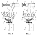
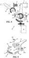
- the 10' control device of the Figures 6-9 corresponds to a variant of the example of Figures 1-5 still according to the first embodiment of the invention, which differs from this example only in that the raised terminal portions 18' of the single-piece notched sector 16' respectively have two oblong holes 18a in arcs of a circle symmetrical to each other adapted to receive in curvilinear sliding the fixing elements 19 (visible in the figure) figure 9 and constituted as in Figures 1-6 of two tubular pins 19 provided in this example with collars 19a and locking rings 19b).
- the fixed axis P can be operated directly in the direction of the arrow M by means of an emergency key 20 when the motor 13 is blocked, for example, in order to rotate the arm 12 in the direction allowing the bolt 5 to be moved from its extended position to its retracted position of the figure 8 .
- the bolt 5 can be unlocked without rotating the motor 13 or the pinion 15.
- the notched covering 118 is able to slide in a curvilinear manner in the central portion 116a of the support 117 via a rib 118b in an arc of a circle formed on a lower face of the covering 118 cooperating in sliding with a corresponding groove 117b of the upper face of the central portion 116a.
- This mutual abutment on one side of the notched sector 116, of the covering 118 and of the support 117, allows rotation of the arm 12 by the motor 13 then a return to the initial position by means of the thrust F generated by the spring 11 of the bolt 5 and also, without rotation of the motor 13 or of the pinion 15 (i.e. in particular when the motor 13 is blocked), to directly maneuver the fixed axis P in the direction of the arrow M by means of an emergency key 20 to rotate the arm 12 in the direction allowing the bolt 5 to be brought from its extended position to its retracted position of the figure 12 .
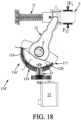
- the control device 110' according to the variant of the second mode of the invention visible in Figures 14-18 is essentially distinguished from the example of Figures 10-13a , in that (see Figures 16-17 ) the notched sector 116' in two parts 117 and 118 further comprises two pre-stressed helical compression springs 119 and 120 respectively mounted on both sides and bearing against the notched covering 118.
- This assembly not only allows rotational drive of the arm 12 but also allows an over-torque on the notching 118a of the covering 118, with a momentary curvilinear sliding of the covering 118 on the support 117 secured to the arm 12, then a return to the initial position when the over-torque is cancelled.
- FIG 16 illustrates the usefulness of the two parts 117 and 118 and of the springs 119 and 120 if the motor 13 is blocked. Indeed, when the bolt 5 is unlocked with the emergency key 20 rotating the fixed axis P in the required direction, the covering 118 slides on the support 117 by compressing one spring 119 and relaxing the other spring 120.
- FIG 18 further illustrates the usefulness of the two parts 117 and 118 and of the springs 119 and 120 if the translation of the bolt 5 is temporarily or permanently blocked in the locked or semi-locked position by an external action (see force F1 exerted on the bolt 5), one of the springs 120 compressing while the other spring 119 relaxes proportionally.
- the control device 110" according to the other variant of the second mode of the invention visible in Figures 19-22a is essentially distinguished from the variant of Figures 14-18 , in that (see Figures 22-22a ) the notched sector 116" in two parts 117 and 118 further comprises separable connecting means of the clip type 121 and drive pins 122 between the notched covering 118 and the sector support 117. As visible in the figure 22a , the clips 121 are arranged on either side of the rib 118b on the lower face of the notched covering 118.
- FIG 21 illustrates the usefulness of the two parts 117 and 118 and the clips/nipples 121 if the motor 13 is blocked. Indeed, when the bolt 5 is unlocked with the emergency key 20, the covering 118 slides relative to the sector support 117 by unclipping (i.e. by separation of the clips 121 and nipples 122).
- the notched covering 118 is held in curvilinear sliding on the sector support 117 secured to the arm 12 by means of the clips 121 and pins 122, then allowing the arm 12 to be disengaged relative to the notched covering 118, for example during an over-torque.
Landscapes
- Engineering & Computer Science (AREA)
- Automation & Control Theory (AREA)
- Lock And Its Accessories (AREA)
Claims (9)
- Riegel (1) für die Schachttür einer Aufzugsanlage, wobei der Riegel (1) folgendes umfasst:ein Gehäuse (2),einen Riegelbolzen (5) zum Verriegeln/Entriegeln der Schachttür undeine Steuereinrichtung (10, 10', 110, 110', 110") des Verriegelungs-/Entriegelungsbolzens (5),wobei das Gerät folgendes umfasst:- Betätigungsmittel (10a) des Riegels (5), die dafür ausgelegt sind, ihn reversibel in Translation entlang einer Translationsachse (X) von einer ausgefahrenen Verriegelungsposition in eine zurückgezogene Entriegelungsposition relativ zum Gehäuse (2) des Riegels (1) zu bringen, wobei die Betriebsmittel umfassen:* Rückstellmittel (11), die den Riegelbolzen (5) in die ausgefahrene Verriegelungsposition zurückbringen und die zur Unterstützung entlang der Translationsachse zwischen einer ersten Wand (3) des Gehäuses (2) und einem axial inneren Ende (5a) des Riegelbolzens (5), wobei die Rückstellmittel beispielsweise eine Schraubendruckfeder (11) umfassen, und* einen Betätigungsarm (12), der mit dem Riegelbolzen (5) verbunden ist, so dass eine Drehung des Betätigungsarms (12) eine Verschiebung des Bolzens (5) durch eine zweite Wand (4) des Gehäuses (2) gegenüber der ersten Wand bewirkt (3), wobei der Betätigungsarm (12) schwenkbar um eine feste Schwenkachse (P) relativ zum Gehäuse (2) montiert ist, welcher orthogonal ist und die Translationsachse (X) nicht schneidet; und- eine Betätigungseinheit (10b), die durch ein elektrisches geeignetes Signal aktivierbar ist den Manövrierarm zu drehen (12), wobei die Betätigungseinheit folgendes umfasst:* einen rotierenden Aktuator (13), der beispielsweise einen Elektromotor (13) umfasst, und* Übertragungsmittel (14) der Drehung des Aktuators (13) auf den Betätigungsarm (12), wobei die Übertragungsmittel (14) einen Getriebezug umfassen, der mindestens ein Zahnrad (15) umfasst, das mit einem Getriebewellenausgang (13a) des Aktuators gekoppelt ist (13),Welches dadurch gekennzeichnet ist das- die Übertragungsmittel (14) einen gezahnten Sektor (16, 16', 116, 116', 116") umfassen, der eine gekrümmte Zahnstange bildet, mit der das mindestens ein Zahnrad (15) kämmt, wobei der gezahnte Sektor schwenkbar um die feste Schwenkachse montiert ist (P),- der Betätigungsarm (12) ist fest mit dem verzahnten Sektor drehbar gelagert, so dass der Eingriff des letzteren auf mindestens ein Zahnrad (15) auf dem verzahnten Sektor eine Drehung dieses Sektors um die feste Achse (P) und eine Drehung des Betätigungsarms (12) auf der festen Achse (P) zur translatorischen Steuerung des Bolzens bewirkt (5),- die feste Schwenkachse (P) parallel und in wesentlich selbem Abstand von der ersten Wand (3) und der zweiten Wand (4) des Gehäuses vorgesehen ist, während die Translationsachse (X) des Bolzens (5) senkrecht zur ersten Wand und zur zweiten Wand vorgesehen ist.
- Riegel (1) entsprechend Anspruch 1, bei dem der verzahnte Sektor (16, 16', 116, 116', 116") die Form einer kreisförmigen Halbkrone hat, die einen abgedeckten Mittelabschnitt (17, 116a) mit radialen Zähnen aufweist (17a, 118a).
- Riegel (1) entsprechend Anspruch 2, bei dem der verzahnte Sektor (16, 16') einteilig ist, wobei der mit radialen Zähnen (17a) bedeckte Mittelabschnitt (17) einteilig mit den Endabschnitten (18) des verzahnten Sektors 18') ausgebildet ist die jeweils an dem Betätigungsarm (12) durch zwei Befestigungselemente (19) befestigt sind deren Achsen parallel zur festen Schwenkachse (P) ausgerichtet sind.
- Riegel (1) entsprechend Anspruch 3, bei dem die Endabschnitte (18') mit kreisbogenförmigen Langlöchern (18a) versehen sind, um eine Bewegung der Befestigungselemente (19) in den Langlöchern zu ermöglichen, wenn ohne Verwendung des Aktuators (13) oder eines Zahnrades (15) auf der festen Drehachse (P) durch einen externen Notentriegelungs-Schlüssel (20) eine Drehung ausgeübt wird welche die Drehung des Betätigungsarms (12) und die Translation des Bolzens bewirkt (5), um die zurückgezogene Entriegelungsposition reversibel zu erreichen.
- Riegel (1) entsprechend Anspruch 2, bei dem der verzahnte Sektor (116, 116', 116") aus mindestens zwei Teilen besteht, bestehend aus:- eine Sektor-Halterung (117), die sowohl den Mittelabschnitt (116a) als auch die Endabschnitte (116b) des verzahnten Sektors bildet und an dem Betätigungsarm (12) befestigt ist, und- eine abnehmbare, verzahnte Abdeckung (118) mit den gennaten radialen Zähnen (118a), die verschiebbar im Mittelteil des Trägers angebracht ist, so dass sie an einem Ende des Mittelteils anliegt.
- Riegel (1) entsprechend Anspruch 5, bei dem der verzahnte Sektor (116') außerdem Rückstellmittel aufweist, die aus zwei vorgespannten Schraubendruckfedern (119 und 120) bestehen, die jeweils auf beiden Seiten angebracht sind und gegen die verzahnte Abdeckung stützen (118), um ein zusätzliches Drehmoment zu ermöglichen, das auf die verzahnte Abdeckung ausgeübt wird und durch relatives Gleiten eine vorübergehende Bewegung in einem Kreisbogen der verzahnten Abdeckung relativ zum Sektor-Träger (117) und dann eine Rückkehr in die Ausgangsposition der genannten Sektor-Halterung (117) bewirkt wenn das Überdrehmoment aufgehoben wird, wobei eine der vorgespannten Federn (120) zusammengedrückt und die andere (119) entspannt wird, wenn die Entriegelungsposition erreicht wird.
- Riegel (1) entsprechend Anspruch 5, bei dem der verzahnte Sektor (116") außerdem trennbare Verbindungsmittel vom Typ Clip (121) und Stifte (122) zwischen der verzahnten Abdeckung (118) und dem genannten Sektor aufweist (117), wobei die Verbindungsmittel (121 und 122) dafür ausgelegt sind, die Bewegung der verzahnten Abdeckung entlang eines Kreisbogens relativ zur Sektor-Stütze durch relatives Verschieben aufrechtzuerhalten und ein Entkuppeln des Betätigungsarms (12) relativ zu dem verzahnten Sektor zu erreichen, insbesondere während eines übermäßigen Drehmoments, das auf die verzahnte Abdeckung ausgeübt wird, oder um die Drehung des Betätigungsarms und die Verschiebung des Bolzens (5) in die Entriegelungsposition durch die Drehung zu erreichen, die direkt auf der festen Schwenkachse (P) durch den Notentriegelungsschlüssel ausgeübt ist. (20).
- Riegel (1) entsprechend einem der vorhergehenden Ansprüche, bei dem sich die feste Schwenkachse (P) in der zurückgezogenen Entriegelungsposition im Wesentlichen in gleichem Abstand von einem Ende (11a) der an der ersten Wand des Gehäuses montierten Rückholeinrichtung (11) befindet (3) (2) und eines axialen äußeren Endes (5b) gegenüber dem Riegelbolzen (5), das bündig mit der zweiten Wand (4) des Gehäuses abschließt.
- Riegel (1) entsprechend einem der vorhergehenden Ansprüche, wobei der Drehantrieb (13) einen Schrittmotor (13) beinhaltet, welcher mit einer Steuerungs-Elektronik und optional weiterhin mit einer Untersetzungsgruppe gekoppelt ist.
Applications Claiming Priority (1)
| Application Number | Priority Date | Filing Date | Title |
|---|---|---|---|
| FR1853742A FR3080639B1 (fr) | 2018-04-27 | 2018-04-27 | Dispositif de commande d'un organe de verrouillage/ deverrouillage d'un ouvrant sur un dormant, tel qu'un pene, et serrure l'incorporant |
Publications (2)
| Publication Number | Publication Date |
|---|---|
| EP3569552A1 EP3569552A1 (de) | 2019-11-20 |
| EP3569552B1 true EP3569552B1 (de) | 2024-08-21 |
Family
ID=63036100
Family Applications (1)
| Application Number | Title | Priority Date | Filing Date |
|---|---|---|---|
| EP19170908.8A Active EP3569552B1 (de) | 2018-04-27 | 2019-04-24 | Steuervorrichtung eines ver-/entriegelungsorgans eines öffnungsflügels auf einem rahmen, wie einem riegel, und diese umfassendes schloss |
Country Status (2)
| Country | Link |
|---|---|
| EP (1) | EP3569552B1 (de) |
| FR (1) | FR3080639B1 (de) |
Family Cites Families (5)
| Publication number | Priority date | Publication date | Assignee | Title |
|---|---|---|---|---|
| DE185968C (de) * | 1906-01-25 | 1907-05-16 | ||
| US1050648A (en) * | 1912-04-12 | 1913-01-14 | Losh O Harbaugh | Automatic device for elevators. |
| US1557857A (en) * | 1925-01-03 | 1925-10-20 | Warner Elevator Mfg Company | Safety locking apparatus for elevators |
| DE3836693C2 (de) * | 1988-10-28 | 1996-01-25 | Fliether Karl Gmbh & Co | Treibstangenschloß |
| FR3048252B1 (fr) * | 2016-02-25 | 2020-03-06 | Assa Abloy Cote Picarde | Ensemble de serrure a tringles d'actionnement independantes |
-
2018
- 2018-04-27 FR FR1853742A patent/FR3080639B1/fr active Active
-
2019
- 2019-04-24 EP EP19170908.8A patent/EP3569552B1/de active Active
Also Published As
| Publication number | Publication date |
|---|---|
| EP3569552A1 (de) | 2019-11-20 |
| FR3080639B1 (fr) | 2022-07-29 |
| FR3080639A1 (fr) | 2019-11-01 |
Similar Documents
| Publication | Publication Date | Title |
|---|---|---|
| FR3078991A1 (fr) | Commande d’ouverture à actionneur linéaire pour véhicule automobile. | |
| EP3456579A1 (de) | Gleitschiene für fahrzeugsitz, und fahrzeugsitz, der eine solche gleitschiene umfasst | |
| FR2503233A1 (fr) | Dispositif de reglage de position, notamment installation combinee de manoeuvre de vitre et de verrouillage central de porte de vehicule automobile | |
| FR3023865A1 (fr) | Ensemble de poignee pour vehicule automobile et ouvrant comprenant un tel ensemble de poignee | |
| EP3405633A1 (de) | Externe öffnungssteuerung eines kraftfahrzeugs | |
| FR3032424A1 (fr) | Dispositif de manoeuvre d'au moins une trappe d'un aeronef comprenant une poignee de commande | |
| FR2654767A1 (fr) | Mecanisme de commande d'ouverture d'une portiere de vehicule automobile et portiere le comportant. | |
| FR3001488A1 (fr) | Ensemble pour verrouiller et deverrouiller un ouvrant articule a un dormant | |
| EP2622157B1 (de) | Griff mit zwei hebeln für eine fahrzeugtür | |
| FR2920461A1 (fr) | Dispositif de maintien en position d'ouverture stable d'un ouvrant de vehicule automobile, en particulier d'un capot avant | |
| FR2958962A1 (fr) | Commande d'ouverture interieure d'un ouvrant de vehicule automobile et vehicule automobile equipee d'une telle commande. | |
| FR2601992A1 (fr) | Groupe modulaire serrure cylindrique-barillet | |
| WO2020094688A1 (fr) | Dispositif d'ouverture d'urgence d'une porte d'aéronef, à débrayage rotatif | |
| FR2816977A1 (fr) | Serrure a commande electrique | |
| EP3569552A1 (de) | Steuervorrichtung eines ver-/entriegelungsorgans eines öffnungsflügels auf einem rahmen, wie einem riegel, und diese umfassendes schloss | |
| EP0989266B1 (de) | Schloss mit automatischer Entriegelung beim Öffnen | |
| FR2880852A1 (fr) | Boite a gants de vehicule automobile | |
| EP0906997A1 (de) | Verriegelungsvorrichtung mit einem nockenbetätigten Übertragungselement | |
| EP0243214B1 (de) | Verriegelungsvorrichtung verwendbar als Diebstahlsicherung für ein elektrisches Kraftfahrzeugtürschloss und übereinstimmendes Schloss | |
| EP0837208B1 (de) | Treibstangenbremsevorrichtung und Schiebeflügel mit einer solchen Vorrichtung | |
| WO2012052533A1 (fr) | Dispositif de commande pour système de verrouillage de porte de véhicule | |
| FR2941544A3 (fr) | Dispositif d'actionnement manuel pour deux organes de vehicule automobile devant etre actionnes alternativement | |
| FR2753224A1 (fr) | Serrure electromagnetique pour porte a ouverture telecommandee | |
| EP4257781B1 (de) | Türgriff für eine lastkraftwagentür | |
| EP1657380B1 (de) | Antriebsvorrichtung für ein Flügelschliessmechanismus mittels Eindrückhandhabe und damit ausgerüstetem Flügel |
Legal Events
| Date | Code | Title | Description |
|---|---|---|---|
| PUAI | Public reference made under article 153(3) epc to a published international application that has entered the european phase |
Free format text: ORIGINAL CODE: 0009012 |
|
| STAA | Information on the status of an ep patent application or granted ep patent |
Free format text: STATUS: THE APPLICATION HAS BEEN PUBLISHED |
|
| AK | Designated contracting states |
Kind code of ref document: A1 Designated state(s): AL AT BE BG CH CY CZ DE DK EE ES FI FR GB GR HR HU IE IS IT LI LT LU LV MC MK MT NL NO PL PT RO RS SE SI SK SM TR |
|
| AX | Request for extension of the european patent |
Extension state: BA ME |
|
| STAA | Information on the status of an ep patent application or granted ep patent |
Free format text: STATUS: REQUEST FOR EXAMINATION WAS MADE |
|
| 17P | Request for examination filed |
Effective date: 20200520 |
|
| RBV | Designated contracting states (corrected) |
Designated state(s): AL AT BE BG CH CY CZ DE DK EE ES FI FR GB GR HR HU IE IS IT LI LT LU LV MC MK MT NL NO PL PT RO RS SE SI SK SM TR |
|
| STAA | Information on the status of an ep patent application or granted ep patent |
Free format text: STATUS: EXAMINATION IS IN PROGRESS |
|
| 17Q | First examination report despatched |
Effective date: 20210111 |
|
| GRAP | Despatch of communication of intention to grant a patent |
Free format text: ORIGINAL CODE: EPIDOSNIGR1 |
|
| STAA | Information on the status of an ep patent application or granted ep patent |
Free format text: STATUS: GRANT OF PATENT IS INTENDED |
|
| INTG | Intention to grant announced |
Effective date: 20240311 |
|
| GRAS | Grant fee paid |
Free format text: ORIGINAL CODE: EPIDOSNIGR3 |
|
| GRAA | (expected) grant |
Free format text: ORIGINAL CODE: 0009210 |
|
| STAA | Information on the status of an ep patent application or granted ep patent |
Free format text: STATUS: THE PATENT HAS BEEN GRANTED |
|
| AK | Designated contracting states |
Kind code of ref document: B1 Designated state(s): AL AT BE BG CH CY CZ DE DK EE ES FI FR GB GR HR HU IE IS IT LI LT LU LV MC MK MT NL NO PL PT RO RS SE SI SK SM TR |
|
| REG | Reference to a national code |
Ref country code: GB Ref legal event code: FG4D Free format text: NOT ENGLISH |
|
| REG | Reference to a national code |
Ref country code: CH Ref legal event code: EP |
|
| REG | Reference to a national code |
Ref country code: DE Ref legal event code: R096 Ref document number: 602019057272 Country of ref document: DE |
|
| REG | Reference to a national code |
Ref country code: IE Ref legal event code: FG4D Free format text: LANGUAGE OF EP DOCUMENT: FRENCH |
|
| P01 | Opt-out of the competence of the unified patent court (upc) registered |
Free format text: CASE NUMBER: APP_53077/2024 Effective date: 20240923 |
|
| REG | Reference to a national code |
Ref country code: LT Ref legal event code: MG9D |
|
| REG | Reference to a national code |
Ref country code: NL Ref legal event code: MP Effective date: 20240821 |
|
| PG25 | Lapsed in a contracting state [announced via postgrant information from national office to epo] |
Ref country code: NO Free format text: LAPSE BECAUSE OF FAILURE TO SUBMIT A TRANSLATION OF THE DESCRIPTION OR TO PAY THE FEE WITHIN THE PRESCRIBED TIME-LIMIT Effective date: 20241121 |
|
| REG | Reference to a national code |
Ref country code: AT Ref legal event code: MK05 Ref document number: 1715346 Country of ref document: AT Kind code of ref document: T Effective date: 20240821 |
|
| PG25 | Lapsed in a contracting state [announced via postgrant information from national office to epo] |
Ref country code: PT Free format text: LAPSE BECAUSE OF FAILURE TO SUBMIT A TRANSLATION OF THE DESCRIPTION OR TO PAY THE FEE WITHIN THE PRESCRIBED TIME-LIMIT Effective date: 20241223 Ref country code: NL Free format text: LAPSE BECAUSE OF FAILURE TO SUBMIT A TRANSLATION OF THE DESCRIPTION OR TO PAY THE FEE WITHIN THE PRESCRIBED TIME-LIMIT Effective date: 20240821 Ref country code: FI Free format text: LAPSE BECAUSE OF FAILURE TO SUBMIT A TRANSLATION OF THE DESCRIPTION OR TO PAY THE FEE WITHIN THE PRESCRIBED TIME-LIMIT Effective date: 20240821 Ref country code: PL Free format text: LAPSE BECAUSE OF FAILURE TO SUBMIT A TRANSLATION OF THE DESCRIPTION OR TO PAY THE FEE WITHIN THE PRESCRIBED TIME-LIMIT Effective date: 20240821 Ref country code: GR Free format text: LAPSE BECAUSE OF FAILURE TO SUBMIT A TRANSLATION OF THE DESCRIPTION OR TO PAY THE FEE WITHIN THE PRESCRIBED TIME-LIMIT Effective date: 20241122 |
|
| PG25 | Lapsed in a contracting state [announced via postgrant information from national office to epo] |
Ref country code: BG Free format text: LAPSE BECAUSE OF FAILURE TO SUBMIT A TRANSLATION OF THE DESCRIPTION OR TO PAY THE FEE WITHIN THE PRESCRIBED TIME-LIMIT Effective date: 20240821 |
|
| PG25 | Lapsed in a contracting state [announced via postgrant information from national office to epo] |
Ref country code: LV Free format text: LAPSE BECAUSE OF FAILURE TO SUBMIT A TRANSLATION OF THE DESCRIPTION OR TO PAY THE FEE WITHIN THE PRESCRIBED TIME-LIMIT Effective date: 20240821 |
|
| PG25 | Lapsed in a contracting state [announced via postgrant information from national office to epo] |
Ref country code: IS Free format text: LAPSE BECAUSE OF FAILURE TO SUBMIT A TRANSLATION OF THE DESCRIPTION OR TO PAY THE FEE WITHIN THE PRESCRIBED TIME-LIMIT Effective date: 20241221 Ref country code: AT Free format text: LAPSE BECAUSE OF FAILURE TO SUBMIT A TRANSLATION OF THE DESCRIPTION OR TO PAY THE FEE WITHIN THE PRESCRIBED TIME-LIMIT Effective date: 20240821 |
|
| PG25 | Lapsed in a contracting state [announced via postgrant information from national office to epo] |
Ref country code: HR Free format text: LAPSE BECAUSE OF FAILURE TO SUBMIT A TRANSLATION OF THE DESCRIPTION OR TO PAY THE FEE WITHIN THE PRESCRIBED TIME-LIMIT Effective date: 20240821 |
|
| PG25 | Lapsed in a contracting state [announced via postgrant information from national office to epo] |
Ref country code: ES Free format text: LAPSE BECAUSE OF FAILURE TO SUBMIT A TRANSLATION OF THE DESCRIPTION OR TO PAY THE FEE WITHIN THE PRESCRIBED TIME-LIMIT Effective date: 20240821 Ref country code: RS Free format text: LAPSE BECAUSE OF FAILURE TO SUBMIT A TRANSLATION OF THE DESCRIPTION OR TO PAY THE FEE WITHIN THE PRESCRIBED TIME-LIMIT Effective date: 20241121 |
|
| PG25 | Lapsed in a contracting state [announced via postgrant information from national office to epo] |
Ref country code: RS Free format text: LAPSE BECAUSE OF FAILURE TO SUBMIT A TRANSLATION OF THE DESCRIPTION OR TO PAY THE FEE WITHIN THE PRESCRIBED TIME-LIMIT Effective date: 20241121 Ref country code: PT Free format text: LAPSE BECAUSE OF FAILURE TO SUBMIT A TRANSLATION OF THE DESCRIPTION OR TO PAY THE FEE WITHIN THE PRESCRIBED TIME-LIMIT Effective date: 20241223 Ref country code: PL Free format text: LAPSE BECAUSE OF FAILURE TO SUBMIT A TRANSLATION OF THE DESCRIPTION OR TO PAY THE FEE WITHIN THE PRESCRIBED TIME-LIMIT Effective date: 20240821 Ref country code: NO Free format text: LAPSE BECAUSE OF FAILURE TO SUBMIT A TRANSLATION OF THE DESCRIPTION OR TO PAY THE FEE WITHIN THE PRESCRIBED TIME-LIMIT Effective date: 20241121 Ref country code: NL Free format text: LAPSE BECAUSE OF FAILURE TO SUBMIT A TRANSLATION OF THE DESCRIPTION OR TO PAY THE FEE WITHIN THE PRESCRIBED TIME-LIMIT Effective date: 20240821 Ref country code: LV Free format text: LAPSE BECAUSE OF FAILURE TO SUBMIT A TRANSLATION OF THE DESCRIPTION OR TO PAY THE FEE WITHIN THE PRESCRIBED TIME-LIMIT Effective date: 20240821 Ref country code: IS Free format text: LAPSE BECAUSE OF FAILURE TO SUBMIT A TRANSLATION OF THE DESCRIPTION OR TO PAY THE FEE WITHIN THE PRESCRIBED TIME-LIMIT Effective date: 20241221 Ref country code: HR Free format text: LAPSE BECAUSE OF FAILURE TO SUBMIT A TRANSLATION OF THE DESCRIPTION OR TO PAY THE FEE WITHIN THE PRESCRIBED TIME-LIMIT Effective date: 20240821 Ref country code: GR Free format text: LAPSE BECAUSE OF FAILURE TO SUBMIT A TRANSLATION OF THE DESCRIPTION OR TO PAY THE FEE WITHIN THE PRESCRIBED TIME-LIMIT Effective date: 20241122 Ref country code: FI Free format text: LAPSE BECAUSE OF FAILURE TO SUBMIT A TRANSLATION OF THE DESCRIPTION OR TO PAY THE FEE WITHIN THE PRESCRIBED TIME-LIMIT Effective date: 20240821 Ref country code: ES Free format text: LAPSE BECAUSE OF FAILURE TO SUBMIT A TRANSLATION OF THE DESCRIPTION OR TO PAY THE FEE WITHIN THE PRESCRIBED TIME-LIMIT Effective date: 20240821 Ref country code: BG Free format text: LAPSE BECAUSE OF FAILURE TO SUBMIT A TRANSLATION OF THE DESCRIPTION OR TO PAY THE FEE WITHIN THE PRESCRIBED TIME-LIMIT Effective date: 20240821 Ref country code: AT Free format text: LAPSE BECAUSE OF FAILURE TO SUBMIT A TRANSLATION OF THE DESCRIPTION OR TO PAY THE FEE WITHIN THE PRESCRIBED TIME-LIMIT Effective date: 20240821 |
|
| REG | Reference to a national code |
Ref country code: DE Ref legal event code: R082 Ref document number: 602019057272 Country of ref document: DE Representative=s name: PLASSERAUD IP GMBH, DE |
|
| PG25 | Lapsed in a contracting state [announced via postgrant information from national office to epo] |
Ref country code: RO Free format text: LAPSE BECAUSE OF FAILURE TO SUBMIT A TRANSLATION OF THE DESCRIPTION OR TO PAY THE FEE WITHIN THE PRESCRIBED TIME-LIMIT Effective date: 20240821 Ref country code: DK Free format text: LAPSE BECAUSE OF FAILURE TO SUBMIT A TRANSLATION OF THE DESCRIPTION OR TO PAY THE FEE WITHIN THE PRESCRIBED TIME-LIMIT Effective date: 20240821 Ref country code: SM Free format text: LAPSE BECAUSE OF FAILURE TO SUBMIT A TRANSLATION OF THE DESCRIPTION OR TO PAY THE FEE WITHIN THE PRESCRIBED TIME-LIMIT Effective date: 20240821 |
|
| PG25 | Lapsed in a contracting state [announced via postgrant information from national office to epo] |
Ref country code: EE Free format text: LAPSE BECAUSE OF FAILURE TO SUBMIT A TRANSLATION OF THE DESCRIPTION OR TO PAY THE FEE WITHIN THE PRESCRIBED TIME-LIMIT Effective date: 20240821 |
|
| PG25 | Lapsed in a contracting state [announced via postgrant information from national office to epo] |
Ref country code: CZ Free format text: LAPSE BECAUSE OF FAILURE TO SUBMIT A TRANSLATION OF THE DESCRIPTION OR TO PAY THE FEE WITHIN THE PRESCRIBED TIME-LIMIT Effective date: 20240821 |
|
| PG25 | Lapsed in a contracting state [announced via postgrant information from national office to epo] |
Ref country code: IT Free format text: LAPSE BECAUSE OF FAILURE TO SUBMIT A TRANSLATION OF THE DESCRIPTION OR TO PAY THE FEE WITHIN THE PRESCRIBED TIME-LIMIT Effective date: 20240821 Ref country code: SK Free format text: LAPSE BECAUSE OF FAILURE TO SUBMIT A TRANSLATION OF THE DESCRIPTION OR TO PAY THE FEE WITHIN THE PRESCRIBED TIME-LIMIT Effective date: 20240821 |
|
| REG | Reference to a national code |
Ref country code: DE Ref legal event code: R097 Ref document number: 602019057272 Country of ref document: DE |
|
| PLBE | No opposition filed within time limit |
Free format text: ORIGINAL CODE: 0009261 |
|
| STAA | Information on the status of an ep patent application or granted ep patent |
Free format text: STATUS: NO OPPOSITION FILED WITHIN TIME LIMIT |
|
| PGFP | Annual fee paid to national office [announced via postgrant information from national office to epo] |
Ref country code: DE Payment date: 20250411 Year of fee payment: 7 |
|
| 26N | No opposition filed |
Effective date: 20250522 |
|
| PG25 | Lapsed in a contracting state [announced via postgrant information from national office to epo] |
Ref country code: SE Free format text: LAPSE BECAUSE OF FAILURE TO SUBMIT A TRANSLATION OF THE DESCRIPTION OR TO PAY THE FEE WITHIN THE PRESCRIBED TIME-LIMIT Effective date: 20240821 |
|
| REG | Reference to a national code |
Ref country code: CH Ref legal event code: H13 Free format text: ST27 STATUS EVENT CODE: U-0-0-H10-H13 (AS PROVIDED BY THE NATIONAL OFFICE) Effective date: 20251125 |
|
| PG25 | Lapsed in a contracting state [announced via postgrant information from national office to epo] |
Ref country code: LU Free format text: LAPSE BECAUSE OF NON-PAYMENT OF DUE FEES Effective date: 20250424 |
|
| PG25 | Lapsed in a contracting state [announced via postgrant information from national office to epo] |
Ref country code: MC Free format text: LAPSE BECAUSE OF FAILURE TO SUBMIT A TRANSLATION OF THE DESCRIPTION OR TO PAY THE FEE WITHIN THE PRESCRIBED TIME-LIMIT Effective date: 20240821 |
|
| GBPC | Gb: european patent ceased through non-payment of renewal fee |
Effective date: 20250424 |
|
| REG | Reference to a national code |
Ref country code: BE Ref legal event code: MM Effective date: 20250430 |
|
| PG25 | Lapsed in a contracting state [announced via postgrant information from national office to epo] |
Ref country code: GB Free format text: LAPSE BECAUSE OF NON-PAYMENT OF DUE FEES Effective date: 20250424 |
|
| PG25 | Lapsed in a contracting state [announced via postgrant information from national office to epo] |
Ref country code: BE Free format text: LAPSE BECAUSE OF NON-PAYMENT OF DUE FEES Effective date: 20250430 |
|
| PG25 | Lapsed in a contracting state [announced via postgrant information from national office to epo] |
Ref country code: CH Free format text: LAPSE BECAUSE OF NON-PAYMENT OF DUE FEES Effective date: 20250430 |
|
| PG25 | Lapsed in a contracting state [announced via postgrant information from national office to epo] |
Ref country code: IE Free format text: LAPSE BECAUSE OF NON-PAYMENT OF DUE FEES Effective date: 20250424 |
|
| PGFP | Annual fee paid to national office [announced via postgrant information from national office to epo] |
Ref country code: FR Payment date: 20260217 Year of fee payment: 8 |