EP3569552B1 - Device for controlling a member for locking/ unlocking a door leaf on a frame, such as a bolt, and lock comprising same - Google Patents
Device for controlling a member for locking/ unlocking a door leaf on a frame, such as a bolt, and lock comprising same Download PDFInfo
- Publication number
- EP3569552B1 EP3569552B1 EP19170908.8A EP19170908A EP3569552B1 EP 3569552 B1 EP3569552 B1 EP 3569552B1 EP 19170908 A EP19170908 A EP 19170908A EP 3569552 B1 EP3569552 B1 EP 3569552B1
- Authority
- EP
- European Patent Office
- Prior art keywords
- notched
- bolt
- sector
- lock
- operating arm
- Prior art date
- Legal status (The legal status is an assumption and is not a legal conclusion. Google has not performed a legal analysis and makes no representation as to the accuracy of the status listed.)
- Active
Links
Images






Classifications
-
- B—PERFORMING OPERATIONS; TRANSPORTING
- B66—HOISTING; LIFTING; HAULING
- B66B—ELEVATORS; ESCALATORS OR MOVING WALKWAYS
- B66B13/00—Doors, gates, or other apparatus controlling access to, or exit from, cages or lift well landings
- B66B13/02—Door or gate operation
- B66B13/14—Control systems or devices
- B66B13/16—Door or gate locking devices controlled or primarily controlled by condition of cage, e.g. movement or position
Definitions
- One of these devices consists of having an electromagnet whose movable ferromagnetic core is coupled to the member to be controlled which may be a bolt according to the chosen application example.
- the electromagnet can be controlled by an electrical signal depending on the position of a cabin or platform of the lifting device.
- Another drawback of this electromagnet device lies in the fact that during the entire time the car is immobilized on a floor (for example at night), the coil is permanently powered in order to keep the bolt in the opening position of the landing door, which is likely to cause heating which can lead to rapid destruction of the coil.
- An aim of the present invention is to propose a landing door lock for a lifting device which in particular overcomes the aforementioned drawbacks.
- a lock according to claim 1 is provided.
- the rotational force generated by the rotating actuator such as an electric motor, and transmitted by this gear train, is designed such that the actuating unit can be advantageously used in the lock housing both for a lock whose bolt extends from the left side of the housing and for a lock whose bolt extends from the right side of the housing, i.e. without requiring substantial modifications to the control device or additional components depending on the opening side of the door. This results in a saving of components for the lock, regardless of the locking/unlocking side of the door equipped with it.
- said notched sector may have the shape of a circular half-crown comprising a central portion covered with radial notches and two terminal portions which are respectively fixed to two wings extending at right angles a vertex of said operating arm mounted on said fixed pivot axis, said operating arm may have a general T shape whose free end opposite said vertex is connected to said member, such that said terminal portions of said notched sector form a substantially isosceles triangle with said free end of said operating arm.
- this semi-circle shape for the curved rack whose teeth forming these radial notches (i.e. teeth whose summits or summit edges extend along the direction of a radius of the semi-circle passing through the fixed pivot axis) are provided at the center of this rack thus allows, via its terminal portions, the assembly integral in rotation with the operating arm and this rack such that the curved rack and the arm with which it is provided admit as a common plane of symmetry the median longitudinal plane of the arm.
- said notched sector is in one piece, said central portion covered with radial notches being formed in one piece with said terminal portions which are respectively fixed to said wings of said operating arm by two fixing elements with axes parallel to said fixed pivot axis.
- These fixing elements are, for example, mounted in such a way as to connect the operating arm to the notched sector in a non-deformable manner (i.e. without any degree of freedom of the arm relative to the notched sector).
- said terminal portions are provided with oblong holes in arcs of a circle, to allow movement of said fixing elements in said oblong holes when, without using said actuator or said at least one pinion, rotation is imparted to said fixed pivot axis by an external emergency key causing rotation of said operating arm and translation of said member, for reversibly obtaining said retracted unlocking position.
- these oblong holes thus allow the unlocking of the organ by the operating arm using this key when the actuator, such as an electric motor, is blocked.
- This sliding assembly of the notched covering in the central portion of the support can be obtained by an assembly of the arc-shaped rib type forming a slide on the lower face of the covering. (opposite its upper face showing the notches) / groove in an arc of a circle formed on the upper face opposite the central portion of the support, or vice versa.
- this sliding assembly with lateral stop allows, in addition to the aforementioned unlocking by the emergency key, a rotation of the operating arm thanks to the rotation generated by the actuator and transmitted to and by the curved rack, then a return to the initial position by means of the thrust exerted by the return means applied against the locking/unlocking member.
- the stop between the notched coating and the sector support is used for driving by the motor, while the distance from this stop is used during unlocking by the key.
- said notched sector further comprises return means comprising two pre-stressed helical compression springs, which are respectively mounted on both sides and bearing against said notched covering, so as to allow an over-torque exerted on said notched covering causing, by relative sliding, a momentary displacement in an arc of a circle of said notched covering relative to said sector support then a return to the initial position when said over-torque is cancelled, one of said pre-stressed springs being compressed and the other relaxed when said unlocking position is obtained.
- return means comprising two pre-stressed helical compression springs, which are respectively mounted on both sides and bearing against said notched covering, so as to allow an over-torque exerted on said notched covering causing, by relative sliding, a momentary displacement in an arc of a circle of said notched covering relative to said sector support then a return to the initial position when said over-torque is cancelled, one of said pre-stressed springs being compressed and the other relaxed when said unlocking position is
- this variant thus makes it possible not only to obtain this over-torque with a reversible curvilinear movement of the notched coating on the sector support, but also a rotational drive of the operating arm even when the actuator, such as an electric motor, is blocked, it being specified that this curvilinear sliding compresses one of the two pre-stressed springs while relaxing the other.
- said notched sector further comprises separable connecting means of the clip and drive pin type between said notched covering and said sector support, said connecting means being adapted to maintain said notched covering in movement according to an arc of a circle relative to said sector support by relative sliding and for obtaining a disengagement of said operating arm relative to said notched sector, in particular during an over-torque exerted on said notched coating, or for obtaining the rotation of said operating arm and the translation of said member in said unlocking position, by a rotation directly imparted to said fixed pivot axis by said emergency key.
- these clip and stud connection means make it possible to use the emergency key to slide in a curvilinear manner with “unclipping” (i.e. separation of the clips) the notched covering on the sector support, when the actuator, such as an electric motor, is blocked.
- said fixed pivot axis in said retracted unlocking position, can be located substantially at an equal distance from one end of said return means mounted against said first wall of said housing and from an axially external end opposite said member mounted flush with said second wall of said housing.
- said fixed pivot axis is further perpendicular to a plane containing said translation axis and the longitudinal axis of symmetry of the operating arm.
- said rotation actuator comprises a stepper electric motor coupled to control electronics and optionally also to a reduction group.
- stepper electric motor specifically in combination with the notched sector according to the invention makes it possible to obtain a higher final torque on the operating arm for a lower electrical consumption than with a conventional electric motor.
- the actuator such as an electric motor, preferably a stepper motor
- the actuator can be activated from a signal acting positively or negatively on its power supply so as to modify the position of the locking/unlocking member, it being recalled that the aforementioned emergency key and the independent return force exerted by the return means applied against this member during a power cut to the actuator also make it possible to modify the position of this member.
- the notched sector 16 is in one piece, having the shape of a circular half-crown comprising a central portion 17 covered with radial notches 17a and two terminal portions 18 which are respectively fixed, by two fixing elements 19 with axes parallel to the fixed axis P, to two wings 12a extending at right angles a vertex 12b of the arm 12 mounted on the fixed axis P.
- the arm 12 has the shape of a symmetrical T whose free end 12c opposite the vertex 12b is coupled to the bolt 5, so that in this for example the terminal portions 18 form an isosceles triangle with the free end 12c of the arm 12.
- the fixed axis P is materialized by a pivot P' of generally prismatic geometry of triangular section truncated at its corners by flats, in this exemplary embodiment.
- the terminal portions 18 of the notched sector 16 they are raised relative to its central portion 17 in the direction of the fixed axis P via shoulders, and each wing 12a of the arm 12 comprises two legs 12aa superimposed and spaced from each other in this direction of the fixed axis P which are adapted to grip a terminal portion 18 for the through-mounting of a fixing element 19.
- Each fixing element 19 thus passes through orifices opposite the two legs 12aa of each wing 12a and the terminal portion 18 which they grip.
- a meshing via the electric motor 13 of the pinion 15 on the notched sector 16 causes a rotation of the latter around the fixed axis P and a pivoting of the arm 12 on this fixed axis P for the reversible translation control of the bolt 5 from its extended position of the figure 1 to its retracted position of the figure 2 (in which the axially external end 5b of the bolt 5 is substantially flush with the second wall 4 of the housing 2), and vice versa.
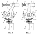
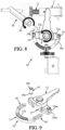
- the 10' control device of the Figures 6-9 corresponds to a variant of the example of Figures 1-5 still according to the first embodiment of the invention, which differs from this example only in that the raised terminal portions 18' of the single-piece notched sector 16' respectively have two oblong holes 18a in arcs of a circle symmetrical to each other adapted to receive in curvilinear sliding the fixing elements 19 (visible in the figure) figure 9 and constituted as in Figures 1-6 of two tubular pins 19 provided in this example with collars 19a and locking rings 19b).
- the fixed axis P can be operated directly in the direction of the arrow M by means of an emergency key 20 when the motor 13 is blocked, for example, in order to rotate the arm 12 in the direction allowing the bolt 5 to be moved from its extended position to its retracted position of the figure 8 .
- the bolt 5 can be unlocked without rotating the motor 13 or the pinion 15.
- the notched covering 118 is able to slide in a curvilinear manner in the central portion 116a of the support 117 via a rib 118b in an arc of a circle formed on a lower face of the covering 118 cooperating in sliding with a corresponding groove 117b of the upper face of the central portion 116a.
- This mutual abutment on one side of the notched sector 116, of the covering 118 and of the support 117, allows rotation of the arm 12 by the motor 13 then a return to the initial position by means of the thrust F generated by the spring 11 of the bolt 5 and also, without rotation of the motor 13 or of the pinion 15 (i.e. in particular when the motor 13 is blocked), to directly maneuver the fixed axis P in the direction of the arrow M by means of an emergency key 20 to rotate the arm 12 in the direction allowing the bolt 5 to be brought from its extended position to its retracted position of the figure 12 .
- the control device 110' according to the variant of the second mode of the invention visible in Figures 14-18 is essentially distinguished from the example of Figures 10-13a , in that (see Figures 16-17 ) the notched sector 116' in two parts 117 and 118 further comprises two pre-stressed helical compression springs 119 and 120 respectively mounted on both sides and bearing against the notched covering 118.
- This assembly not only allows rotational drive of the arm 12 but also allows an over-torque on the notching 118a of the covering 118, with a momentary curvilinear sliding of the covering 118 on the support 117 secured to the arm 12, then a return to the initial position when the over-torque is cancelled.
- FIG 16 illustrates the usefulness of the two parts 117 and 118 and of the springs 119 and 120 if the motor 13 is blocked. Indeed, when the bolt 5 is unlocked with the emergency key 20 rotating the fixed axis P in the required direction, the covering 118 slides on the support 117 by compressing one spring 119 and relaxing the other spring 120.
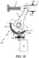
- FIG 18 further illustrates the usefulness of the two parts 117 and 118 and of the springs 119 and 120 if the translation of the bolt 5 is temporarily or permanently blocked in the locked or semi-locked position by an external action (see force F1 exerted on the bolt 5), one of the springs 120 compressing while the other spring 119 relaxes proportionally.
- the control device 110" according to the other variant of the second mode of the invention visible in Figures 19-22a is essentially distinguished from the variant of Figures 14-18 , in that (see Figures 22-22a ) the notched sector 116" in two parts 117 and 118 further comprises separable connecting means of the clip type 121 and drive pins 122 between the notched covering 118 and the sector support 117. As visible in the figure 22a , the clips 121 are arranged on either side of the rib 118b on the lower face of the notched covering 118.
- FIG 21 illustrates the usefulness of the two parts 117 and 118 and the clips/nipples 121 if the motor 13 is blocked. Indeed, when the bolt 5 is unlocked with the emergency key 20, the covering 118 slides relative to the sector support 117 by unclipping (i.e. by separation of the clips 121 and nipples 122).
- the notched covering 118 is held in curvilinear sliding on the sector support 117 secured to the arm 12 by means of the clips 121 and pins 122, then allowing the arm 12 to be disengaged relative to the notched covering 118, for example during an over-torque.
Landscapes
- Engineering & Computer Science (AREA)
- Automation & Control Theory (AREA)
- Lock And Its Accessories (AREA)
Description
La présente invention concerne une serrure d'une porte palière d'un appareil élévateur avec pêne de verrouillage/ déverrouillage de cette porte, une telle serrure pouvant équiper un ascenseur ou tout autre appareil élévateur notamment pour des personnes à mobilité réduite.The present invention relates to a lock for a landing door of a lifting device with a bolt for locking/unlocking this door, such a lock being able to equip an elevator or any other lifting device in particular for people with reduced mobility.
Pour mémoire, il est rappelé que dans une installation d'appareil élévateur, telle qu'illustrée par le document
Or, il n'est pas toujours possible de disposer d'une telle came d'actionnement du pêne, par exemple dans le cas d'appareils élévateurs ne disposant pas de cabine et destinés au déplacement de personnes à mobilité réduite évoluant par exemple en fauteuil roulant, et dans le cas d'appareils élévateurs à cabines dont toutes les portes palières ne s'ouvrent pas dans un seul sens pour des raisons techniques.However, it is not always possible to have such a cam for actuating the bolt, for example in the case of lifting devices which do not have a cabin and are intended for the movement of persons with reduced mobility, for example in wheelchairs, and in the case of lifting devices with cabins where not all the landing doors open in one direction only for technical reasons.
On comprend que dans ce dernier cas, la came dont est équipée la cabine ne peut pas assurer sa fonction.It is understood that in this latter case, the cam with which the cabin is equipped cannot perform its function.
Pour remédier à cet inconvénient, il est connu de recourir à des dispositifs à commande électrique aptes à agir directement sur le pêne de verrouillage. L'un de ces dispositifs consiste à disposer d'un électroaimant dont le noyau ferromagnétique mobile est couplé à l'organe à commander pouvant être un pêne selon l'exemple d'application choisi. L'électroaimant peut être commandé par un signal électrique en fonction de la position d'une cabine ou d'une plateforme de l'appareil élévateur.To overcome this drawback, it is known to use electrically controlled devices capable of acting directly on the locking bolt. One of these devices consists of having an electromagnet whose movable ferromagnetic core is coupled to the member to be controlled which may be a bolt according to the chosen application example. The electromagnet can be controlled by an electrical signal depending on the position of a cabin or platform of the lifting device.
Un inconvénient majeur de ce dispositif de commande à électroaimant couplé à un pêne usuellement équipé d'un moyen de rappel mécanique, réside dans la force d'attraction d'intensité élevée requise pour agir sur le pêne qui impose d'utiliser pour l'électroaimant une bobine de grandes dimensions. Un autre inconvénient de ce dispositif à électroaimant réside dans le fait que pendant tout le temps d'immobilisation de la cabine à un étage (par exemple la nuit), la bobine est alimentée en permanence afin de maintenir le pêne en position d'ouverture de la porte palière, ce qui est susceptible de provoquer un échauffement pouvant conduire à une destruction rapide de la bobine.A major drawback of this electromagnet control device coupled to a bolt usually equipped with a mechanical return means, lies in the high intensity attraction force required to act on the bolt which requires the use of a large coil for the electromagnet. Another drawback of this electromagnet device lies in the fact that during the entire time the car is immobilized on a floor (for example at night), the coil is permanently powered in order to keep the bolt in the opening position of the landing door, which is likely to cause heating which can lead to rapid destruction of the coil.
Le document de brevet
Un inconvénient majeur de ce dispositif de commande à crémaillère rectiligne montée d'un côté de la tige entraînant le pêne réside dans l'exercice d'une action linéaire et tangentielle sur l'élément de manoeuvre du pêne, effort tangentiel qui génère, d'une part, un couple de rotation variable sur l'élément de manoeuvre en raison de la variation du rayon d'application utilisé et, d'autre part, qui se situe latéralement à l'élément de manoeuvre, ce qui impose d'avoir des positionnement différents du dispositif de commande pour une serrure dont le pêne sort du côté gauche et une serrure dont le pêne sort du côté droit.A major drawback of this control device with a rectilinear rack mounted on one side of the rod driving the bolt lies in the exercise of a linear and tangential action on the operating element of the bolt, a tangential force which generates, on the one hand, a variable rotation torque on the operating element due to the variation of the application radius used and, on the other hand, which is located laterally to the operating element, which requires having different positions of the control device for a lock whose bolt comes out on the left side and a lock whose bolt comes out on the right side.
Un but de la présente invention est de proposer une serrure de porte palière d'un appareil élévateur remédiant notamment aux inconvénients précités.An aim of the present invention is to propose a landing door lock for a lifting device which in particular overcomes the aforementioned drawbacks.
A cet effet, il est proposé une serrure selon la revendication 1.For this purpose, a lock according to claim 1 is provided.
Du fait de l'axe fixe de pivotement, on notera que le couple appliqué au bras de manoeuvre est constant puisque le rayon d'application de l'effort ne change pas, contrairement au dispositif de commande selon le document
On notera également que l'effort de rotation généré par l'actionneur en rotation, tel qu'un moteur électrique, et transmis par ce train d'engrenages, est conçu de telle sorte que l'unité d'actionnement peut être avantageusement utilisable dans le boîtier de la serrure tant pour une serrure dont le pêne sort du côté gauche du boîtier que pour une serrure dont le pêne sort du côté droit du boîtier, i.e. sans requérir de modifications substantielles du dispositif de commande ni des composants additionnels en fonction du côté d'ouverture de la porte. Il en résulte une économie de constituants pour la serrure, quel que soit le côté de verrouillage/ déverrouillage de la porte qui en est équipée.It will also be noted that the rotational force generated by the rotating actuator, such as an electric motor, and transmitted by this gear train, is designed such that the actuating unit can be advantageously used in the lock housing both for a lock whose bolt extends from the left side of the housing and for a lock whose bolt extends from the right side of the housing, i.e. without requiring substantial modifications to the control device or additional components depending on the opening side of the door. This results in a saving of components for the lock, regardless of the locking/unlocking side of the door equipped with it.
Selon une autre caractéristique de l'invention, ledit secteur cranté peut présenter une forme de demi-couronne circulaire comprenant une portion centrale recouverte de crans radiaux et deux portions terminales qui sont respectivement fixées à deux ailes prolongeant à angle droit un sommet dudit bras de manoeuvre monté sur ledit axe fixe de pivotement, ledit bras de manoeuvre pouvant présenter globalement une forme de T dont l'extrémité libre opposée audit sommet est reliée audit organe, de telle sorte que lesdites portions terminales dudit secteur cranté forment un triangle sensiblement isocèle avec ladite extrémité libre dudit bras de manoeuvre.According to another characteristic of the invention, said notched sector may have the shape of a circular half-crown comprising a central portion covered with radial notches and two terminal portions which are respectively fixed to two wings extending at right angles a vertex of said operating arm mounted on said fixed pivot axis, said operating arm may have a general T shape whose free end opposite said vertex is connected to said member, such that said terminal portions of said notched sector form a substantially isosceles triangle with said free end of said operating arm.
On notera que cette forme de demi-cercle pour la crémaillère courbe dont les dents formant ces crans radiaux (i.e. des dents dont les sommets ou arêtes sommitales s'étendent le long de la direction d'un rayon du demi-cercle passant par l'axe fixe de pivotement) sont prévues au centre de cette crémaillère permet ainsi, via ses portions terminales, le montage solidaire en rotation du bras de manoeuvre et de cette crémaillère de telle sorte que la crémaillère courbe et le bras dont elle est pourvue admettent comme plan commun de symétrie le plan longitudinal médian du bras.It will be noted that this semi-circle shape for the curved rack whose teeth forming these radial notches (i.e. teeth whose summits or summit edges extend along the direction of a radius of the semi-circle passing through the fixed pivot axis) are provided at the center of this rack thus allows, via its terminal portions, the assembly integral in rotation with the operating arm and this rack such that the curved rack and the arm with which it is provided admit as a common plane of symmetry the median longitudinal plane of the arm.
Selon un premier mode de réalisation de l'invention, ledit secteur cranté est monobloc, ladite portion centrale recouverte de crans radiaux étant formée d'un seul tenant avec lesdites portions terminales qui sont respectivement fixées auxdites ailes dudit bras de manoeuvre par deux éléments de fixation d'axes parallèles audit axe fixe de pivotement.According to a first embodiment of the invention, said notched sector is in one piece, said central portion covered with radial notches being formed in one piece with said terminal portions which are respectively fixed to said wings of said operating arm by two fixing elements with axes parallel to said fixed pivot axis.
Ces éléments de fixation sont par exemple montés de manière à relier le bras de manoeuvre au secteur cranté de manière indéformable (i.e. sans degré de liberté du bras par rapport au secteur cranté).These fixing elements are, for example, mounted in such a way as to connect the operating arm to the notched sector in a non-deformable manner (i.e. without any degree of freedom of the arm relative to the notched sector).
Selon une variante de réalisation de l'invention conformément à ce premier mode, lesdites portions terminales sont pourvues de trous oblongs en arcs de cercle, pour permettre un déplacement desdits éléments de fixation dans lesdits trous oblongs lorsque, sans utiliser ledit actionneur ni ledit au moins un pignon, on imprime une rotation audit axe fixe de pivotement par une clef extérieure de secours entraînant la rotation dudit bras de manoeuvre et la translation dudit organe, pour l'obtention réversible de ladite position rentrée de déverrouillage.According to an alternative embodiment of the invention in accordance with this first mode, said terminal portions are provided with oblong holes in arcs of a circle, to allow movement of said fixing elements in said oblong holes when, without using said actuator or said at least one pinion, rotation is imparted to said fixed pivot axis by an external emergency key causing rotation of said operating arm and translation of said member, for reversibly obtaining said retracted unlocking position.
On notera que ces trous oblongs permettent ainsi le déblocage de l'organe par le bras de manoeuvre au moyen de cette clef lorsque l'actionneur, tel qu'un moteur électrique, est bloqué.It should be noted that these oblong holes thus allow the unlocking of the organ by the operating arm using this key when the actuator, such as an electric motor, is blocked.
Selon un second mode de réalisation de l'invention, ledit secteur cranté est réalisé en au moins deux parties, comprenant :
- un support de secteur qui forme à la fois ladite portion centrale et lesdites portions terminales et est fixé audit bras de manoeuvre, et
- un revêtement cranté amovible présentant lesdits crans radiaux qui est monté coulissant dans ladite portion centrale dudit support de sorte à se trouver en butée en une extrémité de ladite portion centrale.
- a sector support which forms both said central portion and said end portions and is fixed to said operating arm, and
- a removable notched covering having said radial notches which is slidably mounted in said central portion of said support so as to be in abutment at one end of said central portion.
Ce montage coulissant du revêtement cranté dans la portion centrale du support peut être obtenu par un assemblage de type nervure en arc de cercle formant coulisseau sur la face inférieure du revêtement (opposée à sa face supérieure présentant les crans) / rainure en arc de cercle formée sur la face supérieure en regard de la portion centrale du support, ou inversement.This sliding assembly of the notched covering in the central portion of the support can be obtained by an assembly of the arc-shaped rib type forming a slide on the lower face of the covering. (opposite its upper face showing the notches) / groove in an arc of a circle formed on the upper face opposite the central portion of the support, or vice versa.
On notera que ce montage coulissant avec butée latérale permet, en plus du déverrouillage précité par la clef de secours, une mise en rotation du bras de manoeuvre grâce à la rotation générée par l'actionneur et transmise à et par la crémaillère courbe, puis un retour en position initiale par l'intermédiaire de la poussée exercée par les moyens de rappel appliqués contre l'organe de verrouillage/ déverrouillage. La butée entre le revêtement cranté et le support de secteur sert pour l'entraînement par le moteur, alors que l'éloignement de cette butée sert lors du déverrouillage par la clef.It should be noted that this sliding assembly with lateral stop allows, in addition to the aforementioned unlocking by the emergency key, a rotation of the operating arm thanks to the rotation generated by the actuator and transmitted to and by the curved rack, then a return to the initial position by means of the thrust exerted by the return means applied against the locking/unlocking member. The stop between the notched coating and the sector support is used for driving by the motor, while the distance from this stop is used during unlocking by the key.
Selon une variante de réalisation de l'invention conformément à ce second mode, ledit secteur cranté comprend en outre des moyens de rappel comprenant deux ressorts hélicoïdaux de compression précontraints, qui sont respectivement montés des deux côtés et en appui contre ledit revêtement cranté, de sorte à autoriser un sur-couple exercé sur ledit revêtement cranté entraînant par coulissement relatif un déplacement momentané en arc de cercle dudit revêtement cranté par rapport audit support de secteur puis un retour en position initiale quand ledit sur-couple est annulé, l'un desdits ressorts précontraints étant comprimé et l'autre détendu lors de l'obtention de ladite position de déverrouillage.According to an alternative embodiment of the invention in accordance with this second mode, said notched sector further comprises return means comprising two pre-stressed helical compression springs, which are respectively mounted on both sides and bearing against said notched covering, so as to allow an over-torque exerted on said notched covering causing, by relative sliding, a momentary displacement in an arc of a circle of said notched covering relative to said sector support then a return to the initial position when said over-torque is cancelled, one of said pre-stressed springs being compressed and the other relaxed when said unlocking position is obtained.
On notera que cette variante permet ainsi non seulement d'obtenir ce sur-couple avec un déplacement curviligne réversible du revêtement cranté sur le support de secteur, mais encore un entraînement en rotation du bras de manoeuvre même lorsque l'actionneur, tel qu'un moteur électrique, est bloqué, étant précisé que ce coulissement curviligne comprime l'un des deux ressorts précontraints en détendant l'autre.It should be noted that this variant thus makes it possible not only to obtain this over-torque with a reversible curvilinear movement of the notched coating on the sector support, but also a rotational drive of the operating arm even when the actuator, such as an electric motor, is blocked, it being specified that this curvilinear sliding compresses one of the two pre-stressed springs while relaxing the other.
Selon une autre variante de réalisation de l'invention conformément à ce second mode, ledit secteur cranté comprend en outre des moyens de liaison séparables de type à clips et tétons d'entraînement entre ledit revêtement cranté et ledit support de secteur, lesdits moyens de liaison étant adaptés pour maintenir ledit revêtement cranté en déplacement suivant un arc de cercle par rapport audit support de secteur par coulissement relatif et pour l'obtention d'un débrayage dudit bras de manoeuvre par rapport audit secteur cranté notamment lors d'un sur-couple exercé sur ledit revêtement cranté, ou pour obtenir la rotation dudit bras de manoeuvre et la translation dudit organe dans ladite position de déverrouillage, par une rotation imprimée directement audit axe fixe de pivotement par ladite clef de secours.According to another variant embodiment of the invention in accordance with this second mode, said notched sector further comprises separable connecting means of the clip and drive pin type between said notched covering and said sector support, said connecting means being adapted to maintain said notched covering in movement according to an arc of a circle relative to said sector support by relative sliding and for obtaining a disengagement of said operating arm relative to said notched sector, in particular during an over-torque exerted on said notched coating, or for obtaining the rotation of said operating arm and the translation of said member in said unlocking position, by a rotation directly imparted to said fixed pivot axis by said emergency key.
On notera ainsi que ces moyens de liaison à clips et tétons permettent d'utiliser la clef de secours pour faire coulisser de manière curviligne avec « déclipsage » (i.e. séparation des clips) le revêtement cranté sur le support de secteur, lorsque l'actionneur, tel qu'un moteur électrique, est bloqué.It will thus be noted that these clip and stud connection means make it possible to use the emergency key to slide in a curvilinear manner with “unclipping” (i.e. separation of the clips) the notched covering on the sector support, when the actuator, such as an electric motor, is blocked.
Selon une autre caractéristique de l'invention, dans ladite position rentrée de déverrouillage, ledit axe fixe de pivotement peut être situé sensiblement à égale distance d'une extrémité desdits moyens de rappel montés contre ladite première paroi dudit boîtier et d'une extrémité axialement externe opposée dudit organe montée affleurant ladite seconde paroi dudit boîtier.According to another characteristic of the invention, in said retracted unlocking position, said fixed pivot axis can be located substantially at an equal distance from one end of said return means mounted against said first wall of said housing and from an axially external end opposite said member mounted flush with said second wall of said housing.
On notera que ledit axe fixe de pivotement est en outre perpendiculaire à un plan contenant ledit axe de translation et l'axe longitudinal de symétrie du bras de manoeuvre.It will be noted that said fixed pivot axis is further perpendicular to a plane containing said translation axis and the longitudinal axis of symmetry of the operating arm.
Selon une autre caractéristique particulièrement avantageuse de l'invention commune aux premier et second modes de réalisation précités, ledit actionneur en rotation comprend un moteur électrique pas à pas couplé à une électronique de commande et optionnellement en outre à un groupe réducteur.According to another particularly advantageous characteristic of the invention common to the first and second embodiments mentioned above, said rotation actuator comprises a stepper electric motor coupled to control electronics and optionally also to a reduction group.
On notera en effet que l'utilisation d'un moteur électrique pas à pas spécifiquement en combinaison avec le secteur cranté selon l'invention permet l'obtention d'un couple final plus élevé sur le bras de manoeuvre pour une consommation électrique plus réduite, qu'avec un moteur électrique usuel.It will be noted that the use of a stepper electric motor specifically in combination with the notched sector according to the invention makes it possible to obtain a higher final torque on the operating arm for a lower electrical consumption than with a conventional electric motor.
De manière générale, en fonctionnement, l'actionneur tel qu'un moteur électrique de préférence pas à pas est activable à partir d'un signal agissant positivement ou négativement sur son alimentation de manière à modifier la position de l'organe de verrouillage/ déverrouillage, étant rappelé que la clef de secours précitée et la force de rappel indépendante exercée par les moyens de rappels appliqués contre cet organe lors d'une coupure d'alimentation de l'actionneur permettent également de modifier la position de cet organe.Generally speaking, in operation, the actuator such as an electric motor, preferably a stepper motor, can be activated from a signal acting positively or negatively on its power supply so as to modify the position of the locking/unlocking member, it being recalled that the aforementioned emergency key and the independent return force exerted by the return means applied against this member during a power cut to the actuator also make it possible to modify the position of this member.
D'autres caractéristiques, avantages et détails de la présente invention ressortiront à la lecture de la description suivante d'exemples de réalisation de l'invention, donnés à titre illustratif et non limitatif, la description étant réalisée en référence aux dessins joints, parmi lesquels :
- les
figures 1 et 2 sont des vues frontales de l'intérieur d'une serrure pour porte palière d'appareil élévateur selon un exemple du premier mode de l'invention, le pêne de sécurité y étant montré respectivement en position sortie de verrouillage et rentrée de déverrouillage dans le boîtier recevant le dispositif de commande du pêne, - les
figures 3 et 4 sont des vues frontales de ce seul dispositif de commande isolé (montré dans le boîtier), respectivement dans les positions sortie et rentrée du pêne selon lesfigures 1 et 2 , - la
figure 5 est une vue de dessus et en perspective du bras de manoeuvre monté solidaire d'un secteur cranté monobloc du dispositif selon lesfigures 1 à 4 , - les
figures 6 et 7 sont des vues frontales du seul dispositif de commande selon une variante du premier mode illustré auxfigures 1 à 4 avec des trous oblongs dans le secteur cranté, respectivement dans les positions sortie et rentrée du pêne, - la
figure 8 est une vue frontale du dispositif de commande desfigures 6 et 7 montrant l'utilisation d'une clé de secours pour déverrouiller le pêne, - la
figure 9 est une vue éclatée de dessus et en perspective montrant la fixation du bras de manoeuvre par les trous oblongs du secteur cranté desfigures 6 à 8 , - les
figures 10 et 11 sont des vues frontales du seul dispositif de commande respectivement en position sortie et rentrée du pêne, selon un exemple du second mode de réalisation de l'invention avec le secteur cranté en deux parties, - la
figure 12 est une vue frontale du dispositif de commande desfigures 10 et 11 montrant l'utilisation d'une clé de secours pour déverrouiller le pêne, - la
figure 13 est une vue éclatée de dessus et en perspective montrant le montage en coulissement d'un revêtement cranté, visible dans la vue de dessous en perspective de lafigure 13a , dans un support du secteur cranté, - les
figures 14 et 15 sont des vues frontales du seul dispositif de commande respectivement en position sortie et rentrée du pêne, selon une variante du second mode de réalisation de l'invention du secteur cranté en deux parties, qui est couplé à deux ressorts précontraints, - la
figure 16 est une vue frontale du dispositif de commande desfigures 14 et 15 montrant l'utilisation d'une clé de secours pour déverrouiller le pêne, - la
figure 17 est une vue éclatée de dessus et en perspective montrant le montage d'un revêtement cranté, visible dans la vue de dessous en perspective de lafigure 17a , dans un support du secteur cranté muni des deux ressorts desfigures 14 à 16 , - la
figure 18 est une vue frontale avec arrachements partiels du dispositif de commande desfigures 14 à 17 , montrant les positions des deux ressorts si la translation du pêne est bloquée en position verrouillée ou semi-verrouillée par une action extérieure, - les
figures 19 et 20 sont des vues frontales du seul dispositif de commande respectivement en position sortie et rentrée du pêne, selon une autre variante du second mode de réalisation de l'invention du secteur cranté en deux parties avec clips et tétons d'entrainement, - la
figure 21 est une vue frontale du dispositif de commande desfigures 19 et 20 montrant l'utilisation d'une clé de secours pour déverrouiller le pêne par séparation des clips et des tétons, et - la
figure 22 est une vue éclatée de dessus et en perspective montrant le montage d'un revêtement cranté, visible dans la vue de dessous en perspective de lafigure 22a , dans un support du secteur cranté muni des clips et tétons desfigures 19 à 21 .
- THE
Figures 1 and 2 are front views of the interior of a lock for a landing door of a lifting device according to an example of the first embodiment of the invention, the safety bolt being shown respectively in the extended locking position and the retracted unlocking position in the housing receiving the bolt control device, - THE
Figures 3 and 4 are front views of this single isolated control device (shown in the housing), respectively in the extended and retracted positions of the bolt according to theFigures 1 and 2 , - there
figure 5 is a top and perspective view of the operating arm mounted integrally with a single-piece notched sector of the device according to theFigures 1 to 4 , - THE
Figures 6 and 7 are front views of the single control device according to a variant of the first mode illustrated inFigures 1 to 4 with oblong holes in the notched sector, respectively in the extended and retracted positions of the bolt, - there
figure 8 is a front view of the control device of theFigures 6 and 7 showing the use of a spare key to unlock the bolt, - there
figure 9 is an exploded top and perspective view showing the fixing of the operating arm by the oblong holes of the notched sector of thefigures 6 to 8 , - THE
Figures 10 and 11 are front views of the single control device respectively in the extended and retracted position of the bolt, according to an example of the second embodiment of the invention with the notched sector in two parts, - there
figure 12 is a front view of the control device of theFigures 10 and 11 showing the use of a spare key to unlock the bolt, - there
figure 13 is an exploded top and perspective view showing the sliding assembly of a notched covering, visible in the bottom perspective view of thefigure 13a , in a notched sector support, - THE
Figures 14 and 15 are front views of the single control device respectively in the extended and retracted position of the bolt, according to a variant of the second embodiment of the invention of the notched sector in two parts, which is coupled to two pre-stressed springs, - there
figure 16 is a front view of the control device of theFigures 14 and 15 showing the use of a spare key to unlock the bolt, - there
figure 17 is an exploded top and perspective view showing the assembly of a notched covering, visible in the bottom perspective view of thefigure 17a , in a notched sector support fitted with the two springs of theFigures 14 to 16 , - there
figure 18 is a front view with partial cutaways of the control device of theFigures 14 to 17 , showing the positions of the two springs if the translation of the bolt is blocked in the locked or semi-locked position by an external action, - THE
Figures 19 and 20 are front views of the single control device respectively in the extended and retracted positions of the bolt, according to another variant of the second embodiment of the invention of the notched sector in two parts with clips and drive pins, - there
figure 21 is a front view of the control device of theFigures 19 and 20 showing the use of a spare key to unlock the bolt by separating the clips and pins, and - there
figure 22 is an exploded top and perspective view showing the assembly of a notched covering, visible in the bottom perspective view of thefigure 22a , in a notched sector support fitted with the clips and nipples of theFigures 19 to 21 .
La serrure 1 de porte palière pour appareil élévateur selon l'exemple du premier mode de l'invention visible aux
un boîtier 2 de la serrure 1 notamment délimité par une première paroi latérale 3, une seconde paroi latérale 4 opposée traversée par un pêne de sécurité 5, une paroi supérieure 6 et une paroi inférieure 7 (la paroi frontale opposée à la paroi de fond 8 n'étant pas visible auxfigures 1-2 ),le pêne 5 pour verrouiller/ déverrouiller la porte palière en position fermée, et- un dispositif de commande 10 apte à
commander le pêne 5 en position sortie de verrouillage et rentrée de déverrouillage.
- a
housing 2 of the lock 1 in particular delimited by afirst side wall 3, a secondopposite side wall 4 crossed by asafety bolt 5, anupper wall 6 and a lower wall 7 (the front wall opposite thebottom wall 8 not being visible to theFigures 1-2 ), -
bolt 5 to lock/unlock the landing door in the closed position, and - a
control device 10 capable of controlling thebolt 5 in the extended locking position and retracted unlocking position.
Le dispositif de commande 10 comprend essentiellement (voir
- des moyens de
manoeuvre 10a du pêne 5 adaptés pour l'amener réversiblement en translation suivant un axe de translation X (perpendiculaire aux plans des première et seconde parois latérales 3 et 4) de la position sortie de lafigure 1 à la position rentrée de lafigure 2 par rapport à la seconde paroi latérale 4, et - une unité d'actionnement 10b activable par un signal électrique et adaptée pour actionner les moyens de
manoeuvre 10a.
- operating means 10a of the
bolt 5 adapted to bring it reversibly into translation along a translation axis X (perpendicular to the planes of the first andsecond side walls 3 and 4) from the extended position of thefigure 1 in the retracted position of thefigure 2 relative to thesecond side wall 4, and - an
actuating unit 10b activatable by an electrical signal and adapted to actuate the operating means 10a.
Plus précisément, les moyens de manoeuvre 10a comprennent :
- des moyens de rappel 11 constitués dans cet exemple d'un ressort hélicoïdal de compression qui rappelle le pêne 5 en position sortie avec une force de rappel d'intensité F et est monté en appui suivant l'axe de translation X entre la première paroi 3 et une extrémité axialement interne 5a du pêne 5, et
- un bras de
manoeuvre 12 relié (e.g. articulé ou couplé d'une autre manière)au pêne 5 de telle sorte qu'une rotation dubras 12 entraîne une translation du pêne 5 à travers la seconde paroi 4.
- return means 11 consisting in this example of a helical compression spring which returns the
bolt 5 to the extended position with a return force of intensity F and is mounted in support along the translation axis X between thefirst wall 3 and an axiallyinternal end 5a of thebolt 5, and - an
operating arm 12 connected (eg articulated or otherwise coupled) to thebolt 5 such that a rotation of thearm 12 causes a translation of thebolt 5 through thesecond wall 4.
Selon l'invention, l'unité d'actionnement 10b comprend (voir
- * un actionneur en
rotation 13 constitué de préférence d'un moteur électrique pas à pas couplé à une électronique de commande (non représentée) et optionnellement à un groupe réducteur, et - * des moyens de
transmission 14 de la rotation du moteur électrique 13 au bras demanoeuvre 12 qui comprennent un train d'engrenages comprenantun pignon 15 d'axe Y (perpendiculaire aux plans des parois supérieure 6et inférieure 7 du boîtier 2), couplé à un arbre de sortie 13a du moteur 13, et un secteur cranté 16 formant crémaillère courbe avec lequel s'engrène le pignon 15, le secteur cranté 16 étant monté pivotant autour d'un axe de pivotement P fixe par rapport à la paroi de fond 8 du boîtier 2 (l'axe fixe P est perpendiculaire aux plans des deux parois de fond 8 et frontale du boîtier 2) et sur lequel axe fixe P est monté pivotant lebras 12, lui-même monté solidaire en rotation du secteur cranté 16.
- * a rotating
actuator 13 preferably consisting of a stepper electric motor coupled to control electronics (not shown) and optionally to a reduction group, and - * means 14 for transmitting the rotation of the
electric motor 13 to theoperating arm 12 which comprise a gear train comprising apinion 15 with an axis Y (perpendicular to the planes of the upper 6 and lower 7 walls of the housing 2), coupled to anoutput shaft 13a of themotor 13, and a notchedsector 16 forming a curved rack with which thepinion 15 meshes, the notchedsector 16 being pivotally mounted about a pivot axis P fixed relative to thebottom wall 8 of the housing 2 (the fixed axis P is perpendicular to the planes of the two bottom 8 and front walls of the housing 2) and on which fixed axis P is pivotally mounted thearm 12, itself mounted integral in rotation with the notchedsector 16.
Comme visible aux
On voit aux
Comme visible à la
En fonctionnement, un engrènement via le moteur électrique 13 du pignon 15 sur le secteur cranté 16 entraîne une rotation de ce dernier autour de l'axe fixe P et un pivotement du bras 12 sur cet axe fixe P pour la commande en translation réversible du pêne 5 de sa position sortie de la
On voit en outre aux
Dans la description suivante de variantes et d'un autre mode de réalisation de l'invention, les mêmes références numériques désignent des éléments de même structure ou au moins de même fonction, étant précisé que le principe de fonctionnement de chaque nouveau dispositif de commande présenté est similaire à celui qui vient d'être décrit en référence aux
Le dispositif de commande 10' des
Comme visible à la
Le dispositif de commande 110 selon l'exemple du second mode de l'invention visible aux
- un support de secteur 117 qui forme à la fois une portion centrale 116a et des portions terminales 116b du secteur 116 et qui est fixé au
bras 12, et - un revêtement cranté 118 amovible présentant les crans radiaux 118a sur sa face supérieure, qui est monté coulissant dans la portion centrale 116a du
support 117 de sorte à se trouver en butée en une extrémité de laportion centrale 116a.
- a
sector support 117 which forms both acentral portion 116a and endportions 116b of thesector 116 and which is fixed to thearm 12, and - a removable notched covering 118 having the
radial notches 118a on its upper face, which is slidably mounted in thecentral portion 116a of thesupport 117 so as to be in abutment at one end of thecentral portion 116a.
On voit aux
Cette mise en butée mutuelle, d'un côté du secteur cranté 116, du revêtement 118 et du support 117, permet une mise en rotation du bras 12 par le moteur 13 puis un retour en position initiale par l'intermédiaire de la poussée F générée par le ressort 11 du pêne 5 et également, sans rotation du moteur 13 ni du pignon 15 (i.e. notamment quand le moteur 13 est bloqué), de manoeuvrer directement l'axe fixe P dans le sens de la flèche M au moyen d'une clef de secours 20 pour faire tourner le bras 12 dans le sens permettant d'amener le pêne 5 de sa position sortie à sa position rentrée de la
Le dispositif de commande 110' selon la variante du second mode de l'invention visible aux
La
La
Le dispositif de commande 110" selon l'autre variante du second mode de l'invention visible aux
La
De plus, grâce à ce montage, le revêtement cranté 118 est maintenu en coulissement curviligne sur le support de secteur 117 solidaire du bras 12 par l'intermédiaire des clips 121 et tétons 122, permettant alors un débrayage du bras 12 par rapport au revêtement cranté 118 par exemple lors d'un sur-couple.Furthermore, thanks to this assembly, the notched covering 118 is held in curvilinear sliding on the
Claims (9)
- Lock (1) for a landing door of a lifting device, the lock
(1) comprisinga housing (2),a bolt (5) for locking/unlocking the landing door, anda control device (10, 10', 110, 110', 110") for controlling the bolt (5) for locking/unlocking,the device comprising:- operating means (10a) for said bolt (5) adapted to bring it reversibly into translation along a translation axis (X) from an extended locking position to a retracted unlocking position relative to the housing (2) of the lock (1), said operating means comprising:* return means (11) which return said bolt (5) to the extended locking position and which are mounted to bear along said translation axis between a first wall (3) of said housing (2) and an axially internal end (5a) of said bolt (5), said return means comprising for example a helical compression spring (11), and* an operating arm (12) connected to said bolt (5) such that a rotation of said operating arm (12) causes a translation of said bolt (5) through a second wall (4) of said housing (2) opposite of said first wall (3), the said operating arm (12) being pivotally mounted about a fixed pivot axis (P) relative to said housing (2) which is orthogonal and non-intersecting to said translation axis (X); and- an actuating unit (10b) activatable by an electrical signal and adapted to actuate in rotation said operating arm (12), the actuating unit comprising:* a rotation actuator (13) comprising for example an electric motor (13), and* transmission means (14) of the rotation of said actuator (13) to said operating arm (12), said transmission means (14) comprising a gear train comprising at least one pinion (15) coupled to an output shaft (13a) of said actuator (13), characterized in that- said transmission means (14) comprise a notched sector (16, 16', 116, 116', 116") forming a curved rack with which said at least one pinion (15) meshes, said notched sector being pivotally mounted about said fixed pivot axis (P),- the operating arm (12) is mounted integral in rotation with said notched sector, such that meshing of said at least one pinion (15) on said notched sector causes rotation of said notched sector about said fixed axis (P) and pivoting of said operating arm (12) on said fixed axis (P) for the translational control of said bolt (5),- said fixed pivot axis (P) is provided parallel to and substantially at an equal distance from said first wall (3) and said second wall (4) of said housing while said translation axis (X) of said bolt (5) is provided perpendicular to said first wall and to said second wall. - Lock (1) according to claim 1, wherein said notched sector (16, 16', 116, 116', 116") has a circular half-crown shape comprising a central portion (17, 116a) covered with radial notches (17a, 118a).
- Lock (1) according to claim 2, wherein said notched sector (16, 16') is in one piece, said central portion (17) covered with radial notches (17a) being formed in one piece with end portions (18, 18') of said notched sector which are respectively fixed to said operating arm (12) by two fixing elements (19) with axes parallel to said fixed pivot axis (P).
- Lock (1) according to claim 3, in which said terminal portions (18') are provided with oblong holes (18a) in arcs of a circle, to allow movement of said fixing elements (19) in said oblong holes when, without using said actuator (13) or said at least one pinion (15), rotation is imparted to said fixed pivot axis (P) by an external emergency key (20) causing rotation of said operating arm (12) and translation of said bolt (5), for reversibly obtaining said retracted unlocking position.
- Lock (1) according to claim 2, in which said notched sector (116, 116', 116") is made in at least two parts, comprising:- a sector support (117) which forms both said central portion (116a) and end portions (116b) of said notched sector and which is fixed to said operating arm (12), and- a removable notched covering (118) having said radial notches (118a) which is slidably mounted in said central portion of said support so as to be in abutment at one end of said central portion.
- Lock (1) according to claim 5, in which said notched sector (116') further comprises return means comprising two pre-stressed helical compression springs (119 and 120), which are respectively mounted on both sides and bearing against said notched covering (118), so as to allow an over-torque exerted on said notched covering causing by relative sliding a momentary displacement in an arc of a circle of said notched covering relative to said sector support (117) then a return to the initial position when said over-torque is cancelled, one of said pre-stressed springs (120) being compressed and the other (119) relaxed when said unlocking position is obtained.
- Lock (1) according to claim 5, in which said notched sector (116") further comprises separable connecting means of the clip (121) and pin (122) type for driving between said notched covering (118) and said sector support (117), said connecting means (121 and 122) being adapted to keep said notched covering moving along an arc of a circle relative to said sector support by relative sliding and to obtain a disengagement of said operating arm (12) relative to said notched sector, in particular during an over-torque exerted on said notched covering, or to obtain the rotation of said operating arm and the translation of said bolt (5) in said unlocking position by said rotation imparted directly to said fixed pivot axis (P) by said emergency key (20).
- Lock (1) according to one of the preceding claims, wherein, in said retracted unlocking position, said fixed pivot axis (P) is located substantially equidistant from one end (11a) of said return means (11) mounted against said first wall (3) of said housing (2) and from an axially external end (5b) opposite said bolt (5) flush with said second wall (4) of said housing.
- Lock (1) according to one of the preceding claims, wherein said rotation actuator (13) comprises a stepper electric motor (13) coupled to control electronics and optionally further to a reduction group.
Applications Claiming Priority (1)
| Application Number | Priority Date | Filing Date | Title |
|---|---|---|---|
| FR1853742A FR3080639B1 (en) | 2018-04-27 | 2018-04-27 | DEVICE FOR CONTROLLING A MEMBER FOR LOCKING/UNLOCKING A LEAF ON A FRAME, SUCH AS A BOLT, AND LOCK INCORPORATING THE SAME |
Publications (2)
| Publication Number | Publication Date |
|---|---|
| EP3569552A1 EP3569552A1 (en) | 2019-11-20 |
| EP3569552B1 true EP3569552B1 (en) | 2024-08-21 |
Family
ID=63036100
Family Applications (1)
| Application Number | Title | Priority Date | Filing Date |
|---|---|---|---|
| EP19170908.8A Active EP3569552B1 (en) | 2018-04-27 | 2019-04-24 | Device for controlling a member for locking/ unlocking a door leaf on a frame, such as a bolt, and lock comprising same |
Country Status (2)
| Country | Link |
|---|---|
| EP (1) | EP3569552B1 (en) |
| FR (1) | FR3080639B1 (en) |
Family Cites Families (5)
| Publication number | Priority date | Publication date | Assignee | Title |
|---|---|---|---|---|
| DE185968C (en) * | 1906-01-25 | 1907-05-16 | ||
| US1050648A (en) * | 1912-04-12 | 1913-01-14 | Losh O Harbaugh | Automatic device for elevators. |
| US1557857A (en) * | 1925-01-03 | 1925-10-20 | Warner Elevator Mfg Company | Safety locking apparatus for elevators |
| DE3836693C2 (en) * | 1988-10-28 | 1996-01-25 | Fliether Karl Gmbh & Co | Espagnolette lock |
| FR3048252B1 (en) * | 2016-02-25 | 2020-03-06 | Assa Abloy Cote Picarde | LOCK ASSEMBLY WITH INDEPENDENT DRIVE LINKS |
-
2018
- 2018-04-27 FR FR1853742A patent/FR3080639B1/en active Active
-
2019
- 2019-04-24 EP EP19170908.8A patent/EP3569552B1/en active Active
Also Published As
| Publication number | Publication date |
|---|---|
| EP3569552A1 (en) | 2019-11-20 |
| FR3080639B1 (en) | 2022-07-29 |
| FR3080639A1 (en) | 2019-11-01 |
Similar Documents
| Publication | Publication Date | Title |
|---|---|---|
| FR3078991A1 (en) | Linear actuator opening control for a motor vehicle. | |
| EP3456579A1 (en) | Guide for vehicle seat and vehicle seat comprising such a guide | |
| FR2503233A1 (en) | POSITION ADJUSTMENT DEVICE, ESPECIALLY COMBINED INSTALLATION OF GLASS MANUFACTURING AND CENTRAL LOCKING OF MOTOR VEHICLE DOOR | |
| FR3023865A1 (en) | HANDLE ASSEMBLY FOR A MOTOR VEHICLE AND OPENING COMPRISING SUCH A HANDLE ASSEMBLY | |
| EP3405633A1 (en) | External opening control of a motor vehicle | |
| FR3032424A1 (en) | DEVICE FOR MANEUVERING AT LEAST ONE AIRCRAFT HAT COMPRISING A CONTROL HANDLE | |
| FR2654767A1 (en) | MOTOR VEHICLE DOOR OPENING MECHANISM AND DOOR COMPRISING SAME. | |
| FR3001488A1 (en) | Locking assembly for locking and unlocking e.g. petrol supply access trap door, articulated at door frame of e.g. lorry, has housing comprising passage formed, so that locking element in unlocking position crosses passage to leave housing | |
| EP2622157B1 (en) | Vehicle door handle comprising two levers | |
| FR2920461A1 (en) | Opening frame e.g. front bonnet, maintaining device for motor vehicle, has connection unit for connecting locking bolt and remotely actuation assembly with respect to each other for allowing transmission of unlocking control to locking bolt | |
| FR2958962A1 (en) | Interior opening controller for controlling opening frame i.e. door, of motor vehicle, has mechanical actuation units and electric actuation units arranged on single case, where switch of electric actuation units is arranged on case | |
| FR2601992A1 (en) | MODULAR GROUP CYLINDRICAL LOCK-BARILLET | |
| WO2020094688A1 (en) | Emergency opening device for an aircraft door, with rotary release | |
| FR2816977A1 (en) | Electrically powered door lock has motor with screw and nut drive to slide actuating bolt | |
| EP3569552A1 (en) | Device for controlling a member for locking/ unlocking a door leaf on a frame, such as a bolt, and lock comprising same | |
| EP0989266B1 (en) | Lock with automatic unlocking on opening | |
| FR2880852A1 (en) | Glove compartment for motor vehicle, has trough moved between retracted and deployed positions by rotating around vertical axle, where trough is moved towards rear and left with respect to retracted position when in deployed position | |
| EP0906997A1 (en) | Locking device comprising a cam operated transmission element | |
| EP0243214B1 (en) | Locking device for use as an anti-theft means for an electric lock of a motor vehicle, and such a lock | |
| EP0837208B1 (en) | Espagnolette brake device and sliding wing comprising such a device | |
| WO2012052533A1 (en) | Control device for a vehicle door locking system | |
| FR2941544A3 (en) | MANUAL ACTUATING DEVICE FOR TWO BODIES OF MOTOR VEHICLE TO BE ACTIONED ALTERNATIVELY | |
| FR2753224A1 (en) | Electromagnetic lock for remotely controlled door release esp. of manually closed fire doors | |
| EP4257781B1 (en) | Handle for a truck door | |
| EP1657380B1 (en) | Actuator device for a wing deadlock mechanism with press-in handle and wing equipped with such a device |
Legal Events
| Date | Code | Title | Description |
|---|---|---|---|
| PUAI | Public reference made under article 153(3) epc to a published international application that has entered the european phase |
Free format text: ORIGINAL CODE: 0009012 |
|
| STAA | Information on the status of an ep patent application or granted ep patent |
Free format text: STATUS: THE APPLICATION HAS BEEN PUBLISHED |
|
| AK | Designated contracting states |
Kind code of ref document: A1 Designated state(s): AL AT BE BG CH CY CZ DE DK EE ES FI FR GB GR HR HU IE IS IT LI LT LU LV MC MK MT NL NO PL PT RO RS SE SI SK SM TR |
|
| AX | Request for extension of the european patent |
Extension state: BA ME |
|
| STAA | Information on the status of an ep patent application or granted ep patent |
Free format text: STATUS: REQUEST FOR EXAMINATION WAS MADE |
|
| 17P | Request for examination filed |
Effective date: 20200520 |
|
| RBV | Designated contracting states (corrected) |
Designated state(s): AL AT BE BG CH CY CZ DE DK EE ES FI FR GB GR HR HU IE IS IT LI LT LU LV MC MK MT NL NO PL PT RO RS SE SI SK SM TR |
|
| STAA | Information on the status of an ep patent application or granted ep patent |
Free format text: STATUS: EXAMINATION IS IN PROGRESS |
|
| 17Q | First examination report despatched |
Effective date: 20210111 |
|
| GRAP | Despatch of communication of intention to grant a patent |
Free format text: ORIGINAL CODE: EPIDOSNIGR1 |
|
| STAA | Information on the status of an ep patent application or granted ep patent |
Free format text: STATUS: GRANT OF PATENT IS INTENDED |
|
| INTG | Intention to grant announced |
Effective date: 20240311 |
|
| GRAS | Grant fee paid |
Free format text: ORIGINAL CODE: EPIDOSNIGR3 |
|
| GRAA | (expected) grant |
Free format text: ORIGINAL CODE: 0009210 |
|
| STAA | Information on the status of an ep patent application or granted ep patent |
Free format text: STATUS: THE PATENT HAS BEEN GRANTED |
|
| AK | Designated contracting states |
Kind code of ref document: B1 Designated state(s): AL AT BE BG CH CY CZ DE DK EE ES FI FR GB GR HR HU IE IS IT LI LT LU LV MC MK MT NL NO PL PT RO RS SE SI SK SM TR |
|
| REG | Reference to a national code |
Ref country code: GB Ref legal event code: FG4D Free format text: NOT ENGLISH |
|
| REG | Reference to a national code |
Ref country code: CH Ref legal event code: EP |
|
| REG | Reference to a national code |
Ref country code: DE Ref legal event code: R096 Ref document number: 602019057272 Country of ref document: DE |
|
| REG | Reference to a national code |
Ref country code: IE Ref legal event code: FG4D Free format text: LANGUAGE OF EP DOCUMENT: FRENCH |
|
| P01 | Opt-out of the competence of the unified patent court (upc) registered |
Free format text: CASE NUMBER: APP_53077/2024 Effective date: 20240923 |
|
| REG | Reference to a national code |
Ref country code: LT Ref legal event code: MG9D |
|
| REG | Reference to a national code |
Ref country code: NL Ref legal event code: MP Effective date: 20240821 |
|
| PG25 | Lapsed in a contracting state [announced via postgrant information from national office to epo] |
Ref country code: NO Free format text: LAPSE BECAUSE OF FAILURE TO SUBMIT A TRANSLATION OF THE DESCRIPTION OR TO PAY THE FEE WITHIN THE PRESCRIBED TIME-LIMIT Effective date: 20241121 |
|
| REG | Reference to a national code |
Ref country code: AT Ref legal event code: MK05 Ref document number: 1715346 Country of ref document: AT Kind code of ref document: T Effective date: 20240821 |
|
| PG25 | Lapsed in a contracting state [announced via postgrant information from national office to epo] |
Ref country code: PT Free format text: LAPSE BECAUSE OF FAILURE TO SUBMIT A TRANSLATION OF THE DESCRIPTION OR TO PAY THE FEE WITHIN THE PRESCRIBED TIME-LIMIT Effective date: 20241223 Ref country code: NL Free format text: LAPSE BECAUSE OF FAILURE TO SUBMIT A TRANSLATION OF THE DESCRIPTION OR TO PAY THE FEE WITHIN THE PRESCRIBED TIME-LIMIT Effective date: 20240821 Ref country code: FI Free format text: LAPSE BECAUSE OF FAILURE TO SUBMIT A TRANSLATION OF THE DESCRIPTION OR TO PAY THE FEE WITHIN THE PRESCRIBED TIME-LIMIT Effective date: 20240821 Ref country code: PL Free format text: LAPSE BECAUSE OF FAILURE TO SUBMIT A TRANSLATION OF THE DESCRIPTION OR TO PAY THE FEE WITHIN THE PRESCRIBED TIME-LIMIT Effective date: 20240821 Ref country code: GR Free format text: LAPSE BECAUSE OF FAILURE TO SUBMIT A TRANSLATION OF THE DESCRIPTION OR TO PAY THE FEE WITHIN THE PRESCRIBED TIME-LIMIT Effective date: 20241122 |
|
| PG25 | Lapsed in a contracting state [announced via postgrant information from national office to epo] |
Ref country code: BG Free format text: LAPSE BECAUSE OF FAILURE TO SUBMIT A TRANSLATION OF THE DESCRIPTION OR TO PAY THE FEE WITHIN THE PRESCRIBED TIME-LIMIT Effective date: 20240821 |
|
| PG25 | Lapsed in a contracting state [announced via postgrant information from national office to epo] |
Ref country code: LV Free format text: LAPSE BECAUSE OF FAILURE TO SUBMIT A TRANSLATION OF THE DESCRIPTION OR TO PAY THE FEE WITHIN THE PRESCRIBED TIME-LIMIT Effective date: 20240821 |
|
| PG25 | Lapsed in a contracting state [announced via postgrant information from national office to epo] |
Ref country code: IS Free format text: LAPSE BECAUSE OF FAILURE TO SUBMIT A TRANSLATION OF THE DESCRIPTION OR TO PAY THE FEE WITHIN THE PRESCRIBED TIME-LIMIT Effective date: 20241221 Ref country code: AT Free format text: LAPSE BECAUSE OF FAILURE TO SUBMIT A TRANSLATION OF THE DESCRIPTION OR TO PAY THE FEE WITHIN THE PRESCRIBED TIME-LIMIT Effective date: 20240821 |
|
| PG25 | Lapsed in a contracting state [announced via postgrant information from national office to epo] |
Ref country code: HR Free format text: LAPSE BECAUSE OF FAILURE TO SUBMIT A TRANSLATION OF THE DESCRIPTION OR TO PAY THE FEE WITHIN THE PRESCRIBED TIME-LIMIT Effective date: 20240821 |
|
| PG25 | Lapsed in a contracting state [announced via postgrant information from national office to epo] |
Ref country code: ES Free format text: LAPSE BECAUSE OF FAILURE TO SUBMIT A TRANSLATION OF THE DESCRIPTION OR TO PAY THE FEE WITHIN THE PRESCRIBED TIME-LIMIT Effective date: 20240821 Ref country code: RS Free format text: LAPSE BECAUSE OF FAILURE TO SUBMIT A TRANSLATION OF THE DESCRIPTION OR TO PAY THE FEE WITHIN THE PRESCRIBED TIME-LIMIT Effective date: 20241121 |
|
| PG25 | Lapsed in a contracting state [announced via postgrant information from national office to epo] |
Ref country code: RS Free format text: LAPSE BECAUSE OF FAILURE TO SUBMIT A TRANSLATION OF THE DESCRIPTION OR TO PAY THE FEE WITHIN THE PRESCRIBED TIME-LIMIT Effective date: 20241121 Ref country code: PT Free format text: LAPSE BECAUSE OF FAILURE TO SUBMIT A TRANSLATION OF THE DESCRIPTION OR TO PAY THE FEE WITHIN THE PRESCRIBED TIME-LIMIT Effective date: 20241223 Ref country code: PL Free format text: LAPSE BECAUSE OF FAILURE TO SUBMIT A TRANSLATION OF THE DESCRIPTION OR TO PAY THE FEE WITHIN THE PRESCRIBED TIME-LIMIT Effective date: 20240821 Ref country code: NO Free format text: LAPSE BECAUSE OF FAILURE TO SUBMIT A TRANSLATION OF THE DESCRIPTION OR TO PAY THE FEE WITHIN THE PRESCRIBED TIME-LIMIT Effective date: 20241121 Ref country code: NL Free format text: LAPSE BECAUSE OF FAILURE TO SUBMIT A TRANSLATION OF THE DESCRIPTION OR TO PAY THE FEE WITHIN THE PRESCRIBED TIME-LIMIT Effective date: 20240821 Ref country code: LV Free format text: LAPSE BECAUSE OF FAILURE TO SUBMIT A TRANSLATION OF THE DESCRIPTION OR TO PAY THE FEE WITHIN THE PRESCRIBED TIME-LIMIT Effective date: 20240821 Ref country code: IS Free format text: LAPSE BECAUSE OF FAILURE TO SUBMIT A TRANSLATION OF THE DESCRIPTION OR TO PAY THE FEE WITHIN THE PRESCRIBED TIME-LIMIT Effective date: 20241221 Ref country code: HR Free format text: LAPSE BECAUSE OF FAILURE TO SUBMIT A TRANSLATION OF THE DESCRIPTION OR TO PAY THE FEE WITHIN THE PRESCRIBED TIME-LIMIT Effective date: 20240821 Ref country code: GR Free format text: LAPSE BECAUSE OF FAILURE TO SUBMIT A TRANSLATION OF THE DESCRIPTION OR TO PAY THE FEE WITHIN THE PRESCRIBED TIME-LIMIT Effective date: 20241122 Ref country code: FI Free format text: LAPSE BECAUSE OF FAILURE TO SUBMIT A TRANSLATION OF THE DESCRIPTION OR TO PAY THE FEE WITHIN THE PRESCRIBED TIME-LIMIT Effective date: 20240821 Ref country code: ES Free format text: LAPSE BECAUSE OF FAILURE TO SUBMIT A TRANSLATION OF THE DESCRIPTION OR TO PAY THE FEE WITHIN THE PRESCRIBED TIME-LIMIT Effective date: 20240821 Ref country code: BG Free format text: LAPSE BECAUSE OF FAILURE TO SUBMIT A TRANSLATION OF THE DESCRIPTION OR TO PAY THE FEE WITHIN THE PRESCRIBED TIME-LIMIT Effective date: 20240821 Ref country code: AT Free format text: LAPSE BECAUSE OF FAILURE TO SUBMIT A TRANSLATION OF THE DESCRIPTION OR TO PAY THE FEE WITHIN THE PRESCRIBED TIME-LIMIT Effective date: 20240821 |
|
| REG | Reference to a national code |
Ref country code: DE Ref legal event code: R082 Ref document number: 602019057272 Country of ref document: DE Representative=s name: PLASSERAUD IP GMBH, DE |
|
| PG25 | Lapsed in a contracting state [announced via postgrant information from national office to epo] |
Ref country code: RO Free format text: LAPSE BECAUSE OF FAILURE TO SUBMIT A TRANSLATION OF THE DESCRIPTION OR TO PAY THE FEE WITHIN THE PRESCRIBED TIME-LIMIT Effective date: 20240821 Ref country code: DK Free format text: LAPSE BECAUSE OF FAILURE TO SUBMIT A TRANSLATION OF THE DESCRIPTION OR TO PAY THE FEE WITHIN THE PRESCRIBED TIME-LIMIT Effective date: 20240821 Ref country code: SM Free format text: LAPSE BECAUSE OF FAILURE TO SUBMIT A TRANSLATION OF THE DESCRIPTION OR TO PAY THE FEE WITHIN THE PRESCRIBED TIME-LIMIT Effective date: 20240821 |
|
| PG25 | Lapsed in a contracting state [announced via postgrant information from national office to epo] |
Ref country code: EE Free format text: LAPSE BECAUSE OF FAILURE TO SUBMIT A TRANSLATION OF THE DESCRIPTION OR TO PAY THE FEE WITHIN THE PRESCRIBED TIME-LIMIT Effective date: 20240821 |
|
| PG25 | Lapsed in a contracting state [announced via postgrant information from national office to epo] |
Ref country code: CZ Free format text: LAPSE BECAUSE OF FAILURE TO SUBMIT A TRANSLATION OF THE DESCRIPTION OR TO PAY THE FEE WITHIN THE PRESCRIBED TIME-LIMIT Effective date: 20240821 |
|
| PG25 | Lapsed in a contracting state [announced via postgrant information from national office to epo] |
Ref country code: IT Free format text: LAPSE BECAUSE OF FAILURE TO SUBMIT A TRANSLATION OF THE DESCRIPTION OR TO PAY THE FEE WITHIN THE PRESCRIBED TIME-LIMIT Effective date: 20240821 Ref country code: SK Free format text: LAPSE BECAUSE OF FAILURE TO SUBMIT A TRANSLATION OF THE DESCRIPTION OR TO PAY THE FEE WITHIN THE PRESCRIBED TIME-LIMIT Effective date: 20240821 |
|
| REG | Reference to a national code |
Ref country code: DE Ref legal event code: R097 Ref document number: 602019057272 Country of ref document: DE |
|
| PLBE | No opposition filed within time limit |
Free format text: ORIGINAL CODE: 0009261 |
|
| STAA | Information on the status of an ep patent application or granted ep patent |
Free format text: STATUS: NO OPPOSITION FILED WITHIN TIME LIMIT |
|
| PGFP | Annual fee paid to national office [announced via postgrant information from national office to epo] |
Ref country code: DE Payment date: 20250411 Year of fee payment: 7 |
|
| 26N | No opposition filed |
Effective date: 20250522 |
|
| PG25 | Lapsed in a contracting state [announced via postgrant information from national office to epo] |
Ref country code: SE Free format text: LAPSE BECAUSE OF FAILURE TO SUBMIT A TRANSLATION OF THE DESCRIPTION OR TO PAY THE FEE WITHIN THE PRESCRIBED TIME-LIMIT Effective date: 20240821 |
|
| REG | Reference to a national code |
Ref country code: CH Ref legal event code: H13 Free format text: ST27 STATUS EVENT CODE: U-0-0-H10-H13 (AS PROVIDED BY THE NATIONAL OFFICE) Effective date: 20251125 |
|
| PG25 | Lapsed in a contracting state [announced via postgrant information from national office to epo] |
Ref country code: LU Free format text: LAPSE BECAUSE OF NON-PAYMENT OF DUE FEES Effective date: 20250424 |
|
| PG25 | Lapsed in a contracting state [announced via postgrant information from national office to epo] |
Ref country code: MC Free format text: LAPSE BECAUSE OF FAILURE TO SUBMIT A TRANSLATION OF THE DESCRIPTION OR TO PAY THE FEE WITHIN THE PRESCRIBED TIME-LIMIT Effective date: 20240821 |
|
| GBPC | Gb: european patent ceased through non-payment of renewal fee |
Effective date: 20250424 |
|
| REG | Reference to a national code |
Ref country code: BE Ref legal event code: MM Effective date: 20250430 |
|
| PG25 | Lapsed in a contracting state [announced via postgrant information from national office to epo] |
Ref country code: GB Free format text: LAPSE BECAUSE OF NON-PAYMENT OF DUE FEES Effective date: 20250424 |
|
| PG25 | Lapsed in a contracting state [announced via postgrant information from national office to epo] |
Ref country code: BE Free format text: LAPSE BECAUSE OF NON-PAYMENT OF DUE FEES Effective date: 20250430 |
|
| PG25 | Lapsed in a contracting state [announced via postgrant information from national office to epo] |
Ref country code: CH Free format text: LAPSE BECAUSE OF NON-PAYMENT OF DUE FEES Effective date: 20250430 |
|
| PG25 | Lapsed in a contracting state [announced via postgrant information from national office to epo] |
Ref country code: IE Free format text: LAPSE BECAUSE OF NON-PAYMENT OF DUE FEES Effective date: 20250424 |
|
| PGFP | Annual fee paid to national office [announced via postgrant information from national office to epo] |
Ref country code: FR Payment date: 20260217 Year of fee payment: 8 |