EP3568652B1 - Vorrichtung und verfahren zum auftauen eines gefrorenen getränks in einer glastrinkflasche - Google Patents
Vorrichtung und verfahren zum auftauen eines gefrorenen getränks in einer glastrinkflasche Download PDFInfo
- Publication number
- EP3568652B1 EP3568652B1 EP18702901.2A EP18702901A EP3568652B1 EP 3568652 B1 EP3568652 B1 EP 3568652B1 EP 18702901 A EP18702901 A EP 18702901A EP 3568652 B1 EP3568652 B1 EP 3568652B1
- Authority
- EP
- European Patent Office
- Prior art keywords
- housing
- bottle
- glass drinking
- drinking bottle
- heating
- Prior art date
- Legal status (The legal status is an assumption and is not a legal conclusion. Google has not performed a legal analysis and makes no representation as to the accuracy of the status listed.)
- Active
Links
Images









Classifications
-
- A—HUMAN NECESSITIES
- A47—FURNITURE; DOMESTIC ARTICLES OR APPLIANCES; COFFEE MILLS; SPICE MILLS; SUCTION CLEANERS IN GENERAL
- A47G—HOUSEHOLD OR TABLE EQUIPMENT
- A47G19/00—Table service
- A47G19/22—Drinking vessels or saucers used for table service
- A47G19/2288—Drinking vessels or saucers used for table service with means for keeping liquid cool or hot
-
- A—HUMAN NECESSITIES
- A47—FURNITURE; DOMESTIC ARTICLES OR APPLIANCES; COFFEE MILLS; SPICE MILLS; SUCTION CLEANERS IN GENERAL
- A47J—KITCHEN EQUIPMENT; COFFEE MILLS; SPICE MILLS; APPARATUS FOR MAKING BEVERAGES
- A47J36/00—Parts, details or accessories of cooking-vessels
- A47J36/24—Warming devices
- A47J36/2411—Baby bottle warmers; Devices for warming baby food in jars
- A47J36/2433—Baby bottle warmers; Devices for warming baby food in jars with electrical heating means
-
- H—ELECTRICITY
- H05—ELECTRIC TECHNIQUES NOT OTHERWISE PROVIDED FOR
- H05B—ELECTRIC HEATING; ELECTRIC LIGHT SOURCES NOT OTHERWISE PROVIDED FOR; CIRCUIT ARRANGEMENTS FOR ELECTRIC LIGHT SOURCES, IN GENERAL
- H05B3/00—Ohmic-resistance heating
- H05B3/0033—Heating devices using lamps
- H05B3/0038—Heating devices using lamps for industrial applications
- H05B3/0052—Heating devices using lamps for industrial applications for fluid treatments
-
- A—HUMAN NECESSITIES
- A47—FURNITURE; DOMESTIC ARTICLES OR APPLIANCES; COFFEE MILLS; SPICE MILLS; SUCTION CLEANERS IN GENERAL
- A47G—HOUSEHOLD OR TABLE EQUIPMENT
- A47G2200/00—Details not otherwise provided for in A47G
- A47G2200/16—Temperature
- A47G2200/166—Temperature sensor
-
- A—HUMAN NECESSITIES
- A61—MEDICAL OR VETERINARY SCIENCE; HYGIENE
- A61J—CONTAINERS SPECIALLY ADAPTED FOR MEDICAL OR PHARMACEUTICAL PURPOSES; DEVICES OR METHODS SPECIALLY ADAPTED FOR BRINGING PHARMACEUTICAL PRODUCTS INTO PARTICULAR PHYSICAL OR ADMINISTERING FORMS; DEVICES FOR ADMINISTERING FOOD OR MEDICINES ORALLY; BABY COMFORTERS; DEVICES FOR RECEIVING SPITTLE
- A61J2200/00—General characteristics or adaptations
- A61J2200/40—Heating or cooling means; Combinations thereof
- A61J2200/42—Heating means
-
- F—MECHANICAL ENGINEERING; LIGHTING; HEATING; WEAPONS; BLASTING
- F25—REFRIGERATION OR COOLING; COMBINED HEATING AND REFRIGERATION SYSTEMS; HEAT PUMP SYSTEMS; MANUFACTURE OR STORAGE OF ICE; LIQUEFACTION SOLIDIFICATION OF GASES
- F25D—REFRIGERATORS; COLD ROOMS; ICE-BOXES; COOLING OR FREEZING APPARATUS NOT OTHERWISE PROVIDED FOR
- F25D31/00—Other cooling or freezing apparatus
- F25D31/005—Combined cooling and heating devices
-
- F—MECHANICAL ENGINEERING; LIGHTING; HEATING; WEAPONS; BLASTING
- F25—REFRIGERATION OR COOLING; COMBINED HEATING AND REFRIGERATION SYSTEMS; HEAT PUMP SYSTEMS; MANUFACTURE OR STORAGE OF ICE; LIQUEFACTION SOLIDIFICATION OF GASES
- F25D—REFRIGERATORS; COLD ROOMS; ICE-BOXES; COOLING OR FREEZING APPARATUS NOT OTHERWISE PROVIDED FOR
- F25D31/00—Other cooling or freezing apparatus
- F25D31/006—Other cooling or freezing apparatus specially adapted for cooling receptacles, e.g. tanks
- F25D31/007—Bottles or cans
Definitions
- the invention relates to a device and a method for thawing a frozen beverage in a glass drinking bottle.
- the document US 2005/045617 A1 discloses a system and a method for heating food for infants.
- the heating of the food or milk is achieved by sucking in room air and passing a heating element arranged separately from the space for the milk bottles, this heating element being passed over and heated into the space for the milk bottles to heat the latter.
- the document GB 814 808 A discloses an improved insulation wall structure, particularly for refrigerator compartments.
- the insulating ability of the insulation wall which is formed internally from a fibrous material, can be reduced by setting the gas contained in the fibrous material in motion, so that, for example, better cooling of the refrigerator compartment by the freezer compartment is enabled.
- the object of the invention is to provide a device and a method for defrosting a frozen beverage in a glass drinking bottle.
- One or more reflectors can be provided on the heat lamps, which direct the radiation onto the drink to be defrosted. This can increase the effectiveness and efficiency of the defrosting process.
- the reflectors can be arranged outside the heat lamps as an alternative or in addition. They can influence the radiation behavior so that the glass drinking bottle is illuminated with energy distribution that is optimal for the defrosting process. Suitable materials for this include mirror materials made of glass and/or metal (metallized glass or metal), as well as ceramic coatings applied to the glass.
- the shape of the reflector(s) can be parabolic, and the heat lamps can each be arranged at the focal point to enable parallel, homogeneous radiation towards the glass drinking bottle.
- the radiation towards the glass drinking bottle can be focused or widened using an elliptical reflector.
- a sensor device can be coupled to the control device and is designed to detect whether the glass drinking bottle is arranged in the bottle receiving space.
- the sensor device can be a mechanical sensor device, for example a touch sensor.
- a touch sensor can be provided.
- a mechanical sensor device with a button or a microswitch can be provided, since in combination with a spring mechanism it can offer more safety.
- the additional spring device can increase the force to trigger a switch mechanism. An empty glass drinking bottle does not switch on the heating device. Only a full glass drinking bottle can do this. Below a certain minimum weight, no build-up occurs. This prevents the device from switching on automatically without human intervention, for example if a leaf falls from a tree into the opening of the device.
- the control device can be set up to block the heating device from being switched on if the control device determines that the sensor device indicates that no glass drinking bottle is arranged in the bottle receiving space for a period of time that is shorter than a threshold period.
- the control device can monitor the period of time for which the sensor device indicates that no glass drinking bottle is arranged in the bottle receiving space. This can, for example, prevent the heating device from being switched on if a glass drinking bottle located in the bottle receiving space is only briefly lifted and then put down again. This prevents a drink that has already been thawed from being exposed to heat energy again, which can lead to the drink being heated in an undesirable manner.
- the control device monitors a minimum period of time that must elapse before the heating device can be switched on again.
- the control device can be set up to prevent a glass drinking bottle that has been forgotten in the device from being inadvertently thawed multiple times. To start the defrosting process, the glass drinking bottle must be removed from the device or lifted for a certain time. The control device can switch the power supply off again after a maximum switch-on time. This protects against overheating.
- Another protective device that can be implemented in conjunction with the control device can switch off the power electronics if the glass drinking bottle bursts in the device or if it starts to rain, before the liquid runs down into the electronics and can cause dangerous short circuits.
- a sensor can be placed using a circuit board underneath the bottom of the bottle.
- the sensor can have gold-plated conductor sections that interlock like two combs with different voltage potentials in the low-voltage range that is safe for humans.
- the gold-plated surfaces of the combs ensure that the surface always remains electrically conductive due to their good properties with regard to corrosion and oxidation.
- other metallic materials are also suitable for the combs.
- the device can have zero crossing detection to improve the EMC properties, especially to avoid EMC loads that are harmful to the network and equipment, and to prevent flickering effects when dimming the power.
- a detection system can determine each individual zero crossing of the 50 Hz alternating current network and thus provide ideal control points for controlling the dimmer. If dimmers are switched on and off at zero crossing, EMC interference can be minimized. Detecting the zero crossings also has the great advantage that flickering effects can be avoided or significantly reduced. The flickering effects are due to phase shifts and non-mains-synchronous switching of dimmers that switch at zero crossing. It can happen that the right switching time is missed after all n switching operations and the half-wave is mistakenly not switched through. This effect is visible at a much lower frequency of just a few Hz and is therefore particularly disruptive.
- the output can be increased to normal because the heat lamps have been sufficiently heated.
- the duration of the warm-up phase depends in particular on factors such as the percentage of reduced power (dimming) and the conductivity of the heat lamps when cold and must be adjusted once to suit the heat lamps used.
- the heat lamps can also be switched on at different times.
- a software-based control of the heating output can be provided, which records the temperatures inside the housing. If the temperature inside the housing exceeds one or more threshold values, the heating output can be reduced.
- the control records the amount of energy already supplied by integrating the supplied heating output over time, depending on the number of defective heat radiators and the dimming factor ⁇ .
- E is the amount of energy supplied to the beverage
- P W is the power per heat emitter
- t is the defrosting time
- n W is the number of functioning heat emitters
- the dimming factor ⁇ is the power adjustment of the dimmer in percent of the maximum power
- E - 18°C is the amount of energy required to defrost a frozen beverage from -18°C to consumption temperature
- P V is the power loss due to thermal losses due to waste heat in the housing
- ⁇ is the temperature difference between the ambient temperature and the temperature inside the device.
- the risk of a short circuit can be reduced with the help of a water drainage system.
- the water drainage system can have a temperature-resistant tray (for example made of aluminum) with a drainage opening and optionally for accommodating all important components such as the glass tubes or rods.
- the water drainage system safely directs all water that occurs in the tray out of the housing via the drainage opening through a drainage line, which is formed by means of a hose or a pipe, for example.
- ceramic materials such as aluminum titanate, aluminum oxide, zirconium oxide, silicon nitride, aluminum silicate or high-temperature-resistant technical materials are used for electrically insulating parts.
- Plastics such as polytetrafluoroethylene (PTFE), polyetheretherketone (PEEK), polyetherketones (PEK), perfluoroalkoxy polymers (PFA), polyvinylidene fluoride (PVDF), polyethersulfone (PES), polysulfone (PSU), polyamideimide (PAI), polyimide (PI) or polyphenylenesulfone (PPSU) are used.
- Various metallic alloys such as stainless steel 1.4301 or aluminum EN AW-2007 can be used for electrically conductive components.
- Spring contact pins can electrically contact the heat emitters after they have been inserted at both ends of the respective heat emitter. They can be designed to compensate for possible manufacturing tolerances and changes in length due to expansion of the heat emitters during operation by means of their flexible expandability.
- the device can be easily dismantled and reassembled using plug-in electrical connections.
- the heat emitters or other components can be easily replaced.
- the device can be completely assembled and dismantled using simple, inexpensive and widely available tools (for example: a Phillips screwdriver, a screwdriver and combination pliers).
- the heat emitters can each be protected against twisting by means of a temperature-resistant guide, for example a metal guide.
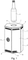
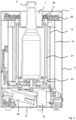
- the glass drinking bottle 2 stands on a sensor device 17, which in the embodiment shown is provided by means of a lower horizontally extending wall section 16.
- the sensor device 17 has a button 18, which is actuated when the glass drinking bottle 2 is in the bottle receiving space 7 on the Sensor device 17 is switched off.
- the sensor device 17 is coupled to a control device 19, which in turn controls the operation of a heating device 20 with several heat radiators 21.
- the several heat radiators 21 are arranged around the bottle receiving space 7 and, in defrosting mode, emit heat radiation directly onto the glass drinking bottle 2 in order to defrost the frozen beverage arranged therein.
- Electrical connection or contact areas 22, 23, for example in the form of bases, are spatially separated from the bottle receiving space 7 by means of the lower horizontal wall section 16 and an upper horizontal wall section.
- An anti-tamper protection 25 extends between an upper horizontal wall section 24 and the housing opening 6, which consists for example of a glass material and prevents the user from inadvertently coming into contact with the heat radiators 21 and the electrical connection and contact area 22, 23 when inserting or removing the glass drinking bottle 2.
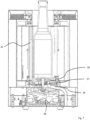
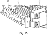
- the device 1 has a thermal insulation and cooling device which is formed with an air conveying device 26 which, in the embodiment shown, is designed as a fan.
- the air conveying device 26 sucks air through air inlets 27a, 27b which, in the embodiment, are formed on the floor and wall sides, into an air duct 28 which extends to an air outlet 29.
- the air duct 28 guides the cooling air past the electrical contact or connection areas 23, as well as through the thermal insulation space 14 and past the electrical contact and connection areas 22 to the air outlet 29 which, in the embodiment shown, is formed in a side wall section by means of openings.
- a bottle guide 32 which in the example shown is formed with glass tubes or rods 33 which are arranged at a distance from one another all around.
- the heat emitters 21 are each protected against twisting by means of a temperature-resistant guide 35, for example a metal guide ( Fig. 9 ). Twisting the heat radiators 21, which can be coated with a white, highly reflective ceramic, can be problematic during operation, since the radiation energy must be directed at the glass drinking bottle 2 in the center of the device 1. If the heat radiators 21 are twisted relative to the position in which the radiation energy is concentrated, the efficiency drops and the energy must also be dissipated as power loss via the housing 3.
- a temperature-resistant guide 35 for example a metal guide ( Fig. 9 ). Twisting the heat radiators 21, which can be coated with a white, highly reflective ceramic, can be problematic during operation, since the radiation energy must be directed at the glass drinking bottle 2 in the center of the device 1. If the heat radiators 21 are twisted relative to the position in which the radiation energy is concentrated, the efficiency drops and the energy must also be dissipated as power loss via the housing 3.
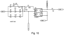
- a connected heat emitter 21 By means of a respective electronic circuit (cf. Fig. 10 , Fig. 11 ) it is detected whether a connected heat emitter 21 is defective.
- a heat emitter 21 is connected to OUT1 and connected to N.
- the capacitor C5 charges with each positive half-wave and drives a light-emitting diode (LED) in the optocoupler U3. A voltage of 0V is present at the Channel1 output.
- LED light-emitting diode
- the Channel1 output is connected to a microcontroller and is evaluated by it.
- An acoustic signal can signal a defect in a heat emitter 21.
- the display 11 can show the user the position of the defective heat emitters 21. If a defined number of defective heat emitters 21 is exceeded, the operation of the device 1 can be stopped and a message about necessary maintenance can be shown on the display 11.
- ceramic materials such as aluminum titanate, aluminum oxide, zirconium oxide, silicon nitride, aluminum silicate or high-temperature resistant engineering plastics such as polytetrafluoroethylene (PTFE), polyetheretherketone (PEEK), polyetherketones (PEK), perfluoroalkoxy polymers (PFA), polyvinylidene fluoride (PVDF), polyethersulfone (PES), polysulfone (PSU), polyamideimide (PAI), polyimide (PI) or polyphenylenesulfone (PPSU) are used.
- PTFE polytetrafluoroethylene
- PEEK polyetheretherketone
- PEK polyetherketones
- PFA perfluoroalkoxy polymers
- PVDF polyvinylidene fluoride
- PES polyethersulfone
- PSU polysulfone
- PAI polyamideimide
- PI polyimide
- PPSU polyphenylenesulfone
- the device 1 has a system for adjusting the heating power when the device 1 overheats in order to avoid forced cooling phases.
- the heating power can be varied during operation using a dimmer, for example the semiconductor relay 40. By periodically switching on and off, less energy flows on average over time, which is why the average power can be significantly reduced. This is necessary if the power loss can no longer be dissipated quickly enough by the fan 26 during continuous operation.
- the heating power can be reduced beforehand and the device 1 can be used permanently and continuously without annoying waiting periods. This offers the user added value and makes the device 1 more user-friendly.
- a software controls the heating power and records the temperatures in the interior 12 of the housing 3. If the temperature in the interior 12 of the housing 3 exceeds one or more threshold values, the heating power can be reduced. By integrating the supplied heating power over time, the software records the amount of energy already supplied as a function of the number of defective heat radiators 21 and the dimming factor ⁇ .
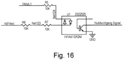
- Device 1 has a zero crossing detection (exemplary circuit with the H11AA1 module in Fig. 16 ) to improve the EMC properties, specifically to avoid EMC loads that are harmful to the network and equipment, and to prevent flickering effects when dimming the power.
- a detection system identifies each individual zero crossing of the 50 Hz alternating current network and thus provides ideal control points for controlling the dimmer. If dimmers are switched on and off at zero crossing, interference with EMC can be minimized.
- the detection of zero crossings also has the great advantage that flickering effects can be avoided or significantly reduced.
- the flickering effects are due to phase shifts and non-mains-synchronous switching of dimmers that switch at zero crossing. It can happen that the right switching time is missed after every n switching operations and the half-wave is mistakenly not switched through. This effect is visible at a much lower frequency of just a few Hz and is therefore particularly disruptive.
Landscapes
- Engineering & Computer Science (AREA)
- Chemical & Material Sciences (AREA)
- Combustion & Propulsion (AREA)
- Physics & Mathematics (AREA)
- Mechanical Engineering (AREA)
- Thermal Sciences (AREA)
- General Engineering & Computer Science (AREA)
- Food Science & Technology (AREA)
- Devices That Are Associated With Refrigeration Equipment (AREA)
- Freezers Or Refrigerated Showcases (AREA)
Priority Applications (3)
| Application Number | Priority Date | Filing Date | Title |
|---|---|---|---|
| RS20250105A RS66475B1 (sr) | 2017-01-13 | 2018-01-15 | Aparat i postupak za odmrzavanje zamrznutog pića u staklenoj boci za piće |
| HRP20250116TT HRP20250116T1 (hr) | 2017-01-13 | 2018-01-15 | Uređaj i postupak za odmrzavanje zamrznutog pića u staklenoj boci za piće |
| SM20250042T SMT202500042T1 (it) | 2017-01-13 | 2018-01-15 | Apparecchio e metodo per scongelare una bevanda ghiacciata in una bottiglia di vetro per bevande |
Applications Claiming Priority (2)
| Application Number | Priority Date | Filing Date | Title |
|---|---|---|---|
| DE102017100647.8A DE102017100647B4 (de) | 2017-01-13 | 2017-01-13 | Vorrichtung und Verfahren zum Auftauen eines gefrorenen Getränks in einer Glastrinkflasche |
| PCT/DE2018/100023 WO2018130252A1 (de) | 2017-01-13 | 2018-01-15 | Vorrichtung und verfahren zum auftauen eines gefrorenen getränks in einer glastrinkflasche |
Publications (3)
| Publication Number | Publication Date |
|---|---|
| EP3568652A1 EP3568652A1 (de) | 2019-11-20 |
| EP3568652C0 EP3568652C0 (de) | 2024-12-04 |
| EP3568652B1 true EP3568652B1 (de) | 2024-12-04 |
Family
ID=61156947
Family Applications (1)
| Application Number | Title | Priority Date | Filing Date |
|---|---|---|---|
| EP18702901.2A Active EP3568652B1 (de) | 2017-01-13 | 2018-01-15 | Vorrichtung und verfahren zum auftauen eines gefrorenen getränks in einer glastrinkflasche |
Country Status (10)
| Country | Link |
|---|---|
| US (1) | US11766142B2 (pl) |
| EP (1) | EP3568652B1 (pl) |
| DE (1) | DE102017100647B4 (pl) |
| ES (1) | ES3010552T3 (pl) |
| HR (1) | HRP20250116T1 (pl) |
| HU (1) | HUE070074T2 (pl) |
| PL (1) | PL3568652T3 (pl) |
| RS (1) | RS66475B1 (pl) |
| SM (1) | SMT202500042T1 (pl) |
| WO (1) | WO2018130252A1 (pl) |
Families Citing this family (4)
| Publication number | Priority date | Publication date | Assignee | Title |
|---|---|---|---|---|
| US11529021B2 (en) | 2018-01-31 | 2022-12-20 | Ember Technologies, Inc. | Actively heated or cooled drinkware container |
| US10722427B2 (en) * | 2018-03-29 | 2020-07-28 | Simon Charles Cantor | Hermetically sealable case for medical device and medicine |
| JP2023500403A (ja) | 2019-11-12 | 2023-01-05 | エンバー テクノロジーズ, インコーポレイテッド | アクティブ温度制御を備えた冷却器 |
| USD1113474S1 (en) * | 2023-06-01 | 2026-02-17 | Shenzhen M&F E-Commerce Co., Ltd. | Temperature controller |
Family Cites Families (19)
| Publication number | Priority date | Publication date | Assignee | Title |
|---|---|---|---|---|
| DE704788C (de) * | 1936-11-29 | 1941-04-07 | Siemens Schuckertwerke Akt Ges | Einrichtung zum Erhitzen von Milch und anderen Fluessigkeiten |
| GB814808A (en) * | 1954-09-16 | 1959-06-10 | Gen Electric | Improvements in insulating wall structures particularly for refrigerator cabinets |
| DE3010889A1 (de) * | 1980-03-21 | 1981-10-01 | Devappa Dr.Ing. R. Zinsser & Ing. K. Prestl, 8420 Kelheim | Vorrichtung zum erwaermen von in behaeltnissen untergebrachten nahrungsmitteln |
| JPH022264Y2 (pl) * | 1985-03-22 | 1990-01-19 | ||
| JPH0373111A (ja) * | 1989-08-11 | 1991-03-28 | Sanyo Electric Co Ltd | 温湯供給器 |
| JPH0373112A (ja) * | 1989-08-11 | 1991-03-28 | Sanyo Electric Co Ltd | 温湯供給器 |
| JPH0386113A (ja) * | 1989-08-31 | 1991-04-11 | Sanyo Electric Co Ltd | 保温装置 |
| US5248870A (en) * | 1991-12-20 | 1993-09-28 | Marlyn Redal | Electric heating device for warming the contents of bottles or other containers |
| JPH0611231A (ja) | 1992-06-29 | 1994-01-21 | Hitachi Ltd | 冷凍冷蔵庫およびその解凍・急冷却方法 |
| IT1289077B1 (it) * | 1996-02-21 | 1998-09-25 | Frigogel 1 Di Ziggiotto Paolo | Apparecchio di riscaldamento e/o raffreddamento di alimenti in genere |
| US20040076409A1 (en) * | 2002-09-16 | 2004-04-22 | Taylor Randall Wade | System and method for warming premature infant feedings |
| US20040140304A1 (en) * | 2003-01-22 | 2004-07-22 | Leyendecker Kurt Philip | Baby bottle chiller/warmer and method of use |
| US7089749B1 (en) * | 2003-08-20 | 2006-08-15 | Robin Contino | Thermoelectrically heated/cooled cupholder system |
| TW200518739A (en) * | 2003-10-07 | 2005-06-16 | Combi Corp | Apparatus for heating baby formula pot and method of operating the same |
| WO2006090996A1 (en) | 2005-02-22 | 2006-08-31 | Daewoo Electronics Corporation | Multi-functional child care storage |
| GB0917583D0 (en) * | 2009-10-08 | 2009-11-25 | Jelley Simon P | Hygienic non-contact rapid heat transfer device |
| US20110147374A1 (en) * | 2009-12-22 | 2011-06-23 | Dbk David + Baader Gmbh | Electric heating apparatus for heating infant food by means of electromagnetic radiation |
| US9480363B2 (en) | 2010-09-09 | 2016-11-01 | Thomas Delattre | Baby bottle warmer |
| US9782036B2 (en) * | 2015-02-24 | 2017-10-10 | Ember Technologies, Inc. | Heated or cooled portable drinkware |
-
2017
- 2017-01-13 DE DE102017100647.8A patent/DE102017100647B4/de active Active
-
2018
- 2018-01-15 US US16/477,699 patent/US11766142B2/en active Active
- 2018-01-15 EP EP18702901.2A patent/EP3568652B1/de active Active
- 2018-01-15 HR HRP20250116TT patent/HRP20250116T1/hr unknown
- 2018-01-15 WO PCT/DE2018/100023 patent/WO2018130252A1/de not_active Ceased
- 2018-01-15 HU HUE18702901A patent/HUE070074T2/hu unknown
- 2018-01-15 RS RS20250105A patent/RS66475B1/sr unknown
- 2018-01-15 ES ES18702901T patent/ES3010552T3/es active Active
- 2018-01-15 SM SM20250042T patent/SMT202500042T1/it unknown
- 2018-01-15 PL PL18702901.2T patent/PL3568652T3/pl unknown
Also Published As
| Publication number | Publication date |
|---|---|
| RS66475B1 (sr) | 2025-03-31 |
| US11766142B2 (en) | 2023-09-26 |
| SMT202500042T1 (it) | 2025-03-12 |
| US20190357709A1 (en) | 2019-11-28 |
| EP3568652C0 (de) | 2024-12-04 |
| ES3010552T3 (en) | 2025-04-03 |
| DE102017100647B4 (de) | 2022-09-01 |
| WO2018130252A1 (de) | 2018-07-19 |
| PL3568652T3 (pl) | 2025-03-10 |
| HRP20250116T1 (hr) | 2025-03-28 |
| HUE070074T2 (hu) | 2025-05-28 |
| EP3568652A1 (de) | 2019-11-20 |
| DE102017100647A1 (de) | 2018-07-19 |
Similar Documents
| Publication | Publication Date | Title |
|---|---|---|
| EP3568652B1 (de) | Vorrichtung und verfahren zum auftauen eines gefrorenen getränks in einer glastrinkflasche | |
| DE4130337C2 (de) | Verfahren zum Betrieb einer elektrischen Heizeinheit und elektrische Heizeinheit | |
| AT390137B (de) | Elektrisches kochgeraet | |
| EP0265635B1 (de) | Strahlheizkörper | |
| EP3327353A1 (de) | Heizungsanordnung | |
| DE2627373B2 (de) | Signaleinrichtung an Kochgeräten mit einer Glaskeramikkochfläche | |
| DE19701640A1 (de) | Kontaktwärmeübertragendes Kochsystem mit einer Elektro-Kochplatte | |
| EP0035254B1 (de) | Elektrische Heizeinrichtung für Herde oder Kochplatten | |
| WO2011124354A1 (de) | Led-leuchtmittel | |
| DE202015105700U1 (de) | Vielzweckerhitzer | |
| EP0371295B1 (de) | Strahlungs-Heizkörper | |
| EP2538827A1 (de) | Vorrichtung zum erwärmen von flüssigkeiten | |
| DE2164162A1 (de) | Elektrokochgeraet | |
| KR20090004305U (ko) | 필름히터와 이를 부착한 루버 | |
| EP1912545B1 (en) | An electric cooking appliance comprising a removable bowl | |
| EP0913646B1 (de) | Herd mit gekühlter Beleuchtungseinrichtung | |
| CN205377102U (zh) | 一种防尘散热开关柜 | |
| DE19526093C5 (de) | Kochmulde mit einem Steuersensor | |
| DE102009049259A1 (de) | Friteuse | |
| WO2017097780A1 (de) | Strahlungsgrill | |
| EP3430324B1 (de) | Temperierkörper-anordnung mit flexiblen betriebsarten | |
| EP0727618A2 (de) | Back-/Bratofen mit einem thermostatgesteuerten Motorlüfter | |
| DE19820108C2 (de) | Anordnung eines wärmeleitenden keramischen Trägers mit einem Heizkörper als Kochzone in einer Aussparung einer Kochfläche | |
| EP0754918B1 (de) | Kochfläche mit einer Sensoranordung für Kochstellenheizelemente. | |
| WO2003037149A1 (de) | Mobiles universalkochgerät |
Legal Events
| Date | Code | Title | Description |
|---|---|---|---|
| REG | Reference to a national code |
Ref country code: HR Ref legal event code: TUEP Ref document number: P20250116T Country of ref document: HR |
|
| STAA | Information on the status of an ep patent application or granted ep patent |
Free format text: STATUS: UNKNOWN |
|
| STAA | Information on the status of an ep patent application or granted ep patent |
Free format text: STATUS: THE INTERNATIONAL PUBLICATION HAS BEEN MADE |
|
| PUAI | Public reference made under article 153(3) epc to a published international application that has entered the european phase |
Free format text: ORIGINAL CODE: 0009012 |
|
| STAA | Information on the status of an ep patent application or granted ep patent |
Free format text: STATUS: REQUEST FOR EXAMINATION WAS MADE |
|
| 17P | Request for examination filed |
Effective date: 20190627 |
|
| AK | Designated contracting states |
Kind code of ref document: A1 Designated state(s): AL AT BE BG CH CY CZ DE DK EE ES FI FR GB GR HR HU IE IS IT LI LT LU LV MC MK MT NL NO PL PT RO RS SE SI SK SM TR |
|
| AX | Request for extension of the european patent |
Extension state: BA ME |
|
| DAV | Request for validation of the european patent (deleted) | ||
| DAX | Request for extension of the european patent (deleted) | ||
| STAA | Information on the status of an ep patent application or granted ep patent |
Free format text: STATUS: EXAMINATION IS IN PROGRESS |
|
| 17Q | First examination report despatched |
Effective date: 20210528 |
|
| GRAP | Despatch of communication of intention to grant a patent |
Free format text: ORIGINAL CODE: EPIDOSNIGR1 |
|
| STAA | Information on the status of an ep patent application or granted ep patent |
Free format text: STATUS: GRANT OF PATENT IS INTENDED |
|
| INTG | Intention to grant announced |
Effective date: 20240708 |
|
| GRAS | Grant fee paid |
Free format text: ORIGINAL CODE: EPIDOSNIGR3 |
|
| GRAA | (expected) grant |
Free format text: ORIGINAL CODE: 0009210 |
|
| STAA | Information on the status of an ep patent application or granted ep patent |
Free format text: STATUS: THE PATENT HAS BEEN GRANTED |
|
| AK | Designated contracting states |
Kind code of ref document: B1 Designated state(s): AL AT BE BG CH CY CZ DE DK EE ES FI FR GB GR HR HU IE IS IT LI LT LU LV MC MK MT NL NO PL PT RO RS SE SI SK SM TR |
|
| REG | Reference to a national code |
Ref country code: GB Ref legal event code: FG4D Free format text: NOT ENGLISH |
|
| REG | Reference to a national code |
Ref country code: CH Ref legal event code: EP |
|
| REG | Reference to a national code |
Ref country code: DE Ref legal event code: R096 Ref document number: 502018015383 Country of ref document: DE |
|
| REG | Reference to a national code |
Ref country code: IE Ref legal event code: FG4D Free format text: LANGUAGE OF EP DOCUMENT: GERMAN |
|
| U01 | Request for unitary effect filed |
Effective date: 20250102 |
|
| U07 | Unitary effect registered |
Designated state(s): AT BE BG DE DK EE FI FR IT LT LU LV MT NL PT RO SE SI Effective date: 20250114 |
|
| REG | Reference to a national code |
Ref country code: HR Ref legal event code: ODRP Ref document number: P20250116T Country of ref document: HR Payment date: 20250303 Year of fee payment: 8 |
|
| REG | Reference to a national code |
Ref country code: GR Ref legal event code: EP Ref document number: 20250400217 Country of ref document: GR Effective date: 20250314 |
|
| REG | Reference to a national code |
Ref country code: HR Ref legal event code: T1PR Ref document number: P20250116 Country of ref document: HR |
|
| U20 | Renewal fee for the european patent with unitary effect paid |
Year of fee payment: 8 Effective date: 20250224 |
|
| REG | Reference to a national code |
Ref country code: SK Ref legal event code: T3 Ref document number: E 45976 Country of ref document: SK |
|
| PGFP | Annual fee paid to national office [announced via postgrant information from national office to epo] |
Ref country code: AL Payment date: 20250305 Year of fee payment: 8 |
|
| REG | Reference to a national code |
Ref country code: HU Ref legal event code: AG4A Ref document number: E070074 Country of ref document: HU |
|
| PLBE | No opposition filed within time limit |
Free format text: ORIGINAL CODE: 0009261 |
|
| STAA | Information on the status of an ep patent application or granted ep patent |
Free format text: STATUS: NO OPPOSITION FILED WITHIN TIME LIMIT |
|
| REG | Reference to a national code |
Ref country code: CH Ref legal event code: L10 Free format text: ST27 STATUS EVENT CODE: U-0-0-L10-L00 (AS PROVIDED BY THE NATIONAL OFFICE) Effective date: 20251015 |
|
| PGFP | Annual fee paid to national office [announced via postgrant information from national office to epo] |
Ref country code: MK Payment date: 20250228 Year of fee payment: 8 |
|
| 26N | No opposition filed |
Effective date: 20250905 |
|
| PGFP | Annual fee paid to national office [announced via postgrant information from national office to epo] |
Ref country code: PL Payment date: 20251227 Year of fee payment: 9 |
|
| PGFP | Annual fee paid to national office [announced via postgrant information from national office to epo] |
Ref country code: SK Payment date: 20251229 Year of fee payment: 9 |
|
| PGFP | Annual fee paid to national office [announced via postgrant information from national office to epo] |
Ref country code: RS Payment date: 20251226 Year of fee payment: 9 |
|
| REG | Reference to a national code |
Ref country code: HR Ref legal event code: ODRP Ref document number: P20250116 Country of ref document: HR Payment date: 20251230 Year of fee payment: 9 |
|
| REG | Reference to a national code |
Ref country code: CH Ref legal event code: U11 Free format text: ST27 STATUS EVENT CODE: U-0-0-U10-U11 (AS PROVIDED BY THE NATIONAL OFFICE) Effective date: 20260201 |
|
| PGFP | Annual fee paid to national office [announced via postgrant information from national office to epo] |
Ref country code: HU Payment date: 20260115 Year of fee payment: 9 |
|
| U20 | Renewal fee for the european patent with unitary effect paid |
Year of fee payment: 9 Effective date: 20260126 |
|
| PGFP | Annual fee paid to national office [announced via postgrant information from national office to epo] |
Ref country code: SM Payment date: 20260126 Year of fee payment: 9 |
|
| PGFP | Annual fee paid to national office [announced via postgrant information from national office to epo] |
Ref country code: GB Payment date: 20260126 Year of fee payment: 9 |
|
| PGFP | Annual fee paid to national office [announced via postgrant information from national office to epo] |
Ref country code: ES Payment date: 20260210 Year of fee payment: 9 Ref country code: MC Payment date: 20260120 Year of fee payment: 9 |
|
| PGFP | Annual fee paid to national office [announced via postgrant information from national office to epo] |
Ref country code: NO Payment date: 20260120 Year of fee payment: 9 Ref country code: IE Payment date: 20260120 Year of fee payment: 9 |
|
| PGFP | Annual fee paid to national office [announced via postgrant information from national office to epo] |
Ref country code: HR Payment date: 20260121 Year of fee payment: 9 |
|
| PGFP | Annual fee paid to national office [announced via postgrant information from national office to epo] |
Ref country code: IS Payment date: 20260128 Year of fee payment: 9 |
|
| PGFP | Annual fee paid to national office [announced via postgrant information from national office to epo] |
Ref country code: TR Payment date: 20260107 Year of fee payment: 9 |
|
| PGFP | Annual fee paid to national office [announced via postgrant information from national office to epo] |
Ref country code: CH Payment date: 20260201 Year of fee payment: 9 Ref country code: CZ Payment date: 20260109 Year of fee payment: 9 |
|
| PGFP | Annual fee paid to national office [announced via postgrant information from national office to epo] |
Ref country code: GR Payment date: 20260120 Year of fee payment: 9 Ref country code: CY Payment date: 20251210 Year of fee payment: 9 |