EP3568239B1 - Kartuschenpresse - Google Patents
Kartuschenpresse Download PDFInfo
- Publication number
- EP3568239B1 EP3568239B1 EP18700876.8A EP18700876A EP3568239B1 EP 3568239 B1 EP3568239 B1 EP 3568239B1 EP 18700876 A EP18700876 A EP 18700876A EP 3568239 B1 EP3568239 B1 EP 3568239B1
- Authority
- EP
- European Patent Office
- Prior art keywords
- latching
- locking
- push
- push rod
- press according
- Prior art date
- Legal status (The legal status is an assumption and is not a legal conclusion. Google has not performed a legal analysis and makes no representation as to the accuracy of the status listed.)
- Active
Links
Images






Classifications
-
- B—PERFORMING OPERATIONS; TRANSPORTING
- B05—SPRAYING OR ATOMISING IN GENERAL; APPLYING FLUENT MATERIALS TO SURFACES, IN GENERAL
- B05C—APPARATUS FOR APPLYING FLUENT MATERIALS TO SURFACES, IN GENERAL
- B05C17/00—Hand tools or apparatus using hand held tools, for applying liquids or other fluent materials to, for spreading applied liquids or other fluent materials on, or for partially removing applied liquids or other fluent materials from, surfaces
- B05C17/005—Hand tools or apparatus using hand held tools, for applying liquids or other fluent materials to, for spreading applied liquids or other fluent materials on, or for partially removing applied liquids or other fluent materials from, surfaces for discharging material from a reservoir or container located in or on the hand tool through an outlet orifice by pressure without using surface contacting members like pads or brushes
- B05C17/01—Hand tools or apparatus using hand held tools, for applying liquids or other fluent materials to, for spreading applied liquids or other fluent materials on, or for partially removing applied liquids or other fluent materials from, surfaces for discharging material from a reservoir or container located in or on the hand tool through an outlet orifice by pressure without using surface contacting members like pads or brushes with manually mechanically or electrically actuated piston or the like
- B05C17/0116—Hand tools or apparatus using hand held tools, for applying liquids or other fluent materials to, for spreading applied liquids or other fluent materials on, or for partially removing applied liquids or other fluent materials from, surfaces for discharging material from a reservoir or container located in or on the hand tool through an outlet orifice by pressure without using surface contacting members like pads or brushes with manually mechanically or electrically actuated piston or the like characterised by the piston driving means
- B05C17/012—Stepwise advancing mechanism, e.g. pawl and ratchets
- B05C17/0123—Lever actuated
- B05C17/0126—Lever actuated comprising an element, e.g. an arc compensating element, articulated at one end on the lever and at the other end on the piston rod driving means, e.g. a pawl
-
- B—PERFORMING OPERATIONS; TRANSPORTING
- B05—SPRAYING OR ATOMISING IN GENERAL; APPLYING FLUENT MATERIALS TO SURFACES, IN GENERAL
- B05C—APPARATUS FOR APPLYING FLUENT MATERIALS TO SURFACES, IN GENERAL
- B05C17/00—Hand tools or apparatus using hand held tools, for applying liquids or other fluent materials to, for spreading applied liquids or other fluent materials on, or for partially removing applied liquids or other fluent materials from, surfaces
- B05C17/005—Hand tools or apparatus using hand held tools, for applying liquids or other fluent materials to, for spreading applied liquids or other fluent materials on, or for partially removing applied liquids or other fluent materials from, surfaces for discharging material from a reservoir or container located in or on the hand tool through an outlet orifice by pressure without using surface contacting members like pads or brushes
- B05C17/00576—Hand tools or apparatus using hand held tools, for applying liquids or other fluent materials to, for spreading applied liquids or other fluent materials on, or for partially removing applied liquids or other fluent materials from, surfaces for discharging material from a reservoir or container located in or on the hand tool through an outlet orifice by pressure without using surface contacting members like pads or brushes characterised by the construction of a piston as pressure exerting means, or of the co-operating container
-
- B—PERFORMING OPERATIONS; TRANSPORTING
- B05—SPRAYING OR ATOMISING IN GENERAL; APPLYING FLUENT MATERIALS TO SURFACES, IN GENERAL
- B05C—APPARATUS FOR APPLYING FLUENT MATERIALS TO SURFACES, IN GENERAL
- B05C17/00—Hand tools or apparatus using hand held tools, for applying liquids or other fluent materials to, for spreading applied liquids or other fluent materials on, or for partially removing applied liquids or other fluent materials from, surfaces
- B05C17/005—Hand tools or apparatus using hand held tools, for applying liquids or other fluent materials to, for spreading applied liquids or other fluent materials on, or for partially removing applied liquids or other fluent materials from, surfaces for discharging material from a reservoir or container located in or on the hand tool through an outlet orifice by pressure without using surface contacting members like pads or brushes
- B05C17/01—Hand tools or apparatus using hand held tools, for applying liquids or other fluent materials to, for spreading applied liquids or other fluent materials on, or for partially removing applied liquids or other fluent materials from, surfaces for discharging material from a reservoir or container located in or on the hand tool through an outlet orifice by pressure without using surface contacting members like pads or brushes with manually mechanically or electrically actuated piston or the like
-
- B—PERFORMING OPERATIONS; TRANSPORTING
- B05—SPRAYING OR ATOMISING IN GENERAL; APPLYING FLUENT MATERIALS TO SURFACES, IN GENERAL
- B05C—APPARATUS FOR APPLYING FLUENT MATERIALS TO SURFACES, IN GENERAL
- B05C17/00—Hand tools or apparatus using hand held tools, for applying liquids or other fluent materials to, for spreading applied liquids or other fluent materials on, or for partially removing applied liquids or other fluent materials from, surfaces
- B05C17/005—Hand tools or apparatus using hand held tools, for applying liquids or other fluent materials to, for spreading applied liquids or other fluent materials on, or for partially removing applied liquids or other fluent materials from, surfaces for discharging material from a reservoir or container located in or on the hand tool through an outlet orifice by pressure without using surface contacting members like pads or brushes
- B05C17/01—Hand tools or apparatus using hand held tools, for applying liquids or other fluent materials to, for spreading applied liquids or other fluent materials on, or for partially removing applied liquids or other fluent materials from, surfaces for discharging material from a reservoir or container located in or on the hand tool through an outlet orifice by pressure without using surface contacting members like pads or brushes with manually mechanically or electrically actuated piston or the like
- B05C17/014—Hand tools or apparatus using hand held tools, for applying liquids or other fluent materials to, for spreading applied liquids or other fluent materials on, or for partially removing applied liquids or other fluent materials from, surfaces for discharging material from a reservoir or container located in or on the hand tool through an outlet orifice by pressure without using surface contacting members like pads or brushes with manually mechanically or electrically actuated piston or the like comprising means for preventing oozing
-
- B—PERFORMING OPERATIONS; TRANSPORTING
- B05—SPRAYING OR ATOMISING IN GENERAL; APPLYING FLUENT MATERIALS TO SURFACES, IN GENERAL
- B05C—APPARATUS FOR APPLYING FLUENT MATERIALS TO SURFACES, IN GENERAL
- B05C17/00—Hand tools or apparatus using hand held tools, for applying liquids or other fluent materials to, for spreading applied liquids or other fluent materials on, or for partially removing applied liquids or other fluent materials from, surfaces
- B05C17/005—Hand tools or apparatus using hand held tools, for applying liquids or other fluent materials to, for spreading applied liquids or other fluent materials on, or for partially removing applied liquids or other fluent materials from, surfaces for discharging material from a reservoir or container located in or on the hand tool through an outlet orifice by pressure without using surface contacting members like pads or brushes
- B05C17/00583—Hand tools or apparatus using hand held tools, for applying liquids or other fluent materials to, for spreading applied liquids or other fluent materials on, or for partially removing applied liquids or other fluent materials from, surfaces for discharging material from a reservoir or container located in or on the hand tool through an outlet orifice by pressure without using surface contacting members like pads or brushes the container for the material to be dispensed being deformable
Definitions
- the invention relates to a cartridge press with an actuating housing which has a handle, the movement of which relative to the actuating housing in an actuating direction results in a displacement of a pressure rod displaceably mounted in the actuating housing in a pressure direction, and with a receiving device for receiving a pasty mass which can be pressed out of a hose or a cartridge by the displacement of the pressure rod, wherein the receiving device is rotatably fastened to the actuating housing, for which purpose a fastening base having an opening for the passage of the pressure rod projects into a fastening opening and is there tied axially relative to the pressure rod with a form-fitting fastening means.
- the invention further relates to a cartridge press with an actuating housing which has a handle, the movement of which relative to the actuating housing in an actuating direction results in a displacement of a pressure rod in a pressure direction, with a receiving device for receiving a pasty mass which can be pressed out of a hose or a cartridge by the displacement of the pressure rod and with a release lever arranged on a first side of the pressure rod on the actuating housing for interacting with a push-back locking element, and with a changeover switch which can be brought from a first switching position, in which the push-back locking element assumes an operative position relative to the pressure rod, into a second switching position, in which the push-back locking element assumes an inoperative position relative to the pressure rod.
- a cartridge press of the generic type relating to a first aspect of the invention describes the US 5,887,765 .
- the cartridge press has an actuating housing with a handle which is pivotably attached to the actuating housing and can be pivoted relative to a handle.
- the handle engages a driving member which clamps itself onto a push rod so that the push rod can be gradually moved in a pressure direction.
- a threaded piece with an opening for the push rod to pass through is screwed with its external thread into an internal thread of the actuating housing in order to form-fit a receiving device in the form of a tray for receiving a cartridge to the actuating housing.
- the receiving device can hold a cartridge with a pasty mass which is squeezed out by moving the push rod.
- the US 5,431, 654 describes a cartridge ejection device in which the actuating housing has an arcuate groove into which a radially outwardly projecting collar of the receiving device can be inserted in order to thereby connect the receiving device to the actuating housing in a form-fitting and rotatable manner.
- a cartridge press is already known in which a mounting base is located on the actuator housing, onto which a connection profile in the form of an arcuate ring groove and a receiving device can be pushed in the radial direction.
- the pressure rod secures the fastening of the receiving device to the actuator housing.
- the DE 10 2014 116 514 describes a cartridge press of a second aspect of the invention, in which a changeover switch is provided with which a push-back locking member can be brought between an active position and an inactive position.
- the DE 10 2014 105 935 A1 describes a cartridge press in which the angle between the handle and a handgrip can be adjusted. This is done with an adjustable eccentric bushing.
- EP 2 878 383 A1 and US 2012/118913 other cartridge presses are described.
- the invention is based on the object of specifying measures by means of which a cartridge press is further developed in a manner that is advantageous in use.
- the form-locking means with which the receiving device is tied to the actuating housing is further developed.
- a fastening base engages in a fastening opening.
- the fastening opening opens into a radial shaft which extends in the radial direction relative to the direction of extension of the push rod.
- a locking slider which has a locking flank can be inserted into the radial shaft. In a form-locking position, the locking flank engages in an annular groove of the fastening base.
- the fastening base is rotatable in the fastening opening so that the receiving device can be rotated about the axis formed by the push rod.
- the fastening base is preferably formed by the receiving device and is in particular connected to an end piece of the receiving device using the same material.
- the radial shaft has two walls that run parallel to one another, the distance between which preferably corresponds to the material thickness of the restraining slide. Both walls of the radial shaft can have an opening. The two openings can be aligned with one another.
- the fastening base can be inserted into both openings.
- the annular groove then extends in the area of the radial shaft.
- the radial shaft is preferably formed by the actuating housing and has an opening that points to a first side of the actuating housing. The handle or a release lever is arranged on this first side.
- the release lever can extend in front of the opening of the radial shaft so that the restraining slide can only be pushed into the radial shaft when the release lever is pivoted back.
- the restraining flank of the restraining slide is preferably formed by the edge of a U-shaped cut in the restraining slide, which is preferably made of steel, die-cast or a similar material.
- the fastening base is subjected to spring force in the axial direction of the push rod by a spring. When the fastening base is inserted into the fastening opening, this compression spring must be tensioned.
- the compression spring can be a compression spring associated with a push-back locking element, which is supported on an end face of the fastening base and through which the push rod passes.
- One end of the spring can be arranged in a depression in the end face of the fastening base.
- the other end can be supported on the push-back locking element formed by a steel plate.
- An end cap forming the end piece, from which the fastening base preferably originates, can form an end wall which rests in contact with an end wall of the actuating housing.
- the receiving device can have a receiving body which is designed as a tube or as a trough.
- a pressure plate attached to the end of the push rod can be moved in the tube or the trough, with which a hose containing the pasty mass or a piston of a cartridge can be moved in such a way that is that the pasty mass is pressed out through an opening of a head piece, which is opposite the end piece. This is preferably done by a nozzle.
- the two opposite openings of a tubular receiving body are preferably closed by the end piece or head piece.
- the head piece and the end piece are connected to the receiving body by means of a form-fitting means. This can be a bayonet closure or a thread.
- a second aspect of the invention relates to a further development of a changeover switch which can be moved from a first switching position, in which a push-back locking element assumes an active position on the push rod, to a second switching position, in which the push-back locking element assumes an inactive position relative to the push rod.
- the push rod can be moved in the direction of pressure by gradually operating the handle.
- the push-back locking element prevents the push rod from being moved backwards. Only when the push-back locking element is moved by pivoting a release lever can the push rod be moved against the direction of pressure.
- the inactive position the push rod can also be moved back without operating the release lever.
- the inactive position is particularly advantageous in use when the pasty mass is compressed when it is squeezed out and the compression of the pasty mass can lead to dripping. In the inactive position, the pasty mass can relax again after the handle has been operated.
- the changeover switch is located on the opposite side of the release lever relative to the push rod.
- the release lever can have an extension which acts on the push-back locking element, which is preferably formed by a plate, on a first side.
- a section of the changeover switch engages the push-back locking member.
- the section is an extension or an eccentric section and forms a projection that projects radially from the pivot axis of the changeover switch.
- the section preferably rests on the push-back locking member in the active position.
- the push-back locking member preferably has two broad side surfaces facing away from one another. One of the two broad side surfaces faces in the direction of pressure.
- the section of the changeover switch and the eccentric projection of the release lever engage the broad side surface facing away from it, the push-back locking member being supported on the release lever and on the changeover switch by the force of a spring and extending essentially in a plane transverse to the axis of the push rod.
- a handle width adjustment is also provided.
- an eccentric sleeve is mounted on a pivot axis around which the handle can be pivoted.
- the eccentric sleeve can be rotated using a changeover lever in order to change the angle between the handle and the handle.
- the handle has a drive arm which projects into the actuating housing and which engages at least one driving element which can assume a driving position relative to the push rod in order to gradually move the push rod in the direction of pressure by pivoting the handle.
- a return spring is provided which moves the driving element back to its original position.
- the receiving device preferably consists of a receiving body, which in particular has the shape of a tube that is open on both sides.
- One end of the receiving body is inserted into a receiving opening of an end piece.
- the end piece has a sleeve section into which a first end of the receiving body is inserted.
- An axial binding of the receiving body to the end piece is provided.
- a second end of the receiving body is inserted into a receiving opening of a head piece, which has an opening for the pasty mass to pass through.
- the opening can in particular accommodate a nozzle.
- the head piece has a sleeve section into which the end of the receiving body is inserted.
- the sleeve section of the end piece and the sleeve section of the head piece are each detachably connected to the receiving body via a bayonet-like connection.
- the head piece or the end piece In order to axially bind the head piece or the end piece to the receiving body, the head piece or the end piece must be rotated by an angle of rotation after the end of the receiving body has been inserted into the sleeve section, so that the binding means for axial binding follow one another in the axial direction.
- locking means are provided.
- locking projections are provided which interact with counter-locking projections.
- the counter-locking projections preferably form locking recesses into which the locking projections can engage.
- the locking projections can be formed by the receiving body and the counter-locking projections or locking recesses can be formed by the sleeve sections.
- the locking means form locking beads which engage in locking grooves, with the receiving body preferably forming radially outward-pointing locking beads and the sleeve sections forming radially inward-pointing locking grooves.
- a torque must be applied to the sleeve section.
- the two locking connections are designed in such a way that a lower torque must be applied to release the head piece from the receiving body than to release the receiving body from the end piece.
- the locking connection between the end piece and the receiving body a larger number of locking beads engage in locking recesses than in the locking connection between the head piece and the receiving body.
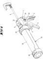
- the cartridge presses shown in the drawings have an actuating housing 1, which is made of plastic or another material, such as metal, and on which a Handle 2 in the direction of a handle 3 is also pivotally connected to a release lever 5.
- a pressure rod 4 is mounted in the actuating housing 1 so that it can move in the direction of its axis.
- a handle and a stop spring are located on the rear end of the pressure rod 4.
- a pressure plate 27 is attached to the pressure-side end of the pressure rod 4.
- the end of the pressure rod 4 can have a circumferential groove in which a locking ring is inserted.
- a thread of the pressure rod 4 engages in a thread of the pressure plate 27.
- the edge 27' of the pressure plate 27 engages in a curved groove 36 of a pressure stamp 28 (see Figures 8 and 9 ).
- the pivot axis 35 is inserted into an eccentric bushing 34 which is mounted in a bearing cavity of the housing.
- the eccentric bushing 34 can be rotated by means of a changeover lever 33 attached to the eccentric bushing 34 in order to change the angle that the handle 2 assumes in relation to the handle 3.
- the handle 2 is essentially a two-armed lever with a long lever arm that can be grasped by the fingers of a user's hand and a short lever arm that engages a driving member 8 consisting of two steel plates.
- a driving member 8 consisting of two steel plates.
- the driving member 8 is tilted.
- the pressure rod 4 passes through an opening in the driving member 8, so that the driving member 8 tilts relative to the pressure rod 4 when tilted.
- a displacement of the driving member 8 by pivoting the handle 2 thus results in a linear displacement of the pressure rod 4 in the pressure direction, in which the pressure plate 27 is displaced within the receiving device 10 in the direction of a grommet 30.
- the release lever 5 also has a first, longer arm that can be grasped by a finger of a user's hand, and a short lever arm that forms an eccentric extension that engages a push-back locking member 9.
- the push-back locking member 9 can be a steel plate that has an opening through which the push rod 4 passes. If the push-back locking member 9 assumes a tilted position relative to the push rod 4, the push rod 4 can only be displaced in the pressure direction. If, however, the push-back locking member 9 does not assume a tilted position, the push rod 4 can be displaced axially in both directions relative to the push-back locking member 9.
- the actuating housing 1 has a first side on which the release lever 5 and the handle 2 as well as the handle 3 are arranged. A second side is opposite this first side.
- the push rod 4 extends between the two sides and the push-back locking element 9 is located.
- An actuating section of a changeover switch 6 protrudes from the second side of the actuating housing 1.
- the changeover switch 6 can be switched from a first switching position, which is in the Fig. 2 shown, can be brought into a second switching position, which is in the Fig. 11 is shown. In the first switching position, the push-back locking member 9 assumes an active position. In this position, the push rod 4 can only be moved against the pressure direction by actuating the release lever 5.
- the push-back locking member 9 is thereby its side opposite the release lever 5 is held in the axial direction.
- the eccentric section 31 presses the edge of the push-back locking element 9 against a housing wall of the actuating housing 1.
- a spring 22 acts on the push-back locking member 9 in such a way that it assumes a tilted position, so that the push rod 4 becomes wedged in the opening of the push-back locking member 9. If the release lever 5 is pivoted, the push-back locking member 9 is brought out of the tilted position against the force of the spring 22.
- the return locking element 9 is also brought out of the tilted position when the changeover switch 6 is moved from the Fig. 2 shown first switching position to the one in Fig. 11 shown second switching position. Then the push-back locking member 9 acted upon by the spring 22 is supported on a section of the changeover switch 6 and on the release lever 5 in such a way that the push rod 4 can be moved freely through the opening of the push-back locking member 9.
- the push-back locking member 9 can thus assume two different inoperative positions, in each of which the push-back locking member 9 extends approximately transversely to the direction of extension of the push rod 4. In a first inoperative position, it is pressed against the housing wall by the projection of the changeover switch 6, designated as the eccentric section 31, and by the short arm of the release lever 5 when the latter is actuated. In the second inoperative position, the push-back locking member 9 is spaced from the housing wall 37 and is held in a parallel position to the housing wall 37 by a section of the changeover switch 6 and by the non-actuated release lever 5.
- the receiving device 10 is rotatably connected to the actuating housing 1.
- the axis of rotation is formed by the push rod 4.
- the push rod 4 passes through a fastening opening 13 of an end wall 20 of the actuating housing 1 in the axial center.
- the fastening opening 13 has a circular outline.
- a radial shaft 14 of the actuating housing 1 adjoins the fastening opening 13.
- the radial shaft 14 extends in the radial direction relative to the push rod 4 and has an opening which is located in the area of the actuating section of the release lever 5.
- the receiving device 10 has a fastening base 11 which originates from an end wall 21 of the receiving device 10.
- the fastening base 11 has an end face 11' which has a recess 23 and an opening 12 through which the pressure rod 4 is guided.
- the mounting base 11 is inserted into the mounting opening 13 to attach the receiving device 10 to the actuator housing 1.
- the mounting base 11 has an outer diameter that corresponds to the inner diameter of the opening 12.
- the fastening base 11 has a circumferential ring groove 16.
- the circumferential ring groove 16 When inserted, the circumferential ring groove 16 is located in the area of the radial shaft 14.
- the end wall 20 can rest against the end wall 21.
- the two end walls 20, 21 can also be spaced apart from one another.
- the radial shaft has two walls spaced apart from one another, namely the end wall 20 and the wall 38 running parallel to it, which has an opening 39 in which a section of the fastening base 11 is inserted, the opening 39 being aligned with the opening 13.
- the edges of the U-shaped recess form a locking flank 17, which in a positive engagement position engages in the annular groove 16, so that the fastening base 11 is axially bound in the opening 12 and thus the receiving device 10 is axially bound to the actuating housing 1.
- the receiving device 10 can be rotated by any angle of rotation relative to the actuator housing 1.
- the restraining slide 15 is inserted into the radial shaft 14 in such a way that it can only be removed from its positive engagement position with the aid of a tool, for example with the blade of a screwdriver.
- a locking projection 19' of a locking tongue 19 must be moved from a rear grip position.
- the locking projection 19' protrudes into a locking opening 18 of the restraining slide 15, with the locking opening 18 being opposite the restraining opening 17.
- the locking tongue 15 is cut free from the wall 38.
- the spring 22, which acts on the push-back locking element 9 and through which the push rod 4 is inserted, is supported on the front surface of the actuating base 11. It lies on the bottom of the recess 23.
- the receiving device 10 has an end piece 24 which is connected in a form-fitting manner, for example via a bayonet connection, to a tubular receiving body 25.
- the end piece 24 closes a tube opening and forms the end wall 21 and the fastening base 11 protruding from the end wall 21 in a uniform material and is preferably designed as a plastic part for this purpose.
- the other pipe opening of the receiving body 25 is closed by a head piece 26, which can carry the nozzle 30.
- the end piece 24' is seated on a trough-shaped receiving body 25' for receiving a cartridge.
- the head end of the receiving body 25' has a notch for inserting the spout 30.
- the Figures 12 to 13a show the connection of the head piece 26 or the end piece 24 to one end of the receiving body 25 designed as a tube.
- This is a bayonet connection, i.e. a plug-in rotary connection.
- the receiving body 25 is inserted into a sleeve section of the end piece 24 or the head piece 26.
- the sleeve section or the end section of the receiving body 25 has restraining elements which, after a partial rotation of the end piece 24 or head piece 26 relative to the receiving body 25, come into an axial position one behind the other so that they axially bind the end piece 24 or head piece 26 to the receiving body 25.
- locking means In order to hold the end piece 24 or the head piece 26 in the bound end position, locking means are provided which interact in the rotational end position to produce a rotational inhibition.
- the locking means have locking elements in particular which engage with one another.
- the locking elements can be formed by toothed sections of the head piece 26, the end piece 24 and the two ends of the receiving body 25.
- the outer wall of the receiving body 25 has locking beads 40 pointing radially outwards.
- Four locking beads are arranged next to each other in the circumferential direction.
- the inner wall of the sleeve section of the end piece 24 or head piece 26 has counter-locking elements which are connected to the locking elements.
- the counter-locking elements are formed by locking grooves 41 and 42, into which the locking beads 40 enter.
- the end piece 24 has four locking grooves 41.
- the number of locking beads 40 here corresponds to the number of locking grooves 41.
- the Fig. 13 or Fig. 13a The head piece 26 shown, however, has a smaller number of locking grooves 42 than the end piece 24. In the exemplary embodiment, there are two locking grooves 42, into which only two of the locking beads 40 engage.
- the rotation-inhibiting locking connection between the end piece 24 and the receiving body 25 or the head piece 26 and the receiving body 25 is selected such that a lower torque is required to release the head piece 26 from the receiving body 25 than to release the receiving body 25 from the end piece 24.
- This has the advantage that to remove the head piece, the cartridge press can be held by the handle 3 and only the head piece 26 needs to be rotated. Since the number of interlocking locking means 42, 40 in the area of the head piece 26 is lower than the number of interlocking locking means 40, 41 in the area of the end piece 24, the head piece 26 can be released from the receiving body 25 without the locking connection between the end piece 24 and the receiving body 25 coming loose. In order to release the locking connection between the receiving body 25 and the end piece 24, a higher torque must be applied.
- the receiving body 25 and/or the end piece 24 and the head piece 26 are made of an elastically deformable material, so that by applying a torque an elastic deformation occurs, during which the locking beads 40, 41 emerge from the locking grooves 42 assigned to them. This is achieved by sliding along the inclined flanks, whereby the inclined flanks are formed by the locking beads 40, 41 and the locking grooves 42.
- a cartridge press which is characterized in that the form-locking means is a locking slide 15 inserted into a radial shaft 14, which engages with a locking flank 17 in an annular groove 16 of the fastening base 11.
- a cartridge press which is characterized in that the fastening base 11 is seated on the receiving device 10 and the fastening opening 13 and the radial shaft 14 are formed by the actuating housing 1.
- a cartridge press which is characterized by a locking projection 19' of a locking tongue 19 which projects into the radial shaft 14 and which holds the locking slide 15 in its locking position by engaging behind the locking slide 15.
- a cartridge press which is characterized in that the locking slide 15 is made of steel and/or has a locking opening 18 into which the locking projection 19' engages, which projects from a wall of the radial shaft 14.
- a cartridge press which is characterized in that the locking slide 15 is permanently locked in the locking position by hand.
- a cartridge press which is characterized in that the fastening base 11 originates from an end piece 24, 24' of the receiving device 10, which end piece is made in particular of plastic.
- a cartridge press which is characterized in that the fastening base 11 is acted upon in the axial direction by a spring 22 assigned to the actuating housing 1, wherein the spring 22 is in particular a compression spring which acts upon a push-back locking member 9.
- a cartridge press which is characterized in that the changeover switch 6 is arranged on a second side of the actuating housing 1, which is opposite the first side with respect to the push rod 4, and has a section, in particular an eccentric section 31, which rests on the push-back locking member 9 in the active position.
- a cartridge press characterized in that the switch 6 is a pivoting lever.
- a cartridge press which is characterized in that an angle of the handle 2 to a handle 3 is adjustable by means of a handle width adjustment device 33, 35.
- a cartridge press characterized in that the first torque is defined by first interlocking locking means 40, 41 and the second torque is defined by second interlocking locking means 40, 42 and the two locking means 40, 41, 42 are designed such that the first torque is smaller than the second torque.
- a cartridge press which is characterized in that the locking means have locking beads 40 which engage in locking grooves 41, 42.
- a cartridge press which is characterized in that the number of locking beads 40 of the head piece 26 engaging in locking grooves 42 is smaller than the number of locking beads 40 of the end piece 24 engaging in locking grooves 41.
- a cartridge press which is characterized in that the locking grooves 41, 42 and the locking beads 40 are formed by tooth structures arranged in the circumferential direction on a sleeve section of the head piece 26 and the end piece 24 as well as the two ends of the receiving body 25.
Landscapes
- Engineering & Computer Science (AREA)
- Mechanical Engineering (AREA)
- Press Drives And Press Lines (AREA)
- Coating Apparatus (AREA)
- Clamps And Clips (AREA)
Description
- Die Erfindung betrifft eine Kartuschenpresse mit einem Betätigungsgehäuse, das eine Handhabe aufweist, deren Bewegung relativ gegenüber dem Betätigungsgehäuse in einer Betätigungsrichtung eine Verlagerung einer im Betätigungsgehäuse verschieblich gelagerten Druckstange in einer Druckrichtung zur Folge hat, und mit einer Aufnahmeeinrichtung zur Aufnahme einer durch die Verlagerung der Druckstange aus einem Schlauch oder einer Kartusche ausdrückbaren pastösen Masse, wobei die Aufnahmeeinrichtung drehbar am Betätigungsgehäuse befestigt ist, wozu ein eine Öffnung zum Durchtritt der Druckstange aufweisender Befestigungssockel in eine Befestigungsöffnung hineinragt und dort mit einem Formschlussbefestigungsmittel axial bezogen auf die Druckstange gefesselt ist.
- Die Erfindung betrifft darüber hinaus eine Kartuschenpresse mit einem Betätigungsgehäuse, das eine Handhabe aufweist, deren Bewegung gegenüber dem Betätigungsgehäuse in eine Betätigungsrichtung eine Verlagerung einer Druckstange in eine Druckrichtung zur Folge hat, mit einer Aufnahmeeinrichtung zur Aufnahme einer durch die Verlagerung der Druckstange aus einem Schlauch oder einer Kartusche ausdrückbaren pastösen Masse und mit einem auf einer ersten Seite der Druckstange am Betätigungsgehäuse angeordneten Lösehebel zum Zusammenwirken mit einem Rückdrücksperrglied, und mit einem Umschalter, der von einer ersten Schaltstellung, in der das Rückdrücksperrglied eine Wirkstellung zur Druckstange einnimmt, in eine zweite Schaltstellung bringbar ist, in der das Rückdrücksperrglied eine Außerwirkstellung zur Druckstange einnimmt.
- Eine betreffend einen ersten Aspekt der Erfindung gattungsgemäße Kartuschenpresse beschreibt die
US 5,887,765 . Die Kartuschenpresse besitzt ein Betätigungsgehäuse mit einer am Betätigungsgehäuse schwenkbar angelenkten Handhabe, die gegenüber einem Handgriff verschwenkbar ist. Die Handhabe greift an einem Mitnahmeglied an, welches sich mit einer Druckstange verklemmt, so dass die Druckstange schrittweise in einer Druckrichtung verlagert werden kann, welches sich mit einer Druckstange verklemmt, so dass die Druckstange schrittweise in einer Druckrichtung verlagert werden kann. Ein Gewindestück mit einer Öffnung zum Durchtritt der Druckstange ist mit seinem Außengewinde in ein Innengewinde des Betätigungsgehäuses eingeschraubt, um formschlüssig eine Aufnahmeeinrichtung in Form einer Wanne zur Aufnahme einer Kartusche mit dem Betätigungsgehäuse zu verbinden. Die Aufnahmeeinrichtung kann eine Kartusche mit einer pastösen Masse aufnehmen, die durch Verlagerung der Druckstange ausgedrückt wird. - Die
US 5,431, 654 beschreibt eine Kartuschenausdrückvorrichtung, bei der das Betätigungsgehäuse eine Bogennut aufweist, in die ein radial nach au-ßen ragender Kragen der Aufnahmeeinrichtung eingesetzt werden kann, um hierdurch die Aufnahmeeinrichtung formschlüssig und drehbar mit dem Betätigungsgehäuse zu verbinden. - Aus der
EP 1 651 545 ist eine Kartuschenpresse vorbekannt, bei der ein Befestigungssockel am Betätigungsgehäuse sitzt, auf den in Radialrichtung ein Anschlussprofil in Form einen Bogenringnut eine Aufnahmeeinrichtung aufgeschoben werden kann. Die Druckstange sichert die Befestigung der Aufnahmeeinrichtung am Betätigungsgehäuse. - Die
DE 10 2014 116 514 beschreibt eine Kartuschenpresse eines zweiten Aspekts der Erfindung, bei der ein Umschalter vorgesehen ist, mit dem ein Rückdrücksperrglied zwischen einer Wirkstellung und einer Außerwirkstellung gebracht werden kann. - Die
DE 10 2014 105 935 A1 beschreibt eine Kartuschenpresse, bei der der Winkel zwischen der Handhabe und einem Handgriff verstellt werden kann. Dies erfolgt mit einer verstellbaren Exzenterbuchse. In den DokumentenUS 2008/197154 A1 ,EP 2 878 383 A1 undUS 2012/118913 werden andere Kartuschenpressen beschrieben. - Der Erfindung liegt die Aufgabe zugrunde, Maßnahmen anzugeben, mit denen eine Kartuschenpresse gebrauchsvorteilhaft weitergebildet wird.
- Gelöst wird die Aufgabe durch die in den Ansprüchen angegebene Erfindung. Die Unteransprüche stellen nicht nur vorteilhafte Weiterbildungen der in den nebengeordneten Ansprüchen angegebenen Erfindung, sondern auch eigenständige Lösungen der Aufgabe dar.
- Gemäß einem ersten Aspekt der Erfindung wird das Formschlussmittel, mit dem die Aufnahmeeinrichtung am Betätigungsgehäuse gefesselt ist, weitergebildet. Ein Befestigungssockel greift in eine Befestigungsöffnung ein. Die Befestigungsöffnung mündet in einen Radialschacht, der sich in Radialrichtung bezogen auf die Erstreckungsrichtung der Druckstange erstreckt. In den Radialschacht kann ein Fesselungsschieber eingeschoben werden, der eine Fesselungsflanke aufweist. In einer Formschlussstellung greift die Fesselungsflanke in eine Ringnut des Befestigungssockels. Der Befestigungssockel ist in der Befestigungsöffnung drehbar, so dass die Aufnahmeeinrichtung um die von der Druckstange gebildeten Achse gedreht werden kann. Bevorzugt wird der Befestigungssockel von der Aufnahmeeinrichtung ausgebildet und ist insbesondere materialeinheitlich mit einem Endstück der Aufnahmeeinrichtung verbunden. Der Radialschacht besitzt zwei parallel zueinander verlaufende Wände, deren Abstand bevorzugt der Materialstärke des Fesselungsschiebers entspricht. Beide Wände des Radialschachtes können eine Öffnung aufweisen. Die beiden Öffnungen können miteinander fluchten. Der Befestigungssockel kann in beiden Öffnungen stecken. Die Ringnut erstreckt sich dann im Bereich des Radialschachtes. Der Radialschacht wird bevorzugt vom Betätigungsgehäuse ausgebildet und besitzt eine Mündung, die zu einer ersten Seite des Betätigungsgehäuses weist. Auf dieser ersten Seite ist die Handhabe oder ist ein Lösehebel angeordnet. Der Lösehebel kann sich vor der Mündung des Radialschachtes erstrecken, so dass ein Hineinschieben des Fesselungsschiebers in den Radialschacht nur bei zurückgeschwenktem Lösehebel möglich ist. Die Fesselungsflanke des Fesselungsschiebers wird bevorzugt von dem Rand eines U-förmigen Einschnitts in den bevorzugt aus Stahl, Druckguss oder einem ähnlichen Material gefertigten Fesselungsschieber ausgebildet. In einer bevorzugten Weiterbildung wird der Befestigungssockel in Achsrichtung der Druckstange von einer Feder federkraftbeaufschlagt. Beim Hineinstecken des Befestigungssockels in die Befestigungsöffnung muss diese Druckfeder gespannt werden. Bei der Druckfeder kann es sich um eine einem Rückdrücksperrglied zugeordnete Druckfeder handeln, die sich auf einer Stirnfläche des Befestigungssockels abstützt und die von der Druckstange durchgriffen ist. Ein Ende der Feder kann in einer Mulde der Stirnfläche des Befestigungssockels angeordnet sein. Das andere Ende kann sich an dem von einer Stahlplatte gebildeten Rückdrücksperrglied abstützen. Eine das Endstück ausbildende Endkappe, von der bevorzugt der Befestigungssockel entspringt, kann eine Stirnwand ausbilden, die berührend an einer Stirnwand des Betätigungsgehäuses anliegt. Die Aufnahmeeinrichtung kann einen Aufnahmekörper aufweisen, der als Rohr oder als Wanne ausgebildet ist. In dem Rohr bzw. der Wanne ist ein am Ende der Druckstange befestigter Druckteller verschieblich, mit dem ein die pastöse Masse aufweisender Schlauch oder ein Kolben einer Kartusche derart verlagert wird, dass die pastöse Masse durch eine Öffnung eines Kopfstücks, welches dem Endstück gegenüberliegt, herausgedrückt wird. Dies erfolgt bevorzugt durch eine Tülle. Die beiden sich gegenüberliegenden Öffnungen eines rohrförmigen Aufnahmekörpers sind bevorzugt vom Endstück bzw. Kopfstück verschlossen. Das Kopfstück und das Endstück sind über Formschlussmittel mit dem Aufnahmekörper verbunden. Es kann sich um einen Bajonettverschluss oder um ein Gewinde handeln.
- Ein zweiter Aspekt der Erfindung betrifft eine Weiterbildung eines Umschalters, der von einer ersten Schaltstellung, in der ein Rückdrücksperrglied eine Wirkstellung auf die Druckstange einnimmt, in eine zweite Schaltstellung bringbar ist, in der das Rückdrücksperrglied eine Außerwirkstellung gegenüber der Druckstange einnimmt. In beiden Stellungen kann die Druckstange durch eine schrittweise Betätigung der Handhabe in Druckrichtung verschoben werden. In der Wirkstellung verhindert das Rückdrücksperrglied eine Rückverlagerung der Druckstange. Erst wenn das Rückdrücksperrglied durch das Verschwenken eines Lösehebels verlagert wird, kann die Druckstange entgegen der Druckrichtung verschoben werden. In der Außerwirkstellung kann die Druckstange auch ohne eine Betätigung des Lösehebels zurückverlagert werden. Die Außerwirkstellung ist insbesondere dann von gebrauchsvorteilhafter Bedeutung, wenn die pastöse Masse beim Ausdrücken komprimiert wird und die Kompression der pastösen Masse zu einem Nachtropfen führen kann. In der Außerwirkstellung kann sich die pastöse Masse nach Beendigung einer Betätigung der Handhabe wieder entspannen.
- Erfindungsgemäß ist vorgesehen, dass der Umschalter bezogen auf die Druckstange auf der gegenüberliegenden Seite des Lösehebels liegt. Der Lösehebel kann einen Fortsatz aufweisen, der auf einer ersten Seite das bevorzugt von einer Platte ausgebildete Rückdrücksperrglied beaufschlagt. Auf der zweiten Seite, die der ersten Seite gegenüberliegt, greift ein Abschnitt des Umschalters an dem Rückdrücksperrglied an. Der Abschnitt ist ein Fortsatz oder ein Exzenterabschnitt und bildet einen radial von der Schwenkachse des Umschalters abragenden Vorsprung aus. Der Abschnitt liegt bevorzugt in der Wirkstellung am Rückdrücksperrglied an. Das Rückdrücksperrglied besitzt bevorzugt zwei voneinander wegweisende Breitseitenflächen. Eine der beiden Breitseitenflächen weist in Druckrichtung. An der davon wegweisenden Breitseitenfläche greifen der Abschnitt des Umschalters und der exzentrische Vorsprung des Lösehebels an, wobei sich das Rückdrücksperrglied von der Kraft einer Feder beaufschlagt am Lösehebel und am Umschalter abstützt und sich im Wesentlichen in einer Ebene quer zur Achse der Druckstange erstreckt.
- Es ist ferner eine Griffweitenverstellung vorgesehen. Hierzu sitzt auf einer Schwenkachse, um die die Handhabe verschwenkbar ist, eine Exzenterhülse, die in Lageröffnungen des Betätigungsgehäuses gelagert ist. Die Exzenterhülse kann mittels eines Umstellhebels verdreht werden, um so den Winkel zwischen Handhabe und Handgriff zu verändern. Die Handhabe besitzt einen in das Betätigungsgehäuse hineinragenden Antriebsarm, der an zumindest einem Mitnahmeglied angreift, welches eine Mitnahmestellung gegenüber der Druckstange einnehmen kann, um so die Druckstange durch eine Schwenkbetätigung der Handhabe schrittweise in Druckrichtung zu verlagern. Es ist eine Rückstellfeder vorgesehen, die das Mitnahmeglied wieder in die Ausgangsposition zurückverlagert. Beim Verdrehen der Exzenterhülse verlagert sich die Schwenkachse der Handhabe. Die gesamte Handhabe verschwenkt dabei um den Anlagepunkt des Antriebsarms am Mitnahmeglied.
- Die Aufnahmeeinrichtung besteht bevorzugt aus einem Aufnahmekörper, der insbesondere die Form eines beidseitig offenen Rohres aufweist. Ein Ende des Aufnahmekörpers steckt in einer Aufnahmeöffnung eines Endstücks. Das Endstück besitzt einen Hülsenabschnitt, in den ein erstes Ende des Aufnahmekörpers eingesteckt ist. Es ist eine axiale Fesselung des Aufnahmekörpers am Endstück vorgesehen. Auf der dem Endstück gegenüberliegenden Seite steckt ein zweites Ende des Aufnahmekörpers in einer Aufnahmeöffnung eines Kopfstücks, welches eine Öffnung aufweist, zum Hindurchtreten der pastösen Masse. Die Öffnung kann insbesondere eine Tülle aufnehmen. Das Kopfstück besitzt einen Hülsenabschnitt, in den das Ende des Aufnahmekörpers eingesteckt ist. Der Hülsenabschnitt des Endstücks und der Hülsenabschnitt des Kopfstücks sind jeweils über eine bajonettartige Verbindung lösbar mit dem Aufnahmekörper verbunden. Zur axialen Fesselung des Kopfstücks bzw. des Endstücks an den Aufnahmekörper muss das Kopfstück bzw. das Endstück nach dem Einstecken des Endes des Aufnahmekörpers in den Hülsenabschnitt um einen Drehwinkel verdreht werden, so dass Fesselungsmittel zur axialen Fesselung in Achsrichtung hintereinander treten. Zur Sicherung der Drehstellung, in der das Endstück bzw. das Kopfstück axial an den Aufnahmekörper gefesselt ist, sind Rastmittel vorgesehen. Es sind insbesondere Rastvorsprünge vorgesehen, die mit Gegenrastvorsprüngen zusammenwirken. Die Gegenrastvorsprünge bilden bevorzugt Rastausnehmungen aus, in die die Rastvorsprünge eingreifen können. Die Rastvorsprünge können vom Aufnahmekörper und die Gegenrastvorsprünge bzw. Rastausnehmungen können von den Hülsenabschnitten gebildet sein. Es ist insbesondere vorgesehen, dass die Rastmittel Rastwülste ausbilden, die in Rastnuten eingreifen, wobei bevorzugt der Aufnahmekörper radial nach außen weisende Rastwülste ausbildet und die Hülsenabschnitte radial einwärts gerichtete Rastnuten ausbilden. Um die Rastverbindung zu lösen, muss jeweils ein Drehmoment auf den Hülsenabschnitt aufgebracht werden. Gemäß einem Aspekt der Erfindung ist vorgesehen, dass die beiden Rastverbindungen derart ausgebildet sind, dass zum Lösen des Kopfstücks vom Aufnahmekörper ein geringeres Drehmoment aufgebracht werden muss, als zum Lösen des Aufnahmekörpers vom Endstück. Hierzu ist insbesondere vorgesehen, dass bei der Rastverbindung zwischen Endstück und Aufnahmekörper eine größere Vielzahl von Rastwülsten in Rastvertiefungen eingreifen als bei der Rastverbindung zwischen Kopfstück und Aufnahmekörper.
- Ausführungsbeispiele der Erfindung werden nachfolgend anhand beigefügter Zeichnungen erläutert. Es zeigen:
- Fig. 1
- ein erstes Ausführungsbeispiel einer Kartuschenpresse in einer perspektivischen Darstellung, wobei ein Umschalter 6 eine zweite Schaltstellung einnimmt, in der ein Rückdrücksperrglied sich in einer Außerwirkstellung befindet,
- Fig. 2
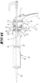
- einen Längsschnitt durch die in
Fig. 1 dargestellte Kartuschenpresse, jedoch mit in eine erste Schaltstellung verlagertem Umschalter 6, - Fig. 3
- vergrößert den Ausschnitt III in
Fig. 2 , - Fig. 4
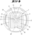
- den Schnitt gemäß der Linie IV-IV in
Fig. 3 durch einen Fesselungsschieber 15, - Fig. 5
- eine Darstellung gemäß
Fig. 3 , jedoch mit einem aus einer Raststellung gebrachten Vorsprung 19', - Fig. 6
- eine Darstellung gemäß
Fig. 4 , jedoch mit teilweise aus einer Formschlusseingriffsstellung herausgezogenem Fesselungsschieber 15, - Fig. 7
- eine Explosionsdarstellung einiger Elemente einer Kartuschenpresse,
- Fig. 8
- vergrößert einen am Ende einer Druckstange 4 angeordneten Druckteller 27, der einen Druckstempel 28 hält,
- Fig. 9
- perspektivisch die in der
Fig. 8 dargestellten Elemente in einer Einzeldarstellung, - Fig. 10
- ein zweites Ausführungsbeispiel, bei dem das Betätigungsgehäuse 1 mit einer anders gestalteten Aufnahmeeinrichtung 10 verbunden ist, in einer zweiten perspektivischen Darstellung,
- Fig. 11
- eine Schnittdarstellung des zweiten Ausführungsbeispiels ähnlich der
Fig. 2 , jedoch mit einem Umschalter 6, der seine zweite Schaltstellung einnimmt, - Fig. 12
- einen Schnitt gemäß der Linie XII - XII in
Fig. 2 , - Fig. 12a
- vergrößert den Ausschnitt XIIa in
Fig. 12 , - Fig. 13
- den Schnitt gemäß der Linie XIII - XIII in
Fig. 2 , und - Fig. 13a
- vergrößert den Ausschnitt XIIIa in
Fig. 13 . - Die in den Zeichnungen dargestellten Kartuschenpressen besitzen ein Betätigungsgehäuse 1, welches aus Kunststoff oder einem anderen Material, wie bspw. Metall, gefertigt ist und an welchem um eine Schwenkachse 35 eine Handhabe 2 in Richtung auf einen Handgriff 3 ebenfalls schwenkbar ein Lösehebel 5 angelenkt sind. Eine Druckstange 4 ist in Richtung ihrer Achserstreckung verschieblich im Betätigungsgehäuse 1 gelagert. Auf dem rückwärtigen Ende der Druckstange 4 sitzen ein Handgriff und eine Anschlagfeder. Auf dem druckseitigen Ende der Druckstange 4 ist ein Druckteller 27 befestigt. Hierzu kann das Ende der Druckstange 4 eine Umfangsnut aufweisen, in der ein Sicherungsring eingesetzt ist. Es ist aber auch vorgesehen, dass ein Gewinde der Druckstange 4 in ein Gewinde des Drucktellers 27 eingreift. Der Rand 27' des Drucktellers 27 greift in eine Bogennut 36 eines Druckstempels 28 ein (siehe
Figuren 8 und 9 ). - Die Schwenkachse 35 steckt in einer Exzenterbuchse 34, die in einer Lagerhöhlung des Gehäuses gelagert ist. Mittels eines an der Exzenterbuchse 34 befestigten Umstellhebels 33 lässt sich die Exzenterbuchse 34 verdrehen, um dadurch den Winkel zu verändern, den die Handhabe 2 gegenüber dem Handgriff 3 einnimmt.
- Die Handhabe 2 ist im Wesentlichen ein zweiarmiger Hebel mit einem langen Hebelarm, der von den Fingern einer Hand eines Benutzers umgriffen werden kann, und einem kurzen Hebelarm, der an einem aus zwei Stahlplatten bestehenden Mitnahmeglied 8 angreift. Wenn der kurze Hebelarm das Mitnahmeglied 8 kraftbeaufschlagt, wird das Mitnahmeglied 8 verkippt. Die Druckstange 4 durchgreift eine Öffnung des Mitnahmeglieds 8, so dass sich das Mitnahmeglied 8 bei einem Verkippen gegenüber der Druckstange 4 verkantet. Eine Verlagerung des Mitnahmeglieds 8 durch das Verschwenken der Handhabe 2 hat somit eine Linearverlagerung der Druckstange 4 in Druckrichtung zur Folge, in welcher sich der Druckteller 27 innerhalb der Aufnahmeeinrichtung 10 in Richtung auf eine Tülle 30 verlagert.
- Wird nach einem Verschwenken die Handhabe 2 wieder losgelassen, so wird die Handhabe 2 von einer Schenkelfeder in die Ausgangsstellung zurückgeschwenkt. Das Mitnahmeglied 8 wird mittels einer Feder 7 in die Ausgangsstellung gebracht.
- Der Lösehebel 5 besitzt ebenfalls einen ersten, längeren Arm, der von einem Finger der Hand eines Benutzers umgriffen werden kann, und einen kurzen Hebelarm, der einen exzentrischen Fortsatz ausbildet, der an einem Rückdrücksperrglied 9 angreift. Beim Rückdrücksperrglied 9 kann es sich um eine Stahlplatte handeln, die eine Öffnung aufweist, durch die die Druckstange 4 hindurchtritt. Nimmt das Rückdrücksperrglied 9 eine Verkipptstellung gegenüber der Druckstange 4 ein, so kann die Druckstange 4 nur in Druckrichtung verlagert werden. Nimmt das Rückdrücksperrglied 9 hingegen keine Verkipptstellung ein, so kann die Druckstange 4 axial in beiden Richtungen gegenüber dem Rückdrücksperrglied 9 verlagert werden.
- Das Betätigungsgehäuse 1 besitzt eine erste Seite, auf der der Lösehebel 5 und die Handhabe 2 sowie der Handgriff 3 angeordnet sind. Dieser ersten Seite liegt eine zweite Seite gegenüber. Zwischen den beiden Seiten erstreckt sich die Druckstange 4 und befindet sich das Rückdrücksperrglied 9. Von der zweiten Seite des Betätigungsgehäuses 1 ragt ein Betätigungsabschnitt eines Umschalters 6 heraus. Der Umschalter 6 kann von einer ersten Schaltstellung, die in der
Fig. 2 dargestellt ist, in eine zweite Schaltstellung gebracht werden, die in derFig. 11 dargestellt ist. In der ersten Schaltstellung nimmt das Rückdrücksperrglied 9 eine Wirkstellung ein. In dieser Stellung kann die Druckstange 4 nur durch Betätigen des Lösehebels 5 entgegen der Druckrichtung verlagert werden. In der Wirkstellung greift ein exzentrisch von einer Schwenkachse des Umschalters 6 abragender Exzenterabschnitt 31 an einem Randabschnitt des Rückdrücksperrglieds 9 an. Das Rückdrücksperrglied 9 wird dadurch auf seiner dem Lösehebel 5 gegenüberliegenden Seite in Achsrichtung gefesselt. Der Exzenterabschnitt 31 drückt den dortigen Rand des Rückdrücksperrgliedes 9 gegen eine Gehäusewand des Betätigungsgehäuses 1. - Eine Feder 22 beaufschlagt das Rückdrücksperrglied 9 derart, dass es eine Verkipptstellung einnimmt, so dass sich die Druckstange 4 in der Öffnung des Rückdrücksperrglieds 9 verkantet. Wird der Lösehebel 5 verschwenkt, so wird das Rückdrücksperrglied 9 gegen die Kraft der Feder 22 aus der Verkipptlage gebracht.
- Das Rückdrücksperrglied 9 wird auch aus der Verkipptlage gebracht, wenn der Umschalter 6 von der in
Fig. 2 dargestellten ersten Schaltstellung in die inFig. 11 dargestellte zweite Schaltstellung gebracht wird. Dann stützt sich das von der Feder 22 beaufschlagte Rückdrücksperrglied 9 derart an einem Abschnitt des Umschalters 6 und am Lösehebel 5 ab, dass die Druckstange 4 frei durch die Öffnung des Rückdrücksperrglieds 9 bewegt werden kann. - Das Rückdrücksperrglied 9 kann somit zwei verschiedene Außerwirkstellungen einnehmen, in denen das Rückdrücksperrglied 9 jeweils sich in etwa quer zur Erstreckungsrichtung der Druckstange 4 erstreckt. In einer ersten Außerwirkstellung wird es von dem mit Exzenterabschnitt 31 bezeichneten Vorsprung des Umschalters 6 und vom kurzen Arm des Lösehebels 5 bei dessen Betätigung gegen die Gehäusewandung gedrückt. In der zweiten Außerwirkstellung befindet sich das Rückdrücksperrglied 9 von der Gehäusewandung 37 beabstandet und wird von einem Abschnitt des Umschalters 6 und vom nicht betätigten Lösehebel 5 in einer Parallellage zur Gehäusewandung 37 gehalten.
- Die Aufnahmeeinrichtung 10 ist drehbar mit dem Betätigungsgehäuse 1 verbunden. Die Drehachse wird von der Druckstange 4 ausgebildet. Die Druckstange 4 durchgreift in der axialen Mitte eine Befestigungsöffnung 13 einer Stirnwand 20 des Betätigungsgehäuses 1. Die Befestigungsöffnung 13 hat einen kreisrunden Grundriss. An die Befestigungsöffnung 13 schließt sich ein Radialschacht 14 des Betätigungsgehäuses 1 an. Der Radialschacht 14 erstreckt sich in Radialrichtung bezogen auf die Druckstange 4 und besitzt eine Mündung, die im Bereich des Betätigungsabschnittes des Lösehebels 5 liegt.
- Die Aufnahmeeinrichtung 10 besitzt einen Befestigungssockel 11, der einer Stirnwand 21 der Aufnahmeeinrichtung 10 entspringt. Der Befestigungssockel 11 besitzt eine Stirnfläche 11', die eine Mulde 23 aufweist, und eine Öffnung 12, durch die die Druckstange 4 hindurchgeführt ist.
- Der Befestigungssockel 11 wird zur Befestigung der Aufnahmeeinrichtung 10 am Betätigungsgehäuse 1 in die Befestigungsöffnung 13 eingesteckt. Hierzu besitzt der Befestigungssockel 11 einen Außendurchmesser, der dem Innendurchmesser der Öffnung 12 entspricht.
- Der Befestigungssockel 11 besitzt eine Umfangsringnut 16. Im eingesteckten Zustand befindet sich die Umfangsringnut 16 im Bereich des Radialschachtes 14. Die Stirnwand 20 kann dabei an der Stirnwand 21 anliegen. Die beiden Stirnwände 20, 21 können aber auch voneinander beabstandet sein. Der Radialschacht besitzt zwei voneinander beabstandete Wände, nämlich die Stirnwand 20 und die dazu parallel verlaufende Wand 38, die eine Öffnung 39 aufweist, in der ein Abschnitt des Befestigungssockels 11 steckt, wobei die Öffnung 39 mit der Öffnung 13 fluchtet.
- In den Radialschacht 14 wird ein aus Stahl gefertigter Fesselungsschieber 15 eingeschoben, der eine U-förmige Aussparung aufweist. Die Ränder der U-förmigen Aussparung bilden eine Fesselungsflanke 17 aus, die in einer Formschlusseingriffsstellung in die Ringnut 16 eingreift, so dass dadurch der Befestigungssockel 11 axial in der Öffnung 12 gefesselt und damit die Aufnahmeeinrichtung 10 axial an das Betätigungsgehäuse 1 gefesselt ist.
- Da der Befestigungssockel 11 drehbar in der Befestigungsöffnung 13 einliegt, kann die Aufnahmeeinrichtung 10 um einen beliebigen Drehwinkel gegenüber dem Betätigungsgehäuse 1 gedreht werden.
- Im Ausführungsbeispiel steckt der Fesselungsschieber 15 derart im Radialschacht 14, dass er nur mit Hilfe eines Werkzeuges, beispielsweise mit der Klinge eines Schraubendrehers aus seiner Formschlusseingriffsstellung entfernt werden kann. Hierzu muss ein Rastvorsprung 19' einer Rastzunge 19 aus einer Hintergriffsstellung gebracht werden. Im Ausführungsbeispiel ragt der Rastvorsprung 19' in eine Rastöffnung 18 des Fesselungsschiebers 15 ein, wobei die Rastöffnung 18 der Fesselungsöffnung 17 gegenüberliegt. Die Rastzunge 15 ist aus der Wand 38 freigeschnitten.
- Die Feder 22, die das Rückdrücksperrglied 9 beaufschlagt, und durch welche die Druckstange 4 hindurchgesteckt ist, stützt sich an der Stirnfläche des Betätigungssockels 11 ab. Sie liegt auf dem Boden der Mulde 23.
- Bei dem in den
Figuren 1 bis 7 dargestellten Ausführungsbeispiel besitzt die Aufnahmeeinrichtung 10 ein Endstück 24, welches formschlüssig, beispielsweise über eine Bajonettverbindung mit einem rohrförmigen Aufnahmekörper 25 verbunden ist. Das Endstück 24 verschließt eine Rohröffnung und bildet die Stirnwand 21 und den von der Stirnwand 21 abragenden Befestigungssockel 11 materialeinheitlich aus und ist hierzu bevorzugt als Kunststoffteil ausgebildet. - Die andere Rohröffnung des Aufnahmekörpers 25 wird von einem Kopfstück 26 verschlossen, welches die Tülle 30 tragen kann.
- Bei dem in den
Figuren 10 und11 dargestellten zweiten Ausführungsbeispiel einer Aufnahmeeinrichtung 10 sitzt das Endstück 24' an einem wannenförmigen Aufnahmekörper 25' zur Aufnahme einer Kartusche. Das kopfseitige Ende des Aufnahmekörpers 25' besitzt einen Einschnitt zum Einsetzen der Tülle 30. - Die
Figuren 12 bis 13a zeigen die Verbindung des Kopfstückes 26 bzw. des Endstücks 24 jeweils mit einem Ende des als Rohr ausgebildeten Aufnahmekörpers 25. Es handelt sich um eine Bajonettverbindung, also eine Steckdrehverbindung. Der Aufnahmekörper 25 wird in einen Hülsenabschnitt des Endstücks 24 bzw. des Kopfstücks 26 eingesteckt. Der Hülsenabschnitt bzw. der Endabschnitt des Aufnahmekörpers 25 besitzt Fesselungselemente, die nach einer Teildrehung des Endstücks 24 bzw. Kopfstücks 26 relativ gegenüber dem Aufnahmekörper 25 in eine axiale Hintereinanderlage treten, so dass sie das Endstück 24 bzw. Kopfstück 26 axial an den Aufnahmekörper 25 fesseln. Um das Endstück 24 bzw. das Kopfstück 26 in der gefesselten Endstellung zu halten, sind Rastmittel vorgesehen, die in der Drehendstellung zur Erzeugung einer Drehhemmung miteinander wirken. Die Rastmittel besitzen insbesondere Rastelemente, die ineinandergreifen. Die Rastelemente können von verzahnten Abschnitten des Kopfstücks 26, des Endstücks 24 und der beiden Enden des Aufnahmekörpers 25 gebildet sein. - Beim Ausführungsbeispiel besitzt die Außenwandung des Aufnahmekörpers 25 radial nach außen weisende Rastwülste 40. In Umfangsrichtung liegen vier Rastwülste nebeneinander. Die Innenwandung des Hülsenabschnitts des Endstücks 24 bzw. Kopfstücks 26 besitzen Gegenrastelemente, die mit den Rastelementen zusammenwirken. Die Gegenrastelemente werden von Rastnuten 41 bzw. 42 gebildet, in die die Rastwülste 40 eintreten. Das Endstück 24 besitzt vier Rastnuten 41. Die Anzahl der Rastwülste 40 entspricht hier der Anzahl der Rastnuten 41.
- Das in der
Fig. 13 bzw.Fig. 13a dargestellte Kopfstück 26 besitzt hingegen eine geringere Anzahl an Rastnuten 42 als das Endstück 24. Im Ausführungsbeispiel sind es zwei Rastnuten 42, in die lediglich zwei der Rastwülste 40 eingreifen. - Die drehhemmende Rastverbindung zwischen Endstück 24 und Aufnahmekörper 25 bzw. Kopfstück 26 und Aufnahmekörper 25 sind so gewählt, dass zum Lösen des Kopfstücks 26 vom Aufnahmekörper 25 ein geringeres Drehmoment erforderlich ist als zum Lösen des Aufnahmekörpers 25 vom Endstück 24. Dies bringt den Vorteil, dass zum Entfernen des Kopfstücks die Kartuschenpresse am Handgriff 3 gehalten werden kann und lediglich das Kopfstück 26 gedreht werden muss. Da die Anzahl der ineinandergreifenden Rastmittel 42, 40 im Bereich des Kopfstücks 26 geringer ist als die Anzahl der ineinandergreifenden Rastmittel 40, 41 im Bereich des Endstücks 24, kann das Kopfstück 26 vom Aufnahmekörper 25 gelöst werden, ohne dass sich die Rastverbindung zwischen Endstück 24 und Aufnahmekörper 25 löst. Um die Rastverbindung zwischen Aufnahmekörper 25 und Endstück 24 zu lösen, muss ein höheres Drehmoment aufgebracht werden.
- Der Aufnahmekörper 25 und/ oder das Endstück 24 und das Kopfstück 26 sind aus einem elastisch verformbaren Werkstoff gefertigt, so dass durch Aufbringen eines Drehmomentes eine elastische Verformung erfolgt, bei der die Rastwülste 40, 41 aus den ihnen zugeordneten Rastnuten 42 heraustreten. Dies erfolgt durch ein Schrägflanken-Entlanggleiten, wobei die Schrägflanken von den Rastwülsten 40, 41 und den Rastnuten 42 ausgebildet sind.
- Die vorstehenden Ausführungen dienen der Erläuterung der von der Anmeldung insgesamt erfassten Erfindungen, die den Stand der Technik zumindest durch die folgenden Merkmalskombinationen jeweils auch eigenständig weiterbilden, wobei zwei, mehrere oder alle dieser Merkmalskombinationen auch kombiniert sein können, nämlich:
- Eine Kartuschenpresse, die dadurch gekennzeichnet ist, dass das Formschlussmittel ein in einen Radialschacht 14 eingeschobener Fesselungsschieber 15 ist, der mit einer Fesselungsflanke 17 in eine Ringnut 16 des Befestigungssockels 11 eingreift.
- Eine Kartuschenpresse, die dadurch gekennzeichnet ist, dass der Befestigungssockel 11 an der Aufnahmeeinrichtung 10 sitzt und die Befestigungsöffnung 13 sowie der Radialschacht 14 vom Betätigungsgehäuse 1 ausgebildet sind.
- Eine Kartuschenpresse, die gekennzeichnet ist durch einen in den Radialschacht 14 ragenden Rastvorsprung 19' einer Rastzunge 19, der durch Hintergreifen des Fesselungsschiebers 15 den Fesselungsschieber 15 in seiner Fesselungsstellung hält.
- Eine Kartuschenpresse, die dadurch gekennzeichnet ist, dass der Fesselungsschieber 15 aus Stahl gefertigt ist und/oder eine Rastöffnung 18 aufweist, in die der Rastvorsprung 19' eingreift, der von einer Wand des Radialschachtes 14 abragt.
- Eine Kartuschenpresse, die dadurch gekennzeichnet ist, dass der Fesselungsschieber 15 von Hand unlösbar in der Fesselungsstellung gefesselt ist.
- Eine Kartuschenpresse, die dadurch gekennzeichnet ist, dass der Befestigungssockel 11 materialeinheitlich einem insbesondere aus Kunststoff gefertigten Endstück 24, 24' der Aufnahmeeinrichtung 10 entspringt.
- Eine Kartuschenpresse, die dadurch gekennzeichnet ist, dass der Befestigungssockel 11 in Axialrichtung von einer dem Betätigungsgehäuse 1 zugeordneten Feder 22 beaufschlagt wird, wobei die Feder 22 insbesondere eine Druckfeder ist, die ein Rückdrücksperrglied 9 beaufschlagt.
- Eine Kartuschenpresse, die dadurch gekennzeichnet ist, dass der Umschalter 6 auf einer zweiten Seite des Betätigungsgehäuses 1 angeordnet ist, die bezogen auf die Druckstange 4 der ersten Seite gegenüberliegt, und einen Abschnitt, insbesondere einen Exzenterabschnitt 31 aufweist, der in der Wirkstellung am Rückdrücksperrglied 9 anliegt.
- Eine Kartuschenpresse, die dadurch gekennzeichnet ist, dass der Umschalter 6 ein Schwenkhebel ist.
- Eine Kartuschenpresse, die dadurch gekennzeichnet ist, dass ein Winkel der Handhabe 2 zu einem Handgriff 3 mittels einer Griffweitenverstelleinrichtung 33, 35 verstellbar ist.
- Eine Kartuschenpresse, die dadurch gekennzeichnet ist, dass das erste Drehmoment durch erste ineinandergreifende Rastmittel 40, 41 und das zweite Drehmoment durch zweite ineinandergreifende Rastmittel 40, 42 definiert ist und die beiden Rastmittel 40, 41, 42 derart ausgebildet sind, dass das erste Drehmoment kleiner ist als das zweite Drehmoment.
- Eine Kartuschenpresse, die dadurch gekennzeichnet ist, dass die Rastmittel Rastwülste 40 aufweisen, die in Rastnuten 41, 42 eingreifen.
- Eine Kartuschenpresse, die dadurch gekennzeichnet ist, dass die Anzahl der in Rastnuten 42 eingreifenden Rastwülste 40 des Kopfstücks 26 kleiner ist als die Anzahl der in Rastnuten 41 eingreifenden Rastwülste 40 des Endstücks 24.
- Eine Kartuschenpresse, die dadurch gekennzeichnet ist, dass die Rastnuten 41, 42 und die Rastwülste 40 von in Umfangsrichtung an einem Hülsenabschnitt des Kopfstücks 26 und des Endstücks 24 sowie den beiden Enden des Aufnahmekörpers 25 angeordneten Zahnstrukturen gebildet sind.
- Alle offenbarten Merkmale sind (für sich, aber auch in Kombination untereinander) erfindungswesentlich. In die Offenbarung der Anmeldung wird hiermit auch der Offenbarungsinhalt der zugehörigen/beigefügten Prioritätsunterlagen (Abschrift der Voranmeldung) vollinhaltlich mit einbezogen, auch zu dem Zweck, Merkmale dieser Unterlagen in Ansprüche vorliegender Anmeldung mit aufzunehmen. Die Unteransprüche charakterisieren mit ihren Merkmalen eigenständige erfinderische Weiterbildungen des Standes der Technik, insbesondere um auf Basis dieser Ansprüche Teilanmeldungen vorzunehmen.
-
1 Betätigungsgehäuse 25' Aufnahmekörper 2 Handhabe 26 Kopfstück 3 Handgriff 27 Druckteller 4 Druckstange 27' Rand 5 Lösehebel 28 Druckstempel 6 Umschalter 29 pastöse Masse 7 Feder 30 Tülle 8 Mitnahmeglied 31 Exzenterabschnitt 9 Rückdrücksperrglied 32 Schwenkachse 10 Aufnahmeeinrichtung 33 Umstellhebel 11 Befestigungssockel 34 Exzenterbuchse 11' Stirnfläche 35 Schwenkachse 12 Öffnung 36 Bogennut 13 Befestigungsöffnung 37 Gehäusewandung 14 Radialschacht 38 Wand 15 Fesselungsschieber 39 Öffnung 16 Ringnut 40 Rastwulst 17 Fesselungsflanke 41 Rastnut 18 Rastöffnung 42 Rastnut 19 Rastzunge 19' Vorsprung 20 Stirnwand 21 Stirnwand 22 Feder 23 Mulde 24 Endstück 24' Endstück 25 Aufnahmekörper
Claims (14)
- Kartuschenpresse mit einem Betätigungsgehäuse (1), das eine Handhabe (2) aufweist, deren Bewegung relativ gegenüber dem Betätigungsgehäuse (1) in einer Betätigungsrichtung eine Verlagerung einer im Betätigungsgehäuse (1) verschieblich gelagerten Druckstange (4) in einer Druckrichtung zur Folge hat, und mit einer Aufnahmeeinrichtung (10) zur Aufnahme einer durch die Verlagerung der Druckstange (4) aus einem Schlauch oder einer Kartusche ausdrückbaren pastösen Masse (29), wobei die Aufnahmeeinrichtung (10) drehbar am Betätigungsgehäuse (1) befestigt ist, wozu ein eine Öffnung (12) zum Durchtritt der Druckstange (4) aufweisender Befestigungssockel (11) in eine Befestigungsöffnung (13) hineinragt und dort mit einem Formschlussbefestigungsmittel axial bezogen auf die Druckstange (4) gefesselt ist, dadurch gekennzeichnet, dass das Formschlussmittel ein in einen Radialschacht (14) eingeschobener Fesselungsschieber (15) ist, der mit einer Fesselungsflanke (17) in eine Ringnut (16) des Befestigungssockels (11) eingreift.
- Kartuschenpresse nach Anspruch 1, dadurch gekennzeichnet, dass der Befestigungssockel (11) an der Aufnahmeeinrichtung (10) sitzt und die Befestigungsöffnung (13) sowie der Radialschacht (14) vom Betätigungsgehäuse (1) ausgebildet sind.
- Kartuschenpresse nach einem der vorhergehenden Ansprüche, gekennzeichnet durch einen in den Radialschacht (14) ragenden Rastvorsprung (19') einer Rastzunge (19), der durch Hintergreifen des Fesselungsschiebers (15) den Fesselungsschieber (15) in seiner Fesselungsstellung hält.
- Kartuschenpresse nach einem der vorhergehenden Ansprüche, dadurch gekennzeichnet, dass der Fesselungsschieber (15) aus Stahl gefertigt ist und/oder eine Rastöffnung (18) aufweist, in die der Rastvorsprung (19') eingreift, der von einer Wand des Radialschachtes (14) abragt.
- Kartuschenpresse nach einem der vorhergehenden Ansprüche, dadurch gekennzeichnet, dass der Fesselungsschieber (15) von Hand unlösbar in der Fesselungsstellung gefesselt ist.
- Kartuschenpresse nach einem der vorhergehenden Ansprüche, dadurch gekennzeichnet, dass der Befestigungssockel (11) materialeinheitlich einem insbesondere aus Kunststoff gefertigten Endstück (24, 24') der Aufnahmeeinrichtung (10) entspringt.
- Kartuschenpresse nach einem der vorhergehenden Ansprüche, dadurch gekennzeichnet, dass der Befestigungssockel (11) in Axialrichtung von einer dem Betätigungsgehäuse (1) zugeordneten Feder (22) beaufschlagt wird, wobei die Feder (22) insbesondere eine Druckfeder ist, die ein Rückdrücksperrglied (9) beaufschlagt.
- Kartuschenpresse nach einem der vorhergehenden Ansprüche 1-6 mit einem auf einer ersten Seite der Druckstange (4) am Betätigungsgehäuse (1) angeordneten Lösehebel (5) zum Zusammenwirken mit einem Rückdrücksperrglied (9), und mit einem Umschalter (6), der von einer ersten Schaltstellung, in der das Rückdrücksperrglied (9) eine Wirkstellung zur Druckstange (4) einnimmt, in eine zweite Schaltstellung bringbar ist, in der das Rückdrücksperrglied (9) eine Außerwirkstellung zur Druckstange (4) einnimmt, dadurch gekennzeichnet, dass der Umschalter (6) auf einer zweiten Seite des Betätigungsgehäuses (1) angeordnet ist, die bezogen auf die Druckstange (4) der ersten Seite gegenüberliegt, und einen Abschnitt, insbesondere einen Exzenterabschnitt (31) aufweist, der in der Wirkstellung am Rückdrücksperrglied (9) anliegt.
- Kartuschenpresse nach Anspruch 8, dadurch gekennzeichnet, dass der Umschalter (6) ein Schwenkhebel ist.
- Kartuschenpresse nach einem der vorhergehenden Ansprüche, dadurch gekennzeichnet, dass ein Winkel der Handhabe (2) zu einem Handgriff (3) mittels einer Griffweitenverstelleinrichtung (33, 35) verstellbar ist.
- Kartuschenpresse nach einem der vorhergehenden Ansprüche, bei der ein erstes Ende eines Aufnahmekörpers (25) zur Aufnahme der pastösen Masse durch Aufbringen eines ersten Drehmomentes lösbar an einem Endstück (24) befestigt ist, durch welches Endstück (24) eine Druckstange (4) hindurchgreift, und bei der ein dem ersten Ende gegenüberliegendes zweites Ende des Aufnahmekörpers (25) durch Aufbringen eines zweiten Drehmomentes lösbar an einem Kopfstück (26) befestigt ist, dem eine Öffnung zum Auspressen der pastösen Masse räumlich zugeordnet ist, dadurch gekennzeichnet, dass das erste Drehmoment durch erste ineinandergreifende Rastmittel (40, 41) und das zweite Drehmoment durch zweite ineinandergreifende Rastmittel (40, 42) definiert ist und die beiden Rastmittel (40, 41, 42) derart ausgebildet sind, dass das erste Drehmoment kleiner ist als das zweite Drehmoment.
- Kartuschenpresse nach Anspruch 11, dadurch gekennzeichnet, dass die Rastmittel Rastwülste (40) aufweisen, die in Rastnuten (41, 42) eingreifen.
- Kartuschenpresse nach einem der Ansprüche 11 oder 12, dadurch gekennzeichnet, dass die Anzahl der in Rastnuten (42) eingreifenden Rastwülste (40) des Kopfstücks (26) kleiner ist als die Anzahl der in Rastnuten (41) eingreifenden Rastwülste (40) des Endstücks (24).
- Kartuschenpresse nach einem der Ansprüche 11 bis 13, dadurch gekennzeichnet, dass die Rastnuten (41, 42) und die Rastwülste (40) von in Umfangsrichtung an einem Hülsenabschnitt des Kopfstücks (26) und des Endstücks (24) sowie den beiden Enden des Aufnahmekörpers (25) angeordneten Zahnstrukturen gebildet sind.
Applications Claiming Priority (2)
| Application Number | Priority Date | Filing Date | Title |
|---|---|---|---|
| DE102017100627.3A DE102017100627A1 (de) | 2017-01-13 | 2017-01-13 | Kartuschenpresse |
| PCT/EP2018/050625 WO2018130599A2 (de) | 2017-01-13 | 2018-01-11 | Kartuschenpresse |
Publications (2)
| Publication Number | Publication Date |
|---|---|
| EP3568239A2 EP3568239A2 (de) | 2019-11-20 |
| EP3568239B1 true EP3568239B1 (de) | 2024-11-06 |
Family
ID=61007685
Family Applications (1)
| Application Number | Title | Priority Date | Filing Date |
|---|---|---|---|
| EP18700876.8A Active EP3568239B1 (de) | 2017-01-13 | 2018-01-11 | Kartuschenpresse |
Country Status (4)
| Country | Link |
|---|---|
| EP (1) | EP3568239B1 (de) |
| CN (1) | CN110191764B (de) |
| DE (1) | DE102017100627A1 (de) |
| WO (1) | WO2018130599A2 (de) |
Families Citing this family (5)
| Publication number | Priority date | Publication date | Assignee | Title |
|---|---|---|---|---|
| DE202017107724U1 (de) | 2017-12-19 | 2019-03-21 | Wolfcraft Gmbh | Kolben für eine Kartuschen-Ausdrückvorrichtung |
| DE102019108139B4 (de) * | 2019-03-28 | 2022-07-07 | Siang Syuan Fu Enterprise Co., Ltd. | Kartuschenpistole und deren Anwendung |
| GB2582641B (en) * | 2019-03-29 | 2023-05-17 | Siang Syuan Fu Entpr Co Ltd | Caulking gun and method for using the same |
| CN111503083B (zh) * | 2020-04-10 | 2021-12-17 | 广东博智林机器人有限公司 | 一种活塞执行机构及填缝机器人 |
| CN114054313A (zh) * | 2020-08-04 | 2022-02-18 | 北京长征天民高科技有限公司 | 一种手动涂胶工具 |
Citations (1)
| Publication number | Priority date | Publication date | Assignee | Title |
|---|---|---|---|---|
| US20080041886A2 (en) * | 2003-07-31 | 2008-02-21 | Danny Rumrill | Caulking gun |
Family Cites Families (21)
| Publication number | Priority date | Publication date | Assignee | Title |
|---|---|---|---|---|
| US5431A (en) | 1848-02-01 | Faucet | ||
| US654A (en) | 1838-03-23 | Improvement in shot-charges for measuring shot in charging guns | ||
| DE1927348A1 (de) * | 1969-05-29 | 1970-12-23 | Heitz Walter Helmut | Behaelter bzw. Spender fuer pastenfoermige Stoffe |
| US3997085A (en) * | 1976-01-15 | 1976-12-14 | Berkley James Lindquist | Caulking gun |
| CA1080172A (en) * | 1977-05-11 | 1980-06-24 | Yasuo Ichinose | Gun for extruding sealant |
| DE8229452U1 (de) * | 1982-10-21 | 1983-05-05 | Haushaltsprodukte Vertriebsgesellschaft mbH, 5430 Montabaur | Vorrichtung zum herstellen von formstuecken aus teig |
| US5431654A (en) | 1991-09-30 | 1995-07-11 | Stryker Corporation | Bone cement injector |
| US5615807A (en) * | 1994-10-12 | 1997-04-01 | Peng; Yuenan | Convertible dripless caulking gun for variant viscosity media |
| US5887765A (en) | 1996-08-16 | 1999-03-30 | Dripless, Inc. | Caulk gun |
| US5871299A (en) * | 1997-10-16 | 1999-02-16 | Lai; Ming-Tang | Quick-release mechanism for a compressing device |
| WO2005097354A1 (de) * | 2004-04-08 | 2005-10-20 | Ray Technology Group B.V. | Kartuschenpistole mit kartuschenhalterung |
| US7011238B1 (en) * | 2005-09-14 | 2006-03-14 | Kent Bridge Enterprise Co., Ltd. | Adjustable caulk dispensing gun |
| EP2032467B1 (de) * | 2006-06-13 | 2010-08-18 | Nordson Corporation | Flüssigkeitsausgabespritze |
| GB0616793D0 (en) * | 2006-08-24 | 2006-10-04 | Cox Ltd | Dispensing apparatus |
| US8011538B2 (en) * | 2007-02-21 | 2011-09-06 | Meritool, Llc | Dispensing tool |
| US20100237105A1 (en) * | 2009-03-17 | 2010-09-23 | John Zagone | Viscous Material Dispenser |
| GB2498318B (en) * | 2010-11-15 | 2014-01-15 | Milwaukee Electric Tool Corp | Powered dispensing tool |
| EP2878383B1 (de) * | 2013-11-29 | 2017-11-01 | Techtronic Power Tools Technology Limited | Abdichtungspistole und Kupplungsvorrichtung für eine Abdichtungspistole |
| DE102014105935A1 (de) | 2014-04-28 | 2015-10-29 | Wolfcraft Gmbh | Werkzeug mit Griffweitenverstellung |
| EP2954959A1 (de) * | 2014-06-12 | 2015-12-16 | Altachem N.V. | Kartuschenpistole |
| DE102014116514B4 (de) | 2014-11-12 | 2025-03-20 | Wolfcraft Gmbh | Spannvorrichtung, insbesondere in Form einer Kartuschen-Ausdrückvorrichtung |
-
2017
- 2017-01-13 DE DE102017100627.3A patent/DE102017100627A1/de active Pending
-
2018
- 2018-01-11 CN CN201880006982.1A patent/CN110191764B/zh active Active
- 2018-01-11 EP EP18700876.8A patent/EP3568239B1/de active Active
- 2018-01-11 WO PCT/EP2018/050625 patent/WO2018130599A2/de not_active Ceased
Patent Citations (1)
| Publication number | Priority date | Publication date | Assignee | Title |
|---|---|---|---|---|
| US20080041886A2 (en) * | 2003-07-31 | 2008-02-21 | Danny Rumrill | Caulking gun |
Also Published As
| Publication number | Publication date |
|---|---|
| WO2018130599A2 (de) | 2018-07-19 |
| EP3568239A2 (de) | 2019-11-20 |
| DE102017100627A1 (de) | 2018-07-19 |
| CN110191764B (zh) | 2021-08-10 |
| CN110191764A (zh) | 2019-08-30 |
| WO2018130599A3 (de) | 2018-11-29 |
Similar Documents
| Publication | Publication Date | Title |
|---|---|---|
| EP2135714B1 (de) | Schraubwerkzeug mit Freilaufgetriebe | |
| DE102007049032B4 (de) | Zange | |
| AT502487B1 (de) | Dämpferanordnung | |
| DE3342497C2 (de) | ||
| EP3568239A2 (de) | Kartuschenpresse | |
| EP3256089B1 (de) | Spannklaue zur anbringung an einer gleitschiene eines operationstisches | |
| EP3030209A1 (de) | Spannklaue zur anbringung an einer gleitschiene eines operationstisches | |
| DE202019101933U1 (de) | Auspresspistole | |
| EP2142340A1 (de) | Hand-zangenwerkzeug | |
| WO2017129402A1 (de) | Schraubwerkzeug mit richtungsumschaltbarem freilaufgesperre | |
| EP1050378A2 (de) | "Wasserpumpenzange mit Einhandbedienung" | |
| WO2016197163A1 (de) | Ausstossvorrichtung für ein bewegbares möbelteil | |
| DE102014100329B4 (de) | In Klemmmaß einstellbarer Knarrenschlüssel | |
| DE29914764U1 (de) | Zange | |
| EP1853136B1 (de) | Verstellbares sitzmöbel | |
| EP3210724B1 (de) | Werkzeug mit griffweitenverstellung | |
| DE202010006494U1 (de) | Handbetätigte Spannwerkzeuge | |
| DE4424493C2 (de) | Zangenartiges Werkzeug zum formschlüssigen Verbinden von Blechteilen | |
| DE102006056004B4 (de) | Gelenkbeschlag für Kraftfahrzeugsitze mit mindestens zwei Sperrarmen | |
| DE10127425A1 (de) | Offenhaltevorrichtung für einen beweglichen Verschluss | |
| DE102006027313A1 (de) | Einrichtung zur mechanischen Richtungsumkehr eines drehbeweglichen Steuerbauteils | |
| EP3733336A1 (de) | Klemmhalter | |
| DE102006011487B4 (de) | Spanner mit Knarrenverriegelung | |
| EP3701836B1 (de) | Vorrichtung zur verbindung eines frontelements mit einem seitenteil eines bewegbaren möbelteils | |
| DE102010037787B4 (de) | Ratschenschlüssel |
Legal Events
| Date | Code | Title | Description |
|---|---|---|---|
| STAA | Information on the status of an ep patent application or granted ep patent |
Free format text: STATUS: UNKNOWN |
|
| STAA | Information on the status of an ep patent application or granted ep patent |
Free format text: STATUS: THE INTERNATIONAL PUBLICATION HAS BEEN MADE |
|
| PUAI | Public reference made under article 153(3) epc to a published international application that has entered the european phase |
Free format text: ORIGINAL CODE: 0009012 |
|
| STAA | Information on the status of an ep patent application or granted ep patent |
Free format text: STATUS: REQUEST FOR EXAMINATION WAS MADE |
|
| 17P | Request for examination filed |
Effective date: 20190806 |
|
| AK | Designated contracting states |
Kind code of ref document: A2 Designated state(s): AL AT BE BG CH CY CZ DE DK EE ES FI FR GB GR HR HU IE IS IT LI LT LU LV MC MK MT NL NO PL PT RO RS SE SI SK SM TR |
|
| STAA | Information on the status of an ep patent application or granted ep patent |
Free format text: STATUS: EXAMINATION IS IN PROGRESS |
|
| 17Q | First examination report despatched |
Effective date: 20230123 |
|
| GRAP | Despatch of communication of intention to grant a patent |
Free format text: ORIGINAL CODE: EPIDOSNIGR1 |
|
| STAA | Information on the status of an ep patent application or granted ep patent |
Free format text: STATUS: GRANT OF PATENT IS INTENDED |
|
| INTG | Intention to grant announced |
Effective date: 20240605 |
|
| GRAS | Grant fee paid |
Free format text: ORIGINAL CODE: EPIDOSNIGR3 |
|
| GRAA | (expected) grant |
Free format text: ORIGINAL CODE: 0009210 |
|
| STAA | Information on the status of an ep patent application or granted ep patent |
Free format text: STATUS: THE PATENT HAS BEEN GRANTED |
|
| AK | Designated contracting states |
Kind code of ref document: B1 Designated state(s): AL AT BE BG CH CY CZ DE DK EE ES FI FR GB GR HR HU IE IS IT LI LT LU LV MC MK MT NL NO PL PT RO RS SE SI SK SM TR |
|
| REG | Reference to a national code |
Ref country code: GB Ref legal event code: FG4D Free format text: NOT ENGLISH |
|
| REG | Reference to a national code |
Ref country code: CH Ref legal event code: EP |
|
| REG | Reference to a national code |
Ref country code: DE Ref legal event code: R096 Ref document number: 502018015295 Country of ref document: DE |
|
| REG | Reference to a national code |
Ref country code: IE Ref legal event code: FG4D Free format text: LANGUAGE OF EP DOCUMENT: GERMAN |
|
| REG | Reference to a national code |
Ref country code: LT Ref legal event code: MG9D |
|
| REG | Reference to a national code |
Ref country code: NL Ref legal event code: MP Effective date: 20241106 |
|
| PG25 | Lapsed in a contracting state [announced via postgrant information from national office to epo] |
Ref country code: HR Free format text: LAPSE BECAUSE OF FAILURE TO SUBMIT A TRANSLATION OF THE DESCRIPTION OR TO PAY THE FEE WITHIN THE PRESCRIBED TIME-LIMIT Effective date: 20241106 Ref country code: PT Free format text: LAPSE BECAUSE OF FAILURE TO SUBMIT A TRANSLATION OF THE DESCRIPTION OR TO PAY THE FEE WITHIN THE PRESCRIBED TIME-LIMIT Effective date: 20250306 Ref country code: IS Free format text: LAPSE BECAUSE OF FAILURE TO SUBMIT A TRANSLATION OF THE DESCRIPTION OR TO PAY THE FEE WITHIN THE PRESCRIBED TIME-LIMIT Effective date: 20250306 |
|
| PG25 | Lapsed in a contracting state [announced via postgrant information from national office to epo] |
Ref country code: FI Free format text: LAPSE BECAUSE OF FAILURE TO SUBMIT A TRANSLATION OF THE DESCRIPTION OR TO PAY THE FEE WITHIN THE PRESCRIBED TIME-LIMIT Effective date: 20241106 Ref country code: NL Free format text: LAPSE BECAUSE OF FAILURE TO SUBMIT A TRANSLATION OF THE DESCRIPTION OR TO PAY THE FEE WITHIN THE PRESCRIBED TIME-LIMIT Effective date: 20241106 |
|
| PG25 | Lapsed in a contracting state [announced via postgrant information from national office to epo] |
Ref country code: BG Free format text: LAPSE BECAUSE OF FAILURE TO SUBMIT A TRANSLATION OF THE DESCRIPTION OR TO PAY THE FEE WITHIN THE PRESCRIBED TIME-LIMIT Effective date: 20241106 |
|
| PG25 | Lapsed in a contracting state [announced via postgrant information from national office to epo] |
Ref country code: ES Free format text: LAPSE BECAUSE OF FAILURE TO SUBMIT A TRANSLATION OF THE DESCRIPTION OR TO PAY THE FEE WITHIN THE PRESCRIBED TIME-LIMIT Effective date: 20241106 |
|
| PG25 | Lapsed in a contracting state [announced via postgrant information from national office to epo] |
Ref country code: NO Free format text: LAPSE BECAUSE OF FAILURE TO SUBMIT A TRANSLATION OF THE DESCRIPTION OR TO PAY THE FEE WITHIN THE PRESCRIBED TIME-LIMIT Effective date: 20250206 |
|
| PG25 | Lapsed in a contracting state [announced via postgrant information from national office to epo] |
Ref country code: GR Free format text: LAPSE BECAUSE OF FAILURE TO SUBMIT A TRANSLATION OF THE DESCRIPTION OR TO PAY THE FEE WITHIN THE PRESCRIBED TIME-LIMIT Effective date: 20250207 Ref country code: LV Free format text: LAPSE BECAUSE OF FAILURE TO SUBMIT A TRANSLATION OF THE DESCRIPTION OR TO PAY THE FEE WITHIN THE PRESCRIBED TIME-LIMIT Effective date: 20241106 |
|
| PG25 | Lapsed in a contracting state [announced via postgrant information from national office to epo] |
Ref country code: PL Free format text: LAPSE BECAUSE OF FAILURE TO SUBMIT A TRANSLATION OF THE DESCRIPTION OR TO PAY THE FEE WITHIN THE PRESCRIBED TIME-LIMIT Effective date: 20241106 |
|
| PG25 | Lapsed in a contracting state [announced via postgrant information from national office to epo] |
Ref country code: RS Free format text: LAPSE BECAUSE OF FAILURE TO SUBMIT A TRANSLATION OF THE DESCRIPTION OR TO PAY THE FEE WITHIN THE PRESCRIBED TIME-LIMIT Effective date: 20250206 |
|
| PG25 | Lapsed in a contracting state [announced via postgrant information from national office to epo] |
Ref country code: SM Free format text: LAPSE BECAUSE OF FAILURE TO SUBMIT A TRANSLATION OF THE DESCRIPTION OR TO PAY THE FEE WITHIN THE PRESCRIBED TIME-LIMIT Effective date: 20241106 |
|
| PG25 | Lapsed in a contracting state [announced via postgrant information from national office to epo] |
Ref country code: DK Free format text: LAPSE BECAUSE OF FAILURE TO SUBMIT A TRANSLATION OF THE DESCRIPTION OR TO PAY THE FEE WITHIN THE PRESCRIBED TIME-LIMIT Effective date: 20241106 |
|
| PG25 | Lapsed in a contracting state [announced via postgrant information from national office to epo] |
Ref country code: EE Free format text: LAPSE BECAUSE OF FAILURE TO SUBMIT A TRANSLATION OF THE DESCRIPTION OR TO PAY THE FEE WITHIN THE PRESCRIBED TIME-LIMIT Effective date: 20241106 |
|
| PG25 | Lapsed in a contracting state [announced via postgrant information from national office to epo] |
Ref country code: RO Free format text: LAPSE BECAUSE OF FAILURE TO SUBMIT A TRANSLATION OF THE DESCRIPTION OR TO PAY THE FEE WITHIN THE PRESCRIBED TIME-LIMIT Effective date: 20241106 |
|
| PG25 | Lapsed in a contracting state [announced via postgrant information from national office to epo] |
Ref country code: SK Free format text: LAPSE BECAUSE OF FAILURE TO SUBMIT A TRANSLATION OF THE DESCRIPTION OR TO PAY THE FEE WITHIN THE PRESCRIBED TIME-LIMIT Effective date: 20241106 |
|
| PG25 | Lapsed in a contracting state [announced via postgrant information from national office to epo] |
Ref country code: CZ Free format text: LAPSE BECAUSE OF FAILURE TO SUBMIT A TRANSLATION OF THE DESCRIPTION OR TO PAY THE FEE WITHIN THE PRESCRIBED TIME-LIMIT Effective date: 20241106 |
|
| PG25 | Lapsed in a contracting state [announced via postgrant information from national office to epo] |
Ref country code: IT Free format text: LAPSE BECAUSE OF FAILURE TO SUBMIT A TRANSLATION OF THE DESCRIPTION OR TO PAY THE FEE WITHIN THE PRESCRIBED TIME-LIMIT Effective date: 20241106 |
|
| REG | Reference to a national code |
Ref country code: DE Ref legal event code: R097 Ref document number: 502018015295 Country of ref document: DE |
|
| REG | Reference to a national code |
Ref country code: CH Ref legal event code: PL |
|
| PG25 | Lapsed in a contracting state [announced via postgrant information from national office to epo] |
Ref country code: SE Free format text: LAPSE BECAUSE OF FAILURE TO SUBMIT A TRANSLATION OF THE DESCRIPTION OR TO PAY THE FEE WITHIN THE PRESCRIBED TIME-LIMIT Effective date: 20241106 |
|
| PLBE | No opposition filed within time limit |
Free format text: ORIGINAL CODE: 0009261 |
|
| STAA | Information on the status of an ep patent application or granted ep patent |
Free format text: STATUS: NO OPPOSITION FILED WITHIN TIME LIMIT |
|
| PG25 | Lapsed in a contracting state [announced via postgrant information from national office to epo] |
Ref country code: MC Free format text: LAPSE BECAUSE OF FAILURE TO SUBMIT A TRANSLATION OF THE DESCRIPTION OR TO PAY THE FEE WITHIN THE PRESCRIBED TIME-LIMIT Effective date: 20241106 Ref country code: LU Free format text: LAPSE BECAUSE OF NON-PAYMENT OF DUE FEES Effective date: 20250111 |
|
| 26N | No opposition filed |
Effective date: 20250807 |
|
| PG25 | Lapsed in a contracting state [announced via postgrant information from national office to epo] |
Ref country code: BE Free format text: LAPSE BECAUSE OF NON-PAYMENT OF DUE FEES Effective date: 20250131 |
|
| PG25 | Lapsed in a contracting state [announced via postgrant information from national office to epo] |
Ref country code: CH Free format text: LAPSE BECAUSE OF NON-PAYMENT OF DUE FEES Effective date: 20250131 |
|
| REG | Reference to a national code |
Ref country code: BE Ref legal event code: MM Effective date: 20250131 |
|
| GBPC | Gb: european patent ceased through non-payment of renewal fee |
Effective date: 20250206 |
|
| PG25 | Lapsed in a contracting state [announced via postgrant information from national office to epo] |
Ref country code: GB Free format text: LAPSE BECAUSE OF NON-PAYMENT OF DUE FEES Effective date: 20250206 |
|
| PG25 | Lapsed in a contracting state [announced via postgrant information from national office to epo] |
Ref country code: IE Free format text: LAPSE BECAUSE OF NON-PAYMENT OF DUE FEES Effective date: 20250111 |
|
| REG | Reference to a national code |
Ref country code: AT Ref legal event code: MM01 Ref document number: 1738795 Country of ref document: AT Kind code of ref document: T Effective date: 20250111 |
|
| PGFP | Annual fee paid to national office [announced via postgrant information from national office to epo] |
Ref country code: DE Payment date: 20251219 Year of fee payment: 9 |
|
| PG25 | Lapsed in a contracting state [announced via postgrant information from national office to epo] |
Ref country code: AT Free format text: LAPSE BECAUSE OF NON-PAYMENT OF DUE FEES Effective date: 20250111 |
|
| PGFP | Annual fee paid to national office [announced via postgrant information from national office to epo] |
Ref country code: FR Payment date: 20260120 Year of fee payment: 9 |