EP3566973A1 - Verpackungselement zum verpacken eines haushaltsgeräts - Google Patents
Verpackungselement zum verpacken eines haushaltsgeräts Download PDFInfo
- Publication number
- EP3566973A1 EP3566973A1 EP19170217.4A EP19170217A EP3566973A1 EP 3566973 A1 EP3566973 A1 EP 3566973A1 EP 19170217 A EP19170217 A EP 19170217A EP 3566973 A1 EP3566973 A1 EP 3566973A1
- Authority
- EP
- European Patent Office
- Prior art keywords
- packaging element
- base
- packaging
- receiving opening
- folded state
- Prior art date
- Legal status (The legal status is an assumption and is not a legal conclusion. Google has not performed a legal analysis and makes no representation as to the accuracy of the status listed.)
- Granted
Links
Images



Classifications
-
- B—PERFORMING OPERATIONS; TRANSPORTING
- B65—CONVEYING; PACKING; STORING; HANDLING THIN OR FILAMENTARY MATERIAL
- B65D—CONTAINERS FOR STORAGE OR TRANSPORT OF ARTICLES OR MATERIALS, e.g. BAGS, BARRELS, BOTTLES, BOXES, CANS, CARTONS, CRATES, DRUMS, JARS, TANKS, HOPPERS, FORWARDING CONTAINERS; ACCESSORIES, CLOSURES, OR FITTINGS THEREFOR; PACKAGING ELEMENTS; PACKAGES
- B65D81/00—Containers, packaging elements, or packages, for contents presenting particular transport or storage problems, or adapted to be used for non-packaging purposes after removal of contents
- B65D81/02—Containers, packaging elements, or packages, for contents presenting particular transport or storage problems, or adapted to be used for non-packaging purposes after removal of contents specially adapted to protect contents from mechanical damage
- B65D81/05—Containers, packaging elements, or packages, for contents presenting particular transport or storage problems, or adapted to be used for non-packaging purposes after removal of contents specially adapted to protect contents from mechanical damage maintaining contents at spaced relation from package walls, or from other contents
- B65D81/053—Corner, edge or end protectors
- B65D81/055—Protectors contacting three surfaces of the packaged article, e.g. three-sided edge protectors
- B65D81/056—Protectors contacting three surfaces of the packaged article, e.g. three-sided edge protectors the surfaces being generally perpendicular to each other, e.g. three-sided corner protectors
-
- B—PERFORMING OPERATIONS; TRANSPORTING
- B65—CONVEYING; PACKING; STORING; HANDLING THIN OR FILAMENTARY MATERIAL
- B65D—CONTAINERS FOR STORAGE OR TRANSPORT OF ARTICLES OR MATERIALS, e.g. BAGS, BARRELS, BOTTLES, BOXES, CANS, CARTONS, CRATES, DRUMS, JARS, TANKS, HOPPERS, FORWARDING CONTAINERS; ACCESSORIES, CLOSURES, OR FITTINGS THEREFOR; PACKAGING ELEMENTS; PACKAGES
- B65D5/00—Rigid or semi-rigid containers of polygonal cross-section, e.g. boxes, cartons or trays, formed by folding or erecting one or more blanks made of paper
- B65D5/20—Rigid or semi-rigid containers of polygonal cross-section, e.g. boxes, cartons or trays, formed by folding or erecting one or more blanks made of paper by folding-up portions connected to a central panel from all sides to form a container body, e.g. of tray-like form
- B65D5/30—Rigid or semi-rigid containers of polygonal cross-section, e.g. boxes, cartons or trays, formed by folding or erecting one or more blanks made of paper by folding-up portions connected to a central panel from all sides to form a container body, e.g. of tray-like form with tongue-and-slot or like connections between sides and extensions of other sides
- B65D5/301—Rigid or semi-rigid containers of polygonal cross-section, e.g. boxes, cartons or trays, formed by folding or erecting one or more blanks made of paper by folding-up portions connected to a central panel from all sides to form a container body, e.g. of tray-like form with tongue-and-slot or like connections between sides and extensions of other sides the tongue being a part of a lateral extension of a side wall
- B65D5/302—Rigid or semi-rigid containers of polygonal cross-section, e.g. boxes, cartons or trays, formed by folding or erecting one or more blanks made of paper by folding-up portions connected to a central panel from all sides to form a container body, e.g. of tray-like form with tongue-and-slot or like connections between sides and extensions of other sides the tongue being a part of a lateral extension of a side wall combined with a slot provided in an adjacent side wall
-
- B—PERFORMING OPERATIONS; TRANSPORTING
- B65—CONVEYING; PACKING; STORING; HANDLING THIN OR FILAMENTARY MATERIAL
- B65D—CONTAINERS FOR STORAGE OR TRANSPORT OF ARTICLES OR MATERIALS, e.g. BAGS, BARRELS, BOTTLES, BOXES, CANS, CARTONS, CRATES, DRUMS, JARS, TANKS, HOPPERS, FORWARDING CONTAINERS; ACCESSORIES, CLOSURES, OR FITTINGS THEREFOR; PACKAGING ELEMENTS; PACKAGES
- B65D81/00—Containers, packaging elements, or packages, for contents presenting particular transport or storage problems, or adapted to be used for non-packaging purposes after removal of contents
- B65D81/02—Containers, packaging elements, or packages, for contents presenting particular transport or storage problems, or adapted to be used for non-packaging purposes after removal of contents specially adapted to protect contents from mechanical damage
- B65D81/05—Containers, packaging elements, or packages, for contents presenting particular transport or storage problems, or adapted to be used for non-packaging purposes after removal of contents specially adapted to protect contents from mechanical damage maintaining contents at spaced relation from package walls, or from other contents
- B65D81/053—Corner, edge or end protectors
- B65D81/058—Protectors contacting five surfaces of the packaged article, e.g. five-sided end protectors
-
- B—PERFORMING OPERATIONS; TRANSPORTING
- B65—CONVEYING; PACKING; STORING; HANDLING THIN OR FILAMENTARY MATERIAL
- B65D—CONTAINERS FOR STORAGE OR TRANSPORT OF ARTICLES OR MATERIALS, e.g. BAGS, BARRELS, BOTTLES, BOXES, CANS, CARTONS, CRATES, DRUMS, JARS, TANKS, HOPPERS, FORWARDING CONTAINERS; ACCESSORIES, CLOSURES, OR FITTINGS THEREFOR; PACKAGING ELEMENTS; PACKAGES
- B65D2581/00—Containers, packaging elements, or packages, for contents presenting particular transport or storage problems, or adapted to be used for non-packaging purposes after removal of contents
- B65D2581/02—Containers, packaging elements, or packages, for contents presenting particular transport or storage problems, or adapted to be used for non-packaging purposes after removal of contents specially adapted to protect contents from mechanical damage
- B65D2581/05—Containers, packaging elements, or packages, for contents presenting particular transport or storage problems, or adapted to be used for non-packaging purposes after removal of contents specially adapted to protect contents from mechanical damage maintaining contents at spaced relation from package walls, or from other contents
- B65D2581/051—Details of packaging elements for maintaining contents at spaced relation from package walls, or from other contents
- B65D2581/052—Materials
- B65D2581/053—Paper in general, e.g. paperboard, carton, molded paper
Definitions
- the present invention relates to a packaging element for packaging a household appliance, and a household appliance comprising a packaging element.
- packaging elements in particular cardboard, used to protect the device wall, in particular the top of the device wall, the household appliance from damage.
- packaging elements in particular cardboard, used to protect the device wall, in particular the top of the device wall, the household appliance from damage.
- packaging elements must be applied to the device wall of the household appliance prior to transport, in particular glued, be, or removed after transport from the device wall of the household appliance again.
- the object according to the invention is achieved by a packaging element for packaging a household appliance, wherein the packaging element has a base surface, wherein the packaging element has a first side surface and a second side surface which are formed integrally with the base surface and which respectively correspond to the base surface foldably connected, and wherein the first side surface and the second side surface in a folded state of the packaging element in each case at an angle from the base surface extend, wherein the first side surface has a receiving opening, and wherein the second side surface has an insertion element which is adapted to be received in the folded state of the packaging element in the receiving opening of the first side surface to positively connect the first and second side surfaces with each other.
- the technical advantage is achieved that a particularly stable arrangement of the two side surfaces relative to the base can be ensured by the positive connection between the first and second side surface in the folded state of the packaging element.
- first and second side surfaces are not materially connected to one another, in particular not glued together.
- the two side surfaces can be dispensed with adhesive, whereby a resource-saving packaging can be ensured.
- a positive connection between the first and second side surface allows an advantageous, in particular flat, folding of the packaging element in a compact state.
- the positive connection between the two side surfaces is ensured by receiving the insertion of the second side surface in the receiving opening of the first side surface.
- tensile and compressive forces can be particularly effectively absorbed without the positive connection between the two side surfaces dissolves.
- the packaging element is in particular made in one piece from cardboard, in particular paper, cardboard and / or cardboard.
- a household appliance is a device that is used for household management. This may be a large household appliance, such as a washing machine, a tumble dryer, a dishwasher, a stove, a Oven. But this can also be a small household appliance, such as a water heater, a coffee machine, a food processor or a carpet cleaning machine.
- the second side surface has a second base portion, which is foldably connected to the base surface, and the second side surface has an insertion portion, which is foldably connected to the second base surface portion, wherein the insertion portion has the insertion element, and wherein in particular the insertion section of the second side surface and the first side surface in the folded state of the packaging element cover at least in sections.
- the insertion element arranged on the insertion section can advantageously be positioned on the receiving opening of the first side surface.
- the insertion section extends in the folded state of the packaging element, in particular parallel to the first side surface.
- the insertion section extends in the folded state of the packaging element, in particular at an angle, in particular orthogonal, to the second base area section and / or to the base area.
- the second base surface section is foldably connected to the base surface by a second side folding edge
- the insertion section is foldably connected to the second base surface section by an insertion edge buckling edge, the second side bending edge and the leading edge buckling edge extending at an angle, in particular orthogonal, to each other.
- the technical advantage is achieved that a particularly effective positioning of the insertion section on the first side surface is ensured by a buckling of the insertion section about the insertion section bending edge and by a buckling of the second base section about the second side folding edge.
- the second base surface portion has a connecting portion which is connected to the insertion portion, wherein the An insertion portion is foldably connected to the connecting portion by the insertion portion bending edge, wherein the connecting portion is foldable about a kausabitessknickkante to bring in a compact state of the packaging element, the first and second side surface with the base into abutment, wherein the gleichsabknink edge in particular at an angle to the second Soknickkante and / or in particular extends at an angle to the Eintechnischhrabchangingknickkante.
- the packaging member can be transferred from the folded state in which the first and second side surfaces each extend at an angle to the base, into the compact state in which the first and second side surface are brought into contact with the base.
- the packaging element can be stored flat in the compact state.
- the first side surface has a first base surface section, which is foldably connected to the base surface by a first side folding edge, wherein the first base surface section has the receiving opening.
- the technical advantage is achieved that the receiving opening arranged on the first base area section can effectively receive the insertion element.
- first side surface and the second side surface are separated by an opening, wherein in particular the first base surface portion of the first side surface is separated from the insertion of the second side surface by the opening.
- the insertion element is designed as an insertion tab, which is received in the folded state of the packaging element in the receiving opening formed as an insertion pocket, wherein the insertion pocket is designed in particular as an insertion slot.
- the technical advantage is achieved that a particularly effective positive connection between the two side surfaces can be ensured by inserting the insertion tab in the insertion.
- the base surface, the first side surface and the second side surface define a packaging interior
- the first side surface has an inside facing the packaging interior and an outside facing away from the packaging interior, wherein the insertion element in the folded state of the packaging element from the inside of the first side surface is guided through the receiving opening, or wherein the insertion element is guided in the folded state of the packaging element from the outside of the first side surface through the receiving opening.
- the receiving opening is limited by a holding edge at least in sections, the insertion element in the folded state of the packaging element bears against the retaining edge in order to provide the positive connection between the first and second side surface.
- the technical advantage is achieved that an effective recording of tensile and / or compressive forces can be ensured by the concerns of the insertion of the retaining edge.
- the first side surface on a second receiving opening is the insertion element in the folded state of the packaging element in the receiving opening of the first side surface and in the second Receiving opening of the first side surface received, wherein the second receiving opening is formed in particular as an angled receiving slot.
- the technical advantage is achieved that a particularly stable form-fitting connection between the first and second side surface can be ensured by the inclusion of the insertion in the receiving opening and in the further receiving opening.
- the insertion element has a first insertion tip, which is received in the folded state of the packaging element in the receiving opening, and the insertion element has a second insertion tip, which is accommodated in the folded state of the packaging element in the second receiving opening.
- the technical advantage is achieved that can be ensured by the two insertion tips of the insertion an effective recording of the insertion in the receiving opening and in the other receiving opening.
- the packaging element has a third side surface facing away from the first side surface and a fourth side surface facing away from the second side surface, which are integrally formed with the base surface and which are foldably connected to the base surface, wherein the third side surface and the fourth Side surface in the folded state of the packaging element each extend at an angle from the base surface, wherein the third side surface has a receiving opening and the fourth side surface has an insertion, which is adapted to be received in the folded state of the packaging element in the receiving opening of the first side surface the third and fourth side surfaces form fit to connect to each other, and / or wherein the third side surface has a further receiving opening and the second side surface has a further insertion element, which is formed in the folded state of the packaging element to be accommodated in the further receiving opening of the third side surface, in order to connect the third and second side surfaces in a form-fitting manner,
- the fourth side surface has a further insertion element and the first side surface has a further receiving opening, wherein the further insertion element is adapted to be received in the folded state of the packaging element in the further receiving opening of the first side surface, the fourth and first side surfaces form fit to connect with each other.
- the technical advantage is achieved that ensures the arrangement of further insertion elements on the second and / or fourth side surface, or the arrangement of further receiving elements on the first and / or third side surface, particularly advantageous form-fitting connections between the four side surfaces of the packaging element can be.
- the packaging element is shaped as a hollow cuboid, which is designed to be placed on an upper side of a device wall of the household appliance.
- the technical advantage is achieved that an attached to the top of a device wall of a household appliance packaging element protects the top, as well as arranged on the top wall corners advantageous from damage.
- the object according to the invention is achieved by a blank for a packaging element according to the first aspect, wherein the blank has a base surface, wherein the blank has a first side surface with a receiving opening and a second side surface with an insertion element which is integral with the base surface are formed, and which are foldably connected to the base surface, wherein the base surface, the first side surface and the second side surface are arranged in a plane.
- the technical advantage is achieved that the first and second side surfaces can be effectively folded by folding the foldable connection with the base surface so that the side surfaces in the folded state of the packaging element extend at an angle to the base surface.
- the in terms of the packaging element described advantageous embodiments also apply to the blank of the packaging element as advantageous embodiments.
- the object of the invention is achieved by a household appliance comprising a packaging element according to the first aspect, wherein the household appliance has a device wall, wherein the packaging element is at least partially connected to the device wall, wherein the packaging element is placed in particular on an upper side of the device wall.
- the packaging element protects the household appliance, in particular the top of the device wall of the household appliance, particularly advantageous from damage.
- Fig. 1 shows a schematic view of a general household appliance 100, such as a washing machine.
- the household appliance 100 embodied as a washing machine comprises an induction bowl 101, into which detergent or other liquid substances can be introduced.
- the trained as a washing machine home appliance 100 includes a Door 103 for loading the household appliance 100 with laundry, wherein the door 103 closes a device opening 105 of the household appliance 100.
- the household appliance 100 has a device wall 107, which in the present case comprises six wall sides 109 and eight wall corners 111, wherein for illustrative reasons in the Fig. 1 only some of the wall sides 109 and only some of the wall corners 111 are shown.
- packaging elements 113 are usually used which ensure that the domestic appliance 100, or the appliance wall 107 of the domestic appliance 100, is not damaged.
- packaging elements 113 are in particular made of cardboard, in particular paper, cardboard and / or cardboard.
- the packaging element 113 is shaped in particular as a hollow cuboid, which is placed on an upper side 112 of the device wall 107 of the domestic appliance 100, and which is thus placed on the wall corners 111 of the domestic appliance 100 arranged on the upper side 112.
- the packaging element 113 on a base 115 which covers the top 112 of the household appliance 100, and a first side surface 117 and a second side surface 119.
- the packaging element 113 has a third side surface 118 facing away from the first side surface 117 and a fourth side surface 120 facing away from the second side surface 119, wherein in the Fig. 1 the third and fourth side surface 118, 120 are not visible due to the representation perspective.
- the first side surface 117 and the second side surface 119, or the third side surface 118 and the fourth side surface 120 each extend at an angle from the base surface 115.
- the packaging element 113 On a side facing away from the base 115 side, the packaging element 113 is open to be placed on the top 112 of the device wall 107 of the household appliance 100.
- the packing element 113 By the packing element 113, an effective protection of the device wall 107, in particular the top 112 of the device wall 107, of the household appliance 100, can be ensured.
- the Fig. 2 shows a perspective view of a packaging element for packaging a household appliance in a folded state.
- the packaging element 113 is in particular made of cardboard, in particular paper, cardboard and / or cardboard.
- the packaging element 113 has a base 115, a first side surface 117 and a second side surface 119.
- the first and second side surfaces 117, 119 are formed integrally with the base 115, and the first and second side surfaces 117, 119 are foldably connected to the base 115, respectively.
- the packaging element 113 may have a third side surface 118 facing away from the first side surface 117 and a fourth side surface 120 facing away from the second side surface 119, wherein the third and fourth side surfaces 118, 120 are formed integrally with the base surface 115, and are each connected to the base 115 foldable.
- the first side surface 117 and the second side surface 119, or the optional third side surface 118 and the optional fourth side surface 120 each extend at an angle from the base surface 115.
- the first side surface 117 is foldably connected to the base 115 by a first side crease edge 121.
- the second side surface 119 is foldably connected to the base 115 by a second side crease edge 123.
- the first side surface 117 extends at an angle, in particular orthogonal, to the base 115 and extends The second side surface 119 at an angle, in particular orthogonal, to the base 115th
- the first side surface 117 has a first base surface section 125, which is foldably connected to the base surface 115 by the first side folding edge 121, wherein the first base surface section 125 has a receiving opening 127.
- the receiving opening 127 of the first side surface 117 is in Fig. 2 shown only schematically and is in particular designed as an insertion pocket, wherein the insertion pocket is in particular designed as an insertion slot.
- the second side surface 119 has a second base surface section 129, which is foldably connected to the base surface 115 by the second side folding edge 123.
- the second side surface 119 further has an insertion portion 131 which is foldably connected to the second base surface portion 129.
- the insertion portion 131 is foldably connected to the second base surface portion 129 by an insertion portion bend edge 133.
- the second side crease edge 123 and the introduction edge crease edge 133 and / or first side crease edge 121 extend at an angle, in particular orthogonal to one another.
- the second side surface 119 in particular the insertion section 131 of the second side surface 119, has an insertion element 135, wherein the insertion element 135 is designed in particular as an insertion lug.
- a stable positive connection between the first side surface 117 and the second side surface 119 is ensured by the inclusion of the insertion element 135 in the receiving opening 127. Due to the advantageously formed positive connection can be dispensed with the use of adhesives for connecting the first and second side surface 117, 119, and yet a stable training of Packaging element 113 can be ensured in the folded state, whereby a household appliance 100 can be effectively packaged by the packaging element 113.
- the insertion section 131 of the second side surface 119 covers in particular the first side surface 117 at least in sections in the folded state of the packaging element 113 Fig. 2
- the first base surface portion 125 of the first side surface 117 is separated from the insertion portion 131 of the second side surface 119 by an aperture 155.
- the base surface 115, the first side surface 117 and the second side surface 119 define a packaging interior 137 of the packaging element 113.
- the first side surface 117 has, in the folded state of the packaging element 113, an inside 139 facing the packaging interior 113 and an outside 141 facing away from the packaging interior 113.
- the insertion element 135 is guided in the folded state of the packaging element 113 from the inside 139 of the first side surface 117 through the receiving opening 127. Even if this is in the Fig. 2 is not shown, the insertion element 135 may alternatively be performed in the folded state of the packaging element 113 from the outside 141 of the first side surface 117 through the receiving opening 127.
- the receiving opening 127 in the first side surface 117 is bounded at least in sections by a holding edge 143, wherein the insertion element 135 abuts the holding edge 143 in the folded state of the packaging element 113 in order to provide the positive connection between the first and second side surfaces 117, 119.
- the first side surface 117 has in particular a second receiving opening 145, which is designed in particular as an angled receiving slot.
- the insertion member 135 is received in the folded state of the packaging element 113 in the receiving opening 127 of the first side surface 117 and in the second receiving opening 145 of the first side surface 117.
- a first insertion tip 147 of the insertion element 135 in the folded Condition of the packaging element 113 received in the receiving opening 127 and in particular a second insertion tip 149 of the insertion member 135 is received in the folded state of the packaging element 113 in the second receiving opening 145.
- the second base surface portion 129 of the second side surface 119 has a connection portion 151 which is connected to the insertion portion 131 of the second side surface 119.
- the insertion portion 131 is foldably connected to the connection portion 151 by the insertion portion bent edge 133.
- the connecting portion 151 is foldable about a connecting portion crease edge 153 to extend in an in Fig. 2 not shown compact state of the packaging element 113 to bring the first and second side surface 117, 119 with the base 115 in abutment.
- the connecting section bending edge 153 extends in particular at an angle to the second side folding edge 123 and / or at an angle to the insertion section bending edge 133.
- the optional existing third side surface 118 of the packaging element 113 which faces away from the first side surface 117, can be configured in particular corresponding to the first side surface 117.
- the optional existing fourth side surface 120 of the packaging element 113 which faces away from the second side surface 119, can be configured in particular corresponding to the second side surface 119.
- the fourth side surface 120 may have a further insertion element 135, which is accommodated in a further receiving opening 127 of the third side surface 118.
- the second side surface 119 may have a further insertion element 135, which is received in a further receiving opening 127 of the third side surface 118.
- the first side surface 117 may have a further receiving opening 127 into which a further insertion element 135 of the fourth side surface 120 is received.
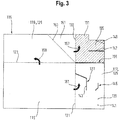
- the Fig. 3 shows a blank for a packaging element for packaging a household appliance.
- the blank 116 is in particular made of cardboard, in particular paper, cardboard and / or cardboard.
- the in the Fig. 3 shown surfaces of the blank 116 correspond to those in the Fig. 2 shown surfaces of the packaging element 113 in the folded state, except that the corresponding surfaces of the in the Fig. 3 shown blank 116 are arranged in a plane.
- the blank 116 has a base 115, a first side surface 117 with a receiving opening 127 and a second side surface 119 with an insertion element 135.
- the first and second side surfaces 117, 119 are integrally formed with the base 115, and are each connected foldably to the base 115.
- the base 115, the first side surface 117 and the second side surface 119 are arranged in a plane.
- the packaging element 113 according to the Fig. 2 can also the blank 116 according to the Fig. 3 one of the first side surface 117 facing away from the third side surface 118 and the second side surface 119 facing away from fourth side surface 120, which are each connected foldably connected to the base 115.
- the in Fig. 3 illustrated insertion section 131 of the second side surface 119 is bent about the Ein Concretehrabroughknickkante 133 in a first direction of buckling 157, in particular by about 90 ° kinked.
- the breakthrough 155 between the Insertion portion 131 and the first side surface 117 the buckling along the first buckling direction 157 is made possible.
- the second side surface 119 comprising the second base surface section 129 with the insertion section 131 bent relative to the second base surface section 129, is folded around the second side folding edge 123 in a second buckling direction 159, in particular by approximately 90 ° kinked.
- the first side surface 117 is bent around the first side crease edge 121 in a third crease direction 161, in particular bent by approximately 90 °. Thereby, the receiving opening 127 of the first side surface 117 can be positioned on the insertion member 135 of the second side surface 119.
- the buckling of the first side surface 117 may also be performed before the second side surface 119 is bent over.
- the insertion member 135 is inserted into the receiving opening 127 to the first side surface 117 and the second side surface 119 in the in the Fig. 2 shown folded state to connect form-fitting with each other.
- Fig. 4 shows a perspective view of a packaging element for packaging a household appliance in a compact state.
- the transition from the folded state to the compact state is made by folding the in Fig. 2 and a folding of the first side surface 117 about the first side crease edge 121, and a folding of the second side surface 119 about the second side crease edge 123.
- the second side surface 119 In the in the Fig. 4 shown compact state of the packaging element 113 is the second side surface 119, in particular the second base surface portion 129 of the second side surface 119 on the base 115 on.
- the first side surface 117 In the in the Fig. 4 shown compact state of the packaging element 113 is the first side surface 117, in particular the first base surface portion 125 of the first side surface 117, at least in sections on the base 115 on.
- the insertion member 135 is further accommodated in the receiving opening 127 in order to connect the first and second side surface 117, 119 form fit with each other.
- first and second side surfaces 117, 119 extend in the in Fig. 4 illustrated compact state of the packaging element 113 is not angled to the base 115, but the first and second side surface 117, 119 extend in the in Fig. 4 shown compact state of the packaging element 113 substantially parallel to the base 115th
Landscapes
- Engineering & Computer Science (AREA)
- Mechanical Engineering (AREA)
- Cartons (AREA)
Abstract
Description
- Die vorliegende Erfindung betrifft ein Verpackungselement zum Verpacken eines Haushaltsgeräts, und ein Haushaltsgerät umfassend ein Verpackungselement.
- Während des Transports eines herkömmlichen Haushaltsgeräts werden Verpackungselemente, insbesondere Kartonagen, verwendet, um die Gerätewandung, insbesondere die Oberseite der Gerätewandung, des Haushaltsgeräts vor einer Beschädigung zu schützen. Derartig Verpackungselemente müssen vor dem Transport auf die Gerätewandung des Haushaltsgeräts aufgebracht, insbesondere verklebt, werden, bzw. nach dem Transport von der Gerätewandung des Haushaltsgeräts wieder entfernt werden.
- In der
DE 41 23 697 A1 ist ein Eckstück zum Schutz von kastenförmigen Gegenständen beim Verpacken und Transportieren offenbart. - In der
DE 44 00 006 A1 ist ein Eckpolster auf Wellpappe offenbart. - Es ist die der Erfindung zugrundeliegende Aufgabe, ein vorteilhaft in einen gefalteten Zustand überführbares Verpackungselement zum Verpacken eines Haushaltsgeräts bereitzustellen.
- Diese Aufgabe wird durch die Gegenstände mit den Merkmalen nach den unabhängigen Ansprüchen gelöst. Vorteilhafte Ausführungsformen sind Gegenstand der abhängigen Ansprüche, der Beschreibung und der Zeichnungen.
- Gemäß einem ersten Aspekt wird die erfindungsgemäße Aufgabe durch ein Verpackungselement zum Verpacken eines Haushaltsgeräts gelöst, wobei das Verpackungselement eine Grundfläche aufweist, wobei das Verpackungselement eine erste Seitenfläche und eine zweite Seitenfläche aufweist, welche einstückig mit der Grundfläche ausgebildet sind, und welche mit der Grundfläche jeweils faltbar verbunden sind, und wobei sich die erste Seitenfläche und die zweite Seitenfläche in einem gefalteten Zustand des Verpackungselements jeweils winklig von der Grundfläche aus erstrecken, wobei die erste Seitenfläche eine Aufnahmeöffnung aufweist, und wobei die zweite Seitenfläche ein Einführelement aufweist, welches ausgebildet ist, in dem gefalteten Zustand des Verpackungselements in der Aufnahmeöffnung der ersten Seitenfläche aufgenommen zu sein, um die erste und zweite Seitenflächen formschlüssig miteinander zu verbinden.
- Dadurch wird der technische Vorteil erreicht, dass durch die formschlüssige Verbindung zwischen der ersten und zweiten Seitenfläche in dem gefalteten Zustand des Verpackungselements eine besonders stabile Anordnung der beiden Seitenflächen gegenüber der Grundfläche sichergestellt werden kann.
- Insbesondere sind die erste und zweite Seitenfläche nicht stoffschlüssig miteinander verbunden, insbesondere nicht miteinander verklebt. Durch den Verzicht auf eine stoffschlüssige Verbindung, insbesondere Verkleben, der beiden Seitenflächen, kann auf Klebstoff verzichtet werden, wodurch eine Ressourcen-schonende Verpackung sichergestellt werden kann.
- Zudem ermöglicht eine formschlüssige Verbindung zwischen der ersten und zweiten Seitenfläche ein vorteilhaftes, insbesondere flaches, Zusammenfalten des Verpackungselements in einen kompakten Zustand.
- Die formschlüssige Verbindung zwischen den beiden Seitenflächen wird durch die Aufnahme des Einführelements der zweiten Seitenfläche in der Aufnahmeöffnung der ersten Seitenfläche sichergestellt. Hierbei können in dem gefalteten Zustand des Verpackungselements auf die erste und zweite Seitenfläche wirkenden Zug- und Druckkräfte besonders wirksam aufgenommen werden, ohne dass sich die formschlüssige Verbindung zwischen den beiden Seitenflächen löst.
- Das Verpackungselement ist insbesondere einstückig aus Kartonage, insbesondere Papier, Pappe und/oder Karton, gefertigt.
- Unter einem Haushaltsgerät wird ein Gerät verstanden, das zur Haushaltsführung eingesetzt wird. Das kann ein Haushaltsgroßgerät sein, wie beispielsweise eine Waschmaschine, ein Wäschetrockner, eine Geschirrspülmaschine, ein Herd, ein Backofen. Das kann aber auch ein Haushaltskleingerät sein, wie beispielsweise ein Warmwasserbereiter, ein Kaffeevollautomat, eine Küchenmaschine oder ein Teppichreinigungsgerät.
- In einer vorteilhaften Ausführungsform weist die zweite Seitenfläche einen zweiten Grundflächenabschnitt auf, welcher faltbar mit der Grundfläche verbunden ist, und weist die zweite Seitenfläche einen Einführabschnitt auf, welcher faltbar mit dem zweiten Grundflächenabschnitt verbunden ist, wobei der Einführabschnitt das Einführelement aufweist, und wobei sich insbesondere der Einführabschnitt der zweiten Seitenfläche und die erste Seitenfläche in dem gefalteten Zustand des Verpackungselements zumindest abschnittsweise überdecken.
- Dadurch wird der technische Vorteil erreicht, dass durch ein Falten des Einführabschnitts gegenüber dem zweiten Grundflächenabschnitt das an dem Einführabschnitt angeordnete Einführelement vorteilhaft an der Aufnahmeöffnung der ersten Seitenfläche positioniert werden kann. Hierbei erstreckt sich der Einführabschnitt in dem gefalteten Zustand des Verpackungselements insbesondere parallel zu der ersten Seitenfläche. Hierbei erstreckt sich der Einführabschnitt in dem gefalteten Zustand des Verpackungselements insbesondere winklig, insbesondere orthogonal, zu dem zweiten Grundflächenabschnitt und/oder zu der Grundfläche.
- In einer vorteilhaften Ausführungsform ist der zweite Grundflächenabschnitt durch eine zweite Seitenknickkante faltbar mit der Grundfläche verbunden, und ist der Einführabschnitt durch eine Einführabschnittknickkante faltbar mit dem zweiten Grundflächenabschnitt verbunden, wobei sich die zweite Seitenknickkante und die Einführabschnittknickkante winklig, insbesondere orthogonal, zueinander erstrecken.
- Dadurch wird der technische Vorteil erreicht, dass durch ein Knicken des Einführabschnitts um die Einführabschnittknickkante und durch ein Knicken des zweiten Grundflächenabschnitts um die zweite Seitenknickkante eine besonders wirksame Positionierung des Einführabschnitts an der ersten Seitenfläche sichergestellt wird.
- In einer vorteilhaften Ausführungsform weist der zweite Grundflächenabschnitt einen Verbindungsabschnitt auf, welcher mit dem Einführabschnitt verbunden ist, wobei der Einführabschnitt durch die Einführabschnittknickkante faltbar mit dem Verbindungsabschnitt verbunden ist, wobei der Verbindungsabschnitt um eine Verbindungsabschnittsknickkante faltbar ist, um in einem kompakten Zustand des Verpackungselements die erste und zweite Seitenfläche mit der Grundfläche in Anlage zu bringen, wobei sich die Verbindungsabschnittsknickkante insbesondere winklig zu der zweite Seitenknickkante und/oder insbesondere winklig zu der Einführabschnittknickkante erstreckt.
- Dadurch wird der technische Vorteil erreicht, dass durch ein Knicken des Verbindungsabschnitts um die Verbindungsabschnittsknickkante das Verpackungselement aus dem gefalteten Zustand, in dem sich die erste und zweite Seitenfläche jeweils winklig zu der Grundfläche erstreckt, in den kompakten Zustand überführt werden kann, in dem die erste und zweite Seitenfläche mit der Grundfläche in Anlage gebracht werden. Somit kann das Verpackungselement in dem kompakten Zustand flach gelagert werden.
- In einer vorteilhaften Ausführungsform weist die erste Seitenfläche einen ersten Grundflächenabschnitt auf, welcher durch eine erste Seitenknickkante faltbar mit der Grundfläche verbunden ist, wobei der erste Grundflächenabschnitt die Aufnahmeöffnung aufweist.
- Dadurch wird der technische Vorteil erreicht, dass die an dem ersten Grundflächenabschnitt angeordnete Aufnahmeöffnung das Einführelement wirksam aufnehmen kann.
- In einer vorteilhaften Ausführungsform sind die erste Seitenfläche und die zweite Seitenfläche durch einen Durchbruch voneinander getrennt, wobei insbesondere der erste Grundflächenabschnitt der ersten Seitenfläche von dem Einführabschnitt der zweiten Seitenfläche durch den Durchbruch voneinander getrennt ist.
- Dadurch wird der technische Vorteil erreicht, dass durch den Durchbruch zwischen der ersten und zweiten Seitenfläche ein Falten der ersten und zweiten Seitenfläche unabhängig voneinander gewährleistet werden kann.
- In einer vorteilhaften Ausführungsform ist das Einführelement als eine Einführlasche ausgebildet, welche im gefalteten Zustand des Verpackungselements in der als eine Einführtasche ausgebildeten Aufnahmeöffnung aufgenommen ist, wobei die Einführtasche insbesondere als Einführschlitz ausgebildet ist.
- Dadurch wird der technische Vorteil erreicht, dass durch das Einführen der Einführlasche in die Einführtasche eine besonders wirksame formschlüssige Verbindung zwischen den beiden Seitenflächen sichergestellt werden kann.
- In einer vorteilhaften Ausführungsform begrenzen die Grundfläche, die erste Seitenfläche und die zweite Seitenfläche einen Verpackungsinnenraum, und weist die erste Seitenfläche eine dem Verpackungsinnenraum zugewandte Innenseite und eine dem Verpackungsinnenraum abgewandte Außenseite auf, wobei das Einführelement im gefalteten Zustand des Verpackungselements von der Innenseite der erste Seitenfläche aus durch die Aufnahmeöffnung geführt ist, oder wobei das Einführelement im gefalteten Zustand des Verpackungselements von der Außenseite der erste Seitenfläche aus durch die Aufnahmeöffnung geführt ist.
- Dadurch wird der technische Vorteil erreicht, dass eine wirksame formschlüssige Verbindung zwischen den beiden Seitenflächen sichergestellt werden kann.
- In einer vorteilhaften Ausführungsform ist die Aufnahmeöffnung durch eine Haltekante zumindest abschnittsweise begrenzt, wobei das Einführelement im gefalteten Zustand des Verpackungselements an der Haltekante anliegt, um die formschlüssige Verbindung zwischen der ersten und zweiten Seitenfläche bereitzustellen.
- Dadurch wird der technische Vorteil erreicht, dass durch das Anliegen des Einführelements an der Haltekante eine wirksame Aufnahme von Zug-, und/oder Druckkräften sichergestellt werden kann.
- In einer vorteilhaften Ausführungsform weist die erste Seitenfläche eine zweite Aufnahmeöffnung auf, und ist das Einführelement im gefalteten Zustand des Verpackungselements in der Aufnahmeöffnung der ersten Seitenfläche und in der zweiten Aufnahmeöffnung der ersten Seitenfläche aufgenommen, wobei die zweite Aufnahmeöffnung insbesondere als ein abgewinkelter Aufnahmeschlitz ausgebildet ist.
- Dadurch wird der technische Vorteil erreicht, dass durch die Aufnahme des Einführelements in die Aufnahmeöffnung und in die weitere Aufnahmeöffnung eine besonders stabile formschlüssige Verbindung zwischen der ersten und zweiten Seitenfläche sichergestellt werden kann.
- In einer vorteilhaften Ausführungsform weist das Einführelement eine erste Einführspitze auf, welche im gefalteten Zustand des Verpackungselements in der Aufnahmeöffnung aufgenommen ist, und weist das Einführelement eine zweite Einführspitze auf, welche im gefalteten Zustand des Verpackungselements in der zweiten Aufnahmeöffnung aufgenommen ist.
- Dadurch wird der technische Vorteil erreicht, dass durch die beiden Einführspitzen des Einführelements eine wirksame Aufnahme des Einführelements in der Aufnahmeöffnung und in der weiteren Aufnahmeöffnung sichergestellt werden kann.
- In einer vorteilhaften Ausführungsform weist das Verpackungselement eine der ersten Seitenfläche abgewandte dritte Seitenfläche und eine der zweiten Seitenfläche abgewandte vierte Seitenfläche auf, welche einstückig mit der Grundfläche ausgebildet sind, und welche mit der Grundfläche jeweils faltbar verbunden sind, wobei sich die dritte Seitenfläche und die vierte Seitenfläche in dem gefalteten Zustand des Verpackungselements jeweils winklig von der Grundfläche aus erstrecken, wobei die dritte Seitenfläche eine Aufnahmeöffnung und die vierte Seitenfläche ein Einführelement aufweist, welches ausgebildet ist, in dem gefalteten Zustand des Verpackungselements in der Aufnahmeöffnung der ersten Seitenfläche aufgenommen zu sein, um die dritte und vierte Seitenflächen formschlüssig miteinander zu verbinden, und/oder wobei die dritte Seitenfläche eine weitere Aufnahmeöffnung und die zweite Seitenfläche ein weiteres Einführelement aufweist, welches ausgebildet ist, in dem gefalteten Zustand des Verpackungselements in der weiteren Aufnahmeöffnung der dritten Seitenfläche aufgenommen zu sein, um die dritte und zweite Seitenflächen formschlüssig miteinander zu verbinden,
- und/oder wobei die vierte Seitenfläche eine weiteres Einführelement und die erste Seitenfläche eine weitere Aufnahmeöffnung aufweist, wobei das weitere Einführelement ausgebildet ist, in dem gefalteten Zustand des Verpackungselements in der weiteren Aufnahmeöffnung der ersten Seitenfläche aufgenommen zu sein, um die vierte und erste Seitenflächen formschlüssig miteinander zu verbinden.
- Dadurch wird der technische Vorteil erreicht, dass durch die Anordnung von weiteren Einführelementen an der zweiten und/oder vierten Seitenfläche, bzw. die Anordnung von weiteren Aufnahmeelementen an der ersten und/oder dritten Seitenfläche, besonders vorteilhafte formschlüssige Verbindungen zwischen den vier Seitenflächen des Verpackungselements sichergestellt werden können.
- In einer vorteilhaften Ausführungsform ist das Verpackungselement als ein Hohlquader geformt, welcher ausgebildet ist, auf eine Oberseite einer Gerätewandung des Haushaltsgeräts aufgesetzt zu werden.
- Dadurch wird der technische Vorteil erreicht, dass ein auf die Oberseite einer Gerätewandung eines Haushaltsgeräts aufgesetztes Verpackungselement die Oberseite, sowie die an der Oberseite angeordneten Wandungsecken vorteilhaft vor einer Beschädigung schützt.
- Gemäß einem zweiten Aspekt wird die erfindungsgemäße Aufgabe durch einen Zuschnitt für ein Verpackungselement nach dem ersten Aspekt gelöst, wobei der Zuschnitt eine Grundfläche aufweist, wobei der Zuschnitt eine erste Seitenfläche mit einer Aufnahmeöffnung und eine zweite Seitenfläche mit einem Einführelement aufweist, welche einstückig mit der Grundfläche ausgebildet sind, und welche mit der Grundfläche jeweils faltbar verbunden sind, wobei die Grundfläche, die erste Seitenfläche und die zweite Seitenfläche in einer Ebene angeordnet sind.
- Dadurch wird der technische Vorteil erreicht, dass die erste und zweite Seitenfläche durch ein Falten der faltbaren Verbindung mit der Grundfläche wirksam gefaltet werden können, so dass sich die Seitenflächen in dem gefalteten Zustand des Verpackungselements winklig zu der Grundfläche erstrecken. Die in Bezug auf das Verpackungselement beschriebenen vorteilhaften Ausführungsformen gelten ebenso für den Zuschnitt des Verpackungselements als vorteilhafte Ausführungsformen.
- Gemäß einem dritten Aspekt wird die erfindungsgemäße Aufgabe durch ein Haushaltsgerät umfassend ein Verpackungselement nach dem ersten Aspekt gelöst, wobei das Haushaltsgerät eine Gerätewandung aufweist, wobei das Verpackungselement zumindest abschnittsweise mit der Gerätewandung verbunden ist, wobei das Verpackungselement insbesondere auf eine Oberseite der Gerätewandung aufgesetzt ist.
- Dadurch wird der technische Vorteil erreicht, dass das Verpackungselement das Haushaltsgerät, insbesondere die Oberseite der Gerätewandung des Haushaltsgeräts, besonders vorteilhaft vor einer Beschädigung schützt.
- Ausführungsbeispiele der Erfindung sind in den Zeichnungen dargestellt und werden im Folgenden näher beschrieben.
- Es zeigen:
- Fig. 1
- eine schematische Ansicht eines Haushaltsgeräts mit einem Verpackungselement;
- Fig. 2
- eine perspektivische Ansicht eines Verpackungselements zum Verpacken eines Haushaltsgeräts in einem gefalteten Zustand;
- Fig. 3
- eine perspektivische Ansicht eines Zuschnitts für ein Verpackungselement zum Verpacken eines Haushaltsgeräts; und
- Fig. 4
- eine perspektivische Ansicht eines Verpackungselements zum Verpacken eines Haushaltsgeräts in einem kompakten Zustand.
-
Fig. 1 zeigt eine schematische Ansicht eines allgemeinen Haushaltsgeräts 100, wie z.B. eine Waschmaschine. Das als Waschmaschine ausgebildete Haushaltsgerät 100 umfasst eine Einspülschale 101, in die Waschmittel oder andere flüssige Substanzen eingefüllt werden können. Das als Waschmaschine ausgebildete Haushaltsgerät 100 umfasst eine Tür 103 zum Beladen des Haushaltsgeräts 100 mit Wäsche, wobei die Tür 103 eine Geräteöffnung 105 des Haushaltsgeräts 100 verschließt. - Das Haushaltsgerät 100 weist eine Gerätewandung 107 auf, welche im vorliegenden Fall sechs Wandungsseiten 109 und acht Wandungsecken 111 umfasst, wobei aus darstellungstechnischen Gründen in der
Fig. 1 nur einige der Wandungsseiten 109 und nur einige der Wandungsecken 111 gezeigt sind. - Um den sicheren Transport des Haushaltsgeräts 100 zum Endnutzer sicherzustellen, werden üblicherweise Verpackungselemente 113 verwendet, welche gewährleisten, dass das Haushaltsgerät 100, bzw. die Gerätewandung 107 des Haushaltsgeräts 100, nicht beschädigt wird. Derartige Verpackungselemente 113 sind insbesondere aus Kartonage, insbesondere Papier, Pappe und/oder Karton, gefertigt.
- Das Verpackungselement 113 gemäß der vorliegenden Offenbarung ist insbesondere als ein Hohlquader geformt, welcher auf eine Oberseite 112 der Gerätewandung 107 des Haushaltsgeräts 100 aufgesetzt ist, und welcher somit auf die an der Oberseite 112 angeordneten Wandungsecken 111 des Haushaltsgeräts 100 aufgesetzt ist.
- Wie in der
Fig. 1 dargestellt ist, weist das Verpackungselement 113 eine Grundfläche 115 auf, welche die Oberseite 112 des Haushaltsgeräts 100 abdeckt, sowie eine erste Seitenfläche 117 und eine zweite Seitenfläche 119 auf. Zudem weist das Verpackungselement 113 eine der ersten Seitenfläche 117 abgewandte dritte Seitenfläche 118 und eine der zweiten Seitenfläche 119 abgewandte vierte Seitenfläche 120 auf, wobei in derFig. 1 die dritte und vierte Seitenfläche 118, 120 aufgrund der Darstellungsperspektive nicht einsehbar sind. - In dem in
Fig. 1 dargestellten gefalteten Zustand des Verpackungselements 113 erstrecken sich die erste Seitenfläche 117 und die zweite Seitenfläche 119, bzw. die dritte Seitenfläche 118 und die vierte Seitenfläche 120 jeweils winklig von der Grundfläche 115 aus. - An einer der Grundfläche 115 abgewandten Seite ist das Verpackungselement 113 offen, um auf die Oberseite 112 der Gerätewandung 107 des Haushaltsgeräts 100 aufgesetzt zu werden.
- Durch das Verpackungselement 113 kann ein wirksamer Schutz der Gerätewandung 107, insbesondere der Oberseite 112 der Gerätewandung 107, des Haushaltsgeräts 100, gewährleistet werden.
- Die
Fig. 2 zeigt eine perspektivische Ansicht eines Verpackungselements zum Verpacken eines Haushaltsgeräts in einem gefalteten Zustand. Das Verpackungselement 113 ist insbesondere aus Kartonage, insbesondere Papier, Pappe und/oder Karton, gefertigt. - Das Verpackungselement 113 weist eine Grundfläche 115, eine erste Seitenfläche 117 und eine zweite Seitenfläche 119 auf. Die erste und zweite Seitenfläche 117, 119 sind einstückig mit der Grundfläche 115 ausgebildet, und die erste und zweite Seitenfläche 117, 119 sind jeweils mit der Grundfläche 115 faltbar verbunden.
- Auch wenn dies in
Fig. 2 nicht dargestellt ist, kann das Verpackungselement 113 in einer Ausführungsform eine der ersten Seitenfläche 117 abgewandte dritte Seitenfläche 118 und eine der zweiten Seitenfläche 119 abgewandte vierte Seitenfläche 120 aufweisen, wobei die dritte und vierte Seitenfläche 118, 120 einstückig mit der Grundfläche 115 ausgebildet sind, und jeweils mit der Grundfläche 115 faltbar verbunden sind. - In dem in
Fig. 2 dargestellten gefalteten Zustand des Verpackungselements 113 erstrecken sich die erste Seitenfläche 117 und die zweite Seitenfläche 119, bzw. die optional vorhandene dritte Seitenfläche 118 und die optional vorhandene vierte Seitenfläche 120 jeweils winklig von der Grundfläche 115 aus. - Die erste Seitenfläche 117 ist durch eine erste Seitenknickkante 121 faltbar mit der Grundfläche 115 verbunden. Die zweite Seitenfläche 119 ist durch eine zweite Seitenknickkante 123 faltbar mit der Grundfläche 115 verbunden. In dem in
Fig. 2 dargestellten gefalteten Zustand des Verpackungselements 113 erstreckt sich die erste Seitenfläche 117 winklig, insbesondere orthogonal, zu der Grundfläche 115 und erstreckt sich die zweite Seitenfläche 119 winklig, insbesondere orthogonal, zu der Grundfläche 115. - Die erste Seitenfläche 117 weist einen ersten Grundflächenabschnitt 125 auf, welcher durch die erste Seitenknickkante 121 faltbar mit der Grundfläche 115 verbunden ist, wobei der erste Grundflächenabschnitt 125 eine Aufnahmeöffnung 127 aufweist. Die Aufnahmeöffnung 127 der ersten Seitenfläche 117 ist in
Fig. 2 nur schematisch gezeigt und ist insbesondere als eine Einführtasche ausgebildet, wobei die Einführtasche insbesondere als ein Einführschlitz ausgebildet ist. - Die zweite Seitenfläche 119 weist einen zweiten Grundflächenabschnitt 129 auf, welcher durch die zweite Seitenknickkante 123 faltbar mit der Grundfläche 115 verbunden ist.
- Die zweite Seitenfläche 119 weist ferner einen Einführabschnitt 131 auf, welcher faltbar mit dem zweiten Grundflächenabschnitt 129 verbunden ist. Der Einführabschnitt 131 ist durch eine Einführabschnittknickkante 133 faltbar mit dem zweiten Grundflächenabschnitt 129 verbunden. Hierbei erstrecken sich die zweite Seitenknickkante 123 und die Einführabschnittknickkante 133 und/oder erste Seitenknickkante 121 winklig, insbesondere orthogonal, zueinander.
- Die zweite Seitenfläche 119, insbesondere der Einführabschnitt 131 der zweiten Seitenfläche 119, weist ein Einführelement 135 auf, wobei das Einführelement 135 insbesondere als eine Einführlasche ausgebildet ist.
- In dem in
Fig. 2 dargestellten gefalteten Zustand des Verpackungselements 113 ist das Einführelement 135 der zweiten Seitenfläche 119, insbesondere die Einführlasche, in der Aufnahmeöffnung 127 der ersten Seitenfläche 117, insbesondere der Einführtasche, aufgenommen. - Somit wird durch die Aufnahme des Einführelements 135 in der Aufnahmeöffnung 127 eine stabile formschlüssige Verbindung zwischen der ersten Seitenfläche 117 und der zweiten Seitenfläche 119 sichergestellt. Durch die vorteilhaft ausgebildete formschlüssige Verbindung kann auf den Einsatz von Klebstoffen zum Verbinden der ersten und zweiten Seitenfläche 117, 119 verzichtet werden, und dennoch eine stabile Ausbildung des Verpackungselements 113 im gefalteten Zustand sichergestellt werden, wodurch ein Haushaltsgerät 100 durch das Verpackungselement 113 wirksam verpackt werden kann.
- Wie aus der
Fig. 2 ersichtlich ist, überdeckt der Einführabschnitt 131 der zweiten Seitenfläche 119 insbesondere die erste Seitenfläche 117 zumindest abschnittsweise im gefalteten Zustand des Verpackungselements 113. Um das inFig. 2 dargestellte Umfalten des Einführabschnitts 131 über die erste Seitenfläche 117 zu ermöglichen, sind der erste Grundflächenabschnitt 125 der ersten Seitenfläche 117 von dem Einführabschnitt 131 der zweiten Seitenfläche 119 durch einen Durchbruch 155 voneinander getrennt. - Die Grundfläche 115, die erste Seitenfläche 117 und die zweite Seitenfläche 119 begrenzen einen Verpackungsinnenraum 137 des Verpackungselements 113. Die erste Seitenfläche 117 weist im gefalteten Zustand des Verpackungselements 113 eine dem Verpackungsinnenraum 113 zugewandte Innenseite 139 und eine dem Verpackungsinnenraum 113 abgewandte Außenseite 141 auf. In der in
Fig. 2 gezeigten Darstellung ist das Einführelement 135 im gefalteten Zustand des Verpackungselements 113 von der Innenseite 139 der ersten Seitenfläche 117 aus durch die Aufnahmeöffnung 127 geführt. Auch wenn dies in derFig. 2 nicht dargestellt ist, kann das Einführelement 135 alternativ auch im gefalteten Zustand des Verpackungselements 113 von der Außenseite 141 der ersten Seitenfläche 117 aus durch die Aufnahmeöffnung 127 geführt sein. - Die Aufnahmeöffnung 127 in der ersten Seitenfläche 117 ist durch eine Haltekante 143 zumindest abschnittsweise begrenzt, wobei das Einführelement 135 im gefalteten Zustand des Verpackungselements 113 an der Haltekante 143 anliegt, um die formschlüssige Verbindung zwischen der ersten und zweiten Seitenfläche 117, 119 bereitzustellen.
- Die erste Seitenfläche 117 weist insbesondere eine zweite Aufnahmeöffnung 145 auf, welche insbesondere als ein abgewinkelter Aufnahmeschlitz ausgebildet ist. Wie in der
Fig. 2 dargestellt ist, ist das Einführelement 135 im gefalteten Zustand des Verpackungselements 113 in der Aufnahmeöffnung 127 der ersten Seitenfläche 117 und in der zweiten Aufnahmeöffnung 145 der ersten Seitenfläche 117 aufgenommen. Hierbei ist insbesondere eine erste Einführspitze 147 des Einführelements 135 im gefalteten Zustand des Verpackungselements 113 in der Aufnahmeöffnung 127 aufgenommen, und ist insbesondere eine zweite Einführspitze 149 des Einführelements 135 im gefalteten Zustand des Verpackungselements 113 in der zweiten Aufnahmeöffnung 145 aufgenommen. - Ferner weist der zweite Grundflächenabschnitt 129 der zweiten Seitenfläche 119 einen Verbindungsabschnitt 151 auf, welcher mit dem Einführabschnitt 131 der zweiten Seitenfläche 119 verbunden ist. Der Einführabschnitt 131 ist durch die Einführabschnittknickkante 133 faltbar mit dem Verbindungsabschnitt 151 verbunden.
- Der Verbindungsabschnitt 151 ist um eine Verbindungsabschnittsknickkante 153 faltbar, um in einem in
Fig. 2 nicht dargestellten kompakten Zustand des Verpackungselements 113 die erste und zweite Seitenfläche 117, 119 mit der Grundfläche 115 in Anlage zu bringen. Hier erstreckt sich die Verbindungsabschnittsknickkante 153 insbesondere winklig zu der zweiten Seitenknickkante 123 und/oder winklig zu der Einführabschnittknickkante 133. - Die optional vorhandene dritte Seitenfläche 118 des Verpackungselements 113, welche der ersten Seitenfläche 117 abgewandt ist, kann insbesondere entsprechend der ersten Seitenfläche 117 ausgestaltet sein. Die optional vorhandene vierte Seitenfläche 120 des Verpackungselements 113, welche der zweiten Seitenfläche 119 abgewandt ist, kann insbesondere entsprechend der zweiten Seitenfläche 119 ausgestaltet sein.
- Hierbei kann insbesondere die vierte Seitenfläche 120 ein weiteres Einführelement 135 aufweisen, welches in einer weiteren Aufnahmeöffnung 127 der dritten Seitenfläche 118 aufgenommen ist. Alternativ oder zusätzlich kann die zweite Seitenfläche 119 ein weiteres Einführelement 135 aufweisen, welches in einer weiteren Aufnahmeöffnung 127 der dritten Seitenfläche 118 aufgenommen ist. Alternativ oder zusätzlich kann die erste Seitenfläche 117 eine weitere Aufnahmeöffnung 127 aufweisen, in welche ein weiteres Einführelement 135 der vierten Seitenfläche 120 aufgenommen ist.
- Für die Ausgestaltung der Einführelemente 135 und Aufnahmeöffnungen 127 wird auf die Ausführungen in Bezug auf das Einführelement 135 der zweiten Seitenfläche 119 und in Bezug auf die Aufnahmeöffnung 127 der ersten Seitenfläche 117 verwiesen.
- Die
Fig. 3 zeigt einen Zuschnitt für ein Verpackungselement zum Verpacken eines Haushaltsgeräts. Der Zuschnitt 116 ist insbesondere aus Kartonage, insbesondere Papier, Pappe und/oder Karton, gefertigt. - Die in der
Fig. 3 gezeigten Flächen des Zuschnitts 116 entsprechen den in derFig. 2 gezeigten Flächen des Verpackungselements 113 in dem gefalteten Zustand, bis darauf, dass die entsprechenden Flächen des in derFig. 3 gezeigten Zuschnitts 116 in einer Ebene angeordnet sind. - Der Zuschnitt 116 weist eine Grundfläche 115, eine erste Seitenfläche 117 mit einer Aufnahmeöffnung 127 und eine zweite Seitenfläche 119 mit einem Einführelement 135 auf. Die erste und zweite Seitenfläche 117, 119 sind einstückig mit der Grundfläche 115 ausgebildet, und sind jeweils mit der Grundfläche 115 faltbar verbunden sind. In dem Zuschnitt 116 sind die Grundfläche 115, die erste Seitenfläche 117 und die zweite Seitenfläche 119 in einer Ebene angeordnet.
- Ebenso wie das Verpackungselement 113 gemäß der
Fig. 2 kann auch der Zuschnitt 116 gemäß derFig. 3 eine der ersten Seitenfläche 117 abgewandte dritte Seitenfläche 118 und einer der zweiten Seitenfläche 119 abgewandte vierte Seitenfläche 120 aufweisen, welche jeweils faltbar mit der Grundfläche 115 verbunden sind. - In Bezug auf die Seitenknickkanten 121, 123, die Grundflächenabschnitte 125, 129, den Einführabschnitt 131, die Einführabschnittknickkante 133, den Verbindungsabschnitt 151, die Verbindungsabschnittsknickkante 153, sowie die Ausgestaltung des Einführelements 135 und der Aufnahmeöffnung 127 wird auf die Ausführungen zur
Fig. 2 verwiesen. - Der Übergang von dem in
Fig. 3 dargestellten Zuschnitt 116 in das in derFig. 2 dargestellte Verpackungselement 113 in dem gefalteten Zustand wird im Rahmen der folgenden Schritte durchgeführt. - In einem ersten Schritt wird der in
Fig. 3 dargestellte Einführabschnitt 131 der zweiten Seitenfläche 119 um die Einführabschnittknickkante 133 in einer ersten Knickrichtung 157 geknickt, insbesondere um ca. 90° geknickt. Durch den Durchbruch 155 zwischen dem Einführabschnitt 131 und der ersten Seitenfläche 117 wird das Knicken entlang der ersten Knickrichtung 157 ermöglicht. - In einem sich an den ersten Schritt anschließenden zweiten Schritt wird die zweite Seitenfläche 119, umfassend den zweiten Grundflächenabschnitt 129 mit dem gegenüber dem zweiten Grundflächenabschnitt 129 abgeknickten Einführabschnitt 131, um die zweite Seitenknickkante 123 in einer zweiten Knickrichtung 159 geknickt, insbesondere um ca. 90° geknickt.
- In einem sich an den zweiten Schritt anschließenden dritten Schritt wird die erste Seitenfläche 117 um die erste Seitenknickkante 121 in einer dritten Knickrichtung 161 geknickt, insbesondere um ca. 90° geknickt. Dadurch kann die Aufnahmeöffnung 127 der ersten Seitenfläche 117 an dem Einführelement 135 der zweiten Seitenfläche 119 positioniert werden.
- Alternativ kann das Umknicken der ersten Seitenfläche 117 auch vor dem Umknicken der zweiten Seitenfläche 119 durchgeführt werden.
- In einem abschließenden Schritt wird das Einführelement 135 in die Aufnahmeöffnung 127 eingeführt, um die erste Seitenfläche 117 und die zweite Seitenfläche 119 in dem in der
Fig. 2 dargestellten gefalteten Zustand formschlüssig miteinander zu verbinden. -
Fig. 4 zeigt eine perspektivische Ansicht eines Verpackungselements zum Verpacken eines Haushaltsgeräts in einem kompakten Zustand. - Das in der
Fig. 2 dargestellte Verpackungselement 113 in dem gefalteten Zustand kann in das in derFig. 4 dargestellte Verpackungselement 113 in dem kompakten Zustand überführt werden. - Der Übergang von dem gefalteten Zustand in den kompakten Zustand erfolgt durch ein Falten des in
Fig. 2 dargestellten Verbindungsabschnitts 151 um eine Verbindungsabschnittsknickkante 153, sowie einem Falten der ersten Seitenfläche 117 um die erste Seitenknickkante 121, und einem Falten der zweiten Seitenfläche 119 um die zweite Seitenknickkante 123. - In dem in der
Fig. 4 dargestellten kompakten Zustand des Verpackungselements 113 liegt die zweite Seitenfläche 119, insbesondere der zweite Grundflächenabschnitt 129 der zweiten Seitenfläche 119 auf der Grundfläche 115 auf. - In dem in der
Fig. 4 dargestellten kompakten Zustand des Verpackungselements 113 liegt die erste Seitenfläche 117, insbesondere der erste Grundflächenabschnitt 125 der ersten Seitenfläche 117, zumindest abschnittsweise auf der Grundfläche 115 auf. - In dem in der
Fig. 4 dargestellten kompakten Zustand des Verpackungselements 113 liegt der Einführabschnitt 131 der ersten Seitenfläche 117 auf der zweiten Seitenfläche 119 auf. - In dem in
Fig. 4 dargestellten kompakten Zustand des Verpackungselements 113 ist das Einführelement 135 weiterhin in der Aufnahmeöffnung 127 aufgenommen, um die erste und zweite Seitenfläche 117, 119 formschlüssig miteinander zu verbinden. - Somit erstrecken sich die erste und zweite Seitenfläche 117, 119 in dem in
Fig. 4 dargestellten kompakten Zustand des Verpackungselements 113 nicht winklig zu der Grundfläche 115, sondern die erste und zweite Seitenfläche 117, 119 verlaufen in dem inFig. 4 dargestellten kompakten Zustand des Verpackungselements 113 im Wesentlichen parallel zu der Grundfläche 115. - Alle in Verbindung mit einzelnen Ausführungsformen der Erfindung erläuterten und gezeigten Merkmale können in unterschiedlicher Kombination in dem erfindungsgemäßen Gegenstand vorgesehen sein, um gleichzeitig deren vorteilhafte Wirkungen zu realisieren.
- Der Schutzbereich der vorliegenden Erfindung ist durch die Ansprüche gegeben und wird durch die in der Beschreibung erläuterten oder den Figuren gezeigten Merkmale nicht beschränkt.
-
- 100
- Haushaltsgerät
- 101
- Einspülschale
- 103
- Tür
- 105
- Geräteöffnung
- 107
- Gerätewandung
- 109
- Wandungsseite
- 111
- Wandungsecke
- 112
- Oberseite der Gerätewandung
- 113
- Verpackungselement
- 115
- Grundfläche
- 116
- Zuschnitt
- 117
- Erste Seitenfläche
- 118
- Dritte Seitenfläche
- 119
- Zweite Seitenfläche
- 120
- Vierte Seitenfläche
- 121
- Erste Seitenknickkante
- 123
- Zweite Seitenknickkante
- 125
- Erster Grundflächenabschnitt
- 127
- Aufnahmeöffnung
- 129
- Zweiter Grundflächenabschnitt
- 131
- Einführabschnitt
- 133
- Einführabschnittknickkante
- 135
- Einführelement
- 137
- Verpackungsinnenraum
- 139
- Innenseite der ersten Seitenfläche
- 141
- Außenseite der ersten Seitenfläche
- 143
- Haltekante
- 145
- Weitere Aufnahmeöffnung
- 147
- Erste Einführspitze
- 149
- Zweite Einführspitze
- 151
- Verbindungsabschnitt
- 153
- Verbindungsabschnittsknickkante
- 155
- Durchbruch
- 157
- Erste Knickrichtung
- 159
- Zweite Knickrichtung
- 161
- Dritte Knickrichtung
Claims (15)
- Verpackungselement (113) zum Verpacken eines Haushaltsgeräts (100), wobei das Verpackungselement (113) eine Grundfläche (115) aufweist, wobei das Verpackungselement (113) eine erste Seitenfläche (117) und eine zweite Seitenfläche (119) aufweist, welche einstückig mit der Grundfläche (115) ausgebildet sind, und welche mit der Grundfläche (115) jeweils faltbar verbunden sind, und wobei sich die erste Seitenfläche (117) und die zweite Seitenfläche (119) in einem gefalteten Zustand des Verpackungselements (113) jeweils winklig von der Grundfläche (115) aus erstrecken, dadurch gekennzeichnet, dass
die erste Seitenfläche (117) eine Aufnahmeöffnung (127) aufweist, und dass
die zweite Seitenfläche (119) ein Einführelement (135) aufweist, welches ausgebildet ist, in dem gefalteten Zustand des Verpackungselements (113) in der Aufnahmeöffnung (127) der ersten Seitenfläche (117) aufgenommen zu sein, um die erste und zweite Seitenflächen (117, 119) formschlüssig miteinander zu verbinden. - Verpackungselement (113) nach Anspruch 1, dadurch gekennzeichnet, dass die zweite Seitenfläche (119) einen zweiten Grundflächenabschnitt (129) aufweist, welcher faltbar mit der Grundfläche (115) verbunden ist, und dass die zweite Seitenfläche (119) einen Einführabschnitt (131) aufweist, welcher faltbar mit dem zweiten Grundflächenabschnitt (129) verbunden ist, wobei der Einführabschnitt (131) das Einführelement (135) aufweist, und wobei sich insbesondere der Einführabschnitt (131) der zweiten Seitenfläche (119) und die erste Seitenfläche (117) in dem gefalteten Zustand des Verpackungselements (113) zumindest abschnittsweise überdecken.
- Verpackungselement (113) nach Anspruch 2, dadurch gekennzeichnet, dass der zweite Grundflächenabschnitt (129) durch eine zweite Seitenknickkante (123) faltbar mit der Grundfläche (115) verbunden ist, und dass der Einführabschnitt (131) durch eine Einführabschnittknickkante (133) faltbar mit dem zweiten Grundflächenabschnitt (129) verbunden ist, wobei sich die zweite Seitenknickkante (123) und die Einführabschnittknickkante (133) winklig, insbesondere orthogonal, zueinander erstrecken.
- Verpackungselement (113) nach Anspruch 3 , dadurch gekennzeichnet, dass der zweite Grundflächenabschnitt (129) einen Verbindungsabschnitt (151) aufweist, welcher mit dem Einführabschnitt (131) verbunden ist, wobei der Einführabschnitt (131) durch die Einführabschnittknickkante (133) faltbar mit dem Verbindungsabschnitt (151) verbunden ist, wobei der Verbindungsabschnitt (151) um eine Verbindungsabschnittsknickkante (153) faltbar ist, um in einem kompakten Zustand des Verpackungselements (113) die erste und zweite Seitenfläche (117, 119) mit der Grundfläche (115) in Anlage zu bringen, wobei sich die Verbindungsabschnittsknickkante (153) insbesondere winklig zu der zweiten Seitenknickkante (123) und/oder insbesondere winklig zu der Einführabschnittknickkante (133) erstreckt.
- Verpackungselement (113) nach einem der vorangehenden Ansprüche, dadurch gekennzeichnet, dass die erste Seitenfläche (117) einen ersten Grundflächenabschnitt (125) aufweist, welcher durch eine erste Seitenknickkante (121) faltbar mit der Grundfläche (115) verbunden ist, wobei der erste Grundflächenabschnitt (125) die Aufnahmeöffnung (127) aufweist.
- Verpackungselement (113) nach einem der vorangehenden Ansprüche, dadurch gekennzeichnet, dass die erste Seitenfläche (117) und die zweite Seitenfläche (119) durch einen Durchbruch (155) voneinander getrennt sind, wobei insbesondere der erste Grundflächenabschnitt (125) der ersten Seitenfläche (117) von dem Einführabschnitt (131) der zweiten Seitenfläche (119) durch den Durchbruch (155) voneinander getrennt ist.
- Verpackungselement (113) nach einem der vorangehenden Ansprüche, dadurch gekennzeichnet, dass das Einführelement (135) als eine Einführlasche ausgebildet ist, welche im gefalteten Zustand des Verpackungselements (113) in der als eine Einführtasche ausgebildeten Aufnahmeöffnung (127) aufgenommen ist, wobei die Einführtasche insbesondere als Einführschlitz ausgebildet ist.
- Verpackungselement (113) nach einem der vorangehenden Ansprüche, dadurch gekennzeichnet, dass die Grundfläche (115), die erste Seitenfläche (117) und die zweite Seitenfläche (119) einen Verpackungsinnenraum (137) begrenzen, und dass die erste Seitenfläche (117) eine dem Verpackungsinnenraum (137) zugewandte Innenseite (139) und eine dem Verpackungsinnenraum (137) abgewandte Außenseite (141) aufweist, wobei das Einführelement (135) im gefalteten Zustand des Verpackungselements (113) von der Innenseite (139) der ersten Seitenfläche (117) aus durch die Aufnahmeöffnung (127) geführt ist, oder wobei das Einführelement (135) im gefalteten Zustand des Verpackungselements (113) von der Außenseite (141) der ersten Seitenfläche (117) aus durch die Aufnahmeöffnung (127) geführt ist.
- Verpackungselement (113) nach einem der vorangehenden Ansprüche, dadurch gekennzeichnet, dass die Aufnahmeöffnung (127) durch eine Haltekante (143) zumindest abschnittsweise begrenzt ist, wobei das Einführelement (135) im gefalteten Zustand des Verpackungselements (113) an der Haltekante (143) anliegt, um die formschlüssige Verbindung zwischen der ersten und zweiten Seitenfläche (117, 119) bereitzustellen.
- Verpackungselement (113) nach einem der vorangehenden Ansprüche, dadurch gekennzeichnet, dass die erste Seitenfläche (117) eine zweite Aufnahmeöffnung (145) aufweist, und dass das Einführelement (135) im gefalteten Zustand des Verpackungselements (113) in der Aufnahmeöffnung (127) der ersten Seitenfläche (117) und in der zweiten Aufnahmeöffnung (127) der ersten Seitenfläche (117) aufgenommen ist, wobei die zweite Aufnahmeöffnung (145) insbesondere als ein abgewinkelter Aufnahmeschlitz ausgebildet ist.
- Verpackungselement (113) nach Anspruch 10, dadurch gekennzeichnet, dass das Einführelement (135) eine erste Einführspitze (147) aufweist, welche im gefalteten Zustand des Verpackungselements (113) in der Aufnahmeöffnung (127) aufgenommen ist, und dass das Einführelement (135) eine zweite Einführspitze (149) aufweist, welche im gefalteten Zustand des Verpackungselements (113) in der zweiten Aufnahmeöffnung (145) aufgenommen ist.
- Verpackungselement (113) nach einem der vorangehenden Ansprüche, dadurch gekennzeichnet, dass das Verpackungselement (113) eine der ersten Seitenfläche (117) abgewandte dritte Seitenfläche (118) und eine der zweiten Seitenfläche (119) abgewandte vierte Seitenfläche (120) aufweist, welche einstückig mit der Grundfläche (115) ausgebildet sind, und welche mit der Grundfläche (115) jeweils faltbar verbunden sind, und dass sich die dritte Seitenfläche (118) und die vierte Seitenfläche (120) in dem gefalteten Zustand des Verpackungselements (113) jeweils winklig von der Grundfläche (115) aus erstrecken,
wobei die dritte Seitenfläche (118) eine Aufnahmeöffnung (127) und die vierte Seitenfläche (120) ein Einführelement (135) aufweist, welches ausgebildet ist, in dem gefalteten Zustand des Verpackungselements (113) in der Aufnahmeöffnung (127) der ersten Seitenfläche (117) aufgenommen zu sein, um die dritte und vierte Seitenflächen (118, 120) formschlüssig miteinander zu verbinden,
und/oder wobei die dritte Seitenfläche (118) eine weitere Aufnahmeöffnung (127) und die zweite Seitenfläche (119) ein weiteres Einführelement (135) aufweist, welches ausgebildet ist, in dem gefalteten Zustand des Verpackungselements (113) in der weiteren Aufnahmeöffnung (127) der dritten Seitenfläche (118) aufgenommen zu sein, um die dritte und zweite Seitenflächen (118, 119) formschlüssig miteinander zu verbinden,
und/oder wobei die vierte Seitenfläche (120) eine weiteres Einführelement (135) und die erste Seitenfläche (117) eine weitere Aufnahmeöffnung (127) aufweist, wobei das weitere Einführelement (135) ausgebildet ist, in dem gefalteten Zustand des Verpackungselements (113) in der weiteren Aufnahmeöffnung (127) der ersten Seitenfläche (117) aufgenommen zu sein, um die vierte und erste Seitenflächen (120, 118) formschlüssig miteinander zu verbinden. - Verpackungselement (113) nach einem der vorangehenden Ansprüche, dadurch gekennzeichnet, dass das Verpackungselement (113) als ein Hohlquader geformt ist, welcher ausgebildet ist, auf eine Oberseite (112) einer Gerätewandung (107) des Haushaltsgeräts (100) aufgesetzt zu werden.
- Zuschnitt (116) für ein Verpackungselement (113) nach einem der vorangehenden Ansprüche, dadurch gekennzeichnet, dass der Zuschnitt (116) eine Grundfläche (115) aufweist, wobei der Zuschnitt (116) eine erste Seitenfläche (117) mit einer Aufnahmeöffnung (127) und eine zweite Seitenfläche (119) mit einem Einführelement (135) aufweist, welche einstückig mit der Grundfläche (115) ausgebildet sind, und welche mit der Grundfläche (115) jeweils faltbar verbunden sind, wobei die Grundfläche (115), die erste Seitenfläche (117) und die zweite Seitenfläche (119) in einer Ebene angeordnet sind.
- Haushaltsgerät (100) umfassend einen Verpackungselement (113) nach einem der vorangehenden Ansprüche 1 bis 13, wobei das Haushaltsgerät (100) eine Gerätewandung (107) aufweist, dadurch gekennzeichnet, dass das Verpackungselement (113) zumindest abschnittsweise mit der Gerätewandung (107) verbunden ist, wobei das Verpackungselement (113) insbesondere auf eine Oberseite (112) der Gerätewandung (107) aufgesetzt ist.
Priority Applications (1)
| Application Number | Priority Date | Filing Date | Title |
|---|---|---|---|
| PL19170217T PL3566973T3 (pl) | 2018-05-09 | 2019-04-18 | Element opakowaniowy do pakowania urządzenia gospodarstwa domowego |
Applications Claiming Priority (1)
| Application Number | Priority Date | Filing Date | Title |
|---|---|---|---|
| DE102018207278.7A DE102018207278A1 (de) | 2018-05-09 | 2018-05-09 | Verpackungselement zum Verpacken eines Haushaltsgeräts |
Publications (2)
| Publication Number | Publication Date |
|---|---|
| EP3566973A1 true EP3566973A1 (de) | 2019-11-13 |
| EP3566973B1 EP3566973B1 (de) | 2021-10-27 |
Family
ID=66239880
Family Applications (1)
| Application Number | Title | Priority Date | Filing Date |
|---|---|---|---|
| EP19170217.4A Active EP3566973B1 (de) | 2018-05-09 | 2019-04-18 | Verpackungselement zum verpacken eines haushaltsgeräts |
Country Status (3)
| Country | Link |
|---|---|
| EP (1) | EP3566973B1 (de) |
| DE (1) | DE102018207278A1 (de) |
| PL (1) | PL3566973T3 (de) |
Citations (6)
| Publication number | Priority date | Publication date | Assignee | Title |
|---|---|---|---|---|
| US1672251A (en) * | 1927-04-29 | 1928-06-05 | Charles A Fox | Collapsible box |
| DE4123697A1 (de) | 1991-07-17 | 1992-02-06 | Johann Rueber | Eckstueck zum schutz von kastenfoermigen gegenstaenden beim verpacken und transportieren |
| DE4400006A1 (de) | 1994-01-03 | 1995-07-06 | Karl Mayer Kartonagenfabrik Gm | Eckpolster aus Wellpappe |
| AT1663U1 (de) * | 1997-01-07 | 1997-09-25 | Mosburger Ag | Zuschnitt für den unterteil oder den oberteil einer faltschachtel |
| EP1905701A1 (de) * | 2007-04-20 | 2008-04-02 | Corus Staal BV | Deckel, Verfahren zur Herstellung besagten Deckels und Verfahren zum Verpacken eines Metallblechstapels mit besagtem Deckel |
| EP3251975A1 (de) * | 2016-06-01 | 2017-12-06 | Electrolux Appliances Aktiebolag | Verpackung für ein haushaltsgerät, kit mit verpackung für ein haushaltsgerät und verfahren zum verpacken eines haushaltsgeräts |
Family Cites Families (2)
| Publication number | Priority date | Publication date | Assignee | Title |
|---|---|---|---|---|
| US1755722A (en) * | 1927-10-20 | 1930-04-22 | Bachmann Siegmund | Folding box |
| US2171051A (en) * | 1937-09-08 | 1939-08-29 | F L M Holding Company | Folding paper box |
-
2018
- 2018-05-09 DE DE102018207278.7A patent/DE102018207278A1/de not_active Withdrawn
-
2019
- 2019-04-18 PL PL19170217T patent/PL3566973T3/pl unknown
- 2019-04-18 EP EP19170217.4A patent/EP3566973B1/de active Active
Patent Citations (6)
| Publication number | Priority date | Publication date | Assignee | Title |
|---|---|---|---|---|
| US1672251A (en) * | 1927-04-29 | 1928-06-05 | Charles A Fox | Collapsible box |
| DE4123697A1 (de) | 1991-07-17 | 1992-02-06 | Johann Rueber | Eckstueck zum schutz von kastenfoermigen gegenstaenden beim verpacken und transportieren |
| DE4400006A1 (de) | 1994-01-03 | 1995-07-06 | Karl Mayer Kartonagenfabrik Gm | Eckpolster aus Wellpappe |
| AT1663U1 (de) * | 1997-01-07 | 1997-09-25 | Mosburger Ag | Zuschnitt für den unterteil oder den oberteil einer faltschachtel |
| EP1905701A1 (de) * | 2007-04-20 | 2008-04-02 | Corus Staal BV | Deckel, Verfahren zur Herstellung besagten Deckels und Verfahren zum Verpacken eines Metallblechstapels mit besagtem Deckel |
| EP3251975A1 (de) * | 2016-06-01 | 2017-12-06 | Electrolux Appliances Aktiebolag | Verpackung für ein haushaltsgerät, kit mit verpackung für ein haushaltsgerät und verfahren zum verpacken eines haushaltsgeräts |
Also Published As
| Publication number | Publication date |
|---|---|
| EP3566973B1 (de) | 2021-10-27 |
| DE102018207278A1 (de) | 2019-11-14 |
| PL3566973T3 (pl) | 2022-01-24 |
Similar Documents
| Publication | Publication Date | Title |
|---|---|---|
| DE69719960T2 (de) | Klappschachtel | |
| EP3566973B1 (de) | Verpackungselement zum verpacken eines haushaltsgeräts | |
| DE69917727T2 (de) | Stapel von Feuchttüchern | |
| EP2760314B1 (de) | Steckverbindung | |
| DE212018000422U1 (de) | Akupunkturnadel-Verpackungsstruktur | |
| WO2016026832A1 (de) | Bodenmodul für ein haushaltsgerät | |
| DE29706982U1 (de) | Faltschachtel | |
| DE102011004222A1 (de) | Wasserführendes Haushaltsgerät, insbesondere Geschirrspülmaschine | |
| DE102011054401A1 (de) | Verpackungseinheit für essbare Waren und Verfahren zur Herstellung einer solchen Verpackungseinheit | |
| DE102021110432B4 (de) | Schnell-Deckel | |
| DE2457137C2 (de) | Faltschachtel | |
| EP3695044A1 (de) | Wäschepflegegerät mit einer haltevorrichtung | |
| DE202005019776U1 (de) | Verpackung für Geräte, insbesondere elektrische Installationsgeräte | |
| DE202008000045U1 (de) | Umverpackung | |
| WO2006024594A1 (de) | Haushaltsgerät mir rast- und gegenrastmitteln | |
| EP1352846A1 (de) | Umhüllungsverpackung aus Wellpappe od.dgl. für Flaschen oder Dosen | |
| DE202010000239U1 (de) | Verpackung | |
| DE202024105474U1 (de) | Anordnung und Halteelement zum Halten eines Zahnbürstenaufsatzes | |
| DE102008030684A1 (de) | Faltschachtel | |
| EP0975070B1 (de) | Kohlebürstenhalteranordnung | |
| DE102023132236A1 (de) | Die Erfindung betrifft einen Karton und insbesondere einen Karton mit einer Deckellasche, die einen Stanzabschnitt in Form einer Klammer aufweist. | |
| WO2017050744A1 (de) | Behälter zum aufbewahren mindestens eines gegenstands | |
| DE102012109018B4 (de) | Selbstaufrichtende Sortimentsverpackung | |
| DE202011051603U1 (de) | Verpackungseinheit für essbare Waren und Herstellung einer solchen Verpackungseinheit | |
| DE102005061945B4 (de) | Gehäuse für automatische Wasch- und/oder Trocknungsmaschine und automatische Wasch- und/oder Trocknungsmaschine mit demselben |
Legal Events
| Date | Code | Title | Description |
|---|---|---|---|
| PUAI | Public reference made under article 153(3) epc to a published international application that has entered the european phase |
Free format text: ORIGINAL CODE: 0009012 |
|
| STAA | Information on the status of an ep patent application or granted ep patent |
Free format text: STATUS: THE APPLICATION HAS BEEN PUBLISHED |
|
| AK | Designated contracting states |
Kind code of ref document: A1 Designated state(s): AL AT BE BG CH CY CZ DE DK EE ES FI FR GB GR HR HU IE IS IT LI LT LU LV MC MK MT NL NO PL PT RO RS SE SI SK SM TR |
|
| AX | Request for extension of the european patent |
Extension state: BA ME |
|
| STAA | Information on the status of an ep patent application or granted ep patent |
Free format text: STATUS: REQUEST FOR EXAMINATION WAS MADE |
|
| 17P | Request for examination filed |
Effective date: 20200513 |
|
| RBV | Designated contracting states (corrected) |
Designated state(s): AL AT BE BG CH CY CZ DE DK EE ES FI FR GB GR HR HU IE IS IT LI LT LU LV MC MK MT NL NO PL PT RO RS SE SI SK SM TR |
|
| STAA | Information on the status of an ep patent application or granted ep patent |
Free format text: STATUS: EXAMINATION IS IN PROGRESS |
|
| 17Q | First examination report despatched |
Effective date: 20201020 |
|
| GRAP | Despatch of communication of intention to grant a patent |
Free format text: ORIGINAL CODE: EPIDOSNIGR1 |
|
| STAA | Information on the status of an ep patent application or granted ep patent |
Free format text: STATUS: GRANT OF PATENT IS INTENDED |
|
| INTG | Intention to grant announced |
Effective date: 20210617 |
|
| GRAS | Grant fee paid |
Free format text: ORIGINAL CODE: EPIDOSNIGR3 |
|
| GRAA | (expected) grant |
Free format text: ORIGINAL CODE: 0009210 |
|
| STAA | Information on the status of an ep patent application or granted ep patent |
Free format text: STATUS: THE PATENT HAS BEEN GRANTED |
|
| AK | Designated contracting states |
Kind code of ref document: B1 Designated state(s): AL AT BE BG CH CY CZ DE DK EE ES FI FR GB GR HR HU IE IS IT LI LT LU LV MC MK MT NL NO PL PT RO RS SE SI SK SM TR |
|
| REG | Reference to a national code |
Ref country code: GB Ref legal event code: FG4D Free format text: NOT ENGLISH |
|
| REG | Reference to a national code |
Ref country code: CH Ref legal event code: EP |
|
| REG | Reference to a national code |
Ref country code: DE Ref legal event code: R096 Ref document number: 502019002586 Country of ref document: DE |
|
| REG | Reference to a national code |
Ref country code: AT Ref legal event code: REF Ref document number: 1441598 Country of ref document: AT Kind code of ref document: T Effective date: 20211115 |
|
| REG | Reference to a national code |
Ref country code: IE Ref legal event code: FG4D Free format text: LANGUAGE OF EP DOCUMENT: GERMAN |
|
| REG | Reference to a national code |
Ref country code: LT Ref legal event code: MG9D |
|
| REG | Reference to a national code |
Ref country code: NL Ref legal event code: MP Effective date: 20211027 |
|
| PG25 | Lapsed in a contracting state [announced via postgrant information from national office to epo] |
Ref country code: RS Free format text: LAPSE BECAUSE OF FAILURE TO SUBMIT A TRANSLATION OF THE DESCRIPTION OR TO PAY THE FEE WITHIN THE PRESCRIBED TIME-LIMIT Effective date: 20211027 Ref country code: LT Free format text: LAPSE BECAUSE OF FAILURE TO SUBMIT A TRANSLATION OF THE DESCRIPTION OR TO PAY THE FEE WITHIN THE PRESCRIBED TIME-LIMIT Effective date: 20211027 Ref country code: FI Free format text: LAPSE BECAUSE OF FAILURE TO SUBMIT A TRANSLATION OF THE DESCRIPTION OR TO PAY THE FEE WITHIN THE PRESCRIBED TIME-LIMIT Effective date: 20211027 Ref country code: BG Free format text: LAPSE BECAUSE OF FAILURE TO SUBMIT A TRANSLATION OF THE DESCRIPTION OR TO PAY THE FEE WITHIN THE PRESCRIBED TIME-LIMIT Effective date: 20220127 |
|
| PG25 | Lapsed in a contracting state [announced via postgrant information from national office to epo] |
Ref country code: IS Free format text: LAPSE BECAUSE OF FAILURE TO SUBMIT A TRANSLATION OF THE DESCRIPTION OR TO PAY THE FEE WITHIN THE PRESCRIBED TIME-LIMIT Effective date: 20220227 Ref country code: SE Free format text: LAPSE BECAUSE OF FAILURE TO SUBMIT A TRANSLATION OF THE DESCRIPTION OR TO PAY THE FEE WITHIN THE PRESCRIBED TIME-LIMIT Effective date: 20211027 Ref country code: PT Free format text: LAPSE BECAUSE OF FAILURE TO SUBMIT A TRANSLATION OF THE DESCRIPTION OR TO PAY THE FEE WITHIN THE PRESCRIBED TIME-LIMIT Effective date: 20220228 Ref country code: NO Free format text: LAPSE BECAUSE OF FAILURE TO SUBMIT A TRANSLATION OF THE DESCRIPTION OR TO PAY THE FEE WITHIN THE PRESCRIBED TIME-LIMIT Effective date: 20220127 Ref country code: NL Free format text: LAPSE BECAUSE OF FAILURE TO SUBMIT A TRANSLATION OF THE DESCRIPTION OR TO PAY THE FEE WITHIN THE PRESCRIBED TIME-LIMIT Effective date: 20211027 Ref country code: LV Free format text: LAPSE BECAUSE OF FAILURE TO SUBMIT A TRANSLATION OF THE DESCRIPTION OR TO PAY THE FEE WITHIN THE PRESCRIBED TIME-LIMIT Effective date: 20211027 Ref country code: HR Free format text: LAPSE BECAUSE OF FAILURE TO SUBMIT A TRANSLATION OF THE DESCRIPTION OR TO PAY THE FEE WITHIN THE PRESCRIBED TIME-LIMIT Effective date: 20211027 Ref country code: GR Free format text: LAPSE BECAUSE OF FAILURE TO SUBMIT A TRANSLATION OF THE DESCRIPTION OR TO PAY THE FEE WITHIN THE PRESCRIBED TIME-LIMIT Effective date: 20220128 Ref country code: ES Free format text: LAPSE BECAUSE OF FAILURE TO SUBMIT A TRANSLATION OF THE DESCRIPTION OR TO PAY THE FEE WITHIN THE PRESCRIBED TIME-LIMIT Effective date: 20211027 |
|
| REG | Reference to a national code |
Ref country code: DE Ref legal event code: R097 Ref document number: 502019002586 Country of ref document: DE |
|
| PG25 | Lapsed in a contracting state [announced via postgrant information from national office to epo] |
Ref country code: SM Free format text: LAPSE BECAUSE OF FAILURE TO SUBMIT A TRANSLATION OF THE DESCRIPTION OR TO PAY THE FEE WITHIN THE PRESCRIBED TIME-LIMIT Effective date: 20211027 Ref country code: SK Free format text: LAPSE BECAUSE OF FAILURE TO SUBMIT A TRANSLATION OF THE DESCRIPTION OR TO PAY THE FEE WITHIN THE PRESCRIBED TIME-LIMIT Effective date: 20211027 Ref country code: RO Free format text: LAPSE BECAUSE OF FAILURE TO SUBMIT A TRANSLATION OF THE DESCRIPTION OR TO PAY THE FEE WITHIN THE PRESCRIBED TIME-LIMIT Effective date: 20211027 Ref country code: EE Free format text: LAPSE BECAUSE OF FAILURE TO SUBMIT A TRANSLATION OF THE DESCRIPTION OR TO PAY THE FEE WITHIN THE PRESCRIBED TIME-LIMIT Effective date: 20211027 Ref country code: DK Free format text: LAPSE BECAUSE OF FAILURE TO SUBMIT A TRANSLATION OF THE DESCRIPTION OR TO PAY THE FEE WITHIN THE PRESCRIBED TIME-LIMIT Effective date: 20211027 Ref country code: CZ Free format text: LAPSE BECAUSE OF FAILURE TO SUBMIT A TRANSLATION OF THE DESCRIPTION OR TO PAY THE FEE WITHIN THE PRESCRIBED TIME-LIMIT Effective date: 20211027 |
|
| PLBE | No opposition filed within time limit |
Free format text: ORIGINAL CODE: 0009261 |
|
| STAA | Information on the status of an ep patent application or granted ep patent |
Free format text: STATUS: NO OPPOSITION FILED WITHIN TIME LIMIT |
|
| 26N | No opposition filed |
Effective date: 20220728 |
|
| PG25 | Lapsed in a contracting state [announced via postgrant information from national office to epo] |
Ref country code: AL Free format text: LAPSE BECAUSE OF FAILURE TO SUBMIT A TRANSLATION OF THE DESCRIPTION OR TO PAY THE FEE WITHIN THE PRESCRIBED TIME-LIMIT Effective date: 20211027 |
|
| PG25 | Lapsed in a contracting state [announced via postgrant information from national office to epo] |
Ref country code: SI Free format text: LAPSE BECAUSE OF FAILURE TO SUBMIT A TRANSLATION OF THE DESCRIPTION OR TO PAY THE FEE WITHIN THE PRESCRIBED TIME-LIMIT Effective date: 20211027 |
|
| REG | Reference to a national code |
Ref country code: CH Ref legal event code: PL |
|
| REG | Reference to a national code |
Ref country code: BE Ref legal event code: MM Effective date: 20220430 |
|
| PG25 | Lapsed in a contracting state [announced via postgrant information from national office to epo] |
Ref country code: MC Free format text: LAPSE BECAUSE OF FAILURE TO SUBMIT A TRANSLATION OF THE DESCRIPTION OR TO PAY THE FEE WITHIN THE PRESCRIBED TIME-LIMIT Effective date: 20211027 Ref country code: LU Free format text: LAPSE BECAUSE OF NON-PAYMENT OF DUE FEES Effective date: 20220418 Ref country code: LI Free format text: LAPSE BECAUSE OF NON-PAYMENT OF DUE FEES Effective date: 20220430 Ref country code: FR Free format text: LAPSE BECAUSE OF NON-PAYMENT OF DUE FEES Effective date: 20220430 Ref country code: CH Free format text: LAPSE BECAUSE OF NON-PAYMENT OF DUE FEES Effective date: 20220430 |
|
| REG | Reference to a national code |
Ref country code: DE Ref legal event code: R084 Ref document number: 502019002586 Country of ref document: DE |
|
| PG25 | Lapsed in a contracting state [announced via postgrant information from national office to epo] |
Ref country code: BE Free format text: LAPSE BECAUSE OF NON-PAYMENT OF DUE FEES Effective date: 20220430 |
|
| PG25 | Lapsed in a contracting state [announced via postgrant information from national office to epo] |
Ref country code: IE Free format text: LAPSE BECAUSE OF NON-PAYMENT OF DUE FEES Effective date: 20220418 |
|
| PG25 | Lapsed in a contracting state [announced via postgrant information from national office to epo] |
Ref country code: IT Free format text: LAPSE BECAUSE OF FAILURE TO SUBMIT A TRANSLATION OF THE DESCRIPTION OR TO PAY THE FEE WITHIN THE PRESCRIBED TIME-LIMIT Effective date: 20211027 |
|
| REG | Reference to a national code |
Ref country code: DE Ref legal event code: R085 Ref document number: 502019002586 Country of ref document: DE |
|
| GBPC | Gb: european patent ceased through non-payment of renewal fee |
Effective date: 20230418 |
|
| PG25 | Lapsed in a contracting state [announced via postgrant information from national office to epo] |
Ref country code: GB Free format text: LAPSE BECAUSE OF NON-PAYMENT OF DUE FEES Effective date: 20230418 |
|
| PG25 | Lapsed in a contracting state [announced via postgrant information from national office to epo] |
Ref country code: GB Free format text: LAPSE BECAUSE OF NON-PAYMENT OF DUE FEES Effective date: 20230418 |
|
| PG25 | Lapsed in a contracting state [announced via postgrant information from national office to epo] |
Ref country code: HU Free format text: LAPSE BECAUSE OF FAILURE TO SUBMIT A TRANSLATION OF THE DESCRIPTION OR TO PAY THE FEE WITHIN THE PRESCRIBED TIME-LIMIT; INVALID AB INITIO Effective date: 20190418 |
|
| PG25 | Lapsed in a contracting state [announced via postgrant information from national office to epo] |
Ref country code: MK Free format text: LAPSE BECAUSE OF FAILURE TO SUBMIT A TRANSLATION OF THE DESCRIPTION OR TO PAY THE FEE WITHIN THE PRESCRIBED TIME-LIMIT Effective date: 20211027 Ref country code: CY Free format text: LAPSE BECAUSE OF FAILURE TO SUBMIT A TRANSLATION OF THE DESCRIPTION OR TO PAY THE FEE WITHIN THE PRESCRIBED TIME-LIMIT Effective date: 20211027 |
|
| PG25 | Lapsed in a contracting state [announced via postgrant information from national office to epo] |
Ref country code: MT Free format text: LAPSE BECAUSE OF FAILURE TO SUBMIT A TRANSLATION OF THE DESCRIPTION OR TO PAY THE FEE WITHIN THE PRESCRIBED TIME-LIMIT Effective date: 20211027 |
|
| REG | Reference to a national code |
Ref country code: AT Ref legal event code: MM01 Ref document number: 1441598 Country of ref document: AT Kind code of ref document: T Effective date: 20240418 |
|
| PGFP | Annual fee paid to national office [announced via postgrant information from national office to epo] |
Ref country code: DE Payment date: 20250430 Year of fee payment: 7 Ref country code: PL Payment date: 20250408 Year of fee payment: 7 |
|
| PG25 | Lapsed in a contracting state [announced via postgrant information from national office to epo] |
Ref country code: AT Free format text: LAPSE BECAUSE OF NON-PAYMENT OF DUE FEES Effective date: 20240418 |
|
| PGFP | Annual fee paid to national office [announced via postgrant information from national office to epo] |
Ref country code: TR Payment date: 20250410 Year of fee payment: 7 |
|
| PGFP | Annual fee paid to national office [announced via postgrant information from national office to epo] |
Ref country code: AT Payment date: 20260410 Year of fee payment: 5 |