EP3563797B1 - Verfahren zur herstellung eines zahnzwischenraumreinigers - Google Patents
Verfahren zur herstellung eines zahnzwischenraumreinigers Download PDFInfo
- Publication number
- EP3563797B1 EP3563797B1 EP17888778.2A EP17888778A EP3563797B1 EP 3563797 B1 EP3563797 B1 EP 3563797B1 EP 17888778 A EP17888778 A EP 17888778A EP 3563797 B1 EP3563797 B1 EP 3563797B1
- Authority
- EP
- European Patent Office
- Prior art keywords
- elastomer
- mold
- base
- portions
- recessed
- Prior art date
- Legal status (The legal status is an assumption and is not a legal conclusion. Google has not performed a legal analysis and makes no representation as to the accuracy of the status listed.)
- Active
Links
Images


Classifications
-
- B—PERFORMING OPERATIONS; TRANSPORTING
- B29—WORKING OF PLASTICS; WORKING OF SUBSTANCES IN A PLASTIC STATE IN GENERAL
- B29C—SHAPING OR JOINING OF PLASTICS; SHAPING OF MATERIAL IN A PLASTIC STATE, NOT OTHERWISE PROVIDED FOR; AFTER-TREATMENT OF THE SHAPED PRODUCTS, e.g. REPAIRING
- B29C45/00—Injection moulding, i.e. forcing the required volume of moulding material through a nozzle into a closed mould; Apparatus therefor
- B29C45/16—Making multilayered or multicoloured articles
-
- A—HUMAN NECESSITIES
- A46—BRUSHWARE
- A46B—BRUSHES
- A46B15/00—Other brushes; Brushes with additional arrangements
- A46B15/0093—Magazins or sets of brushes components, e.g. plurality of brushes linked as a package
-
- A—HUMAN NECESSITIES
- A46—BRUSHWARE
- A46B—BRUSHES
- A46B3/00—Brushes characterised by the way in which the bristles are fixed or joined in or on the brush body or carrier
- A46B3/04—Brushes characterised by the way in which the bristles are fixed or joined in or on the brush body or carrier by mouldable materials, e.g. metals, cellulose derivatives, plastics
-
- A—HUMAN NECESSITIES
- A46—BRUSHWARE
- A46B—BRUSHES
- A46B5/00—Brush bodies; Handles integral with brushware
- A46B5/02—Brush bodies; Handles integral with brushware specially shaped for holding by the hand
-
- A—HUMAN NECESSITIES
- A46—BRUSHWARE
- A46B—BRUSHES
- A46B9/00—Arrangements of the bristles in the brush body
- A46B9/02—Position or arrangement of bristles in relation to surface of the brush body, e.g. inclined, in rows, in groups
- A46B9/04—Arranged like in or for toothbrushes
-
- A—HUMAN NECESSITIES
- A46—BRUSHWARE
- A46D—MANUFACTURE OF BRUSHES
- A46D3/00—Preparing, i.e. Manufacturing brush bodies
-
- A—HUMAN NECESSITIES
- A61—MEDICAL OR VETERINARY SCIENCE; HYGIENE
- A61C—DENTISTRY; APPARATUS OR METHODS FOR ORAL OR DENTAL HYGIENE
- A61C15/00—Devices for cleaning between the teeth
- A61C15/02—Toothpicks
-
- B—PERFORMING OPERATIONS; TRANSPORTING
- B29—WORKING OF PLASTICS; WORKING OF SUBSTANCES IN A PLASTIC STATE IN GENERAL
- B29C—SHAPING OR JOINING OF PLASTICS; SHAPING OF MATERIAL IN A PLASTIC STATE, NOT OTHERWISE PROVIDED FOR; AFTER-TREATMENT OF THE SHAPED PRODUCTS, e.g. REPAIRING
- B29C45/00—Injection moulding, i.e. forcing the required volume of moulding material through a nozzle into a closed mould; Apparatus therefor
- B29C45/0005—Injection moulding, i.e. forcing the required volume of moulding material through a nozzle into a closed mould; Apparatus therefor using fibre reinforcements
-
- A—HUMAN NECESSITIES
- A46—BRUSHWARE
- A46B—BRUSHES
- A46B15/00—Other brushes; Brushes with additional arrangements
- A46B15/0055—Brushes combined with other articles normally separate from the brushing process, e.g. combs, razors, mirrors
- A46B15/0069—Brushes fitted with a interdental devices, e.g. toothpick
-
- A—HUMAN NECESSITIES
- A46—BRUSHWARE
- A46B—BRUSHES
- A46B2200/00—Brushes characterized by their functions, uses or applications
- A46B2200/10—For human or animal care
- A46B2200/1066—Toothbrush for cleaning the teeth or dentures
- A46B2200/108—Inter-dental toothbrush, i.e. for cleaning interdental spaces specifically
-
- B—PERFORMING OPERATIONS; TRANSPORTING
- B29—WORKING OF PLASTICS; WORKING OF SUBSTANCES IN A PLASTIC STATE IN GENERAL
- B29C—SHAPING OR JOINING OF PLASTICS; SHAPING OF MATERIAL IN A PLASTIC STATE, NOT OTHERWISE PROVIDED FOR; AFTER-TREATMENT OF THE SHAPED PRODUCTS, e.g. REPAIRING
- B29C45/00—Injection moulding, i.e. forcing the required volume of moulding material through a nozzle into a closed mould; Apparatus therefor
- B29C45/16—Making multilayered or multicoloured articles
- B29C2045/1692—Making multilayered or multicoloured articles one layer comprising fibres
-
- B—PERFORMING OPERATIONS; TRANSPORTING
- B29—WORKING OF PLASTICS; WORKING OF SUBSTANCES IN A PLASTIC STATE IN GENERAL
- B29C—SHAPING OR JOINING OF PLASTICS; SHAPING OF MATERIAL IN A PLASTIC STATE, NOT OTHERWISE PROVIDED FOR; AFTER-TREATMENT OF THE SHAPED PRODUCTS, e.g. REPAIRING
- B29C45/00—Injection moulding, i.e. forcing the required volume of moulding material through a nozzle into a closed mould; Apparatus therefor
- B29C45/16—Making multilayered or multicoloured articles
- B29C45/1676—Making multilayered or multicoloured articles using a soft material and a rigid material, e.g. making articles with a sealing part
-
- B—PERFORMING OPERATIONS; TRANSPORTING
- B29—WORKING OF PLASTICS; WORKING OF SUBSTANCES IN A PLASTIC STATE IN GENERAL
- B29C—SHAPING OR JOINING OF PLASTICS; SHAPING OF MATERIAL IN A PLASTIC STATE, NOT OTHERWISE PROVIDED FOR; AFTER-TREATMENT OF THE SHAPED PRODUCTS, e.g. REPAIRING
- B29C45/00—Injection moulding, i.e. forcing the required volume of moulding material through a nozzle into a closed mould; Apparatus therefor
- B29C45/17—Component parts, details or accessories; Auxiliary operations
- B29C45/26—Moulds
- B29C45/2626—Moulds provided with a multiplicity of narrow cavities connected to a common cavity, e.g. for brushes, combs
-
- B—PERFORMING OPERATIONS; TRANSPORTING
- B29—WORKING OF PLASTICS; WORKING OF SUBSTANCES IN A PLASTIC STATE IN GENERAL
- B29K—INDEXING SCHEME ASSOCIATED WITH SUBCLASSES B29B, B29C OR B29D, RELATING TO MOULDING MATERIALS OR TO MATERIALS FOR MOULDS, REINFORCEMENTS, FILLERS OR PREFORMED PARTS, e.g. INSERTS
- B29K2021/00—Use of unspecified rubbers as moulding material
-
- B—PERFORMING OPERATIONS; TRANSPORTING
- B29—WORKING OF PLASTICS; WORKING OF SUBSTANCES IN A PLASTIC STATE IN GENERAL
- B29K—INDEXING SCHEME ASSOCIATED WITH SUBCLASSES B29B, B29C OR B29D, RELATING TO MOULDING MATERIALS OR TO MATERIALS FOR MOULDS, REINFORCEMENTS, FILLERS OR PREFORMED PARTS, e.g. INSERTS
- B29K2309/00—Use of inorganic materials not provided for in groups B29K2303/00 - B29K2307/00, as reinforcement
- B29K2309/08—Glass
-
- B—PERFORMING OPERATIONS; TRANSPORTING
- B29—WORKING OF PLASTICS; WORKING OF SUBSTANCES IN A PLASTIC STATE IN GENERAL
- B29K—INDEXING SCHEME ASSOCIATED WITH SUBCLASSES B29B, B29C OR B29D, RELATING TO MOULDING MATERIALS OR TO MATERIALS FOR MOULDS, REINFORCEMENTS, FILLERS OR PREFORMED PARTS, e.g. INSERTS
- B29K2509/00—Use of inorganic materials not provided for in groups B29K2503/00 - B29K2507/00, as filler
- B29K2509/02—Ceramics
-
- B—PERFORMING OPERATIONS; TRANSPORTING
- B29—WORKING OF PLASTICS; WORKING OF SUBSTANCES IN A PLASTIC STATE IN GENERAL
- B29L—INDEXING SCHEME ASSOCIATED WITH SUBCLASS B29C, RELATING TO PARTICULAR ARTICLES
- B29L2031/00—Other particular articles
- B29L2031/42—Brushes
- B29L2031/425—Toothbrush
Definitions
- the present invention relates to a method for manufacturing an interdental cleaner.
- Patent Literature 1 discloses, for example, an interdental cleaner including a base material portion made of synthetic resin and a soft portion made of elastomer.
- the base material portion has a handle base and a thin shaft-shaped core portion.
- the handle base has a curved shape.
- An annular recessed portion is formed in the handle base.
- the soft portion has a cleaning soft portion formed around the core portion and a slip resistance portion formed around the annular recessed portion.
- the interdental cleaners are manufactured by performing a first step of molding the base material portions (primary molded products) and a second step of molding the interdental cleaners (secondary molded products) by forming the soft portions on the respective base material portions.
- the base material portions primary molded products
- the base material portions are molded by filling the synthetic resin into a first mold having spaces in correspondence to the base material portions.
- the elastomer is filled into second mold having spaces for forming the soft portions around the respective base material portions under a condition in which the base material portions are situated in the second mold.
- the elastomer is filled into the second mold from gates formed at positions in correspondence to portions of the respective base material portions between the respective core portions and the respective annular recessed portions.
- the cleaning soft portions configured to clean interdental spaces are formed by filling the elastomer around the respective core portions, and the slip resistance portions are formed by filling the elastomer into the respective annular recessed portions in the respective handle bases.
- Patent Literature 2 discloses a method for manufacturing an interdental cleaner, the method comprising a first step of molding a base portion by filling composite material including synthetic resin into a first mold and a second step of forming a cleaning portion, which is configured to clean the interdental space, and a slip resistance portion by filling elastomer into a second mold under a condition in which the base portion is situated in the second mold, the second mold including a second space configured to form the cleaning portion.
- the elastomer may leak from the spaces in the second mold for forming the slip resistance portions to the outside of the spaces in the second step in some cases. More specifically, in the second step, the elastomer injected into the second mold from the gates formed in the second mold may leak outside the respective spaces through clearances between the second mold and the respective handle bases after colliding with side surfaces of the respective annular recessed portions of the respective handle bases in some cases. In this case, what is molded as the second molded products has unnecessary film portions formed of the elastomer at portions of the handle bases other than peripheries of the annular recessed portions.
- An object of the present invention is to provide a method for manufacturing an interdental cleaner configured to suppress leakage of elastomer from a space for forming a slip resistance portion in a mold to the outside of the space in a step of filling the elastomer into the mold.
- a method for manufacturing an interdental cleaner including: a first step of molding a base portion by filling composite material including synthetic resin into a first mold having a first space in correspondence to the base portion including a handle portion, which has a shape that is at least partially curved, and a shaft portion connected to a distal end portion of the handle portion, the shaft portion having a sectional area smaller than a sectional area of the handle portion, and a shape which allows the shaft portion to be inserted into an interdental space; and a second step of forming a cleaning portion, which is configured to clean the interdental space, and a slip resistance portion by filling elastomer into a second mold under a condition in which the base portion is situated in the second mold, the second mold including a second space configured to form the cleaning portion around the shaft portion and form the slip resistance portion on a surface of the handle portion.
- what is molded as the handle portion includes a base, a recessed portion having a shape recessed from a surface of the base, and a bulge portion bulging from a portion of a surface of the recessed portion, which is distant from a boundary between the base and the recessed portion.
- the cleaning portion is formed around the shaft portion, and the slip resistance portion is formed on the surface of the recessed portion by filling the elastomer into the second space from a portion of the base portion which is closer to the shaft portion than the bulge portion so that the elastomer flows along the shaft portion and the recessed portion.
- the base portion having the bulge portion bulging from the surface of the recessed portion of the handle portion is molded in the first step.
- the elastomer is filled into the second space from the portion of the base portion which is closer to the shaft portion than the bulge portion. Therefore, the elastomer flowing along the recessed portion in the second step collides with a side surface of the bulge portion before colliding with the boundary between the recessed portion and the base (a side surface rising from the recessed portion). As a result, a flow velocity of the elastomer reduces. Therefore, the elastomer is prevented from strongly colliding with the boundary between the recessed portion and the base. Consequently, it is suppressed for the elastomer to leak from the second space in the second mold to the outside of the second space in the second step.
- the elastomer in the second step, may be filled into the second space from a position in correspondence to a distal end portion of the shaft portion.
- the elastomer may be filled into the second space from a portion of the recessed portion which is closer to the shaft portion than the bulge portion.
- jetting an external visual defect of an elastomer flow mark
- what is molded as the handle portion has a back-side edge portion formed on one side in a direction orthogonal to an axial direction of the shaft portion to have a curved shape, a belly-side edge portion formed on another side to have a curved shape, the base formed at a position including at least a part of the belly-side edge portion, the recessed portion formed at a position including at least a part of the back-side edge portion, and an angle between a tangent to a distal end portion of the back-side edge portion and the axial direction of the shaft portion, the angle being smaller than an angle between a tangent to a distal end portion of the belly-side edge portion and the axial direction of the shaft portion.
- the elastomer smoothly flows from a periphery of the shaft portion toward the recessed portion. Since the handle portion is slightly displaced toward a belly side of the handle portion in the second mold by an injection pressure of the elastomer, a flow path from the periphery of the shaft portion to the recessed portion is secured.
- what is molded has the recessed portion including a flow path widening region in which a flow path area for the elastomer at a portion distant by 1 mm from a specific portion of the recessed portion to an opposite side from the shaft portion is larger by no less than 7% in comparison with a flow path area for the elastomer at the specific portion, and the bulge portion which is at least partially situated in the flow path widening region.
- the interdental cleaner is manufactured to have an effective slip resistance function while it is suppressed for the elastomer flowing along the recessed portion to cause the jetting in the flow path widening region in the second step.
- the jetting may happen to a vicinity of the position of the abrupt increase in the flow path area.
- the composite material including the synthetic resin and glass fiber is filled into the first mold.
- the base portion reinforced with the glass fiber is molded in the first step, it is possible to suppress damage to the bulge portion even if there is a contact between the bulge portion and the second mold when the base portion is situated in the second mold. Vibration of the base portion may be suppressed when the base portion is situated in the second mold as well.
- the composite material further including titanium dioxide may be filled into the first mold.
- the bulge portion provided to the base portion suppresses the reduction in strength of the handle portion caused by the inclusion of titanium dioxide and the resultant vibration of the base portion when the base portion is situated in the second mold. It is also possible to mold the white base portion at low cost.
- an interdental cleaner configured to suppress leakage of the elastomer from the space for forming the slip resistance portion in the mold to the outside of the space in the step of filling the elastomer into the mold.
- the interdental cleaner group 1 includes interdental cleaners 2 connected to each other.
- the interdental cleaners 2 adjacent to each other are connected by connecting portions 32.
- Each of the interdental cleaners 2 has a base portion 10 (c.f. FIG. 4 ) made of composite material including synthetic resin and a soft portion 50 (c.f. FIG. 3 ) made of elastomer having hardness lower than that of the composite material.
- the composite material is material including the synthetic resin, glass fiber and titanium dioxide.
- a glass fiber content in the composite material is preferably 10 to 49% by weight and more preferably 15 to 45% by weight.
- a titanium dioxide content in the composite material is preferably 0.5 to 10% by weight and more preferably 1 to 5% by weight.
- the glass fiber content is 30% by weight and the titanium dioxide content is 3% by weight.
- Polypropylene, ABS, polybutylene terephthalate, polycarbonate, polyethylene terephthalate, polystyrene, polyacetal or the like is preferably used as the synthetic resin.
- Styrene elastomer, silicon, olefin elastomer, polyester elastomer or the like is preferably used as the elastomer.
- polypropylene is used as the synthetic resin
- styrene elastomer is used as the elastomer.
- the respective interdental cleaners 2 are manufactured by performing the following first and second steps.
- the base portions (primary molded products) 10 are molded by filling the composite material into a first mold 100 (c.f. FIG. 9 ) having a first space in correspondence to the base portions 10.
- the interdental cleaners (secondary molded products) 2 respectively having the soft portions 50 are manufactured by filling the elastomer into a second mold 200 (c.f. FIG. 10 ) having second spaces configured to form the soft portions 50 under a condition in which the base portions 10 is situated in the second mold 200. Details of the manufacturing method are described later.
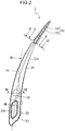
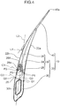
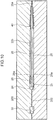
- the base portion 10 has a handle portion 20 to be held by fingers, and a shaft portion 40 connected to a distal end portion (upper end portion in FIG. 4 ) of the handle portion 20.
- the handle portion 20 has a shape curved at least partially. With regard to the present embodiment, the handle portion 20 is formed in a flat shape.
- the handle portion 20 has a handle main body 22 and a held portion 30.
- the handle main body 22 has a shape which is curved entirely.
- the handle main body 22 has a belly-side edge portion 22a and a back-side edge portion 22b.
- the belly-side edge portion 22a is a portion which is formed on one side (the right side in FIG. 4 ) of the handle main body 22 in a direction orthogonal to an axial direction of the shaft portion 40, the belly-side edge portion 22a having a curved shape.
- the back-side edge portion 22b is a portion which is formed on the other side (the left side in FIG. 4 ) of the handle main body 22 in the direction orthogonal to the axial direction of the shaft portion 40, the back-side edge portion 22b having a curved shape.
- a size of the handle main body 22 in a width direction is larger than a thickness of the handle main body 22.
- the handle main body 22 has a base 24, a recessed portion 26 and bulge portions 28.
- the base 24 includes the belly-side edge portion 22a and has a curved shape.
- the recessed portion 26 has a shape recessed from surfaces of the base 24.
- the recessed portion 26 includes the back-side edge portion 22b and has the curved shape.
- the recessed portion 26 is formed on both surfaces of the handle main body 22.
- the recessed portion 26 has a flow path widening region 26A.
- the flow path widening region 26A is a region in which a flow path area for the elastomer at a portion distant by 1 mm from a specific portion of the recessed portion 26 to the opposite side from the shaft portion 40 (downward in FIG. 4 ) is larger by no less than 7% in comparison with a flow path area for the elastomer at the specific portion.
- the flow path widening region 26A is hatched for the purpose of illustration.
- Each of the bulge portions 28 has a shape bulging from a portion of a surface of the recessed portion 26 at a distance from a boundary 25 between the base 24 and the recessed portion 26 (a side surface rising from a proximal end portion of the recessed portion 26).
- Each of the bulge portions 28 is formed at a position at which the bulge portion 28 at least partially overlaps the flow path widening region 26A of the recessed portion 26.
- a side surface 28a of each of the bulge portions 28 is formed in a shape which is gradually and slightly inclined toward a center of the bulge portion 28 as a distance from the surface of the recessed portion 26 increases.
- the held portion 30 is a part to be held by the second mold 200 in the second step.
- the held portion 30 is connected to a proximal end portion of the handle main body 22.
- a single hole 30h is formed in the held portion 30.
- the hole 30h is used by the second mold 200 to hold the held portion 30. Therefore, as compared with a case where a plurality of holes are formed in the held portion 30, strength of the second mold 200 is secured.
- the shaft portion 40 is connected to the distal end portion (upper end portion in FIG. 4 ) of the handle portion 20 and has a shape which allows the shaft portion 40 to be inserted into interdental spaces.
- the shaft portion 40 has a shape extending straight.
- the shaft portion 40 has a sectional area (an area of a section along a plane orthogonal to the axial direction of the shaft portion 40) smaller than a sectional area of the handle portion 20.
- the shaft portion 40 has a substantially circular columnar shape.
- the shaft portion 40 is formed into a shape having an outer diameter which gradually and slightly reduces from the proximal end portion toward the distal end portion.
- the shaft portion 40 is formed integrally with the handle portion 20.
- An orientation (attitude) of the shaft portion 40 with respect to the handle portion 20 is set so that an angle between a tangent to a distal end portion of the back-side edge portion 22b and the axial direction of the shaft portion 40 is smaller than an angle between a tangent to a distal end portion of the belly-side edge portion 22a and the axial direction of the shaft portion 40.
- an angle ⁇ (c.f. FIG. 4 ) between a first straight line L1 extending through the center of the shaft portion 40 and a second straight line L2 is preferably set to 10° to 50°.
- the second straight line L2 is a straight line extending through a first midpoint P3 and a second midpoint Q3.
- the first midpoint P3 is a midpoint between an intersection point P1 of a first circle C1 in a first radius (45 mm in the present embodiment), which is centered at the distal end portion 40a of the shaft portion 40, with the belly-side edge portion 22a and an intersection point P2 of the first circle C1 with the belly-side edge portion 22a.
- the second midpoint Q3 is a midpoint between an intersection point Q1 of a second circle C2 in a second radius (50 mm in the present embodiment), which is centered at the distal end portion 40a of the shaft portion 40, with the belly-side edge portion 22a and an intersection point Q2 of the second circle C2 with the back-side edge portion 22b.
- the soft portion 50 includes a cleaning portion 60 configured to clean interdental spaces, a slip resistance portion 70 and a coupling portion 80.
- the cleaning portion 60 is provided around the shaft portion 40.
- the cleaning portion 60 includes a cleaning portion main body 62 having such a shape as to cover a surface of the shaft portion 40 and brush hairs 64.
- Each of the brush hairs 64 protrudes outward in a direction orthogonal to the axial direction of the shaft portion 40 from the outer peripheral surface of the cleaning portion main body 62 and has an outer shape gradually getting smaller as a distance from the outer peripheral surface of the cleaning portion main body 62 increases.
- each of the brush hairs 64 is formed in a cone shape.
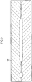
- the slip resistance portion 70 is formed on the surface of the recessed portion 26. As shown in FIGS. 7 and 8 , a surface of the slip resistance portion 70 is formed to be flush with the surface of the base 24. On the other hand, as shown in FIG. 8 , a surface of each of the bulge portions 28 protrudes by a predetermined dimension D (0.15 mm in the present embodiment) from the surface of the slip resistance portion 70 and the surface of the base 24.
- the coupling portion 80 couples the cleaning portion 60 and the slip resistance portion 70.
- the coupling portion 80 couples the cleaning portion 60 and the slip resistance portion 70 on a surface of the distal end portion of the back-side edge portion 22b of the handle main body 22.
- a sectional area of the coupling portion 80 is smaller than a sectional area of the cleaning portion main body 62 and a sectional area of the slip resistance portion 70.
- FIG. 5 shows a section of the cleaning portion 60 at the proximal end portion
- FIG. 6 shows a section of the coupling portion 80 at the distal end portion.
- an area of the elastomer at the distal end portion of the coupling portion 80 (hereinafter referred to as “coupling portion distal end portion area”) is smaller than an area of the elastomer at the proximal end portion of the cleaning portion 60 (hereinafter referred to as "cleaning portion proximal end portion area").
- a ratio of the coupling portion distal end portion area to the cleaning portion proximal end portion area is preferably between 40% and 90% (inclusive), more preferably between 50% and 85% (inclusive), and yet more preferably between 65% and 85% (inclusive). With regard to the present embodiment, the ratio is set to 70%.
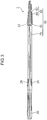
- a method for manufacturing the interdental cleaner 2 is described with reference to FIGS. 9 and 10 .
- the manufacturing method includes the first step and the second step as described above.
- the composite material material including the synthetic resin, the glass fiber and titanium dioxide
- the first mold 100 having the first space in correspondence to the base portions 10 from gates which is formed at positions in correspondence to the proximal end portions of the base portions 10.
- the base portions 10 are molded.
- the first space is a space having a shape in conformity to the base portions 10 connected to each other by the connecting portions 32.
- the second mold 200 having the spaces for forming the soft portions 50 on the base portions 10 is used.
- the base portions 10 are situated in the second mold 200 at first.
- the base portions 10 are situated in the second mold 200 so that holding portions 202 of the second mold 200 are fitted in the holes 30h in the held portions 30 and that the bulge portions 28 of the base portions 10 are fitted with inner surfaces of the second mold 200.
- each of the bulge portions 28 is guided so as to be fitted with the inner surface of the second mold 200, even if each of the bulge portions 28 is slightly biased from the position in which the bulge portion 28 is fitted with the inner surface of the second mold 200.
- the elastomer is filled into the second mold 200 in this state.
- the elastomer is injected from gates 204 formed at positions of the second mold 200 in correspondence to the distal end portions of the shaft portions 40. In this way, the elastomer flows from the peripheries of the shaft portions 40 toward the recessed portions 26.
- a ratio of the coupling portion distal end portion area (the flow path area for the elastomer around the distal end portion of the back-side edge portion 22b of each of the handle main bodies 22 in the section at the distal end portion) to the cleaning portion proximal end portion area (the flow path area for the elastomer around the proximal end portion of each of the shaft portions 40 in the section of the proximal end portion) is set to 70%, so that an excessively large pressure loss is suppressed when the elastomer flowing along each of the shaft portions 40 flows through a space in correspondence to each of the coupling portions 80.
- the elastomer flows smoothly from the space around each of the shaft portions 40 toward the space in correspondence to each of the slip resistance portions 70 through the space in correspondence to each of the coupling portions 80. In this way, it is suppressed for the elastomer to leak from the second spaces in the second step. Since the ratio is set to 70%, pressure loss is secured to some extent when the elastomer flows through the space in correspondence to each of the coupling portions 80. In this way, the elastomer is filled into the spaces in correspondence to the respective brush hairs 64, so that it is suppressed that incomplete molding happens to each of the cleaning portions 60.
- the elastomer collides with the side surface 28a of each of the bulge portions 28 before colliding with the boundary 25 between the base 24 and the recessed portion 26 (the side surface rising from the proximal end portion of the recessed portion 26). At this time, a flow velocity of the elastomer reduces. Then, the elastomer colliding with the side surface 28a of each of the bulge portions 28 flows around the bulge portion 28 and reaches the boundary 25. In this way, the elastomer is prevented from strongly colliding with the boundary 25 between the recessed portion 26 and the base 24. As a result, in the second step, it is suppressed for the elastomer to leak from the second spaces in the second mold 200 to the outside of the second spaces.
- the interdental cleaner group 1 including the interdental cleaners 2 is formed.
- the interdental cleaner group 1 it is possible to check insufficient filling (short shot) of the elastomer near the bulge portions 28 by taking an image of the interdental cleaner group 1.
- each of the bulge portions 28 is formed as a floating structure in the slip resistance portion 70 made of the elastomer, it is possible to check insufficient filling by checking whether the elastomer is filled appropriately to surround each of the bulge portions 28.
- each of the shaft portions 40 and each of the handle main portions 22 are slightly displaced toward each of the belly-side edge portions 22a due to an injection pressure of the elastomer while each of the holding portions 202 works as a fulcrum when the elastomer flows along each of the back-side edge portions 22b in the second step, the space for forming each of the coupling portions 80 (the flow path area for the elastomer) is secured. As a result, the elastomer smoothly flows toward each of the recessed portions 26.
- each of the base portions 10 is molded in the first step to have a smaller angle between the tangent to the distal end portion of the back-side edge portion 22b and the axial direction of the shaft portion 40 than an angle between the tangent to the distal end portion of the belly-side edge portion 22a and the axial direction of the shaft portion 40, the elastomer further smoothly flows from the periphery of each of the shaft portions 40 toward each of the recessed portions 26 in the second step.
- each of the bulge portions 28 Since a part of each of the bulge portions 28 is situated in each of the flow path widening regions 26A, it is possible to manufacture the interdental cleaners 2 having effective slip resistance functions of the slip resistance portions 70 with suppressing jetting near each of the flow path widening regions 26A when the elastomer flows along each of the recessed portions 26 in the second step.
- the jetting may occur near the position of the abrupt increase in the flow path area.
- each of the bulge portions 28 is at least partially situated in each of the flow path widening regions 26A, the jetting resultant from the increase in the flow path area is suppressed.
- the base portions 10 reinforced with the glass fiber are molded. As a result, it is possible to suppress damage to the bulge portions 28 even if there is a contact between the bulge portions 28 and the second mold 200 when the base portions 10 are situated in the second mold 200. Vibration of the base portions 10 may be suppressed as well when the base portions 10 are situated in the second mold 200.
- the composite material further includes titanium dioxide.
- the reinforcing effect of the glass fiber on the base portions 10 is slightly reduced by the inclusion of titanium dioxide, the bulge portions 28 provided to the base portions 10 suppress the reduction in strength of the handle portions 20 caused by the inclusion of titanium dioxide and the resultant vibration of the base portions 10 in positioning of the base portions 10 in the second mold 200. It is possible to mold the white base portions 10 at low cost. It is preferable from a viewpoint of suppressing the reduction in strength that material used to obtain the white base portions 10 is zinc sulfide.
- the handle portion 20 Since the base 24 extends continuously along the belly-side edge portion 22a, the handle portion 20 has higher strength as compared to a case in which a part of the slip resistance portion 70 made of the elastomer is provided along the belly-side edge portion 22a, for example.
- injecting positions of the elastomer in the second step i.e., the positions of the gates 204 are not restricted to those in the aforementioned example.
- the gates 204 may be provided at positions in correspondence to portions of the base portions 10 between the shaft portions 40 and the bulge portions 28. In this way, the elastomer flowing along each of the recessed portions 26 becomes likely to collide with the side surface 28a of each of the bulge portions 28. As a result, so-called jetting is suppressed near each of the bulge portions 28.
- the recessed portion 26 and the slip resistance portion 70 may be provided to only one surface of the handle main body 22.
- a mold which has a lower mold including a base mold and a rotatable mold and an upper mold for forming a first space and a second space with the lower mold, may be used as the first mold 100 and the second mold 200.
- the rotatable mold is a mold which is rotatable with respect to the base mold while holding the held portion 30 of the base portion 10.
- the base mold has portions configured to form a space in correspondence to the handle main body 22 and the shaft portion 40, and a space in correspondence to the soft portion 50.
- the rotatable mold has a portion configured to form a space in correspondence to the held portion 30.
- composite material is filled into the first space formed between the lower mold and the upper mold in the first step.
- the upper mold is separated from the lower mold upward, and the rotatable mold is separated from the base mold upward while holding the held portion 30 and rotates 180° in the position, and then is displaced toward the base mold again.
- the base portion 10 is situated in the space in the lower mold, the space being in correspondence to the soft portion 50 (the region below the second space).
- the upper mold comes into contact with the lower mold to form the first space and the second space.
- elastomer is filled into the second space.
- the composite material is filled into the first space (the first step is performed).
- the coupling portions 80 may not be provided.
- the second mold 200 is provided with gates for forming the cleaning portions 60 and gates for forming the slip resistance portions 70. The elastomer is injected from the respective gates.
Landscapes
- Engineering & Computer Science (AREA)
- Manufacturing & Machinery (AREA)
- Health & Medical Sciences (AREA)
- Mechanical Engineering (AREA)
- Chemical & Material Sciences (AREA)
- Materials Engineering (AREA)
- Dentistry (AREA)
- Epidemiology (AREA)
- Life Sciences & Earth Sciences (AREA)
- Animal Behavior & Ethology (AREA)
- General Health & Medical Sciences (AREA)
- Public Health (AREA)
- Veterinary Medicine (AREA)
- Moulds For Moulding Plastics Or The Like (AREA)
- Injection Moulding Of Plastics Or The Like (AREA)
Claims (7)
- Verfahren zum Herstellen eines Zwischenzahnreinigers (2), wobei das Verfahren umfasst:einen ersten Schritt des Formens eines Basisabschnitts (24) durch Einfüllen von Verbundmaterial, das Kunstharz einschließt, in eine erste Form (100), die einen ersten Raum gemäß dem Basisabschnitt aufweist, einschließlich eines Griffabschnitts (20), der eine Form aufweist, die mindestens teilweise gekrümmt ist, und eines Schaftabschnitts (40), der mit einem distalen Endabschnitt des Griffabschnitts verbunden ist, wobei der Schaftabschnitt eine Querschnittsfläche, die kleiner ist als eine Querschnittsfläche des Griffabschnitts, und eine Form, die es ermöglicht, dass der Schaftabschnitt in einen Zahnzwischenraum eingeführt werden kann, aufweist; undeinen zweiten Schritt des Bildens eines Reinigungsabschnitts (60), der so konfiguriert ist, dass er den Zahnzwischenraum reinigt, und eines Gleitwiderstandsabschnitts (70) durch Einfüllen von Elastomer in eine zweite Form (200) unter einer Bedingung, in der sich der Basisabschnitt in der zweiten Form befindet, wobei die zweite Form einen zweiten Raum einschließt, der so konfiguriert ist, dass er den Reinigungsabschnitt um den Schaftabschnitt herum bildet und den Gleitwiderstandsabschnitt auf einer Oberfläche des Griffabschnitts bildet,wobei im ersten Schritt das, was als der Griffabschnitt geformt wird, eine Basis (10), einen ausgesparten Abschnitt (26), der eine von einer Oberfläche der Basis ausgesparte Form aufweist, und einen Aufwölbungsabschnitt (28), der sich von einem Abschnitt einer Oberfläche des ausgesparten Abschnitts wölbt, der von einer Grenze zwischen der Basis und dem ausgesparten Abschnitt entfernt ist, einschließt, undwobei im zweiten Schritt der Reinigungsabschnitt um den Schaftabschnitt herum gebildet wird und der Gleitwiderstandsabschnitt auf der Oberfläche des ausgesparten Abschnitts durch Einfüllen des Elastomers in den zweiten Raum von einem Abschnitt des Basisabschnitts aus gebildet wird, der näher am Schaftabschnitt liegt als der Aufwölbungsabschnitt, so dass das Elastomer entlang des Schaftabschnitts und des ausgesparten Abschnitts fließt.
- Verfahren zum Herstellen eines Zwischenzahnreinigers nach Anspruch 1,
wobei im zweiten Schritt das Elastomer von einer Position aus, die einem distalen Endabschnitt des Schaftabschnitts entspricht, in den zweiten Raum eingefüllt wird. - Verfahren zum Herstellen eines Zwischenzahnreinigers nach Anspruch 1,
wobei im zweiten Schritt das Elastomer von einem Abschnitt des ausgesparten Abschnitts, der näher am Schaftabschnitt liegt als der Aufwölbungsabschnitt, in den zweiten Raum eingefüllt wird. - Verfahren zum Herstellen eines Zwischenzahnreinigers nach Anspruch 2,
wobei im ersten Schritt das, was als der Griffabschnitt geformt wird, einen rückseitigen Kantenabschnitt (22b), der auf einer Seite in einer Richtung orthogonal zu einer axialen Richtung des Schaftabschnitts gebildet ist, um eine gekrümmte Form aufzuweisen, einen bauchseitigen Kantenabschnitt (22a), der auf einer anderen Seite gebildet ist, um eine gekrümmte Form aufzuweisen, wobei die Basis an einer Position gebildet ist, die mindestens einen Teil des bauchseitigen Kantenabschnitts einschließt, wobei der ausgesparte Abschnitt an einer Position gebildet ist, die mindestens einen Teil des rückseitigen Kantenabschnitts einschließt, und einen Winkel zwischen einer Tangente an einen distalen Endabschnitt des rückseitigen Kantenabschnitts und der axialen Richtung des Schaftabschnitts, wobei der Winkel kleiner ist als ein Winkel zwischen einer Tangente an einen distalen Endabschnitt des bauchseitigen Kantenabschnitts und der axialen Richtung des Schaftabschnitts, aufweist. - Verfahren zum Herstellen eines Zwischenzahnreinigers nach Anspruch 2 oder 4, wobei im ersten Schritt das, was geformt wird, den ausgesparten Abschnitt, einschließlich eines Fließwegverbreiterungsbereichs (26A), in dem eine Fließwegfläche für das Elastomer an einem Abschnitt, der um 1 mm von einem bestimmten Abschnitt des ausgesparten Abschnitts zu einer gegenüberliegenden Seite des Schaftabschnitts entfernt ist, um nicht weniger als 7 % im Vergleich zu einer Fließwegfläche für das Elastomer an dem bestimmten Abschnitt größer ist, und den Aufwölbungsabschnitt, der mindestens teilweise in dem Fließwegverbreiterungsbereich liegt, aufweist.
- Verfahren zum Herstellen eines Zwischenzahnreinigers nach einem der Ansprüche 1 bis 5,
wobei im ersten Schritt das Verbundmaterial, das das Kunstharz und die Glasfaser einschließt, in die erste Form eingefüllt wird. - Verfahren zum Herstellen eines Zwischenzahnreinigers nach Anspruch 6,
wobei im ersten Schritt das Verbundmaterial, das weiter Titandioxid einschließt, in die erste Form eingefüllt wird.
Applications Claiming Priority (2)
| Application Number | Priority Date | Filing Date | Title |
|---|---|---|---|
| JP2016256516A JP6387386B2 (ja) | 2016-12-28 | 2016-12-28 | 歯間清掃具の製造方法 |
| PCT/JP2017/047351 WO2018124298A1 (ja) | 2016-12-28 | 2017-12-28 | 歯間清掃具の製造方法 |
Publications (3)
| Publication Number | Publication Date |
|---|---|
| EP3563797A1 EP3563797A1 (de) | 2019-11-06 |
| EP3563797A4 EP3563797A4 (de) | 2020-09-02 |
| EP3563797B1 true EP3563797B1 (de) | 2021-10-20 |
Family
ID=62709508
Family Applications (1)
| Application Number | Title | Priority Date | Filing Date |
|---|---|---|---|
| EP17888778.2A Active EP3563797B1 (de) | 2016-12-28 | 2017-12-28 | Verfahren zur herstellung eines zahnzwischenraumreinigers |
Country Status (5)
| Country | Link |
|---|---|
| US (1) | US11358312B2 (de) |
| EP (1) | EP3563797B1 (de) |
| JP (1) | JP6387386B2 (de) |
| CN (1) | CN110121309B (de) |
| WO (1) | WO2018124298A1 (de) |
Families Citing this family (11)
| Publication number | Priority date | Publication date | Assignee | Title |
|---|---|---|---|---|
| JP6752139B2 (ja) * | 2016-12-28 | 2020-09-09 | 小林製薬株式会社 | 歯間清掃具の製造方法 |
| JP6387386B2 (ja) * | 2016-12-28 | 2018-09-05 | 小林製薬株式会社 | 歯間清掃具の製造方法 |
| JP2018108483A (ja) * | 2018-03-29 | 2018-07-12 | 小林製薬株式会社 | 歯間清掃具の製造方法 |
| JP7652528B2 (ja) | 2018-12-28 | 2025-03-27 | 小林製薬株式会社 | 歯間清掃具 |
| JP2020103851A (ja) | 2018-12-28 | 2020-07-09 | 小林製薬株式会社 | 歯間清掃具 |
| JP7417353B2 (ja) * | 2018-12-28 | 2024-01-18 | 小林製薬株式会社 | 歯間清掃具の製造方法 |
| JP1661180S (de) * | 2019-09-27 | 2020-06-08 | ||
| JP1661181S (de) * | 2019-09-27 | 2020-06-08 | ||
| JP1661179S (de) * | 2019-09-27 | 2020-06-08 | ||
| JP7457502B2 (ja) * | 2019-12-27 | 2024-03-28 | 小林製薬株式会社 | 歯間清掃具 |
| JP7378294B2 (ja) * | 2019-12-27 | 2023-11-13 | 小林製薬株式会社 | 歯間清掃具 |
Family Cites Families (20)
| Publication number | Priority date | Publication date | Assignee | Title |
|---|---|---|---|---|
| FR2519543A1 (fr) | 1982-01-08 | 1983-07-18 | Benhamou Leon | Cure-dents |
| DE19857296A1 (de) * | 1998-12-14 | 2000-06-15 | Hauni Maschinenbau Ag | Verfahren und Vorrichtung zum Bilden eines Tabakstrangs |
| US6397425B1 (en) | 1999-08-31 | 2002-06-04 | Gillette Canada Company | Polypropylene brush body |
| DE10033256A1 (de) * | 2000-07-10 | 2002-01-24 | Coronet Werke Gmbh | Verfahren und Vorrichtung zur Herstellung von Borstenwaren sowie Borstenware |
| DE10065517A1 (de) * | 2000-12-28 | 2002-07-04 | Trisa Holding Ag Triengen | Verfahren zur Herstellung einer Zahnbürste |
| US6973932B2 (en) * | 2002-09-23 | 2005-12-13 | Wei-Chu Ko | Toothpick and interdental brush combination |
| EP1643930A1 (de) | 2003-07-15 | 2006-04-12 | Braun GmbH | Elektrisches gerät zum reinigen von zahnzwischenräumen sowie zum behandeln von zähnen oder zahnfleisch und werkzeuge hierzu |
| CN101138524A (zh) | 2007-09-28 | 2008-03-12 | 林燕 | 一种多功能保健牙签 |
| US20130273502A1 (en) * | 2008-03-24 | 2013-10-17 | Richard J. Shaw | Dental probe, a method of forming the probe and a method of using the probe |
| US9468510B2 (en) * | 2008-03-24 | 2016-10-18 | Richard J. Shaw | Floss device, a method of forming the floss device and a method of using the floss device |
| JP5836610B2 (ja) * | 2011-03-04 | 2015-12-24 | キヤノン株式会社 | プラスチック光学部材及びその製造方法 |
| EP2857167B1 (de) | 2012-05-24 | 2023-03-15 | Sunstar Suisse SA | Verfahren zur herstellung eines interdentalen reinigungswerkzeugs und interdentales reinigungswerkzeug |
| ES2605394T3 (es) * | 2014-03-06 | 2017-03-14 | Tepe Munhygienprodukter Ab | Limpiador interdental |
| CN107106272B (zh) * | 2014-11-11 | 2019-06-14 | 盛势达(瑞士)有限公司 | 牙缝清洁工具的制造方法 |
| EP3305243B1 (de) | 2015-06-08 | 2024-12-11 | Sunstar Suisse SA | Interdentalreinigungswerkzeug |
| JP6625374B2 (ja) * | 2015-08-28 | 2019-12-25 | 小林製薬株式会社 | 歯間清掃具及び歯間清掃具の製造方法 |
| JP6639875B2 (ja) * | 2015-11-17 | 2020-02-05 | 小林製薬株式会社 | 歯間清掃具 |
| JP6730797B2 (ja) * | 2015-11-17 | 2020-07-29 | 小林製薬株式会社 | 歯間清掃具群 |
| JP6292246B2 (ja) * | 2016-03-07 | 2018-03-14 | サンスター株式会社 | 歯間清掃具 |
| JP6387386B2 (ja) * | 2016-12-28 | 2018-09-05 | 小林製薬株式会社 | 歯間清掃具の製造方法 |
-
2016
- 2016-12-28 JP JP2016256516A patent/JP6387386B2/ja active Active
-
2017
- 2017-12-28 WO PCT/JP2017/047351 patent/WO2018124298A1/ja not_active Ceased
- 2017-12-28 EP EP17888778.2A patent/EP3563797B1/de active Active
- 2017-12-28 US US16/472,873 patent/US11358312B2/en active Active
- 2017-12-28 CN CN201780081355.XA patent/CN110121309B/zh not_active Expired - Fee Related
Also Published As
| Publication number | Publication date |
|---|---|
| CN110121309A (zh) | 2019-08-13 |
| EP3563797A4 (de) | 2020-09-02 |
| US11358312B2 (en) | 2022-06-14 |
| CN110121309B (zh) | 2021-08-13 |
| WO2018124298A1 (ja) | 2018-07-05 |
| JP2018108147A (ja) | 2018-07-12 |
| US20200188071A1 (en) | 2020-06-18 |
| EP3563797A1 (de) | 2019-11-06 |
| JP6387386B2 (ja) | 2018-09-05 |
Similar Documents
| Publication | Publication Date | Title |
|---|---|---|
| EP3563797B1 (de) | Verfahren zur herstellung eines zahnzwischenraumreinigers | |
| EP3563798B1 (de) | Verfahren zur herstellung eines interdentalreinigungsinstruments | |
| JP6262288B2 (ja) | 歯間清掃具の製造方法 | |
| US10918466B2 (en) | Base portion, inter-dental cleaning tool, and method of manufacturing inter-dental cleaning tool | |
| JP2017000762A (ja) | 歯間清掃具の製造方法 | |
| US20120118850A1 (en) | Multilayered cosmetic container | |
| US8408891B2 (en) | Golf ball mold and golf ball manufacturing method | |
| KR102629317B1 (ko) | 전체 두께 리브 섹션을 갖는 가요성 골프 그립 및 그의 제조 방법 | |
| US11633269B2 (en) | Method of manufacturing inter-dental cleaning tool | |
| EP3785663B1 (de) | Interdentalreinigungswerkzeug | |
| JP4929245B2 (ja) | 工具類のグリップ | |
| JP2018108483A (ja) | 歯間清掃具の製造方法 | |
| HK40006294A (zh) | 齿间清洁具的制造方法 | |
| HK40006295A (en) | Method for producing interdental cleaning tool | |
| HK40006295B (en) | Method for producing interdental cleaning tool | |
| HK40006294B (zh) | 齿间清洁具的制造方法 | |
| JP7105124B2 (ja) | 二色成形物の製造方法および二色成形物 | |
| US12442415B2 (en) | Cage and ball bearing | |
| JP3956123B2 (ja) | コネクターシール | |
| EP3858573B1 (de) | Thermoplastischer elastomerer balgkanal | |
| JPS60161123A (ja) | 筒状厚肉樹脂成形品の射出成形用金型 | |
| JP2001080279A (ja) | 替え芯ケース | |
| KR101268384B1 (ko) | 강도보강용 선 부재가 인서트사출된 곡선형 수지체 | |
| CN118871010A (zh) | 牙刷 |
Legal Events
| Date | Code | Title | Description |
|---|---|---|---|
| STAA | Information on the status of an ep patent application or granted ep patent |
Free format text: STATUS: THE INTERNATIONAL PUBLICATION HAS BEEN MADE |
|
| PUAI | Public reference made under article 153(3) epc to a published international application that has entered the european phase |
Free format text: ORIGINAL CODE: 0009012 |
|
| STAA | Information on the status of an ep patent application or granted ep patent |
Free format text: STATUS: REQUEST FOR EXAMINATION WAS MADE |
|
| 17P | Request for examination filed |
Effective date: 20190628 |
|
| AK | Designated contracting states |
Kind code of ref document: A1 Designated state(s): AL AT BE BG CH CY CZ DE DK EE ES FI FR GB GR HR HU IE IS IT LI LT LU LV MC MK MT NL NO PL PT RO RS SE SI SK SM TR |
|
| AX | Request for extension of the european patent |
Extension state: BA ME |
|
| DAV | Request for validation of the european patent (deleted) | ||
| DAX | Request for extension of the european patent (deleted) | ||
| A4 | Supplementary search report drawn up and despatched |
Effective date: 20200803 |
|
| RIC1 | Information provided on ipc code assigned before grant |
Ipc: A61C 15/02 20060101AFI20200728BHEP |
|
| GRAP | Despatch of communication of intention to grant a patent |
Free format text: ORIGINAL CODE: EPIDOSNIGR1 |
|
| STAA | Information on the status of an ep patent application or granted ep patent |
Free format text: STATUS: GRANT OF PATENT IS INTENDED |
|
| INTG | Intention to grant announced |
Effective date: 20210503 |
|
| GRAS | Grant fee paid |
Free format text: ORIGINAL CODE: EPIDOSNIGR3 |
|
| GRAA | (expected) grant |
Free format text: ORIGINAL CODE: 0009210 |
|
| STAA | Information on the status of an ep patent application or granted ep patent |
Free format text: STATUS: THE PATENT HAS BEEN GRANTED |
|
| AK | Designated contracting states |
Kind code of ref document: B1 Designated state(s): AL AT BE BG CH CY CZ DE DK EE ES FI FR GB GR HR HU IE IS IT LI LT LU LV MC MK MT NL NO PL PT RO RS SE SI SK SM TR |
|
| REG | Reference to a national code |
Ref country code: GB Ref legal event code: FG4D |
|
| REG | Reference to a national code |
Ref country code: CH Ref legal event code: EP |
|
| REG | Reference to a national code |
Ref country code: IE Ref legal event code: FG4D |
|
| REG | Reference to a national code |
Ref country code: DE Ref legal event code: R096 Ref document number: 602017048090 Country of ref document: DE |
|
| REG | Reference to a national code |
Ref country code: AT Ref legal event code: REF Ref document number: 1439287 Country of ref document: AT Kind code of ref document: T Effective date: 20211115 |
|
| REG | Reference to a national code |
Ref country code: LT Ref legal event code: MG9D |
|
| REG | Reference to a national code |
Ref country code: NL Ref legal event code: MP Effective date: 20211020 |
|
| REG | Reference to a national code |
Ref country code: AT Ref legal event code: MK05 Ref document number: 1439287 Country of ref document: AT Kind code of ref document: T Effective date: 20211020 |
|
| PG25 | Lapsed in a contracting state [announced via postgrant information from national office to epo] |
Ref country code: RS Free format text: LAPSE BECAUSE OF FAILURE TO SUBMIT A TRANSLATION OF THE DESCRIPTION OR TO PAY THE FEE WITHIN THE PRESCRIBED TIME-LIMIT Effective date: 20211020 Ref country code: LT Free format text: LAPSE BECAUSE OF FAILURE TO SUBMIT A TRANSLATION OF THE DESCRIPTION OR TO PAY THE FEE WITHIN THE PRESCRIBED TIME-LIMIT Effective date: 20211020 Ref country code: FI Free format text: LAPSE BECAUSE OF FAILURE TO SUBMIT A TRANSLATION OF THE DESCRIPTION OR TO PAY THE FEE WITHIN THE PRESCRIBED TIME-LIMIT Effective date: 20211020 Ref country code: BG Free format text: LAPSE BECAUSE OF FAILURE TO SUBMIT A TRANSLATION OF THE DESCRIPTION OR TO PAY THE FEE WITHIN THE PRESCRIBED TIME-LIMIT Effective date: 20220120 Ref country code: AT Free format text: LAPSE BECAUSE OF FAILURE TO SUBMIT A TRANSLATION OF THE DESCRIPTION OR TO PAY THE FEE WITHIN THE PRESCRIBED TIME-LIMIT Effective date: 20211020 |
|
| PG25 | Lapsed in a contracting state [announced via postgrant information from national office to epo] |
Ref country code: IS Free format text: LAPSE BECAUSE OF FAILURE TO SUBMIT A TRANSLATION OF THE DESCRIPTION OR TO PAY THE FEE WITHIN THE PRESCRIBED TIME-LIMIT Effective date: 20220220 Ref country code: SE Free format text: LAPSE BECAUSE OF FAILURE TO SUBMIT A TRANSLATION OF THE DESCRIPTION OR TO PAY THE FEE WITHIN THE PRESCRIBED TIME-LIMIT Effective date: 20211020 Ref country code: PT Free format text: LAPSE BECAUSE OF FAILURE TO SUBMIT A TRANSLATION OF THE DESCRIPTION OR TO PAY THE FEE WITHIN THE PRESCRIBED TIME-LIMIT Effective date: 20220221 Ref country code: PL Free format text: LAPSE BECAUSE OF FAILURE TO SUBMIT A TRANSLATION OF THE DESCRIPTION OR TO PAY THE FEE WITHIN THE PRESCRIBED TIME-LIMIT Effective date: 20211020 Ref country code: NO Free format text: LAPSE BECAUSE OF FAILURE TO SUBMIT A TRANSLATION OF THE DESCRIPTION OR TO PAY THE FEE WITHIN THE PRESCRIBED TIME-LIMIT Effective date: 20220120 Ref country code: NL Free format text: LAPSE BECAUSE OF FAILURE TO SUBMIT A TRANSLATION OF THE DESCRIPTION OR TO PAY THE FEE WITHIN THE PRESCRIBED TIME-LIMIT Effective date: 20211020 Ref country code: LV Free format text: LAPSE BECAUSE OF FAILURE TO SUBMIT A TRANSLATION OF THE DESCRIPTION OR TO PAY THE FEE WITHIN THE PRESCRIBED TIME-LIMIT Effective date: 20211020 Ref country code: HR Free format text: LAPSE BECAUSE OF FAILURE TO SUBMIT A TRANSLATION OF THE DESCRIPTION OR TO PAY THE FEE WITHIN THE PRESCRIBED TIME-LIMIT Effective date: 20211020 Ref country code: GR Free format text: LAPSE BECAUSE OF FAILURE TO SUBMIT A TRANSLATION OF THE DESCRIPTION OR TO PAY THE FEE WITHIN THE PRESCRIBED TIME-LIMIT Effective date: 20220121 Ref country code: ES Free format text: LAPSE BECAUSE OF FAILURE TO SUBMIT A TRANSLATION OF THE DESCRIPTION OR TO PAY THE FEE WITHIN THE PRESCRIBED TIME-LIMIT Effective date: 20211020 |
|
| REG | Reference to a national code |
Ref country code: DE Ref legal event code: R097 Ref document number: 602017048090 Country of ref document: DE |
|
| PG25 | Lapsed in a contracting state [announced via postgrant information from national office to epo] |
Ref country code: SM Free format text: LAPSE BECAUSE OF FAILURE TO SUBMIT A TRANSLATION OF THE DESCRIPTION OR TO PAY THE FEE WITHIN THE PRESCRIBED TIME-LIMIT Effective date: 20211020 Ref country code: SK Free format text: LAPSE BECAUSE OF FAILURE TO SUBMIT A TRANSLATION OF THE DESCRIPTION OR TO PAY THE FEE WITHIN THE PRESCRIBED TIME-LIMIT Effective date: 20211020 Ref country code: RO Free format text: LAPSE BECAUSE OF FAILURE TO SUBMIT A TRANSLATION OF THE DESCRIPTION OR TO PAY THE FEE WITHIN THE PRESCRIBED TIME-LIMIT Effective date: 20211020 Ref country code: MC Free format text: LAPSE BECAUSE OF FAILURE TO SUBMIT A TRANSLATION OF THE DESCRIPTION OR TO PAY THE FEE WITHIN THE PRESCRIBED TIME-LIMIT Effective date: 20211020 Ref country code: EE Free format text: LAPSE BECAUSE OF FAILURE TO SUBMIT A TRANSLATION OF THE DESCRIPTION OR TO PAY THE FEE WITHIN THE PRESCRIBED TIME-LIMIT Effective date: 20211020 Ref country code: DK Free format text: LAPSE BECAUSE OF FAILURE TO SUBMIT A TRANSLATION OF THE DESCRIPTION OR TO PAY THE FEE WITHIN THE PRESCRIBED TIME-LIMIT Effective date: 20211020 Ref country code: CZ Free format text: LAPSE BECAUSE OF FAILURE TO SUBMIT A TRANSLATION OF THE DESCRIPTION OR TO PAY THE FEE WITHIN THE PRESCRIBED TIME-LIMIT Effective date: 20211020 |
|
| PLBE | No opposition filed within time limit |
Free format text: ORIGINAL CODE: 0009261 |
|
| STAA | Information on the status of an ep patent application or granted ep patent |
Free format text: STATUS: NO OPPOSITION FILED WITHIN TIME LIMIT |
|
| REG | Reference to a national code |
Ref country code: BE Ref legal event code: MM Effective date: 20211231 |
|
| 26N | No opposition filed |
Effective date: 20220721 |
|
| GBPC | Gb: european patent ceased through non-payment of renewal fee |
Effective date: 20220120 |
|
| PG25 | Lapsed in a contracting state [announced via postgrant information from national office to epo] |
Ref country code: LU Free format text: LAPSE BECAUSE OF NON-PAYMENT OF DUE FEES Effective date: 20211228 Ref country code: IE Free format text: LAPSE BECAUSE OF NON-PAYMENT OF DUE FEES Effective date: 20211228 Ref country code: GB Free format text: LAPSE BECAUSE OF NON-PAYMENT OF DUE FEES Effective date: 20220120 Ref country code: AL Free format text: LAPSE BECAUSE OF FAILURE TO SUBMIT A TRANSLATION OF THE DESCRIPTION OR TO PAY THE FEE WITHIN THE PRESCRIBED TIME-LIMIT Effective date: 20211020 |
|
| PG25 | Lapsed in a contracting state [announced via postgrant information from national office to epo] |
Ref country code: SI Free format text: LAPSE BECAUSE OF FAILURE TO SUBMIT A TRANSLATION OF THE DESCRIPTION OR TO PAY THE FEE WITHIN THE PRESCRIBED TIME-LIMIT Effective date: 20211020 Ref country code: BE Free format text: LAPSE BECAUSE OF NON-PAYMENT OF DUE FEES Effective date: 20211231 |
|
| PG25 | Lapsed in a contracting state [announced via postgrant information from national office to epo] |
Ref country code: IT Free format text: LAPSE BECAUSE OF FAILURE TO SUBMIT A TRANSLATION OF THE DESCRIPTION OR TO PAY THE FEE WITHIN THE PRESCRIBED TIME-LIMIT Effective date: 20211020 |
|
| P01 | Opt-out of the competence of the unified patent court (upc) registered |
Effective date: 20230511 |
|
| PG25 | Lapsed in a contracting state [announced via postgrant information from national office to epo] |
Ref country code: CY Free format text: LAPSE BECAUSE OF FAILURE TO SUBMIT A TRANSLATION OF THE DESCRIPTION OR TO PAY THE FEE WITHIN THE PRESCRIBED TIME-LIMIT Effective date: 20211020 |
|
| PG25 | Lapsed in a contracting state [announced via postgrant information from national office to epo] |
Ref country code: HU Free format text: LAPSE BECAUSE OF FAILURE TO SUBMIT A TRANSLATION OF THE DESCRIPTION OR TO PAY THE FEE WITHIN THE PRESCRIBED TIME-LIMIT; INVALID AB INITIO Effective date: 20171228 |
|
| PG25 | Lapsed in a contracting state [announced via postgrant information from national office to epo] |
Ref country code: MK Free format text: LAPSE BECAUSE OF FAILURE TO SUBMIT A TRANSLATION OF THE DESCRIPTION OR TO PAY THE FEE WITHIN THE PRESCRIBED TIME-LIMIT Effective date: 20211020 |
|
| PG25 | Lapsed in a contracting state [announced via postgrant information from national office to epo] |
Ref country code: TR Free format text: LAPSE BECAUSE OF FAILURE TO SUBMIT A TRANSLATION OF THE DESCRIPTION OR TO PAY THE FEE WITHIN THE PRESCRIBED TIME-LIMIT Effective date: 20211020 |
|
| PG25 | Lapsed in a contracting state [announced via postgrant information from national office to epo] |
Ref country code: MT Free format text: LAPSE BECAUSE OF FAILURE TO SUBMIT A TRANSLATION OF THE DESCRIPTION OR TO PAY THE FEE WITHIN THE PRESCRIBED TIME-LIMIT Effective date: 20211020 |
|
| PGFP | Annual fee paid to national office [announced via postgrant information from national office to epo] |
Ref country code: CH Payment date: 20250101 Year of fee payment: 8 |
|
| REG | Reference to a national code |
Ref country code: CH Ref legal event code: U11 Free format text: ST27 STATUS EVENT CODE: U-0-0-U10-U11 (AS PROVIDED BY THE NATIONAL OFFICE) Effective date: 20260101 |
|
| PGFP | Annual fee paid to national office [announced via postgrant information from national office to epo] |
Ref country code: DE Payment date: 20251211 Year of fee payment: 9 |
|
| PGFP | Annual fee paid to national office [announced via postgrant information from national office to epo] |
Ref country code: FR Payment date: 20251229 Year of fee payment: 9 |