EP3560381B1 - Elastischer wippenartiger kippmechanismus und drehstuhl damit - Google Patents
Elastischer wippenartiger kippmechanismus und drehstuhl damit Download PDFInfo
- Publication number
- EP3560381B1 EP3560381B1 EP19159530.5A EP19159530A EP3560381B1 EP 3560381 B1 EP3560381 B1 EP 3560381B1 EP 19159530 A EP19159530 A EP 19159530A EP 3560381 B1 EP3560381 B1 EP 3560381B1
- Authority
- EP
- European Patent Office
- Prior art keywords
- support
- backrest
- locking member
- elastic
- seat
- Prior art date
- Legal status (The legal status is an assumption and is not a legal conclusion. Google has not performed a legal analysis and makes no representation as to the accuracy of the status listed.)
- Active
Links
Images





Classifications
-
- A—HUMAN NECESSITIES
- A47—FURNITURE; DOMESTIC ARTICLES OR APPLIANCES; COFFEE MILLS; SPICE MILLS; SUCTION CLEANERS IN GENERAL
- A47C—CHAIRS; SOFAS; BEDS
- A47C1/00—Chairs adapted for special purposes
- A47C1/02—Reclining or easy chairs
- A47C1/031—Reclining or easy chairs having coupled concurrently adjustable supporting parts
- A47C1/032—Reclining or easy chairs having coupled concurrently adjustable supporting parts the parts being movably-coupled seat and back-rest
- A47C1/03261—Reclining or easy chairs having coupled concurrently adjustable supporting parts the parts being movably-coupled seat and back-rest characterised by elastic means
- A47C1/03272—Reclining or easy chairs having coupled concurrently adjustable supporting parts the parts being movably-coupled seat and back-rest characterised by elastic means with coil springs
- A47C1/03274—Reclining or easy chairs having coupled concurrently adjustable supporting parts the parts being movably-coupled seat and back-rest characterised by elastic means with coil springs of torsion type
-
- A—HUMAN NECESSITIES
- A47—FURNITURE; DOMESTIC ARTICLES OR APPLIANCES; COFFEE MILLS; SPICE MILLS; SUCTION CLEANERS IN GENERAL
- A47C—CHAIRS; SOFAS; BEDS
- A47C1/00—Chairs adapted for special purposes
- A47C1/02—Reclining or easy chairs
- A47C1/031—Reclining or easy chairs having coupled concurrently adjustable supporting parts
- A47C1/032—Reclining or easy chairs having coupled concurrently adjustable supporting parts the parts being movably-coupled seat and back-rest
- A47C1/03205—Reclining or easy chairs having coupled concurrently adjustable supporting parts the parts being movably-coupled seat and back-rest having adjustable and lockable inclination
- A47C1/0325—Reclining or easy chairs having coupled concurrently adjustable supporting parts the parts being movably-coupled seat and back-rest having adjustable and lockable inclination by means of clamps or friction locking members
-
- A—HUMAN NECESSITIES
- A47—FURNITURE; DOMESTIC ARTICLES OR APPLIANCES; COFFEE MILLS; SPICE MILLS; SUCTION CLEANERS IN GENERAL
- A47C—CHAIRS; SOFAS; BEDS
- A47C1/00—Chairs adapted for special purposes
- A47C1/02—Reclining or easy chairs
- A47C1/022—Reclining or easy chairs having independently-adjustable supporting parts
- A47C1/024—Reclining or easy chairs having independently-adjustable supporting parts the parts, being the back-rest, or the back-rest and seat unit, having adjustable inclination
-
- A—HUMAN NECESSITIES
- A47—FURNITURE; DOMESTIC ARTICLES OR APPLIANCES; COFFEE MILLS; SPICE MILLS; SUCTION CLEANERS IN GENERAL
- A47C—CHAIRS; SOFAS; BEDS
- A47C1/00—Chairs adapted for special purposes
- A47C1/02—Reclining or easy chairs
- A47C1/022—Reclining or easy chairs having independently-adjustable supporting parts
-
- A—HUMAN NECESSITIES
- A47—FURNITURE; DOMESTIC ARTICLES OR APPLIANCES; COFFEE MILLS; SPICE MILLS; SUCTION CLEANERS IN GENERAL
- A47C—CHAIRS; SOFAS; BEDS
- A47C1/00—Chairs adapted for special purposes
- A47C1/02—Reclining or easy chairs
- A47C1/022—Reclining or easy chairs having independently-adjustable supporting parts
- A47C1/024—Reclining or easy chairs having independently-adjustable supporting parts the parts, being the back-rest, or the back-rest and seat unit, having adjustable inclination
- A47C1/027—Reclining or easy chairs having independently-adjustable supporting parts the parts, being the back-rest, or the back-rest and seat unit, having adjustable inclination by means of clamps or friction locking members
-
- A—HUMAN NECESSITIES
- A47—FURNITURE; DOMESTIC ARTICLES OR APPLIANCES; COFFEE MILLS; SPICE MILLS; SUCTION CLEANERS IN GENERAL
- A47C—CHAIRS; SOFAS; BEDS
- A47C1/00—Chairs adapted for special purposes
- A47C1/02—Reclining or easy chairs
- A47C1/031—Reclining or easy chairs having coupled concurrently adjustable supporting parts
- A47C1/032—Reclining or easy chairs having coupled concurrently adjustable supporting parts the parts being movably-coupled seat and back-rest
- A47C1/03205—Reclining or easy chairs having coupled concurrently adjustable supporting parts the parts being movably-coupled seat and back-rest having adjustable and lockable inclination
-
- A—HUMAN NECESSITIES
- A47—FURNITURE; DOMESTIC ARTICLES OR APPLIANCES; COFFEE MILLS; SPICE MILLS; SUCTION CLEANERS IN GENERAL
- A47C—CHAIRS; SOFAS; BEDS
- A47C1/00—Chairs adapted for special purposes
- A47C1/02—Reclining or easy chairs
- A47C1/031—Reclining or easy chairs having coupled concurrently adjustable supporting parts
- A47C1/032—Reclining or easy chairs having coupled concurrently adjustable supporting parts the parts being movably-coupled seat and back-rest
- A47C1/03255—Reclining or easy chairs having coupled concurrently adjustable supporting parts the parts being movably-coupled seat and back-rest with a central column, e.g. rocking office chairs
-
- A—HUMAN NECESSITIES
- A47—FURNITURE; DOMESTIC ARTICLES OR APPLIANCES; COFFEE MILLS; SPICE MILLS; SUCTION CLEANERS IN GENERAL
- A47C—CHAIRS; SOFAS; BEDS
- A47C1/00—Chairs adapted for special purposes
- A47C1/02—Reclining or easy chairs
- A47C1/031—Reclining or easy chairs having coupled concurrently adjustable supporting parts
- A47C1/032—Reclining or easy chairs having coupled concurrently adjustable supporting parts the parts being movably-coupled seat and back-rest
- A47C1/03261—Reclining or easy chairs having coupled concurrently adjustable supporting parts the parts being movably-coupled seat and back-rest characterised by elastic means
- A47C1/03272—Reclining or easy chairs having coupled concurrently adjustable supporting parts the parts being movably-coupled seat and back-rest characterised by elastic means with coil springs
-
- A—HUMAN NECESSITIES
- A47—FURNITURE; DOMESTIC ARTICLES OR APPLIANCES; COFFEE MILLS; SPICE MILLS; SUCTION CLEANERS IN GENERAL
- A47C—CHAIRS; SOFAS; BEDS
- A47C3/00—Chairs characterised by structural features; Chairs or stools with rotatable or vertically-adjustable seats
- A47C3/18—Chairs or stools with rotatable seat
-
- A—HUMAN NECESSITIES
- A47—FURNITURE; DOMESTIC ARTICLES OR APPLIANCES; COFFEE MILLS; SPICE MILLS; SUCTION CLEANERS IN GENERAL
- A47C—CHAIRS; SOFAS; BEDS
- A47C3/00—Chairs characterised by structural features; Chairs or stools with rotatable or vertically-adjustable seats
- A47C3/20—Chairs or stools with vertically-adjustable seats
- A47C3/30—Chairs or stools with vertically-adjustable seats with vertically-acting fluid cylinder
-
- A—HUMAN NECESSITIES
- A47—FURNITURE; DOMESTIC ARTICLES OR APPLIANCES; COFFEE MILLS; SPICE MILLS; SUCTION CLEANERS IN GENERAL
- A47C—CHAIRS; SOFAS; BEDS
- A47C7/00—Parts, details, or accessories of chairs or stools
-
- A—HUMAN NECESSITIES
- A47—FURNITURE; DOMESTIC ARTICLES OR APPLIANCES; COFFEE MILLS; SPICE MILLS; SUCTION CLEANERS IN GENERAL
- A47C—CHAIRS; SOFAS; BEDS
- A47C7/00—Parts, details, or accessories of chairs or stools
- A47C7/02—Seat parts
- A47C7/14—Seat parts of adjustable shape; elastically mounted ; adaptable to a user contour or ergonomic seating positions
Definitions
- the present invention relates to an accessory to a swivel chair, especially to an elastic seesaw-type tilting mechanism and swivel chair having the same.
- a conventional synchronized tilting swivel chair allows adjustment of a tilting angle of the swivel chair, but the tilting angle between a seat and a backrest is so limited within a specific range at a certain ratio, which is not suitable for individuals.
- a limited tilting angle ratio between the seat and the backrest cannot provide preferable using experience.
- a swivel chair which allows tilting angles of the seat and backrest to be adjusted independently is available; however, the tilting pivot, elastic supporting still cannot satisfy required ergonomics and preferable comfortability.
- the present invention is, therefore, arisen to obviate or at least mitigate the above-mentioned disadvantages.
- document DE 73 12 840 U discloses a conventional furniture, such as a chair, with a movable back part and a seat part being pivotable about a horizontal axis mounted in a base frame, wherein the seat part is connected via a spring to the base frame and the back part is mounted separately on the base frame, wherein the seat part and back part are connected to each other by means of a spring arrangement having an adjustable spring force, wherein the chair therefore includes a type of elastic seesaw-type tilting mechanism, which comprises a base support, a seat support, a backrest support, a first elastic mechanism and a second elastic mechanism.
- the main object of the present invention is to provide an elastic seesaw-type tilting mechanism and swivel chair having the same, and the elastic seesaw-type tilting mechanism allows a seat and a backrest to be adjustable independently or simultaneously within a range.
- an elastic seesaw-type tilting mechanism including: a base support, a seat support, a backrest support, a first elastic mechanism and a second elastic mechanism.
- the base support is configured to be connected with a chair base through a chair column.
- the seat support is pivotably mounted on the base support and configured to be connected with a seat.
- the backrest support is pivotably mounted on the base support and configured to be connected with a backrest.
- the first elastic mechanism is connected with the seat support and the backrest support to form an elastic seesaw mechanism.
- the second elastic mechanism is connected with the base support and the seat support, and the second elastic mechanism and the first elastic mechanism are respectively biased against the seat support in opposite directions.
- the base support, the seat support and the backrest support are pivotably mounted on a shaft, the first elastic mechanism being pivotably disposed around the shaft, wherein the shaft serves as a fulcrum and a pivot axis of the first elastic mechanism and the elastic seesaw mechanism.
- the present invention further provides a swivel chair including one of the elastic seesaw-type tilting mechanisms described above, further including a seat, a backrest, a chair column and a chair base.
- the backrest is connected with the backrest support.
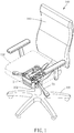
- An elastic seesaw-type tilting mechanism 1 includes a base support 10, a seat support 20, a backrest support 30, a first elastic mechanism 40 and a second elastic mechanism 50.
- the base support 10 is configured to be connected with a chair base 101 through a chair column 104;
- the seat support 20 is pivotably mounted on the base support 10 and configured to be connected with a seat 102;
- the backrest support 30 is pivotably mounted on the base support 10 and configured to be connected with a backrest 103;
- the first elastic mechanism 40 is connected with the seat support 20 and the backrest support 30 to form an elastic seesaw mechanism;
- the second elastic mechanism 50 is connected with the base support 10 and the seat support 20, the second elastic mechanism 50 and the first elastic mechanism 40 are respectively biased against the seat support 20 in opposite directions. Therefore, the seat 102 and the backrest 103 are independently free adjustable within a sufficient range.
- the base support 10, the seat support 20 and the backrest support 30 are pivotably mounted on a shaft 60, and the shaft 60 serves as a fulcrum and a pivot axis of the first elastic mechanism 40 and the elastic seesaw mechanism.
- the first elastic mechanism 40 is a torsion spring and connected with the shaft 60.
- the first elastic mechanism 40 is pivotably disposed around the shaft 60.
- the first elastic mechanism may be a flat spring, torsion bar, compression spring, extension spring or other elastic or resilient members capable of providing elastic potential energy; the first elastic mechanism may include two elastic components (such as elastic or resilient members described above) or be configured with any of the elastic or resilient members described above to exert force on the seat support and the backrest support.
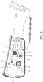
- One of the base support 10 and the backrest support 30 includes at least one guiding groove, and the other of the base support 10 and the backrest support 30 includes at least one guiding member movably disposed within the at least one guiding groove.
- the base support 10 includes at least one guiding groove 11
- the backrest support 30 includes at least one guiding member 31 movably disposed within the at least one guiding groove 11.
- the at least one guiding groove 11 is an arcuate groove so that the backrest support 30 is stably and smoothly swingable along the at least one guiding groove 11.
- the second elastic mechanism 50 includes at least one compression spring or extension spring which is abutted against or connected between the base support 10 and the seat support 20.
- the second elastic mechanism 50 is a compression spring.
- the seat support 20 further includes a seat support adjusting shaft 21, two ends of the torsion spring respectively bias the guiding member 31 and the seat support adjusting shaft 21 in opposite directions, the compression spring and the torsion spring respectively exert force on the seat support 20 at opposite sides of the shaft 60 so that the seat support 20 is under a torque balance state.
- the base support 10 and the seat support 20 may, respectively, include a receiving groove, a column or the like configured for the compression spring to be stably disposed thereon.
- the second elastic mechanism may be configured to include a compression spring and an extension spring, or a flat spring, torsion bar or other elastic or resilient members capable of providing elastic potential energy.
- the second elastic mechanism is configured to provide an elastic force which is upward exerted on the seat support, and a direction of the elastic force is opposite to a force that the first elastic mechanism exerted on the seat support so as to provide balance effect. Therefore, the seat and the backrest can automatically and steplessly balance with each other so as to be suitable for various users' requirements.
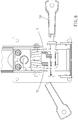
- the elastic seesaw-type tilting mechanism 1 further includes an associated lock mechanism 70
- the base support 10 includes a lock axle 12.
- the associated lock mechanism 70 includes a seat support locking member 71 which is connected with the seat support 20 and adjustably connected with the lock axle 12, a backrest support locking member 72 which is connected with the backrest support 30 and adjustably connected with the lock axle 12, and a locking device 73 which is operable to lock or unlock the lock axle 12, the seat support locking member 71 and the backrest support locking member 72.
- the lock axle 12 is disposed through a guiding groove 711 of the seat support locking member 71 and a guiding groove 721 of the backrest support locking member 72, the guiding groove 711 of the seat support locking member 71 and the guiding grooves 721 of the backrest support locking member 72 allow movement of the seat support locking member 71 and the backrest support locking member 72 relative to the lock axle 12.
- the guiding grooves 711, 721 are arcuate grooves so that the seat support 20 and the backrest support 30 are stably and smoothly swingable along the guiding grooves 711, 721 respectively.
- the locking device 73 includes a lever 731 disposed on the base support 10 and a compression spring 732 sleeved on the lock axle 12.
- An end of the lever 731 includes a rolling portion 733 (such as a roller) which is movable by pulling the lever 731 so as to lock or unlock the seat support locking member 71 and the backrest support locking member 72.
- the compression spring may be any other components and materials configured to lock or unlock the seat support locking member and the backrest support locking member.
- the locking device may include a plurality of positioning holes which are disposed on the seat support or/and the backrest support and at least one pin disposed on the base support, the at least one pin may be restrictedly moved, by a lever or cable for example, and inserted within one of the plurality of positioning holes after adjustment so as to maintain a configuration of the elastic seesaw-type tilting mechanism.
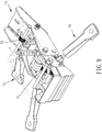
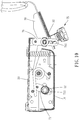
- FIGS 9 to 11 show another preferable embodiment of the present invention.
- the elastic seesaw-type tilting mechanism 1a further includes a seat support locking device 74, a backrest support locking device 75, a seat support locking member 71 and a backrest support locking member 76.
- the base support 10 includes a lock axle 12
- the backrest support 30 includes a lock axle 32
- the seat support locking member 71 is connected with the seat support 20 and adjustably connected with the lock axle 12 of the base support 10.
- the backrest support locking member 76 is connected with the seat support 20 and adjustably connected with the lock axle 32 of the backrest support 30.
- the seat support locking device 74 is operable to lock or unlock the seat support locking member 71 and the lock axle 12 of the base support 10
- the backrest support locking device 75 is operable to lock or unlock the backrest support locking member 76 and the lock axle 32 of the backrest support 30.
- the lock axle 12 of the base support 10 is disposed through a guiding groove 711 of the seat support locking member 71, and the guiding groove of the seat support locking member 71 allows movement of the seat support locking member 71 relative to the lock axle 12 of the base support 10.
- the lock axle 32 of the backrest support 30 is disposed through a guiding groove 761 of the backrest support locking member 76, and the guiding groove 761 of the backrest support locking member 76 allows movement of the backrest support locking member 76 relative to the lock axle 32 of the backrest support 30. Therefore, the seat support 20 and the backrest support 30 are adjustable and positioned independently.
- the present invention further provides a swivel chair 100 which includes one of the elastic seesaw-type tilting mechanisms described above, further including a seat 102, a backrest 103, a chair column 104 and a chair base 101.
- the chair column 104 is a gas spring, and the gas spring is raisably connected between the base support 10 and the chair base 101 and the base support 10 is liftable relative to the chair base 101.
- the elastic seesaw-type tilting mechanism of the present invention allows the seat and the backrest to be adjustable and lockable independently or simultaneously so as to meet individual requirements.
- the swivel chair with the elastic seesaw-type tilting mechanism can sufficiently satisfy the user's requirements for reclining comfortability and increase delight in using experience.
Landscapes
- Health & Medical Sciences (AREA)
- Dentistry (AREA)
- General Health & Medical Sciences (AREA)
- Chairs Characterized By Structure (AREA)
- Chairs For Special Purposes, Such As Reclining Chairs (AREA)
- Chair Legs, Seat Parts, And Backrests (AREA)
Claims (10)
- Elastischer wippenartiger Kippmechanismus (1, 1a), umfassend:eine Basisstütze (10), die konfiguriert ist, durch eine Stuhlsäule (104) mit einer Stuhlbasis (101) verbunden zu sein,eine Sitzstütze (20), die schwenkbar an der Basisstütze (10) montiert ist und konfiguriert ist, mit einem Sitz (102) verbunden zu sein,eine Rückenlehnenstütze (30), die schwenkbar an der Basisstütze (10) montiert ist und konfiguriert ist, mit einer Rückenlehne (103) verbunden zu sein,einen ersten elastischen Mechanismus (40), der mit der Sitzstütze (20) und der Rückenlehnenstütze (30) verbunden ist, um einen elastischen Wippenmechanismus auszubilden, undeinen zweiten elastischen Mechanismus (50), der mit der Basisstütze (10) und der Sitzstütze (20) verbunden ist, wobei der zweite elastische Mechanismus (50) und der erste elastische Mechanismus (40) entsprechend in entgegengesetzte Richtungen gegen die Sitzstütze (20) vorgespannt sind,dadurch gekennzeichnet, dassdie Basisstütze (10), die Sitzstütze (20) und die Rückenlehnenstütze (30) schwenkbar an einem Schaft (60) montiert sind, wobei der erste elastische Mechanismus (40) schwenkbar um den Schaft (60) angeordnet ist und der Schaft (60) als ein Drehpunkt und als eine Drehachse des ersten elastischen Mechanismus (40) und des elastischen Wippenmechanismus dient.
- Elastischer wippenartiger Kippmechanismus (1, 1a) gemäß Anspruch 1, bei welchem der zweite elastische Mechanismus (50) zwischen der Basisstütze (10) und der Sitzstütze (20) angeordnet ist.
- Elastischer wippenartiger Kippmechanismus (1, 1a) gemäß Anspruch 1, bei welchem entweder die Basisstütze (10) oder die Rückenlehnenstütze (30) zumindest eine Führungsnut (11) umfassen und die Andere von der Basisstütze (10) und der Rückenlehnenstütze (30) zumindest ein Führungselement (31) umfasst, das innerhalb der zumindest einen Führungsnut (11) beweglich angeordnet ist.
- Elastischer wippenartiger Kippmechanismus (1, 1a) gemäß Anspruch 1, der ferner einen zugehörigen Verriegelungsmechanismus (70) umfasst, wobei die Basisstütze (10) eine Verriegelungsachse (12) umfasst, wobei der zugehörige Verriegelungsmechanismus (70) ein Sitzstützenverriegelungselement (71), das mit der Sitzstütze (20) verbunden ist und einstellbar mit der Verriegelungsachse (12) verbunden ist, ein Rückenlehnenstützenverriegelungselement (72), das mit der Rückenlehnenstütze (30) verbunden ist und einstellbar mit der Verriegelungsachse (12) verbunden ist, und eine Verriegelungsvorrichtung (73) umfasst, die verwendet werden kann, um die Verriegelungsachse (12), das Sitzstützenverriegelungselement (71) und das Rückenlehnenstützenverriegelungselement (72) zu verriegeln oder zu entriegeln.
- Elastischer wippenartiger Kippmechanismus (1, 1a) gemäß Anspruch 4, bei welchem die Verriegelungsachse (12) durch eine Führungsnut (711) des Sitzstützenverriegelungselements (71) und eine Führungsnut (721) des Rückenlehnenstützenverriegelungselements (72) angeordnet ist, wobei die Führungsnut (711) des Sitzstützenverriegelungselements (71) und die Führungsnut (721) des Rückenlehnenstützenverriegelungselements (72) eine Bewegung des Sitzstützenverriegelungselements (71) und des Rückenlehnenstützenverriegelungselements (72) relativ zu der Verriegelungsachse (12) erlauben.
- Elastischer wippenartiger Kippmechanismus (1, 1a) gemäß Anspruch 1, der ferner eine Sitzstützenverriegelungsvorrichtung (74), eine Rückenlehnenstützenverriegelungsvorrichtung (75), ein Sitzstützenverriegelungselement (71) und ein Rückenlehnenstützenverriegelungselement (76) umfasst, wobei die Basisstütze (10) eine Verriegelungsachse (12) umfasst, die Rückenlehnenstütze (30) eine Verriegelungsachse (32) umfasst und das Sitzstützenverriegelungselement (71) mit der Sitzstütze (20) verbunden und einstellbar mit der Verriegelungsachse (12) der Basisstütze (10) verbunden ist, wobei das Rückenlehnenstützenverriegelungselement (76) mit der Sitzstütze (20) verbunden und einstellbar mit der Verriegelungsachse (32) der Rückenlehnenstütze (30) verbunden ist, wobei die Sitzstützenverriegelungsvorrichtung (74) verwendet werden kann, um das Sitzstützenverriegelungselement (71) und die Verriegelungsachse (12) der Basisstütze (10) zu verriegeln oder zu entriegeln und das Rückenlehnenstützenverriegelungselement (75) verwendbar ist, um das Rückenlehnenstützenverriegelungselement (76) und die Verriegelungsachse (32) der Rückenlehnenstütze (30) zu verriegeln oder zu entriegeln.
- Elastischer wippenartiger Kippmechanismus (1, 1a) gemäß Anspruch 6, bei welchem die Verriegelungsachse (12) der Basisstütze (10) durch eine Führungsnut (711) des Sitzstützenverriegelungselements (71) angeordnet ist, wobei die Führungsnut (711) des Sitzstützenverriegelungselements (71) eine Bewegung des Sitzstützenverriegelungselements (71) relativ zu der Verriegelungsachse (12) der Basisstütze (10) erlaubt, wobei die Verriegelungsachse (32) der Rückenlehnenstütze (30) durch eine Führungsnut (761) des Rückenlehnenstützenverriegelungselements (76) angeordnet ist und die Führungsnut (761) des Rückenlehnenstützenverriegelungselements (76) eine Bewegung des Rückenlehnenstützenverriegelungselements (76) relativ zu der Verriegelungsachse (32) der Rückenlehnenstütze (30) erlaubt.
- Elastischer wippenartiger Kippmechanismus (1, 1a) gemäß Anspruch 5, bei welchem der zweite elastische Mechanismus (50) zwischen der Basisstütze (10) und der Sitzstütze (20) angeordnet ist, wobei die Basisstütze (10) zumindest eine Führungsnut (11) umfasst und die Rückenlehnenstütze (30) zumindest ein Führungselement (31) umfasst, das beweglich innerhalb der zumindest einen Führungsnut (11) angeordnet ist, wobei die Sitzstütze (20) ferner eine Sitzstützeneinstellstange (21) umfasst, wobei zwei Enden des ersten elastischen Mechanismus (40) entsprechend das Führungselement (31) und die Sitzstützeneinstellstange (21) in entgegengesetzte Richtungen vorspannen, wobei der erste elastische Mechanismus (40) und der zweite elastische Mechanismus (50) entsprechend in entgegengesetzte Richtungen, Kraft auf die Sitzstütze (20) ausüben, so dass die Sitzstütze (20) in einem Drehmomentausgleichszustand ist.
- Drehstuhl (100), der den elastischen wippenartigen Kippmechanismus (1, 1a) gemäß einem der vorhergehenden Ansprüche umfasst, der ferner einen Sitz (102), eine Rückenlehne (103), eine Stuhlsäule (104) und eine Stuhlbasis (101) umfasst, wobei die Rückenlehne (103) mit der Rückenlehnenstütze (30) verbunden ist.
- Drehstuhl (100) gemäß Anspruch 9, bei welchem die Stuhlsäule (104) eine Gasfeder ist und die Basisstütze (10) relativ zu der Stuhlbasis (101) anhebbar ist.
Applications Claiming Priority (1)
| Application Number | Priority Date | Filing Date | Title |
|---|---|---|---|
| CN201810378091.0A CN108371436B (zh) | 2018-04-25 | 2018-04-25 | 弹力跷跷板式的自由倾仰机构及自由调节转椅 |
Publications (2)
| Publication Number | Publication Date |
|---|---|
| EP3560381A1 EP3560381A1 (de) | 2019-10-30 |
| EP3560381B1 true EP3560381B1 (de) | 2020-11-25 |
Family
ID=63032859
Family Applications (1)
| Application Number | Title | Priority Date | Filing Date |
|---|---|---|---|
| EP19159530.5A Active EP3560381B1 (de) | 2018-04-25 | 2019-02-26 | Elastischer wippenartiger kippmechanismus und drehstuhl damit |
Country Status (5)
| Country | Link |
|---|---|
| US (1) | US10687626B2 (de) |
| EP (1) | EP3560381B1 (de) |
| JP (1) | JP6667693B2 (de) |
| CN (1) | CN108371436B (de) |
| TW (1) | TWI681739B (de) |
Families Citing this family (8)
| Publication number | Priority date | Publication date | Assignee | Title |
|---|---|---|---|---|
| KR102245900B1 (ko) * | 2020-10-30 | 2021-04-30 | 주식회사 토퍼스 | 의자 좌판 및 등판 지지 구조 |
| KR102499915B1 (ko) * | 2020-11-05 | 2023-02-15 | 김태욱 | 의자 좌판 지지 구조 |
| KR102277397B1 (ko) * | 2020-11-25 | 2021-07-14 | 주식회사 토퍼스 | 의자 좌판 및 등판 지지 구조 |
| CN113229661A (zh) * | 2021-06-17 | 2021-08-10 | 江山市奇栖正机电科技有限公司 | 一种助力人体复位的椅子躺托 |
| CN113749449B (zh) * | 2021-09-16 | 2024-04-16 | 嘉兴市永泰五金塑料有限责任公司 | 一种具有旋转结构的办公椅底盘 |
| CN114228583A (zh) * | 2021-12-14 | 2022-03-25 | 奇瑞汽车股份有限公司 | 汽车座椅座盆结构 |
| IT202200009566A1 (it) * | 2022-05-10 | 2023-11-10 | Brado S P A | Dispositivo di regolazione per una sedia con meccanismo oscillante |
| IT202200009572A1 (it) * | 2022-05-10 | 2023-11-10 | Brado S P A | Dispositivo di regolazione per una sedia con meccanismo oscillante. |
Family Cites Families (38)
| Publication number | Priority date | Publication date | Assignee | Title |
|---|---|---|---|---|
| DE7312840U (de) * | 1974-09-12 | Kerstholt F | Sitz- und/oder Liegemöbel mit bewegbarem Rückenteil | |
| DE2335586A1 (de) * | 1973-01-29 | 1975-01-30 | Fritz Kerstholt | Sitz- und/oder liegemoebel mit bewegbarem rueckenteil |
| US4494795A (en) * | 1982-05-06 | 1985-01-22 | Steelcase Inc. | Variable back adjuster for chairs |
| ATE18124T1 (de) * | 1982-10-13 | 1986-03-15 | Stoll Gmbh Martin | Stuhl. |
| DE3930361C2 (de) * | 1989-09-12 | 1993-11-04 | Simon Desanta | Stuhl, insbesondere buerostuhl |
| NO174135C (no) * | 1990-09-05 | 1994-03-23 | Staal & Stil As | Arbeidsstol |
| JPH0755959Y2 (ja) * | 1990-12-26 | 1995-12-25 | 株式会社イトーキクレビオ | 椅子における傾動制御装置 |
| JPH085637Y2 (ja) * | 1990-12-26 | 1996-02-21 | 株式会社イトーキクレビオ | 椅子の傾動制御装置 |
| JP3330145B2 (ja) * | 1991-05-21 | 2002-09-30 | 株式会社イトーキ | 椅子の背,座部の連動支持機構 |
| JPH0613596U (ja) * | 1992-07-20 | 1994-02-22 | メーコー工業株式会社 | 事務用椅子 |
| DE4324541A1 (de) * | 1993-07-22 | 1995-01-26 | Trendoffice Bueromoebel | Stuhl, insbesondere Bürostuhl |
| DE69600110T2 (de) * | 1996-04-22 | 1998-06-04 | Steelcase Strafor Sa | Verbesserungen an Verstell- und Bedienungsvorrichtungen von bewegenden und verformbaren Teilen eines Bürostuhls |
| IT245520Y1 (it) * | 1998-07-16 | 2002-03-22 | Beniamino Miotto | Dispositivo meccanico particolarmente per la movimentazione sincronadi sedile e schienale di una sedia. |
| DE10026292C2 (de) * | 1999-07-06 | 2003-03-20 | Roeder Peter | Stuhl |
| US6582019B2 (en) * | 2000-03-17 | 2003-06-24 | Herman Miller, Inc. | Tilt assembly for a chair |
| TW499912U (en) * | 2000-09-07 | 2002-08-21 | Wen-Long Wu | Improved adjustment structure of chair |
| RU2199258C1 (ru) * | 2002-02-14 | 2003-02-27 | Быков Алексей Алексеевич | Устройство для сидения |
| JP3967150B2 (ja) * | 2002-02-28 | 2007-08-29 | 株式会社イトーキ | 椅子 |
| TWI260977B (en) * | 2005-02-05 | 2006-09-01 | Tung Yu O A Co Ltd | Chair seat with slipping function |
| US7866750B2 (en) * | 2006-01-12 | 2011-01-11 | Bock 1 Gmbh & Co. Kg | Permanent contact mechanism |
| CA2646948A1 (en) * | 2006-03-24 | 2007-10-04 | Herman Miller Inc. | Piece of furniture |
| JP2008302063A (ja) * | 2007-06-08 | 2008-12-18 | Itoki Corp | 椅子 |
| DE202008011703U1 (de) * | 2008-02-22 | 2009-07-02 | Bock 1 Gmbh & Co. Kg | Mechanik für einen Bürostuhl |
| GB201015414D0 (en) * | 2010-09-15 | 2010-10-27 | Birkbeck Hilary R | Link chair action |
| DE102011081588A1 (de) * | 2011-08-25 | 2013-02-28 | Johannes Uhlenbrock | Synchronmechanik für einen Stuhl |
| JP6009891B2 (ja) * | 2011-11-04 | 2016-10-19 | 株式会社岡村製作所 | 椅子 |
| WO2013177690A1 (en) * | 2012-06-01 | 2013-12-05 | Duke Aaron | Chair and chair tilt control assembly |
| DE202013100574U1 (de) * | 2013-02-07 | 2014-05-08 | Bock 1 Gmbh & Co. Kg | Mechanik für einen Bürostuhl |
| US8939509B2 (en) * | 2013-04-11 | 2015-01-27 | Hangzhou Zhongtai Industrial Group Co., Ltd. | Chair chassis |
| CN203555393U (zh) * | 2013-09-24 | 2014-04-23 | 浙江永艺家具股份有限公司 | 一种自动回位的转椅底盘 |
| CN103479112A (zh) * | 2013-09-24 | 2014-01-01 | 浙江永艺家具股份有限公司 | 一种转椅底盘 |
| DE102014104870A1 (de) * | 2014-04-04 | 2015-10-08 | Bock 1 Gmbh & Co. Kg | Mechanik für einen Bürostuhl |
| CN104207520B (zh) * | 2014-09-18 | 2017-02-22 | 永艺家具股份有限公司 | 用于转椅底盘的椅背翘板锁定机构 |
| CN107625323B (zh) * | 2016-07-18 | 2024-04-26 | 永艺家具股份有限公司 | 一种用于办公椅底盘的托架驱动机构 |
| CN107625324B (zh) * | 2016-07-18 | 2024-04-12 | 永艺家具股份有限公司 | 一种办公椅底盘及办公椅 |
| WO2018034139A1 (ja) * | 2016-08-18 | 2018-02-22 | 株式会社クオリ | 傾動可能なスツールまたはラウンジチェア |
| CN106388358A (zh) * | 2016-09-30 | 2017-02-15 | 广西大学 | 一种同步倾仰底盘和具有该底盘的办公椅 |
| CN208709033U (zh) * | 2018-04-25 | 2019-04-09 | 严澄宇 | 弹力跷跷板式的自由倾仰机构及自由调节转椅 |
-
2018
- 2018-04-25 CN CN201810378091.0A patent/CN108371436B/zh active Active
-
2019
- 2019-01-16 TW TW108101696A patent/TWI681739B/zh not_active IP Right Cessation
- 2019-02-26 EP EP19159530.5A patent/EP3560381B1/de active Active
- 2019-02-27 JP JP2019034011A patent/JP6667693B2/ja active Active
- 2019-03-04 US US16/291,468 patent/US10687626B2/en active Active
Non-Patent Citations (1)
| Title |
|---|
| None * |
Also Published As
| Publication number | Publication date |
|---|---|
| JP6667693B2 (ja) | 2020-03-18 |
| TW201944936A (zh) | 2019-12-01 |
| US20190328139A1 (en) | 2019-10-31 |
| CN108371436B (zh) | 2023-10-27 |
| CN108371436A (zh) | 2018-08-07 |
| EP3560381A1 (de) | 2019-10-30 |
| JP2019188126A (ja) | 2019-10-31 |
| TWI681739B (zh) | 2020-01-11 |
| US10687626B2 (en) | 2020-06-23 |
Similar Documents
| Publication | Publication Date | Title |
|---|---|---|
| EP3560381B1 (de) | Elastischer wippenartiger kippmechanismus und drehstuhl damit | |
| US7234775B2 (en) | Dynamically balanced seat assembly having independently and arcuately movable seat and backrest and method | |
| US5975640A (en) | Adjustable armrest of an office chair | |
| US20080100121A1 (en) | Dynamically balanced seat assembly having independently and arcuately movable backrest and method | |
| JPH0243481B2 (de) | ||
| US20040066075A1 (en) | Structure for adjusting backrest for collapsible chairs | |
| CN1937936A (zh) | 具有倾斜锁定装置的座椅 | |
| GB2415621A (en) | Portable massage chair | |
| US20170020290A1 (en) | Mechanism for an office chair | |
| US7147282B2 (en) | Chair with backrest depth adjustment mechanism | |
| US5560682A (en) | Adjustment mechanism for a chair | |
| US20200383484A1 (en) | Chair backrest adjustment mechanism | |
| US7467826B1 (en) | Resilience tilt-adjusted device of backrest | |
| CN102038377B (zh) | 调整机构及可调倾角的座椅 | |
| JP3177652U (ja) | 椅子の座部ガイド装置 | |
| EP2389840B1 (de) | Stuhlanpassungsstruktur | |
| US7431397B2 (en) | Chair | |
| AU2020200787B1 (en) | Elastic seesaw-type variable tilting ratio mechanism and swivel chair having the same | |
| US20070007810A1 (en) | Angle adjustable armrest assembly | |
| KR102303651B1 (ko) | 의자용 좌판의 국부 변동 구조 | |
| JPH10179312A (ja) | 椅子における座板又は背もたれの弾力調節装置 | |
| JP3644518B2 (ja) | 椅子 | |
| KR101753786B1 (ko) | 위치 조절이 가능한 팔걸이가 구비된 의자 | |
| EP3785570B1 (de) | Stuhlsitz mit einem gleit- und verriegelungsmechanismus | |
| CA3060300C (en) | Chair seat sliding and locking mechanism |
Legal Events
| Date | Code | Title | Description |
|---|---|---|---|
| PUAI | Public reference made under article 153(3) epc to a published international application that has entered the european phase |
Free format text: ORIGINAL CODE: 0009012 |
|
| STAA | Information on the status of an ep patent application or granted ep patent |
Free format text: STATUS: THE APPLICATION HAS BEEN PUBLISHED |
|
| AK | Designated contracting states |
Kind code of ref document: A1 Designated state(s): AL AT BE BG CH CY CZ DE DK EE ES FI FR GB GR HR HU IE IS IT LI LT LU LV MC MK MT NL NO PL PT RO RS SE SI SK SM TR |
|
| AX | Request for extension of the european patent |
Extension state: BA ME |
|
| STAA | Information on the status of an ep patent application or granted ep patent |
Free format text: STATUS: REQUEST FOR EXAMINATION WAS MADE |
|
| 17P | Request for examination filed |
Effective date: 20200102 |
|
| RBV | Designated contracting states (corrected) |
Designated state(s): AL AT BE BG CH CY CZ DE DK EE ES FI FR GB GR HR HU IE IS IT LI LT LU LV MC MK MT NL NO PL PT RO RS SE SI SK SM TR |
|
| GRAP | Despatch of communication of intention to grant a patent |
Free format text: ORIGINAL CODE: EPIDOSNIGR1 |
|
| STAA | Information on the status of an ep patent application or granted ep patent |
Free format text: STATUS: GRANT OF PATENT IS INTENDED |
|
| INTG | Intention to grant announced |
Effective date: 20200603 |
|
| GRAS | Grant fee paid |
Free format text: ORIGINAL CODE: EPIDOSNIGR3 |
|
| GRAA | (expected) grant |
Free format text: ORIGINAL CODE: 0009210 |
|
| STAA | Information on the status of an ep patent application or granted ep patent |
Free format text: STATUS: THE PATENT HAS BEEN GRANTED |
|
| AK | Designated contracting states |
Kind code of ref document: B1 Designated state(s): AL AT BE BG CH CY CZ DE DK EE ES FI FR GB GR HR HU IE IS IT LI LT LU LV MC MK MT NL NO PL PT RO RS SE SI SK SM TR |
|
| REG | Reference to a national code |
Ref country code: GB Ref legal event code: FG4D |
|
| REG | Reference to a national code |
Ref country code: CH Ref legal event code: EP |
|
| REG | Reference to a national code |
Ref country code: DE Ref legal event code: R096 Ref document number: 602019001415 Country of ref document: DE |
|
| REG | Reference to a national code |
Ref country code: AT Ref legal event code: REF Ref document number: 1337284 Country of ref document: AT Kind code of ref document: T Effective date: 20201215 |
|
| REG | Reference to a national code |
Ref country code: IE Ref legal event code: FG4D |
|
| REG | Reference to a national code |
Ref country code: AT Ref legal event code: MK05 Ref document number: 1337284 Country of ref document: AT Kind code of ref document: T Effective date: 20201125 |
|
| REG | Reference to a national code |
Ref country code: NL Ref legal event code: MP Effective date: 20201125 |
|
| PG25 | Lapsed in a contracting state [announced via postgrant information from national office to epo] |
Ref country code: GR Free format text: LAPSE BECAUSE OF FAILURE TO SUBMIT A TRANSLATION OF THE DESCRIPTION OR TO PAY THE FEE WITHIN THE PRESCRIBED TIME-LIMIT Effective date: 20210226 Ref country code: NO Free format text: LAPSE BECAUSE OF FAILURE TO SUBMIT A TRANSLATION OF THE DESCRIPTION OR TO PAY THE FEE WITHIN THE PRESCRIBED TIME-LIMIT Effective date: 20210225 Ref country code: FI Free format text: LAPSE BECAUSE OF FAILURE TO SUBMIT A TRANSLATION OF THE DESCRIPTION OR TO PAY THE FEE WITHIN THE PRESCRIBED TIME-LIMIT Effective date: 20201125 Ref country code: RS Free format text: LAPSE BECAUSE OF FAILURE TO SUBMIT A TRANSLATION OF THE DESCRIPTION OR TO PAY THE FEE WITHIN THE PRESCRIBED TIME-LIMIT Effective date: 20201125 Ref country code: PT Free format text: LAPSE BECAUSE OF FAILURE TO SUBMIT A TRANSLATION OF THE DESCRIPTION OR TO PAY THE FEE WITHIN THE PRESCRIBED TIME-LIMIT Effective date: 20210325 |
|
| PG25 | Lapsed in a contracting state [announced via postgrant information from national office to epo] |
Ref country code: AT Free format text: LAPSE BECAUSE OF FAILURE TO SUBMIT A TRANSLATION OF THE DESCRIPTION OR TO PAY THE FEE WITHIN THE PRESCRIBED TIME-LIMIT Effective date: 20201125 Ref country code: SE Free format text: LAPSE BECAUSE OF FAILURE TO SUBMIT A TRANSLATION OF THE DESCRIPTION OR TO PAY THE FEE WITHIN THE PRESCRIBED TIME-LIMIT Effective date: 20201125 Ref country code: LV Free format text: LAPSE BECAUSE OF FAILURE TO SUBMIT A TRANSLATION OF THE DESCRIPTION OR TO PAY THE FEE WITHIN THE PRESCRIBED TIME-LIMIT Effective date: 20201125 Ref country code: IS Free format text: LAPSE BECAUSE OF FAILURE TO SUBMIT A TRANSLATION OF THE DESCRIPTION OR TO PAY THE FEE WITHIN THE PRESCRIBED TIME-LIMIT Effective date: 20210325 Ref country code: PL Free format text: LAPSE BECAUSE OF FAILURE TO SUBMIT A TRANSLATION OF THE DESCRIPTION OR TO PAY THE FEE WITHIN THE PRESCRIBED TIME-LIMIT Effective date: 20201125 Ref country code: BG Free format text: LAPSE BECAUSE OF FAILURE TO SUBMIT A TRANSLATION OF THE DESCRIPTION OR TO PAY THE FEE WITHIN THE PRESCRIBED TIME-LIMIT Effective date: 20210225 |
|
| REG | Reference to a national code |
Ref country code: LT Ref legal event code: MG9D |
|
| PG25 | Lapsed in a contracting state [announced via postgrant information from national office to epo] |
Ref country code: HR Free format text: LAPSE BECAUSE OF FAILURE TO SUBMIT A TRANSLATION OF THE DESCRIPTION OR TO PAY THE FEE WITHIN THE PRESCRIBED TIME-LIMIT Effective date: 20201125 |
|
| PG25 | Lapsed in a contracting state [announced via postgrant information from national office to epo] |
Ref country code: RO Free format text: LAPSE BECAUSE OF FAILURE TO SUBMIT A TRANSLATION OF THE DESCRIPTION OR TO PAY THE FEE WITHIN THE PRESCRIBED TIME-LIMIT Effective date: 20201125 Ref country code: LT Free format text: LAPSE BECAUSE OF FAILURE TO SUBMIT A TRANSLATION OF THE DESCRIPTION OR TO PAY THE FEE WITHIN THE PRESCRIBED TIME-LIMIT Effective date: 20201125 Ref country code: EE Free format text: LAPSE BECAUSE OF FAILURE TO SUBMIT A TRANSLATION OF THE DESCRIPTION OR TO PAY THE FEE WITHIN THE PRESCRIBED TIME-LIMIT Effective date: 20201125 Ref country code: SM Free format text: LAPSE BECAUSE OF FAILURE TO SUBMIT A TRANSLATION OF THE DESCRIPTION OR TO PAY THE FEE WITHIN THE PRESCRIBED TIME-LIMIT Effective date: 20201125 Ref country code: SK Free format text: LAPSE BECAUSE OF FAILURE TO SUBMIT A TRANSLATION OF THE DESCRIPTION OR TO PAY THE FEE WITHIN THE PRESCRIBED TIME-LIMIT Effective date: 20201125 Ref country code: CZ Free format text: LAPSE BECAUSE OF FAILURE TO SUBMIT A TRANSLATION OF THE DESCRIPTION OR TO PAY THE FEE WITHIN THE PRESCRIBED TIME-LIMIT Effective date: 20201125 |
|
| REG | Reference to a national code |
Ref country code: DE Ref legal event code: R097 Ref document number: 602019001415 Country of ref document: DE |
|
| PG25 | Lapsed in a contracting state [announced via postgrant information from national office to epo] |
Ref country code: DK Free format text: LAPSE BECAUSE OF FAILURE TO SUBMIT A TRANSLATION OF THE DESCRIPTION OR TO PAY THE FEE WITHIN THE PRESCRIBED TIME-LIMIT Effective date: 20201125 |
|
| PG25 | Lapsed in a contracting state [announced via postgrant information from national office to epo] |
Ref country code: MC Free format text: LAPSE BECAUSE OF FAILURE TO SUBMIT A TRANSLATION OF THE DESCRIPTION OR TO PAY THE FEE WITHIN THE PRESCRIBED TIME-LIMIT Effective date: 20201125 |
|
| PLBE | No opposition filed within time limit |
Free format text: ORIGINAL CODE: 0009261 |
|
| STAA | Information on the status of an ep patent application or granted ep patent |
Free format text: STATUS: NO OPPOSITION FILED WITHIN TIME LIMIT |
|
| REG | Reference to a national code |
Ref country code: BE Ref legal event code: MM Effective date: 20210228 |
|
| PG25 | Lapsed in a contracting state [announced via postgrant information from national office to epo] |
Ref country code: LU Free format text: LAPSE BECAUSE OF NON-PAYMENT OF DUE FEES Effective date: 20210226 Ref country code: NL Free format text: LAPSE BECAUSE OF FAILURE TO SUBMIT A TRANSLATION OF THE DESCRIPTION OR TO PAY THE FEE WITHIN THE PRESCRIBED TIME-LIMIT Effective date: 20201125 Ref country code: AL Free format text: LAPSE BECAUSE OF FAILURE TO SUBMIT A TRANSLATION OF THE DESCRIPTION OR TO PAY THE FEE WITHIN THE PRESCRIBED TIME-LIMIT Effective date: 20201125 |
|
| 26N | No opposition filed |
Effective date: 20210826 |
|
| PG25 | Lapsed in a contracting state [announced via postgrant information from national office to epo] |
Ref country code: SI Free format text: LAPSE BECAUSE OF FAILURE TO SUBMIT A TRANSLATION OF THE DESCRIPTION OR TO PAY THE FEE WITHIN THE PRESCRIBED TIME-LIMIT Effective date: 20201125 |
|
| PG25 | Lapsed in a contracting state [announced via postgrant information from national office to epo] |
Ref country code: ES Free format text: LAPSE BECAUSE OF FAILURE TO SUBMIT A TRANSLATION OF THE DESCRIPTION OR TO PAY THE FEE WITHIN THE PRESCRIBED TIME-LIMIT Effective date: 20201125 Ref country code: IE Free format text: LAPSE BECAUSE OF NON-PAYMENT OF DUE FEES Effective date: 20210226 |
|
| PG25 | Lapsed in a contracting state [announced via postgrant information from national office to epo] |
Ref country code: IS Free format text: LAPSE BECAUSE OF FAILURE TO SUBMIT A TRANSLATION OF THE DESCRIPTION OR TO PAY THE FEE WITHIN THE PRESCRIBED TIME-LIMIT Effective date: 20210325 |
|
| PG25 | Lapsed in a contracting state [announced via postgrant information from national office to epo] |
Ref country code: BE Free format text: LAPSE BECAUSE OF NON-PAYMENT OF DUE FEES Effective date: 20210228 |
|
| REG | Reference to a national code |
Ref country code: CH Ref legal event code: PL |
|
| PG25 | Lapsed in a contracting state [announced via postgrant information from national office to epo] |
Ref country code: LI Free format text: LAPSE BECAUSE OF NON-PAYMENT OF DUE FEES Effective date: 20220228 Ref country code: CH Free format text: LAPSE BECAUSE OF NON-PAYMENT OF DUE FEES Effective date: 20220228 |
|
| PG25 | Lapsed in a contracting state [announced via postgrant information from national office to epo] |
Ref country code: CY Free format text: LAPSE BECAUSE OF FAILURE TO SUBMIT A TRANSLATION OF THE DESCRIPTION OR TO PAY THE FEE WITHIN THE PRESCRIBED TIME-LIMIT Effective date: 20201125 |
|
| PG25 | Lapsed in a contracting state [announced via postgrant information from national office to epo] |
Ref country code: HU Free format text: LAPSE BECAUSE OF FAILURE TO SUBMIT A TRANSLATION OF THE DESCRIPTION OR TO PAY THE FEE WITHIN THE PRESCRIBED TIME-LIMIT; INVALID AB INITIO Effective date: 20190226 |
|
| PG25 | Lapsed in a contracting state [announced via postgrant information from national office to epo] |
Ref country code: MK Free format text: LAPSE BECAUSE OF FAILURE TO SUBMIT A TRANSLATION OF THE DESCRIPTION OR TO PAY THE FEE WITHIN THE PRESCRIBED TIME-LIMIT Effective date: 20201125 |
|
| PG25 | Lapsed in a contracting state [announced via postgrant information from national office to epo] |
Ref country code: TR Free format text: LAPSE BECAUSE OF FAILURE TO SUBMIT A TRANSLATION OF THE DESCRIPTION OR TO PAY THE FEE WITHIN THE PRESCRIBED TIME-LIMIT Effective date: 20201125 |
|
| PG25 | Lapsed in a contracting state [announced via postgrant information from national office to epo] |
Ref country code: MT Free format text: LAPSE BECAUSE OF FAILURE TO SUBMIT A TRANSLATION OF THE DESCRIPTION OR TO PAY THE FEE WITHIN THE PRESCRIBED TIME-LIMIT Effective date: 20201125 |
|
| PGFP | Annual fee paid to national office [announced via postgrant information from national office to epo] |
Ref country code: FR Payment date: 20250225 Year of fee payment: 7 |
|
| PGFP | Annual fee paid to national office [announced via postgrant information from national office to epo] |
Ref country code: GB Payment date: 20260114 Year of fee payment: 8 |
|
| PGFP | Annual fee paid to national office [announced via postgrant information from national office to epo] |
Ref country code: DE Payment date: 20260227 Year of fee payment: 8 |
|
| PGFP | Annual fee paid to national office [announced via postgrant information from national office to epo] |
Ref country code: IT Payment date: 20260224 Year of fee payment: 8 |