EP3559437B1 - Ventil zum zumessen eines fluids - Google Patents
Ventil zum zumessen eines fluids Download PDFInfo
- Publication number
- EP3559437B1 EP3559437B1 EP17786914.6A EP17786914A EP3559437B1 EP 3559437 B1 EP3559437 B1 EP 3559437B1 EP 17786914 A EP17786914 A EP 17786914A EP 3559437 B1 EP3559437 B1 EP 3559437B1
- Authority
- EP
- European Patent Office
- Prior art keywords
- armature
- length
- spring
- valve
- stop element
- Prior art date
- Legal status (The legal status is an assumption and is not a legal conclusion. Google has not performed a legal analysis and makes no representation as to the accuracy of the status listed.)
- Active
Links
- 239000012530 fluid Substances 0.000 title claims description 9
- 239000000446 fuel Substances 0.000 claims description 19
- 238000002347 injection Methods 0.000 claims description 10
- 239000007924 injection Substances 0.000 claims description 10
- 238000002485 combustion reaction Methods 0.000 claims description 7
- 238000011161 development Methods 0.000 description 8
- 230000018109 developmental process Effects 0.000 description 8
- 238000007789 sealing Methods 0.000 description 4
- 230000001133 acceleration Effects 0.000 description 2
- 239000007788 liquid Substances 0.000 description 2
- 229910000831 Steel Inorganic materials 0.000 description 1
- 230000015572 biosynthetic process Effects 0.000 description 1
- 230000001914 calming effect Effects 0.000 description 1
- 238000013016 damping Methods 0.000 description 1
- 230000002349 favourable effect Effects 0.000 description 1
- 230000004907 flux Effects 0.000 description 1
- 238000009434 installation Methods 0.000 description 1
- 239000000696 magnetic material Substances 0.000 description 1
- 238000004519 manufacturing process Methods 0.000 description 1
- 239000002245 particle Substances 0.000 description 1
- 230000008092 positive effect Effects 0.000 description 1
- 239000010959 steel Substances 0.000 description 1
Images


Classifications
-
- F—MECHANICAL ENGINEERING; LIGHTING; HEATING; WEAPONS; BLASTING
- F02—COMBUSTION ENGINES; HOT-GAS OR COMBUSTION-PRODUCT ENGINE PLANTS
- F02M—SUPPLYING COMBUSTION ENGINES IN GENERAL WITH COMBUSTIBLE MIXTURES OR CONSTITUENTS THEREOF
- F02M51/00—Fuel-injection apparatus characterised by being operated electrically
- F02M51/06—Injectors peculiar thereto with means directly operating the valve needle
- F02M51/061—Injectors peculiar thereto with means directly operating the valve needle using electromagnetic operating means
- F02M51/0625—Injectors peculiar thereto with means directly operating the valve needle using electromagnetic operating means characterised by arrangement of mobile armatures
- F02M51/0664—Injectors peculiar thereto with means directly operating the valve needle using electromagnetic operating means characterised by arrangement of mobile armatures having a cylindrically or partly cylindrically shaped armature, e.g. entering the winding; having a plate-shaped or undulated armature entering the winding
- F02M51/0671—Injectors peculiar thereto with means directly operating the valve needle using electromagnetic operating means characterised by arrangement of mobile armatures having a cylindrically or partly cylindrically shaped armature, e.g. entering the winding; having a plate-shaped or undulated armature entering the winding the armature having an elongated valve body attached thereto
-
- F—MECHANICAL ENGINEERING; LIGHTING; HEATING; WEAPONS; BLASTING
- F02—COMBUSTION ENGINES; HOT-GAS OR COMBUSTION-PRODUCT ENGINE PLANTS
- F02M—SUPPLYING COMBUSTION ENGINES IN GENERAL WITH COMBUSTIBLE MIXTURES OR CONSTITUENTS THEREOF
- F02M51/00—Fuel-injection apparatus characterised by being operated electrically
- F02M51/06—Injectors peculiar thereto with means directly operating the valve needle
- F02M51/061—Injectors peculiar thereto with means directly operating the valve needle using electromagnetic operating means
- F02M51/0625—Injectors peculiar thereto with means directly operating the valve needle using electromagnetic operating means characterised by arrangement of mobile armatures
- F02M51/0664—Injectors peculiar thereto with means directly operating the valve needle using electromagnetic operating means characterised by arrangement of mobile armatures having a cylindrically or partly cylindrically shaped armature, e.g. entering the winding; having a plate-shaped or undulated armature entering the winding
- F02M51/0685—Injectors peculiar thereto with means directly operating the valve needle using electromagnetic operating means characterised by arrangement of mobile armatures having a cylindrically or partly cylindrically shaped armature, e.g. entering the winding; having a plate-shaped or undulated armature entering the winding the armature and the valve being allowed to move relatively to each other or not being attached to each other
-
- F—MECHANICAL ENGINEERING; LIGHTING; HEATING; WEAPONS; BLASTING
- F02—COMBUSTION ENGINES; HOT-GAS OR COMBUSTION-PRODUCT ENGINE PLANTS
- F02M—SUPPLYING COMBUSTION ENGINES IN GENERAL WITH COMBUSTIBLE MIXTURES OR CONSTITUENTS THEREOF
- F02M55/00—Fuel-injection apparatus characterised by their fuel conduits or their venting means; Arrangements of conduits between fuel tank and pump F02M37/00
- F02M55/008—Arrangement of fuel passages inside of injectors
-
- F—MECHANICAL ENGINEERING; LIGHTING; HEATING; WEAPONS; BLASTING
- F02—COMBUSTION ENGINES; HOT-GAS OR COMBUSTION-PRODUCT ENGINE PLANTS
- F02M—SUPPLYING COMBUSTION ENGINES IN GENERAL WITH COMBUSTIBLE MIXTURES OR CONSTITUENTS THEREOF
- F02M61/00—Fuel-injectors not provided for in groups F02M39/00 - F02M57/00 or F02M67/00
- F02M61/04—Fuel-injectors not provided for in groups F02M39/00 - F02M57/00 or F02M67/00 having valves, e.g. having a plurality of valves in series
- F02M61/10—Other injectors with elongated valve bodies, i.e. of needle-valve type
- F02M61/12—Other injectors with elongated valve bodies, i.e. of needle-valve type characterised by the provision of guiding or centring means for valve bodies
-
- F—MECHANICAL ENGINEERING; LIGHTING; HEATING; WEAPONS; BLASTING
- F02—COMBUSTION ENGINES; HOT-GAS OR COMBUSTION-PRODUCT ENGINE PLANTS
- F02M—SUPPLYING COMBUSTION ENGINES IN GENERAL WITH COMBUSTIBLE MIXTURES OR CONSTITUENTS THEREOF
- F02M61/00—Fuel-injectors not provided for in groups F02M39/00 - F02M57/00 or F02M67/00
- F02M61/16—Details not provided for in, or of interest apart from, the apparatus of groups F02M61/02 - F02M61/14
- F02M61/20—Closing valves mechanically, e.g. arrangements of springs or weights or permanent magnets; Damping of valve lift
- F02M61/205—Means specially adapted for varying the spring tension or assisting the spring force to close the injection-valve, e.g. with damping of valve lift
-
- F—MECHANICAL ENGINEERING; LIGHTING; HEATING; WEAPONS; BLASTING
- F02—COMBUSTION ENGINES; HOT-GAS OR COMBUSTION-PRODUCT ENGINE PLANTS
- F02M—SUPPLYING COMBUSTION ENGINES IN GENERAL WITH COMBUSTIBLE MIXTURES OR CONSTITUENTS THEREOF
- F02M63/00—Other fuel-injection apparatus having pertinent characteristics not provided for in groups F02M39/00 - F02M57/00 or F02M67/00; Details, component parts, or accessories of fuel-injection apparatus, not provided for in, or of interest apart from, the apparatus of groups F02M39/00 - F02M61/00 or F02M67/00; Combination of fuel pump with other devices, e.g. lubricating oil pump
- F02M63/0012—Valves
- F02M63/007—Details not provided for in, or of interest apart from, the apparatus of the groups F02M63/0014 - F02M63/0059
- F02M63/0075—Stop members in valves, e.g. plates or disks limiting the movement of armature, valve or spring
Definitions
- the invention relates to a valve for metering a fluid, in particular a fuel injection valve for internal combustion engines.
- the invention relates to the field of injectors for fuel injection systems of motor vehicles, in which fuel is preferably injected directly into the combustion chambers of an internal combustion engine.
- a valve for metering fluid is known.
- the known valve has an electromagnet for actuating a valve needle controlling a metering opening.
- the electromagnet is used to actuate an armature that is displaceable on a valve needle.
- the armature has a bore adjoining the valve needle which forms a spring receptacle for a forward stroke spring.
- This embodiment has the disadvantage that a guide between the armature and the valve needle is only implemented over a short guide length.
- valve according to the invention with the features of claim 1 has the advantage that an improved design and functionality are made possible.
- improved guidance between the armature and the valve needle and the valve needle along a longitudinal axis of the housing can be implemented.
- the armature serving as a magnet armature is not permanently connected to the valve needle, but is mounted overhung between stops.
- a stop can be formed on a stop element that can be implemented as a stop sleeve and / or stop ring.
- the stop element can also be formed in one piece with the valve needle.
- the development according to claim 2 has the advantage that the guide length between the armature and the valve needle is increased.
- the armature can be guided on its outside in the valve housing along the longitudinal axis.
- the guidance of the valve needle along the longitudinal axis is then improved accordingly over the increased guide length between the armature and the valve needle.
- the valve needle is guided via the stop element, for example on an inner pole arranged in a stationary manner in the housing, this results in an improved guidance of the armature relative to the housing.
- the further development according to claim 5 has the advantage that the guide extension can in particular be designed with an outer diameter that lies within the mouth openings of through-openings of the armature, which are used to guide a fluid through the armature. This has a positive effect on the operating behavior.
- the disadvantages of a conventional design relate firstly to the manufacturability, the costs and the assembly, if a design is implemented without a spring receptacle, in which an additional component for receiving the spring and its connection to the Anchor is required. Secondly, there are disadvantages if a pole area between the armature and the inner pole is reduced, since a lower magnetic force then occurs. This relates in particular to a possible embodiment in which a stepped bore is made on the inner pole in order to create space for a spring.
- a third disadvantage relates to a magnetic short circuit across the spring and the associated loss of magnetic force, which results in a slower build-up of force and a lower holding force in the open state. This usually affects the magnetic spring steels used, which represent a bypass for the magnetic flux between the armature and the inner pole.
- a fourth disadvantage relates to the smaller contact area between the armature and a stop ring in a variant in which the stop ring dips into the spring receptacle formed on the armature. This can lead to increased wear and tear and reduced hydraulic damping.
- a fifth disadvantage can result in a lever arm between the upper needle guide and the armature, which relates in particular to the above-mentioned embodiment, in which the stop ring dips into the spring receptacle. This can result in a large amount of needle deflection, which leads to increased wear, skewed impact and the like.
- a sixth potential disadvantage relates to designs that require a large spring diameter. Because of the limited radial installation space, lower spring forces can then be achieved, which is bad for quick armature calming after the first injection, in particular with regard to multiple injections. With the same spring force, a larger spring diameter also means a greater tilting moment on the armature, which is also disadvantageous for the injector function and in particular can result in a tilted armature stop.
- a seventh and final disadvantage relates to the risk of the spring bulging under load and the resulting contact with the inner pole and / or the stop ring due to a relatively long spring length and limited radial space. This leads to undefined friction, which, in addition to possible wear and the formation of particles, results in considerable variations in the injection behavior.
- the stop element can be made of a non-magnetic material, whereby it can separate the inner pole from the armature from a magnetic point of view.
- the lever arm can be kept short. Both a pole face and a stop face between the armature and the stop element, in particular the stop ring, can be selected to be sufficiently large.
- a relatively small Inner diameter of the spring can be realized, so that relatively high spring forces can be achieved even with a comparatively thin wire thickness of the spring.
- the spring can also be made relatively short, so that the risk of bulging and corresponding wear is reduced and a tilting moment applied to the armature in this regard remains within acceptable limits.
- the armature can be guided in the housing. Furthermore, in a further possible embodiment, an annular gap between the armature and the housing can be minimized. In relation to the given housing dimensions, this results in a quick build-up of force and a large holding force.
- the end face of the armature facing the inner pole can also be made larger than if separate through-openings are implemented.
- the development according to claim 8 has the further advantage that the flow cross-section can be enlarged disproportionately to the reduction in the area of the end face of the armature caused thereby.
- Fig. 1 shows a valve 1 for metering a fluid in a partial, schematic sectional illustration according to a first embodiment.
- the valve 1 can in particular be designed as a fuel injector 1.
- a preferred application is a fuel injection system in which such fuel injection valves 1 are designed as high pressure injection valves 1 and are used for direct injection of fuel into assigned combustion chambers of the internal combustion engine. Liquid or gaseous fuels can be used as fuel. Accordingly, the valve 1 is suitable for metering liquid or gaseous fluids.
- the valve 1 has a housing (valve housing) 2 in which an inner pole 3 is arranged in a stationary manner.
- a longitudinal axis 4 is defined by the housing 2, which here serves as a reference for guiding a valve needle 5 arranged within the housing 2. This means that the valve needle 5 should be aligned along the longitudinal axis 4 during operation.
- An armature (magnet armature) 6 is arranged on the valve needle 5.
- a stop element 7 and a further stop element 8 are also arranged on the valve needle 5. Stops 7 ', 8' are formed on the stop elements 7, 8.
- the armature 6 can be moved between the stop elements 7, 8 when actuated, an armature free path 9 being predetermined.
- the armature 6, the inner pole 3 and a magnetic coil (not shown) are components of an electromagnetic actuator 10.
- a valve closing body 11 is formed on the valve needle 5, which cooperates with a valve seat surface 12 to form a sealing seat.
- the armature 6 When the armature 6 is actuated, it is accelerated in the direction of the inner pole 3.
- the armature 6 strikes the stop 7 'of the stop element 7 and thereby actuates the valve needle 5, fuel can be injected into a space, in particular a combustion chamber, via the open sealing seat and at least one nozzle opening 13.
- the valve 1 has a return spring 14 which moves the valve needle 5 via the stop element 7 into its starting position in which the sealing seat is closed.
- the armature 6 is based on a cylindrical basic shape 20 with a through hole 21, the armature 6 being guided on the through hole 21 on the valve needle 5.
- the basic shape 20 of the armature 6 has a length L between an end face 22 facing the inner pole 3 and an end face 23 facing away from the inner pole 3.
- the armature 6 has a spring receptacle 25.
- the spring receptacle 25 is open on the end face 22 of the armature 6.
- the spring receptacle 25 has a length f along the longitudinal axis 4 between the end face 22 and a spring support surface 26 of the armature 6.
- the spring support surface 26 represents the bottom 26 of the spring receptacle 25.
- a spring 27 partially arranged in the spring receptacle 25 has a spring length F.
- the spring length F is here the spring length F of the spring 27 in the unactuated initial state.
- the spring 27 is supported on the one hand on the spring support surface 26 of the armature 6 and on the other hand on the stop 7 ′ of the stop 7.
- the spring length F is greater than the length f of the spring receptacle 25.
- the spring 27 is, however, shortened compared to its initial length F, whereby it can plunge completely into the spring receptacle 25.
- a guide web 28 is formed on the armature 6. Between the spring support surface 26 and the end face 23, the armature 6 has a (shortened) length I along the longitudinal axis 4. Without the guide web 28, only this shortened length I would be available as a guide length.
- the length I is lengthened by the length s of the guide web 28 along the longitudinal axis 4. This results in the guide length I + s in this exemplary embodiment.
- the length s of the guide web 28 is preferably selected to be equal to or even greater than the length f of the spring receptacle 25.
- the guide length I + s of the armature 6 on the valve needle 5 is equal to or even greater than the length L of the armature 6 between its end faces 22, 23.
- valve needle 5 is guided with respect to the longitudinal axis 4 or with respect to the housing 2 via the stop element 7.
- the stop element 7 is guided in a guide region 30 on an inner bore 31 of the inner pole 3. Possible configurations of the stop element 7 which enable the fluid, in particular fuel, to be advantageously passed through, are illustrated in FIG Figures 5 to 8 described.
- valve needle 5 can additionally or alternatively also be guided via the armature 6.
- the outside 32 of the armature 6 extends at least partially up to the inside 33 of the housing 2.
- an annular gap can then be implemented between the stop element 7 and the inner pole 3.
- valve needle 5 along the longitudinal axis 4 can thus be realized. This also results in an advantageous guidance between the armature 6 and the valve needle 5 over a guide length l + s, which is preferably not less than the length L.
- Fig. 2 shows a valve 1 in a partial, schematic sectional view corresponding to a second embodiment.
- a guide extension 40 is provided.
- the guide extension 40 has a length s ′ along the longitudinal axis 4, by which the guide of the armature 6 on the valve needle 5 is extended. This means that in this exemplary embodiment the guide length s ′ + I is implemented along the longitudinal axis 4 between the armature 6 and the valve needle 5.
- the spring receptacle 25 can directly adjoin the valve needle 5. This particularly facilitates the manufacture of the armature 6, since the spring receptacle 25 can be realized by a cylindrical recess aligned on the longitudinal axis 4. As a result, however, only the length I, which is shortened compared to the length L of the armature 6, which this has between the end faces 22, 23, is available directly on the basic shape 20 of the armature 6. This shortened length I is thereby to a certain extent lengthened by the length s' via the guide extension 40. Specifically, the length s 'can be specified such that the guide length s' + I is equal to or even greater than the length L of the armature 6 between its end faces 22, 23.
- the guide extension 40 is designed in the shape of a sleeve. This means that an outside diameter 41 on the guide extension 40 is selected to be significantly smaller than an outside diameter 42 on the outside 32 of the armature 6.
- the spring 27 is designed with ground spring ends 43, 44. This results in an even better print run. Furthermore, there is reduced wear and a more uniform introduction of force into the armature 6 on the spring support surface 26 on the one hand and on the stop 7 ′ of the stop element 7 on the other hand.
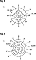
- Figures 3 and 4 show possible configurations of the armature 6 of the valve 1 from FIG Fig. 1 Direction of view marked III, the valve needle 5 being shown as a cut surface for better understanding.
- the end face 22 is divided into partial areas 22A and 22B, between which the spring receptacle 25 is provided.
- through-openings 51 to 54 are provided, which in this embodiment are designed as through-bores 51 to 54 with a circular cross-section.
- kidney-shaped configurations of the through openings 51 to 54 are also realized so that the through openings 51 to 54 extend in a circumferential direction 55 around the longitudinal axis 4 or circumferentially around the longitudinal axis 4 over a larger angular range. In particular, this improves the fuel flow over the shortened length I of the armature 6.
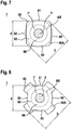
- Figures 5 to 8 show possible configurations of the stop element 7 of the valve 1 contrary to that in FIG Fig. 1 Direction of view designated III, the valve needle 5 being shown in section for illustration.
- a support area 60 for the spring 27 is specified here.
- the support region 60 is delimited radially outward by a line 60A shown in broken lines.
- the support region 60 is delimited radially inward by a line 60l, shown as a broken line.
- the support area 60 serves as the structurally predetermined support area 60 in which the selected spring 27 is intended to be supported.
- the refinements preferably relate to an application in which a guide is implemented between the stop element 7 and the inner pole 3, as for example in FIG Fig. 1 is illustrated.
- depressions 61 to 64 are provided.
- the stop element 7 can proceed from a hollow cylindrical basic shape 65, which is characterized by an outer diameter D. can be modified by such depressions 61 to 64. This results in both the possibility of guidance on the outer diameter D and of a fuel passage through the recesses 61 to 64.
- the recesses 61 to 64 are designed here in such a way that, viewed from the longitudinal axis 4, they extend at most up to a diameter d. This means that an annular surface 66 remains from the valve needle 5 up to the diameter d.
- the diameter d is preferably specified in such a way that it lies between the outer line 60A and the inner line 60l.
- the spring 27 also rests at least partially against the support region 60 in the region of the depressions 61 to 64, namely at least against the annular surface 66. This results in a compromise between good contact between the spring 27 and the support area 60 and the largest possible depressions 61 to 64 and, at the same time, the possibility of guidance on the outer diameter D.
- FIGS. 5 to 8 show different ways of implementing the recesses 61 to 64.
- Fig. 5 as an intersection with cylinder bores
- Fig. 6 as intersections with rectangular cutouts
- Fig. 7 as an intersection with flattened areas.
- the flow cross-section can be formed by ring segments.
Landscapes
- Engineering & Computer Science (AREA)
- Chemical & Material Sciences (AREA)
- Combustion & Propulsion (AREA)
- Mechanical Engineering (AREA)
- General Engineering & Computer Science (AREA)
- Physics & Mathematics (AREA)
- Electromagnetism (AREA)
- Fuel-Injection Apparatus (AREA)
- Magnetically Actuated Valves (AREA)
Priority Applications (1)
| Application Number | Priority Date | Filing Date | Title |
|---|---|---|---|
| EP20209959.4A EP3822475B1 (de) | 2016-12-21 | 2017-10-19 | Ventil zum zumessen eines fluids |
Applications Claiming Priority (2)
| Application Number | Priority Date | Filing Date | Title |
|---|---|---|---|
| DE102016225776.5A DE102016225776A1 (de) | 2016-12-21 | 2016-12-21 | Ventil zum Zumessen eines Fluids |
| PCT/EP2017/076701 WO2018114088A1 (de) | 2016-12-21 | 2017-10-19 | Ventil zum zumessen eines fluids |
Related Child Applications (2)
| Application Number | Title | Priority Date | Filing Date |
|---|---|---|---|
| EP20209959.4A Division EP3822475B1 (de) | 2016-12-21 | 2017-10-19 | Ventil zum zumessen eines fluids |
| EP20209959.4A Division-Into EP3822475B1 (de) | 2016-12-21 | 2017-10-19 | Ventil zum zumessen eines fluids |
Publications (2)
| Publication Number | Publication Date |
|---|---|
| EP3559437A1 EP3559437A1 (de) | 2019-10-30 |
| EP3559437B1 true EP3559437B1 (de) | 2021-01-27 |
Family
ID=60138384
Family Applications (2)
| Application Number | Title | Priority Date | Filing Date |
|---|---|---|---|
| EP17786914.6A Active EP3559437B1 (de) | 2016-12-21 | 2017-10-19 | Ventil zum zumessen eines fluids |
| EP20209959.4A Active EP3822475B1 (de) | 2016-12-21 | 2017-10-19 | Ventil zum zumessen eines fluids |
Family Applications After (1)
| Application Number | Title | Priority Date | Filing Date |
|---|---|---|---|
| EP20209959.4A Active EP3822475B1 (de) | 2016-12-21 | 2017-10-19 | Ventil zum zumessen eines fluids |
Country Status (7)
| Country | Link |
|---|---|
| US (1) | US11359589B2 (ko) |
| EP (2) | EP3559437B1 (ko) |
| JP (1) | JP6845937B2 (ko) |
| KR (1) | KR102394017B1 (ko) |
| CN (1) | CN110100089B9 (ko) |
| DE (1) | DE102016225776A1 (ko) |
| WO (1) | WO2018114088A1 (ko) |
Families Citing this family (4)
| Publication number | Priority date | Publication date | Assignee | Title |
|---|---|---|---|---|
| DE102018218682A1 (de) | 2018-10-31 | 2020-04-30 | Robert Bosch Gmbh | Ventil zum Zumessen eines Fluids |
| DE102018219054A1 (de) | 2018-11-08 | 2020-05-14 | Robert Bosch Gmbh | Ventil zum Zumessen eines Fluids |
| DE102018219543A1 (de) | 2018-11-15 | 2020-05-20 | Robert Bosch Gmbh | Ventil zum Zumessen eines Fluids |
| DE102018222443A1 (de) | 2018-12-20 | 2020-06-25 | Robert Bosch Gmbh | Ventil zum Zumessen eines Fluids |
Family Cites Families (16)
| Publication number | Priority date | Publication date | Assignee | Title |
|---|---|---|---|---|
| US3707992A (en) * | 1970-11-09 | 1973-01-02 | Skinner Precision Ind Inc | Electromagnetic valve assembly |
| US5984210A (en) * | 1997-11-04 | 1999-11-16 | Caterpillar Inc. | Fuel injector utilizing a solenoid having complementarily-shaped dual armatures |
| DE19946602A1 (de) * | 1999-09-29 | 2001-04-12 | Bosch Gmbh Robert | Brennstoffeinspritzventil |
| DE19948238A1 (de) * | 1999-10-07 | 2001-04-19 | Bosch Gmbh Robert | Brennstoffeinspritzventil |
| JP2002357173A (ja) | 2001-03-28 | 2002-12-13 | Denso Corp | 燃料噴射弁の製造方法および燃料噴射弁 |
| DE10133166A1 (de) * | 2001-07-07 | 2003-01-16 | Bosch Gmbh Robert | Kraftstoffeinspritzventil für Brennkraftmaschinen |
| DE10205970A1 (de) * | 2002-02-14 | 2003-09-04 | Bosch Gmbh Robert | Kraftstoffeinspritzventil für Brennkraftmaschinen |
| JP5152024B2 (ja) | 2009-02-04 | 2013-02-27 | 株式会社デンソー | 燃料噴射弁 |
| JP5488120B2 (ja) * | 2010-03-30 | 2014-05-14 | 株式会社デンソー | 燃料噴射弁 |
| US8453951B2 (en) | 2010-09-22 | 2013-06-04 | Delphi Technologies, Inc. | Fuel injector |
| KR101345431B1 (ko) * | 2011-12-09 | 2013-12-27 | 주식회사 현대케피코 | 직분사 연료 인젝터 |
| DE102011090006B4 (de) * | 2011-12-28 | 2015-03-26 | Continental Automotive Gmbh | Ventil |
| DE102013219974B4 (de) | 2013-10-02 | 2019-08-08 | Continental Automotive Gmbh | Ventilbaugruppe für ein Einspritzventil |
| DE102013222613A1 (de) | 2013-11-07 | 2015-05-07 | Robert Bosch Gmbh | Ventil zum Zumessen von Fluid |
| EP3009655B1 (en) * | 2014-10-13 | 2017-08-23 | Continental Automotive GmbH | Fuel injection valve for an internal combustion engine |
| DE102017207270A1 (de) * | 2016-06-30 | 2018-01-04 | Robert Bosch Gmbh | Ventil zum Zumessen eines Fluids |
-
2016
- 2016-12-21 DE DE102016225776.5A patent/DE102016225776A1/de active Pending
-
2017
- 2017-10-19 KR KR1020197017824A patent/KR102394017B1/ko active IP Right Grant
- 2017-10-19 CN CN201780079650.1A patent/CN110100089B9/zh active Active
- 2017-10-19 EP EP17786914.6A patent/EP3559437B1/de active Active
- 2017-10-19 JP JP2019533441A patent/JP6845937B2/ja active Active
- 2017-10-19 EP EP20209959.4A patent/EP3822475B1/de active Active
- 2017-10-19 WO PCT/EP2017/076701 patent/WO2018114088A1/de unknown
- 2017-10-19 US US16/470,831 patent/US11359589B2/en active Active
Non-Patent Citations (1)
| Title |
|---|
| None * |
Also Published As
| Publication number | Publication date |
|---|---|
| KR20190097052A (ko) | 2019-08-20 |
| WO2018114088A1 (de) | 2018-06-28 |
| EP3559437A1 (de) | 2019-10-30 |
| CN110100089A (zh) | 2019-08-06 |
| DE102016225776A1 (de) | 2018-06-21 |
| CN110100089B (zh) | 2021-12-21 |
| EP3822475B1 (de) | 2023-05-17 |
| CN110100089B9 (zh) | 2022-01-11 |
| US20190309712A1 (en) | 2019-10-10 |
| US11359589B2 (en) | 2022-06-14 |
| JP2020502423A (ja) | 2020-01-23 |
| JP6845937B2 (ja) | 2021-03-24 |
| KR102394017B1 (ko) | 2022-05-06 |
| EP3822475A1 (de) | 2021-05-19 |
Similar Documents
| Publication | Publication Date | Title |
|---|---|---|
| EP3559437B1 (de) | Ventil zum zumessen eines fluids | |
| EP3535486B1 (de) | Brennstoffeinspritzventil zum einspritzen eines gasförmigen und/oder flüssigen brennstoffs | |
| EP3478957B1 (de) | Ventil zum eindüsen von gasförmigem kraftstoff | |
| EP2212542B1 (de) | Elektromagnetisch betätigbares ventil | |
| DE19915210A1 (de) | Brennstoffeinspritzventil | |
| DE102016220326A1 (de) | Ventil zum Zumessen eines gasförmigen oder flüssigen Kraftstoffs | |
| DE102014217441A1 (de) | Elektromagnetisch betätigbares Proportionalventil | |
| EP1327065B1 (de) | Magnetventilbetätigtes steuermodul zur fluidkontrolle bei einspritzsystemen | |
| EP3141737B1 (de) | Ventil zum zumessen eines fluids | |
| DE102005046434A1 (de) | Ventilmodul zum Zuführen insbesondere gasförmiger Medien an eine Brennkraftmaschine | |
| EP3034857A1 (de) | Brennstoffeinspritzventil | |
| DE102014225392A1 (de) | Düsenbaugruppe für einen Kraftstoffinjektor sowie Kraftstoffinjektor | |
| EP4033087B1 (de) | Ventil zum zumessen eines fluids | |
| EP2472096A1 (de) | Einspritzventil zum Einspritzen eines Fluids | |
| WO2017008995A1 (de) | Ventil zum zumessen eines fluids | |
| DE10302863B3 (de) | Hydraulischer Koppler für Piezo-Injektoren mit verbesserter Befüllung | |
| DE102019205301A1 (de) | Ventil zum Zumessen eines Fluids | |
| EP3034856B1 (de) | Brennstoffeinspritzventil | |
| DE102007034319A1 (de) | Injektor | |
| WO2019233662A1 (de) | Elektromagnetisch betätigbares saugventil und kraftstoff-hochdruckpumpe | |
| DE102019210614A1 (de) | Ventil zum Zumessen eines Fluids und Brennstoffeinspritzanlage | |
| WO2010108747A1 (de) | Kraftstoffeinspritzvorrichtung | |
| DE102016225769A1 (de) | Ventil zum Zumessen eines Fluids | |
| DE102018215210A1 (de) | Ventil zum Zumessen eines Fluids | |
| EP3423717B1 (de) | Elektromagnetisch betätigbares einlassventil und hochdruckpumpe mit einlassventil |
Legal Events
| Date | Code | Title | Description |
|---|---|---|---|
| STAA | Information on the status of an ep patent application or granted ep patent |
Free format text: STATUS: UNKNOWN |
|
| STAA | Information on the status of an ep patent application or granted ep patent |
Free format text: STATUS: THE INTERNATIONAL PUBLICATION HAS BEEN MADE |
|
| PUAI | Public reference made under article 153(3) epc to a published international application that has entered the european phase |
Free format text: ORIGINAL CODE: 0009012 |
|
| STAA | Information on the status of an ep patent application or granted ep patent |
Free format text: STATUS: REQUEST FOR EXAMINATION WAS MADE |
|
| 17P | Request for examination filed |
Effective date: 20190722 |
|
| AK | Designated contracting states |
Kind code of ref document: A1 Designated state(s): AL AT BE BG CH CY CZ DE DK EE ES FI FR GB GR HR HU IE IS IT LI LT LU LV MC MK MT NL NO PL PT RO RS SE SI SK SM TR |
|
| AX | Request for extension of the european patent |
Extension state: BA ME |
|
| DAV | Request for validation of the european patent (deleted) | ||
| DAX | Request for extension of the european patent (deleted) | ||
| RAP1 | Party data changed (applicant data changed or rights of an application transferred) |
Owner name: ROBERT BOSCH GMBH |
|
| GRAP | Despatch of communication of intention to grant a patent |
Free format text: ORIGINAL CODE: EPIDOSNIGR1 |
|
| STAA | Information on the status of an ep patent application or granted ep patent |
Free format text: STATUS: GRANT OF PATENT IS INTENDED |
|
| INTG | Intention to grant announced |
Effective date: 20200929 |
|
| GRAS | Grant fee paid |
Free format text: ORIGINAL CODE: EPIDOSNIGR3 |
|
| GRAA | (expected) grant |
Free format text: ORIGINAL CODE: 0009210 |
|
| STAA | Information on the status of an ep patent application or granted ep patent |
Free format text: STATUS: THE PATENT HAS BEEN GRANTED |
|
| AK | Designated contracting states |
Kind code of ref document: B1 Designated state(s): AL AT BE BG CH CY CZ DE DK EE ES FI FR GB GR HR HU IE IS IT LI LT LU LV MC MK MT NL NO PL PT RO RS SE SI SK SM TR |
|
| REG | Reference to a national code |
Ref country code: GB Ref legal event code: FG4D Free format text: NOT ENGLISH |
|
| REG | Reference to a national code |
Ref country code: CH Ref legal event code: EP |
|
| REG | Reference to a national code |
Ref country code: AT Ref legal event code: REF Ref document number: 1358563 Country of ref document: AT Kind code of ref document: T Effective date: 20210215 |
|
| REG | Reference to a national code |
Ref country code: IE Ref legal event code: FG4D Free format text: LANGUAGE OF EP DOCUMENT: GERMAN |
|
| REG | Reference to a national code |
Ref country code: DE Ref legal event code: R096 Ref document number: 502017009260 Country of ref document: DE |
|
| REG | Reference to a national code |
Ref country code: NL Ref legal event code: MP Effective date: 20210127 |
|
| REG | Reference to a national code |
Ref country code: LT Ref legal event code: MG9D |
|
| PG25 | Lapsed in a contracting state [announced via postgrant information from national office to epo] |
Ref country code: BG Free format text: LAPSE BECAUSE OF FAILURE TO SUBMIT A TRANSLATION OF THE DESCRIPTION OR TO PAY THE FEE WITHIN THE PRESCRIBED TIME-LIMIT Effective date: 20210427 Ref country code: LT Free format text: LAPSE BECAUSE OF FAILURE TO SUBMIT A TRANSLATION OF THE DESCRIPTION OR TO PAY THE FEE WITHIN THE PRESCRIBED TIME-LIMIT Effective date: 20210127 Ref country code: FI Free format text: LAPSE BECAUSE OF FAILURE TO SUBMIT A TRANSLATION OF THE DESCRIPTION OR TO PAY THE FEE WITHIN THE PRESCRIBED TIME-LIMIT Effective date: 20210127 Ref country code: GR Free format text: LAPSE BECAUSE OF FAILURE TO SUBMIT A TRANSLATION OF THE DESCRIPTION OR TO PAY THE FEE WITHIN THE PRESCRIBED TIME-LIMIT Effective date: 20210428 Ref country code: HR Free format text: LAPSE BECAUSE OF FAILURE TO SUBMIT A TRANSLATION OF THE DESCRIPTION OR TO PAY THE FEE WITHIN THE PRESCRIBED TIME-LIMIT Effective date: 20210127 Ref country code: PT Free format text: LAPSE BECAUSE OF FAILURE TO SUBMIT A TRANSLATION OF THE DESCRIPTION OR TO PAY THE FEE WITHIN THE PRESCRIBED TIME-LIMIT Effective date: 20210527 Ref country code: NO Free format text: LAPSE BECAUSE OF FAILURE TO SUBMIT A TRANSLATION OF THE DESCRIPTION OR TO PAY THE FEE WITHIN THE PRESCRIBED TIME-LIMIT Effective date: 20210427 |
|
| PG25 | Lapsed in a contracting state [announced via postgrant information from national office to epo] |
Ref country code: PL Free format text: LAPSE BECAUSE OF FAILURE TO SUBMIT A TRANSLATION OF THE DESCRIPTION OR TO PAY THE FEE WITHIN THE PRESCRIBED TIME-LIMIT Effective date: 20210127 Ref country code: LV Free format text: LAPSE BECAUSE OF FAILURE TO SUBMIT A TRANSLATION OF THE DESCRIPTION OR TO PAY THE FEE WITHIN THE PRESCRIBED TIME-LIMIT Effective date: 20210127 Ref country code: RS Free format text: LAPSE BECAUSE OF FAILURE TO SUBMIT A TRANSLATION OF THE DESCRIPTION OR TO PAY THE FEE WITHIN THE PRESCRIBED TIME-LIMIT Effective date: 20210127 Ref country code: SE Free format text: LAPSE BECAUSE OF FAILURE TO SUBMIT A TRANSLATION OF THE DESCRIPTION OR TO PAY THE FEE WITHIN THE PRESCRIBED TIME-LIMIT Effective date: 20210127 |
|
| PG25 | Lapsed in a contracting state [announced via postgrant information from national office to epo] |
Ref country code: IS Free format text: LAPSE BECAUSE OF FAILURE TO SUBMIT A TRANSLATION OF THE DESCRIPTION OR TO PAY THE FEE WITHIN THE PRESCRIBED TIME-LIMIT Effective date: 20210527 |
|
| REG | Reference to a national code |
Ref country code: DE Ref legal event code: R097 Ref document number: 502017009260 Country of ref document: DE |
|
| PG25 | Lapsed in a contracting state [announced via postgrant information from national office to epo] |
Ref country code: CZ Free format text: LAPSE BECAUSE OF FAILURE TO SUBMIT A TRANSLATION OF THE DESCRIPTION OR TO PAY THE FEE WITHIN THE PRESCRIBED TIME-LIMIT Effective date: 20210127 Ref country code: EE Free format text: LAPSE BECAUSE OF FAILURE TO SUBMIT A TRANSLATION OF THE DESCRIPTION OR TO PAY THE FEE WITHIN THE PRESCRIBED TIME-LIMIT Effective date: 20210127 Ref country code: SM Free format text: LAPSE BECAUSE OF FAILURE TO SUBMIT A TRANSLATION OF THE DESCRIPTION OR TO PAY THE FEE WITHIN THE PRESCRIBED TIME-LIMIT Effective date: 20210127 |
|
| PG25 | Lapsed in a contracting state [announced via postgrant information from national office to epo] |
Ref country code: RO Free format text: LAPSE BECAUSE OF FAILURE TO SUBMIT A TRANSLATION OF THE DESCRIPTION OR TO PAY THE FEE WITHIN THE PRESCRIBED TIME-LIMIT Effective date: 20210127 Ref country code: DK Free format text: LAPSE BECAUSE OF FAILURE TO SUBMIT A TRANSLATION OF THE DESCRIPTION OR TO PAY THE FEE WITHIN THE PRESCRIBED TIME-LIMIT Effective date: 20210127 Ref country code: SK Free format text: LAPSE BECAUSE OF FAILURE TO SUBMIT A TRANSLATION OF THE DESCRIPTION OR TO PAY THE FEE WITHIN THE PRESCRIBED TIME-LIMIT Effective date: 20210127 |
|
| PLBE | No opposition filed within time limit |
Free format text: ORIGINAL CODE: 0009261 |
|
| STAA | Information on the status of an ep patent application or granted ep patent |
Free format text: STATUS: NO OPPOSITION FILED WITHIN TIME LIMIT |
|
| 26N | No opposition filed |
Effective date: 20211028 |
|
| PG25 | Lapsed in a contracting state [announced via postgrant information from national office to epo] |
Ref country code: AL Free format text: LAPSE BECAUSE OF FAILURE TO SUBMIT A TRANSLATION OF THE DESCRIPTION OR TO PAY THE FEE WITHIN THE PRESCRIBED TIME-LIMIT Effective date: 20210127 Ref country code: ES Free format text: LAPSE BECAUSE OF FAILURE TO SUBMIT A TRANSLATION OF THE DESCRIPTION OR TO PAY THE FEE WITHIN THE PRESCRIBED TIME-LIMIT Effective date: 20210127 |
|
| PG25 | Lapsed in a contracting state [announced via postgrant information from national office to epo] |
Ref country code: SI Free format text: LAPSE BECAUSE OF FAILURE TO SUBMIT A TRANSLATION OF THE DESCRIPTION OR TO PAY THE FEE WITHIN THE PRESCRIBED TIME-LIMIT Effective date: 20210127 |
|
| REG | Reference to a national code |
Ref country code: CH Ref legal event code: PL |
|
| PG25 | Lapsed in a contracting state [announced via postgrant information from national office to epo] |
Ref country code: IS Free format text: LAPSE BECAUSE OF FAILURE TO SUBMIT A TRANSLATION OF THE DESCRIPTION OR TO PAY THE FEE WITHIN THE PRESCRIBED TIME-LIMIT Effective date: 20210527 |
|
| REG | Reference to a national code |
Ref country code: BE Ref legal event code: MM Effective date: 20211031 |
|
| GBPC | Gb: european patent ceased through non-payment of renewal fee |
Effective date: 20211019 |
|
| PG25 | Lapsed in a contracting state [announced via postgrant information from national office to epo] |
Ref country code: MC Free format text: LAPSE BECAUSE OF FAILURE TO SUBMIT A TRANSLATION OF THE DESCRIPTION OR TO PAY THE FEE WITHIN THE PRESCRIBED TIME-LIMIT Effective date: 20210127 |
|
| PG25 | Lapsed in a contracting state [announced via postgrant information from national office to epo] |
Ref country code: LU Free format text: LAPSE BECAUSE OF NON-PAYMENT OF DUE FEES Effective date: 20211019 Ref country code: GB Free format text: LAPSE BECAUSE OF NON-PAYMENT OF DUE FEES Effective date: 20211019 Ref country code: BE Free format text: LAPSE BECAUSE OF NON-PAYMENT OF DUE FEES Effective date: 20211031 |
|
| PG25 | Lapsed in a contracting state [announced via postgrant information from national office to epo] |
Ref country code: LI Free format text: LAPSE BECAUSE OF NON-PAYMENT OF DUE FEES Effective date: 20211031 Ref country code: CH Free format text: LAPSE BECAUSE OF NON-PAYMENT OF DUE FEES Effective date: 20211031 |
|
| PG25 | Lapsed in a contracting state [announced via postgrant information from national office to epo] |
Ref country code: IE Free format text: LAPSE BECAUSE OF NON-PAYMENT OF DUE FEES Effective date: 20211019 |
|
| P01 | Opt-out of the competence of the unified patent court (upc) registered |
Effective date: 20230509 |
|
| PG25 | Lapsed in a contracting state [announced via postgrant information from national office to epo] |
Ref country code: NL Free format text: LAPSE BECAUSE OF NON-PAYMENT OF DUE FEES Effective date: 20210127 Ref country code: CY Free format text: LAPSE BECAUSE OF FAILURE TO SUBMIT A TRANSLATION OF THE DESCRIPTION OR TO PAY THE FEE WITHIN THE PRESCRIBED TIME-LIMIT Effective date: 20210127 |
|
| PG25 | Lapsed in a contracting state [announced via postgrant information from national office to epo] |
Ref country code: HU Free format text: LAPSE BECAUSE OF FAILURE TO SUBMIT A TRANSLATION OF THE DESCRIPTION OR TO PAY THE FEE WITHIN THE PRESCRIBED TIME-LIMIT; INVALID AB INITIO Effective date: 20171019 |
|
| REG | Reference to a national code |
Ref country code: AT Ref legal event code: MM01 Ref document number: 1358563 Country of ref document: AT Kind code of ref document: T Effective date: 20221019 |
|
| PG25 | Lapsed in a contracting state [announced via postgrant information from national office to epo] |
Ref country code: AT Free format text: LAPSE BECAUSE OF NON-PAYMENT OF DUE FEES Effective date: 20221019 |
|
| PGFP | Annual fee paid to national office [announced via postgrant information from national office to epo] |
Ref country code: IT Payment date: 20231031 Year of fee payment: 7 Ref country code: FR Payment date: 20231023 Year of fee payment: 7 |
|
| PG25 | Lapsed in a contracting state [announced via postgrant information from national office to epo] |
Ref country code: MK Free format text: LAPSE BECAUSE OF FAILURE TO SUBMIT A TRANSLATION OF THE DESCRIPTION OR TO PAY THE FEE WITHIN THE PRESCRIBED TIME-LIMIT Effective date: 20210127 |
|
| PGFP | Annual fee paid to national office [announced via postgrant information from national office to epo] |
Ref country code: DE Payment date: 20231218 Year of fee payment: 7 |