EP3558825B1 - Zigarettenmagazin für eine zigarettenverpackungsmaschine sowie verfahren zum betreiben desselben - Google Patents
Zigarettenmagazin für eine zigarettenverpackungsmaschine sowie verfahren zum betreiben desselben Download PDFInfo
- Publication number
- EP3558825B1 EP3558825B1 EP17829126.6A EP17829126A EP3558825B1 EP 3558825 B1 EP3558825 B1 EP 3558825B1 EP 17829126 A EP17829126 A EP 17829126A EP 3558825 B1 EP3558825 B1 EP 3558825B1
- Authority
- EP
- European Patent Office
- Prior art keywords
- vibration
- shaft
- vibration generator
- cigarette
- vibrations
- Prior art date
- Legal status (The legal status is an assumption and is not a legal conclusion. Google has not performed a legal analysis and makes no representation as to the accuracy of the status listed.)
- Active
Links
Images



Classifications
-
- B—PERFORMING OPERATIONS; TRANSPORTING
- B65—CONVEYING; PACKING; STORING; HANDLING THIN OR FILAMENTARY MATERIAL
- B65B—MACHINES, APPARATUS OR DEVICES FOR, OR METHODS OF, PACKAGING ARTICLES OR MATERIALS; UNPACKING
- B65B19/00—Packaging rod-shaped or tubular articles susceptible to damage by abrasion or pressure, e.g. cigarettes, cigars, macaroni, spaghetti, drinking straws or welding electrodes
- B65B19/02—Packaging cigarettes
- B65B19/04—Arranging, feeding, or orientating the cigarettes
-
- A—HUMAN NECESSITIES
- A24—TOBACCO; CIGARS; CIGARETTES; SIMULATED SMOKING DEVICES; SMOKERS' REQUISITES
- A24C—MACHINES FOR MAKING CIGARS OR CIGARETTES
- A24C5/00—Making cigarettes; Making tipping materials for, or attaching filters or mouthpieces to, cigars or cigarettes
- A24C5/35—Adaptations of conveying apparatus for transporting cigarettes from making machine to packaging machine
-
- A—HUMAN NECESSITIES
- A24—TOBACCO; CIGARS; CIGARETTES; SIMULATED SMOKING DEVICES; SMOKERS' REQUISITES
- A24C—MACHINES FOR MAKING CIGARS OR CIGARETTES
- A24C5/00—Making cigarettes; Making tipping materials for, or attaching filters or mouthpieces to, cigars or cigarettes
- A24C5/35—Adaptations of conveying apparatus for transporting cigarettes from making machine to packaging machine
- A24C5/352—Adaptations of conveying apparatus for transporting cigarettes from making machine to packaging machine using containers, i.e. boats
- A24C5/356—Emptying the boats into the hopper of the packaging machine
-
- B—PERFORMING OPERATIONS; TRANSPORTING
- B65—CONVEYING; PACKING; STORING; HANDLING THIN OR FILAMENTARY MATERIAL
- B65B—MACHINES, APPARATUS OR DEVICES FOR, OR METHODS OF, PACKAGING ARTICLES OR MATERIALS; UNPACKING
- B65B35/00—Supplying, feeding, arranging or orientating articles to be packaged
- B65B35/30—Arranging and feeding articles in groups
- B65B35/32—Arranging and feeding articles in groups by gravity
-
- B—PERFORMING OPERATIONS; TRANSPORTING
- B65—CONVEYING; PACKING; STORING; HANDLING THIN OR FILAMENTARY MATERIAL
- B65B—MACHINES, APPARATUS OR DEVICES FOR, OR METHODS OF, PACKAGING ARTICLES OR MATERIALS; UNPACKING
- B65B35/00—Supplying, feeding, arranging or orientating articles to be packaged
- B65B35/30—Arranging and feeding articles in groups
- B65B35/34—Arranging and feeding articles in groups by agitators or vibrators
-
- B—PERFORMING OPERATIONS; TRANSPORTING
- B65—CONVEYING; PACKING; STORING; HANDLING THIN OR FILAMENTARY MATERIAL
- B65B—MACHINES, APPARATUS OR DEVICES FOR, OR METHODS OF, PACKAGING ARTICLES OR MATERIALS; UNPACKING
- B65B35/00—Supplying, feeding, arranging or orientating articles to be packaged
- B65B35/30—Arranging and feeding articles in groups
- B65B35/54—Feeding articles along multiple paths to a single packaging position
-
- B—PERFORMING OPERATIONS; TRANSPORTING
- B65—CONVEYING; PACKING; STORING; HANDLING THIN OR FILAMENTARY MATERIAL
- B65B—MACHINES, APPARATUS OR DEVICES FOR, OR METHODS OF, PACKAGING ARTICLES OR MATERIALS; UNPACKING
- B65B57/00—Automatic control, checking, warning, or safety devices
-
- B—PERFORMING OPERATIONS; TRANSPORTING
- B65—CONVEYING; PACKING; STORING; HANDLING THIN OR FILAMENTARY MATERIAL
- B65B—MACHINES, APPARATUS OR DEVICES FOR, OR METHODS OF, PACKAGING ARTICLES OR MATERIALS; UNPACKING
- B65B57/00—Automatic control, checking, warning, or safety devices
- B65B57/02—Automatic control, checking, warning, or safety devices responsive to absence, presence, abnormal feed, or misplacement of binding or wrapping material, containers, or packages
- B65B57/04—Automatic control, checking, warning, or safety devices responsive to absence, presence, abnormal feed, or misplacement of binding or wrapping material, containers, or packages and operating to control, or to stop, the feed of such material, containers, or packages
-
- B—PERFORMING OPERATIONS; TRANSPORTING
- B65—CONVEYING; PACKING; STORING; HANDLING THIN OR FILAMENTARY MATERIAL
- B65B—MACHINES, APPARATUS OR DEVICES FOR, OR METHODS OF, PACKAGING ARTICLES OR MATERIALS; UNPACKING
- B65B2210/00—Specific aspects of the packaging machine
- B65B2210/10—Means for removing bridges formed by the material or article, e.g. anti-clogging devices
Definitions
- the present invention relates to a cigarette magazine in connection with or for a cigarette packaging machine with one or more groups of shafts, each with several shafts arranged next to one another and each delimited by shaft walls, along which cigarettes can be conveyed by their own weight essentially parallel to the shaft walls. Furthermore, the invention relates to a method for operating such a magazine.
- Cigarette magazines are part of the standard equipment of a cigarette packaging machine.
- a cigarette magazine usually consists of an upper storage container for the cigarettes and a group of upright or slightly inclined shafts adjoining the underside of the same. The shafts are separated from each other by thin shaft walls. You regularly have a distance from each other that is only slightly larger than the diameter of a cigarette.
- the cigarettes are filled continuously or in batches into the storage container via a filling opening. Within the same, the cigarettes lie closely side by side in a parallel and regularly horizontal orientation. The cigarettes then move from the reservoir into the shafts due to the force of gravity or as a result of their own weight, with a row of cigarettes arranged one above the other being formed in each shaft.
- the cigarettes are then placed on the underside of the shafts Groups or taken as a formation.
- Each several horizontal rows of cigarettes - regularly up to three on top of each other - are pushed out of the shafts in the longitudinal direction of the cigarettes to form a cigarette group corresponding to the contents of a cigarette pack.
- Vibration of the packaging machine or other reasons can cause tobacco to come loose, particularly from the front area of individual cigarettes, as the cigarettes move downwards in the shafts.
- the tobacco crumbs can then become lodged in the respective shaft and prevent the cigarettes from moving further down the shaft. This can result in the desired cigarette formation being ejected incompletely, out of position, or incorrectly, resulting in faulty production.
- Cigarette magazines and devices for arranging cigarettes are also known, in which one or more shaft walls of a shaft are also moved by moving an element on which they are at least partially arranged.
- a cigarette magazine in which several or all shaft walls of each shaft group, namely the end faces of the shaft walls, are operatively connected to at least one common, movable, in particular freely oscillating vibration plate in such a way that the vibrations of the plate are transmitted to the shaft walls during operation, and wherein the vibrating plate has a back wall of the cigarette magazine, which closes the shafts in some areas or completely, in particular their open rear ends, characterized in that at least one (in particular the upper) area of the rear wall is fastened or can be fastened to a stationary storage device, preferably by means of screws, and the vibration generator for Transmission of the vibrations is operatively connected to at least one other free (unfixed) area of the rear wall, which is preferably at a distance from the aforementioned area (in particular arranged further down), in particular an end area which, by at least partially elastic deformation of the rear wall relative to the fixed rear wall area and is movable.
- the vibrating plate is therefore movably mounted in that the rear wall is only fixed in a preferably narrow area while the other areas remain unfixed and can therefore be moved in the aforementioned manner relative to the fixed area.
- the vibrating plate can be vibrated in a targeted manner using an (electrically or pneumatically operated) vibration generator.
- the vibration plate is preferably connected to the shaft walls in a non-positive and/or positive manner, for example screwed to them.
- the vibration plate can be part of a superordinate component of any form.
- the vibrations can be initiated precisely where they are to achieve the greatest effect, for example to prevent or resolve blockages in the conveyor of the cigarettes caused by tobacco crumbs, namely directly on the shaft walls or the shafts.
- the shafts of the shaft groups are expediently upright in a manner known per se, if necessary with a (slight) inclination to the vertical in particular in sections, with the distances between the shaft walls being chosen such that in each shaft accommodates a row of cigarettes arranged one on top of the other.
- the cigarette magazine usually has a storage container for cigarettes, to which the shafts of the shaft group(s) connect below.
- the depth of a shaft often corresponds approximately to the length of a cigarette. So that the cigarettes cannot slide out of the shafts at the front or rear, the end faces on both sides of the shafts can be partially or completely closed by a front or rear wall. Only one side can be closed.
- the vibration plate forms such a rear wall which is connected (for example screwed) to the shaft walls (in particular to their respective rear end faces) in a non-positive and/or positive manner.
- This rear wall can correspondingly partially or completely close the shafts, in particular their corresponding (rear) open end faces.
- the vibrating plate can also extend over the entire width and height of all groups of shafts, so that the shafts are completely closed by the vibrating plate at their respective end faces.
- one vibrating plate can also be assigned to only one group of shafts and close their shafts or the end faces mentioned in the manner described, either completely or in certain areas.
- the vibrations can also occur perpendicularly to the shaft walls within the plane of the plate, ie ultimately perpendicularly to the longitudinal extension of the cigarettes.
- Vibration movements within the plane of the plate namely parallel to the shaft walls, are also conceivable (regular up and down movements in the vertical) or vibration movements in the plane of the plate, which are circular or elliptical. Combinations or superimpositions of such movements can also be useful.
- each shaft group of the cigarette magazine (see above) is assigned at least one vibration plate of its own.
- the vibration plates can be connected to one another, for example by at least one connecting means, such as a connecting web, so that they vibrate at the same frequency when subjected to vibrations by a vibration generator assigned to them or operatively connected to them.
- At least two vibration plates are assigned a common vibration generator, which is connected to them in particular in a non-positive and/or positive manner, so that the vibration generator simultaneously forms the connecting means.
- a vibration generator is preferably assigned to two adjacent vibration plates or arranged on them, so that it transmits vibrations generated by it to both vibration plates.
- All the vibration plates are preferably connected to one another so that they vibrate at the same frequency after being excited by at least one vibration generator.
- the at least one vibrating plate or, as a rule, all the vibrating plates are expediently movably mounted on a (common) stationary bearing element, in particular on a stationary bearing plate. Namely in such a way that the respective vibration plate can vibrate relative to the stationary bearing element.
- elastic bearing means for example rubber buffers or the like, can be provided which are connected on the one hand to the bearing element and on the other hand to the vibration plate.
- At least two groups of shafts or at least two different areas of a group of shafts are each assigned separate, in particular unconnected, vibration plates and vibration generators.
- the two vibrating plates and with them the two shaft groups or the two different shaft group areas can be vibrated independently of one another, so that they can also vibrate with different frequencies, phases and/or amplitudes etc.
- the upper area could be subjected to vibrations in a different direction, different amplitude, different frequency and/or different phase, etc than the lower area.
- This can be useful if only because the wall thicknesses of the shaft walls generally decrease from top to bottom thus there are larger oscillating masses in the lower area than in the upper area.
- there are different oscillation systems with correspondingly different resonant frequencies which can lead to problems if the oscillations or vibrations are not designed appropriately in each case.
- the two or at least two vibration generators are preferably arranged or operatively connected to the assigned area of the group of shafts and/or designed in such a way that the vibration movements of the vibration plate assigned to one vibration generator take place or can take place at an angle to the vibration movements of the vibration plate assigned to the other vibration generator .
- the fixed bearing device to which the rear wall is fixed or fastened in the said area, it can be, for example, a (stationary) housing or it can comprise such.
- the vibration generator comprises at least one spring part, in particular an elongate one, preferably at least two spring parts, in particular a spring steel sheet, with the (possibly respective) spring part having a first fastening area, which is fastened to the free area of the rear wall, and a second Fastening area that is mounted in a stationary manner or is fastened to a stationary bearing device, with a movement transmission element of the vibration generator, which is moved in particular by an (electric) motor-driven eccentric shaft and preferably executes vertical up and down movements, being operatively connected to the spring part between the two fastening areas.
- the first attachment area and the second attachment area can be opposite end areas of the spring part, with the movement transmission member being attached to the spring part preferably essentially centrally between these two end areas.
- vertical up and down movements of the movement transmission element can lead to up and down movements of the spring part in an area between the first and second fastening area of the spring part, which in turn cause back and forth movements or vibration movements of the rear wall.
- the movement transmission member can be a connecting rod connected to the eccentric shaft, the eccentric shaft preferably being driven by a (servo)motor, in particular a speed-controlled one.
- the solution according to the invention to the above-mentioned object according to claim 9 is characterized in that the frequency and/or the amplitude and/or the phases of the vibrations or oscillations generated by the at least one vibration generator are periodically and repeatedly changed during operation of the cigarette magazine.
- Tobacco crumbs or the like suitable or appropriate vibrations / oscillations can be initiated, which can resolve the respective blockage.
- a vibration generator can be used at least temporarily with a different frequency and/or amplitude and/or or phase than the other vibration generator.
- a first vibration generator could be operated with a constant frequency, a second with a periodically changing frequency.
- the respective chute group to be set vibrating could have different actual masses, which lead to a different, particularly undesirable vibration or oscillation behavior of the respective chute group.
- the actual vibrations of the respective group of chutes generated by the respective vibration generator are automatically measured (preferably several times, in particular continuously or at predetermined time intervals) with a sensor, for example with a particular acceleration sensor arranged on the respective shaft group, and then to automatically control/regulate the vibration generator depending on the measurement result.
- one or more operating parameters or control parameters of the vibration generator (such as phase, frequency and/or amplitude) would then be set/changed automatically in accordance with the measurements of the respective actual vibrations or oscillations of the respective group of shafts or the shaft walls of the same .
- Whether such a fault is present could possibly be recognized by means of suitable test measurements. For example, in that the actual vibrations of the ducts or possibly groups of ducts are recorded in the manner indicated above. If the actual vibrations deviate to a certain extent from the target vibrations, this can indicate a malfunction or an error. Alternatively, a wide variety of other types of test measurements are conceivable in order to determine such a fault directly or indirectly.
- the vibrations or the oscillations that the vibration generator generates are changed automatically after a fault has been determined until the fault has been eliminated.
- further test measurements are preferably carried out subsequently, in particular continuously or periodically.
- the parameter values of the frequency and/or the amplitude and/or the phase of the vibrations or the vibrations generated by the vibration generator could be selected or changed automatically depending on the type of cigarettes with which the magazine is filled or is to be filled, so that at least one different parameter value is set for a first type of cigarette than for a second type of cigarette that differs from the first.
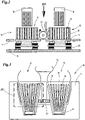
- the Figures 1-8 show a cigarette magazine 10 as can be used, for example, in a cigarette packaging machine known per se.
- a reservoir not shown, in which a large number of cigarettes 11 is accommodated.
- Such a reservoir is usually filled through an upper opening.
- Guide elements 12 are arranged within the storage container, which direct the cigarettes 11 to two shaft groups 13 arranged below the storage container.
- the cigarettes lie parallel to one another and aligned horizontally, with the cigarette ends of all cigarettes 11 ideally lying essentially in a common vertical plane.
- Each shaft group 13 has several shafts 14, in the present case seven. As a result of gravity, the cigarettes 11 slide out of the storage container into the shafts 14, with a row of cigarettes 11 arranged one above the other being accommodated in each shaft 14.
- the shafts 14 are each delimited laterally by (upright) shaft walls 15.
- the distance between the shaft walls 15 is chosen so that essentially only one cigarette fits horizontally or horizontally in each shaft 14, ie not several next to each other.
- the shafts 14 and the shaft walls 15 of a group of shafts 13 usually run at a slight angle to one another, namely at a distance from one another that increases downwards.
- the width of the shaft walls 15 decreases from top to bottom. But this does not have to be the case.
- each shaft 14 essentially corresponds to the length of a cigarette. However, it can also be (slightly) larger or smaller.
- the cigarettes 11 are grouped or pushed out in groups by a pusher 16 according to the formation of cigarettes 11 to be received from a cigarette pack.
- the vibrating plate 18 of each shaft group 13 is fixed, in this case non-positively, to the shaft group 13 of the same, for example screwed.
- Each vibration plate 18 is movably mounted using bearing means 20 on a stationary bearing element 19, in this case a stationary support plate.
- the bearing means 20 can be or comprise elastic buffers, such as rubber buffers or the like, which interact with rear fastening strips of the vibration plate 18.
- the only decisive factor is that the respective vibration plate 18 can move in one or more directions relative to the stationary bearing element 19 .
- the vibration plates 18 can be made to vibrate or oscillate by means of a pneumatically or electrically operated, controllable vibration generator 21 (vibrator). Vibration generators 21 of this type are known, so that their designs will not be discussed in any more detail here.
- the vibration generator 21 is arranged on the two vibration plates 18 or is (operatively) connected to them in a non-positive and/or positive manner, cf. 2 , so that it can cause both vibration plates 18 to oscillate or vibrate at the same time during operation.
- one section of the vibration generator 21 is connected to one vibration plate 18 and another section to the other vibration plate 18.
- the vibrating plates 18 on the other hand - as explained above - are connected in a non-positive and/or positive manner to the respective shaft walls 15 of the associated group of shafts 13, during operation of the vibration generator 21 the vibrations of the latter are first transmitted to the vibrating plates 18 and then directly to the shaft walls 15 transfer.
- shaft walls 15 in multiple parts (here in two parts) to form a common (in particular horizontal) transport channel 23 running at an angle to the shaft walls 15 .
- the individual shafts 14 are each connected individually to the transport channel 23 .
- Loosened tobacco crumbs can then move out of the respective shafts along the transport channel 23 with the aid of the vibrations introduced according to the invention, in particular horizontally outwards, see also Figures 6, 7 .
- Vibration movements are particularly preferably introduced perpendicularly to the plane of the vibration plate, so that the shaft walls 15 are moved back and forth in the longitudinal direction of the cigarettes 11 or in the horizontal direction.
- vibrations can also be generated in the plane of the plate, which are circular or elliptical, cf. 4 .
- an alternative storage or Suspension of the vibration plates 18 required, as exemplified in the embodiments of Figures 4 and 5 is shown in sketch form (omitting the bearing elements on which the bearing means 20 are supported).
- the upper diagram in 8 to recognize that in the standard case, the one or more vibrating plates 18 can be applied with a uniform frequency and uniform amplitude.
- the 9 , 10 show a further embodiment 10' of a cigarette magazine according to the invention. Identical or similar components are provided with the same reference numbers as in the cigarette magazine 10 described above - insofar as they match.
- the shaft walls 15 are each directly connected to a vibrating plate 18, respectively.
- the vibrating plate 18 extends along all shaft groups 13 or shafts 14 and correspondingly forms the rear wall for all shaft groups 13 or shafts 14. End faces of all shaft walls 15 are connected to the vibration plate 18.
- the cigarette magazine 10' differs from the cigarette magazine 10 in particular by the type of movable mounting of the vibration plate 18, the type of generation of the vibrations and the type of transmission of the same to the vibration plate 18.
- the vibration plate 18 is firmly connected to a stationary bearing device 24 in an upper (narrow) (end) area.
- the vibration plate 18 has upper, lateral fastening sections 25a, b on two opposite, spaced sides, which are each integrally connected to a main part 26 of the vibration plate 18 via a narrow connecting region 27a or 27b or connecting web.
- the fastening sections 25a, b are each firmly connected or fixed to the bearing device 24 by means of fastening means 28, here screws, namely in the present case on vertical housing parts 29a, 29b of the cigarette magazine 10'.
- the vibration plate 18 In the lower area of the vibration plate 18 or the main part 26 thereof, the vibration plate 18 is not fixed, but designed to be freely suspended. As a result, an at least regionally elastic deformation of the lower area of the vibration plate 18 relative to the fixed upper area is possible. In the present example, about a horizontal axis of rotation, which runs in the upper area of the vibration plate 18 approximately at the height of the fastening sections 25a, b.
- the vibrating plate 18 can therefore, with appropriate excitation by a vibration generator 21', carry out back and forth movements in a vertical plane running perpendicular to the horizontal axis of rotation. In 9 the movements running on a curved path are carried out in a direction almost perpendicular to the plane of the image.
- the vibration generator 21' is designed in a special way to generate these movements.
- It comprises a (speed-controlled) servo motor 31 which drives a revolving shaft 32 which extends along the vibrating plate 18 at a distance and parallel thereto in a horizontal plane.
- the shaft 32 is rotatably mounted on the bearing device 24 or on the housing parts 29a, b by means of rotary bearings 33a, b.
- the shaft 32 is an eccentric shaft which is connected to movement transmission elements 34a, b, namely connecting rods or connecting rods in the present case.
- the movement-transmitting members 34a, b each perform back and forth movements, namely up and down movements in a vertical plane, cf. 10 .
- Each movement transmission element 34a, b is fastened (here by means of a clamp) to a spring part 30a or 30b.
- the spring parts 30a, b are designed as spring (steel) sheets.
- Each spring part 30a, b has a first fastening area 35 which is connected to the vibration plate 18 or is fastened to it (here by means of a clamp).
- the first fastening area 35 is at the same time a first end area of the respective spring part 30a, b.
- each spring part 30a, b has a second fastening region 37, in this case an end region of the respective spring part 30a, b which is opposite the first end region and is mounted in a stationary manner. In each case on a stationary bearing part 36a, b or a cross support of the bearing device 24.
- the respective movement transmission element 34a, b is attached (essentially) centrally to the respective spring part 30a, b.
- the servo motor 31 drives the shaft 32, as a result of which the motion transmission members 34a,b are moved up and down.
- a subsequent upward movement of the movement transmission element 34a, b leads to a backward movement of the vibration plate 18 into the image plane.
Landscapes
- Engineering & Computer Science (AREA)
- Mechanical Engineering (AREA)
- Manufacturing Of Cigar And Cigarette Tobacco (AREA)
- Wrapping Of Specific Fragile Articles (AREA)
Applications Claiming Priority (2)
| Application Number | Priority Date | Filing Date | Title |
|---|---|---|---|
| DE102016015539.6A DE102016015539A1 (de) | 2016-12-21 | 2016-12-21 | Zigarettenmagazin für eine Zigarettenverpackungsmaschine sowie Verfahren zum Betreiben desselben |
| PCT/EP2017/001431 WO2018114042A1 (de) | 2016-12-21 | 2017-12-19 | Zigarettenmagazin für eine zigarettenverpackungsmaschine sowie verfahren zum betreiben desselben |
Publications (2)
| Publication Number | Publication Date |
|---|---|
| EP3558825A1 EP3558825A1 (de) | 2019-10-30 |
| EP3558825B1 true EP3558825B1 (de) | 2022-05-11 |
Family
ID=60972166
Family Applications (1)
| Application Number | Title | Priority Date | Filing Date |
|---|---|---|---|
| EP17829126.6A Active EP3558825B1 (de) | 2016-12-21 | 2017-12-19 | Zigarettenmagazin für eine zigarettenverpackungsmaschine sowie verfahren zum betreiben desselben |
Country Status (6)
| Country | Link |
|---|---|
| EP (1) | EP3558825B1 (pl) |
| CN (1) | CN110087998B (pl) |
| DE (1) | DE102016015539A1 (pl) |
| HU (1) | HUE059366T2 (pl) |
| PL (1) | PL3558825T3 (pl) |
| WO (1) | WO2018114042A1 (pl) |
Families Citing this family (6)
| Publication number | Priority date | Publication date | Assignee | Title |
|---|---|---|---|---|
| EP3772289B1 (en) * | 2019-08-05 | 2023-03-01 | International Tobacco Machinery Poland SP. Z O.O. | A feeding apparatus for feeding single-layer stream of tobacco industry's rod-like articles |
| CN110844162A (zh) * | 2019-11-19 | 2020-02-28 | 河南中烟工业有限责任公司 | 一种硬盒卷烟包装机的小盒开边检测装置 |
| CN111232281A (zh) * | 2020-03-03 | 2020-06-05 | 上海烟草机械有限责任公司 | 组合双烟支香烟的包装设备及包装方法 |
| CN112471589B (zh) * | 2020-11-12 | 2022-07-26 | 河南中烟工业有限责任公司 | 一种二号轮内衬纸纠偏方法和纠偏装置及内衬纸包裹系统 |
| CN113665873B (zh) * | 2021-06-25 | 2025-02-25 | 云南远足科技有限公司 | 一种用于将烟支放入成型烟盒的包装机及其包装方法 |
| CN114655495A (zh) * | 2022-04-29 | 2022-06-24 | 河南中烟工业有限责任公司 | 一种盒烟包装用的自动装料机 |
Citations (1)
| Publication number | Priority date | Publication date | Assignee | Title |
|---|---|---|---|---|
| DE1014921B (de) * | 1955-05-06 | 1957-08-29 | Niepmann & Co Maschf Fr | Vorrichtung zum Zufuehren und Ordnen von Zigaretten |
Family Cites Families (8)
| Publication number | Priority date | Publication date | Assignee | Title |
|---|---|---|---|---|
| DE513997C (de) * | 1929-04-24 | 1930-12-05 | Muller J C & Co | Vorrichtung zum Ordnen von Zigaretten |
| GB340883A (en) * | 1929-07-20 | 1931-01-08 | Muller J C & Co | Improvements in apparatus for feeding cigarettes from hoppers or like receptacles to packeting machines |
| GB775826A (en) * | 1954-10-01 | 1957-05-29 | Korber Kurt | Improvements in supply hoppers for cigarettes and similar rod-like articles |
| DE955755C (de) * | 1954-10-02 | 1957-01-10 | Kurt Koerber & Co K G | Behaelter zur Entnahme von stabfoermigem Gut, insbesondere Zigaretten, Zigarillos od. dgl. |
| DE1104424B (de) | 1959-12-22 | 1961-04-06 | Tabak & Ind Masch | Vorrichtung zum Zufuehren von Zigaretten aus einem Vorratsbehaelter zwischen die Magazintrennwaende einer Zigarettenpackmaschine |
| DE2545891C2 (de) * | 1975-10-14 | 1984-04-26 | Efka-Werke Fritz Kiehn Gmbh, 7218 Trossingen | Schacht-Abfüllvorrichtung für Filterzigaretten-Hülsen |
| CN1007418B (zh) * | 1985-04-24 | 1990-04-04 | 福克有限公司 | 包装细长的制品特别是包装卷烟用的装置 |
| IT1266280B1 (it) * | 1993-03-05 | 1996-12-27 | Gd Spa | Tramoggia per elementi allungati,in particolare articoli da fumo. |
-
2016
- 2016-12-21 DE DE102016015539.6A patent/DE102016015539A1/de not_active Withdrawn
-
2017
- 2017-12-19 EP EP17829126.6A patent/EP3558825B1/de active Active
- 2017-12-19 PL PL17829126.6T patent/PL3558825T3/pl unknown
- 2017-12-19 WO PCT/EP2017/001431 patent/WO2018114042A1/de not_active Ceased
- 2017-12-19 HU HUE17829126A patent/HUE059366T2/hu unknown
- 2017-12-19 CN CN201780079380.4A patent/CN110087998B/zh active Active
Patent Citations (1)
| Publication number | Priority date | Publication date | Assignee | Title |
|---|---|---|---|---|
| DE1014921B (de) * | 1955-05-06 | 1957-08-29 | Niepmann & Co Maschf Fr | Vorrichtung zum Zufuehren und Ordnen von Zigaretten |
Also Published As
| Publication number | Publication date |
|---|---|
| CN110087998B (zh) | 2022-03-01 |
| DE102016015539A1 (de) | 2018-06-21 |
| PL3558825T3 (pl) | 2022-09-26 |
| EP3558825A1 (de) | 2019-10-30 |
| HUE059366T2 (hu) | 2022-11-28 |
| WO2018114042A1 (de) | 2018-06-28 |
| CN110087998A (zh) | 2019-08-02 |
Similar Documents
| Publication | Publication Date | Title |
|---|---|---|
| EP3558825A1 (de) | Zigarettenmagazin für eine zigarettenverpackungsmaschine sowie verfahren zum betreiben desselben | |
| DE102019204845B3 (de) | Vorrichtung und Verfahren zum Einstellen und Regeln wenigstens einer Schwingungsmode mittels der Vielzahl von Unwuchterregereinheiten an einer Siebvorrichtung | |
| EP2003074B1 (de) | Vorrichtung zur Förderung und zum Sortieren von Tabletten | |
| DE2502943C2 (de) | Verteilungsvorrichtung zur Förderung von Schüttgut von einer Vorratsquelle zu mehreren Verbraucherstellen | |
| EP2896583B1 (de) | Vibrationszuführsystem | |
| EP3774603B1 (de) | Vibrationsförderer | |
| EP2910312A1 (de) | Schwinganordnung für einen Rütteltisch oder eine Siebvorrichtung | |
| DE2136279B2 (de) | Vibratorhalterung | |
| DE102012206347B4 (de) | Siebvorrichtung | |
| DE202014008855U1 (de) | Siebmaschine mit Antrieb | |
| EP3532410A2 (de) | Vibrationsförderer | |
| EP3746231B1 (de) | Siebvorrichtung | |
| DE2255071C2 (de) | Vibrationsvorrichtung | |
| DE4407305A1 (de) | Trichter für langgestreckte Teile, insbesondere Rauchwaren | |
| EP3114053B1 (de) | Maschine zur vereinzelung von elementen | |
| EP1460006B1 (de) | Vibrations-Linearförderer | |
| EP2633924A1 (de) | Spannwellensieb | |
| EP1165259A1 (de) | Sortiervorrichtung | |
| WO2022179715A1 (de) | Vibrationsförderer und anordnung zum fördern eines flächigen werkstücks, insbesondere eines blechs sowie positioniervorrichtung mit einem vibrationsförderer zur positionierung eines flächigen werkstücks | |
| DE102008000892A1 (de) | Zuführsystem für Kleinteile | |
| DE102022100143B4 (de) | Schwingmaschine sowie Verfahren zum Betreiben einer Schwingmaschine | |
| DE102022108307B3 (de) | Schwingmaschine sowie Verfahren zum Betreiben der Schwingmaschine | |
| EP3018058B1 (de) | Füllvorrichtung für Blisterbahnen | |
| EP3917690B1 (de) | Schwingsiebanlage, bestehend aus wenigstens zwei in reihe angeordneten siebmaschinen | |
| DE3043009A1 (de) | Ein- oder mehrkomponenten-schwingzufuehrungssystem |
Legal Events
| Date | Code | Title | Description |
|---|---|---|---|
| STAA | Information on the status of an ep patent application or granted ep patent |
Free format text: STATUS: UNKNOWN |
|
| STAA | Information on the status of an ep patent application or granted ep patent |
Free format text: STATUS: THE INTERNATIONAL PUBLICATION HAS BEEN MADE |
|
| PUAI | Public reference made under article 153(3) epc to a published international application that has entered the european phase |
Free format text: ORIGINAL CODE: 0009012 |
|
| STAA | Information on the status of an ep patent application or granted ep patent |
Free format text: STATUS: REQUEST FOR EXAMINATION WAS MADE |
|
| 17P | Request for examination filed |
Effective date: 20190619 |
|
| AK | Designated contracting states |
Kind code of ref document: A1 Designated state(s): AL AT BE BG CH CY CZ DE DK EE ES FI FR GB GR HR HU IE IS IT LI LT LU LV MC MK MT NL NO PL PT RO RS SE SI SK SM TR |
|
| AX | Request for extension of the european patent |
Extension state: BA ME |
|
| TPAC | Observations filed by third parties |
Free format text: ORIGINAL CODE: EPIDOSNTIPA |
|
| DAV | Request for validation of the european patent (deleted) | ||
| DAX | Request for extension of the european patent (deleted) | ||
| STAA | Information on the status of an ep patent application or granted ep patent |
Free format text: STATUS: EXAMINATION IS IN PROGRESS |
|
| 17Q | First examination report despatched |
Effective date: 20200518 |
|
| RIC1 | Information provided on ipc code assigned before grant |
Ipc: A24C 5/35 20060101ALI20210909BHEP Ipc: B65B 35/32 20060101ALI20210909BHEP Ipc: B65B 35/34 20060101ALI20210909BHEP Ipc: B65B 35/54 20060101ALI20210909BHEP Ipc: B65B 57/04 20060101ALI20210909BHEP Ipc: B65B 57/00 20060101ALI20210909BHEP Ipc: B65B 59/00 20060101ALI20210909BHEP Ipc: A24C 5/32 20060101ALI20210909BHEP Ipc: A24C 5/356 20060101ALI20210909BHEP Ipc: B65B 19/04 20060101AFI20210909BHEP |
|
| GRAP | Despatch of communication of intention to grant a patent |
Free format text: ORIGINAL CODE: EPIDOSNIGR1 |
|
| STAA | Information on the status of an ep patent application or granted ep patent |
Free format text: STATUS: GRANT OF PATENT IS INTENDED |
|
| INTG | Intention to grant announced |
Effective date: 20211123 |
|
| GRAS | Grant fee paid |
Free format text: ORIGINAL CODE: EPIDOSNIGR3 |
|
| GRAA | (expected) grant |
Free format text: ORIGINAL CODE: 0009210 |
|
| STAA | Information on the status of an ep patent application or granted ep patent |
Free format text: STATUS: THE PATENT HAS BEEN GRANTED |
|
| AK | Designated contracting states |
Kind code of ref document: B1 Designated state(s): AL AT BE BG CH CY CZ DE DK EE ES FI FR GB GR HR HU IE IS IT LI LT LU LV MC MK MT NL NO PL PT RO RS SE SI SK SM TR |
|
| REG | Reference to a national code |
Ref country code: GB Ref legal event code: FG4D Free format text: NOT ENGLISH |
|
| REG | Reference to a national code |
Ref country code: CH Ref legal event code: EP |
|
| REG | Reference to a national code |
Ref country code: AT Ref legal event code: REF Ref document number: 1491240 Country of ref document: AT Kind code of ref document: T Effective date: 20220515 |
|
| REG | Reference to a national code |
Ref country code: DE Ref legal event code: R096 Ref document number: 502017013187 Country of ref document: DE |
|
| REG | Reference to a national code |
Ref country code: IE Ref legal event code: FG4D Free format text: LANGUAGE OF EP DOCUMENT: GERMAN |
|
| REG | Reference to a national code |
Ref country code: RO Ref legal event code: EPE |
|
| REG | Reference to a national code |
Ref country code: LT Ref legal event code: MG9D |
|
| REG | Reference to a national code |
Ref country code: NL Ref legal event code: MP Effective date: 20220511 |
|
| REG | Reference to a national code |
Ref country code: GR Ref legal event code: EP Ref document number: 20220401562 Country of ref document: GR Effective date: 20221010 |
|
| PG25 | Lapsed in a contracting state [announced via postgrant information from national office to epo] |
Ref country code: SE Free format text: LAPSE BECAUSE OF FAILURE TO SUBMIT A TRANSLATION OF THE DESCRIPTION OR TO PAY THE FEE WITHIN THE PRESCRIBED TIME-LIMIT Effective date: 20220511 Ref country code: PT Free format text: LAPSE BECAUSE OF FAILURE TO SUBMIT A TRANSLATION OF THE DESCRIPTION OR TO PAY THE FEE WITHIN THE PRESCRIBED TIME-LIMIT Effective date: 20220912 Ref country code: NO Free format text: LAPSE BECAUSE OF FAILURE TO SUBMIT A TRANSLATION OF THE DESCRIPTION OR TO PAY THE FEE WITHIN THE PRESCRIBED TIME-LIMIT Effective date: 20220811 Ref country code: NL Free format text: LAPSE BECAUSE OF FAILURE TO SUBMIT A TRANSLATION OF THE DESCRIPTION OR TO PAY THE FEE WITHIN THE PRESCRIBED TIME-LIMIT Effective date: 20220511 Ref country code: LT Free format text: LAPSE BECAUSE OF FAILURE TO SUBMIT A TRANSLATION OF THE DESCRIPTION OR TO PAY THE FEE WITHIN THE PRESCRIBED TIME-LIMIT Effective date: 20220511 Ref country code: HR Free format text: LAPSE BECAUSE OF FAILURE TO SUBMIT A TRANSLATION OF THE DESCRIPTION OR TO PAY THE FEE WITHIN THE PRESCRIBED TIME-LIMIT Effective date: 20220511 Ref country code: FI Free format text: LAPSE BECAUSE OF FAILURE TO SUBMIT A TRANSLATION OF THE DESCRIPTION OR TO PAY THE FEE WITHIN THE PRESCRIBED TIME-LIMIT Effective date: 20220511 Ref country code: ES Free format text: LAPSE BECAUSE OF FAILURE TO SUBMIT A TRANSLATION OF THE DESCRIPTION OR TO PAY THE FEE WITHIN THE PRESCRIBED TIME-LIMIT Effective date: 20220511 Ref country code: BG Free format text: LAPSE BECAUSE OF FAILURE TO SUBMIT A TRANSLATION OF THE DESCRIPTION OR TO PAY THE FEE WITHIN THE PRESCRIBED TIME-LIMIT Effective date: 20220811 |
|
| REG | Reference to a national code |
Ref country code: HU Ref legal event code: AG4A Ref document number: E059366 Country of ref document: HU |
|
| PG25 | Lapsed in a contracting state [announced via postgrant information from national office to epo] |
Ref country code: RS Free format text: LAPSE BECAUSE OF FAILURE TO SUBMIT A TRANSLATION OF THE DESCRIPTION OR TO PAY THE FEE WITHIN THE PRESCRIBED TIME-LIMIT Effective date: 20220511 Ref country code: LV Free format text: LAPSE BECAUSE OF FAILURE TO SUBMIT A TRANSLATION OF THE DESCRIPTION OR TO PAY THE FEE WITHIN THE PRESCRIBED TIME-LIMIT Effective date: 20220511 Ref country code: IS Free format text: LAPSE BECAUSE OF FAILURE TO SUBMIT A TRANSLATION OF THE DESCRIPTION OR TO PAY THE FEE WITHIN THE PRESCRIBED TIME-LIMIT Effective date: 20220911 |
|
| PG25 | Lapsed in a contracting state [announced via postgrant information from national office to epo] |
Ref country code: SM Free format text: LAPSE BECAUSE OF FAILURE TO SUBMIT A TRANSLATION OF THE DESCRIPTION OR TO PAY THE FEE WITHIN THE PRESCRIBED TIME-LIMIT Effective date: 20220511 Ref country code: SK Free format text: LAPSE BECAUSE OF FAILURE TO SUBMIT A TRANSLATION OF THE DESCRIPTION OR TO PAY THE FEE WITHIN THE PRESCRIBED TIME-LIMIT Effective date: 20220511 Ref country code: EE Free format text: LAPSE BECAUSE OF FAILURE TO SUBMIT A TRANSLATION OF THE DESCRIPTION OR TO PAY THE FEE WITHIN THE PRESCRIBED TIME-LIMIT Effective date: 20220511 Ref country code: DK Free format text: LAPSE BECAUSE OF FAILURE TO SUBMIT A TRANSLATION OF THE DESCRIPTION OR TO PAY THE FEE WITHIN THE PRESCRIBED TIME-LIMIT Effective date: 20220511 Ref country code: CZ Free format text: LAPSE BECAUSE OF FAILURE TO SUBMIT A TRANSLATION OF THE DESCRIPTION OR TO PAY THE FEE WITHIN THE PRESCRIBED TIME-LIMIT Effective date: 20220511 |
|
| REG | Reference to a national code |
Ref country code: DE Ref legal event code: R097 Ref document number: 502017013187 Country of ref document: DE |
|
| PGFP | Annual fee paid to national office [announced via postgrant information from national office to epo] |
Ref country code: HU Payment date: 20221205 Year of fee payment: 6 |
|
| PLBE | No opposition filed within time limit |
Free format text: ORIGINAL CODE: 0009261 |
|
| STAA | Information on the status of an ep patent application or granted ep patent |
Free format text: STATUS: NO OPPOSITION FILED WITHIN TIME LIMIT |
|
| PG25 | Lapsed in a contracting state [announced via postgrant information from national office to epo] |
Ref country code: AL Free format text: LAPSE BECAUSE OF FAILURE TO SUBMIT A TRANSLATION OF THE DESCRIPTION OR TO PAY THE FEE WITHIN THE PRESCRIBED TIME-LIMIT Effective date: 20220511 |
|
| 26N | No opposition filed |
Effective date: 20230214 |
|
| PG25 | Lapsed in a contracting state [announced via postgrant information from national office to epo] |
Ref country code: SI Free format text: LAPSE BECAUSE OF FAILURE TO SUBMIT A TRANSLATION OF THE DESCRIPTION OR TO PAY THE FEE WITHIN THE PRESCRIBED TIME-LIMIT Effective date: 20220511 |
|
| P01 | Opt-out of the competence of the unified patent court (upc) registered |
Effective date: 20230517 |
|
| REG | Reference to a national code |
Ref country code: CH Ref legal event code: PL |
|
| GBPC | Gb: european patent ceased through non-payment of renewal fee |
Effective date: 20221219 |
|
| REG | Reference to a national code |
Ref country code: BE Ref legal event code: MM Effective date: 20221231 |
|
| PG25 | Lapsed in a contracting state [announced via postgrant information from national office to epo] |
Ref country code: LU Free format text: LAPSE BECAUSE OF NON-PAYMENT OF DUE FEES Effective date: 20221219 |
|
| PG25 | Lapsed in a contracting state [announced via postgrant information from national office to epo] |
Ref country code: LI Free format text: LAPSE BECAUSE OF NON-PAYMENT OF DUE FEES Effective date: 20221231 Ref country code: IE Free format text: LAPSE BECAUSE OF NON-PAYMENT OF DUE FEES Effective date: 20221219 Ref country code: GB Free format text: LAPSE BECAUSE OF NON-PAYMENT OF DUE FEES Effective date: 20221219 Ref country code: CH Free format text: LAPSE BECAUSE OF NON-PAYMENT OF DUE FEES Effective date: 20221231 |
|
| PG25 | Lapsed in a contracting state [announced via postgrant information from national office to epo] |
Ref country code: FR Free format text: LAPSE BECAUSE OF NON-PAYMENT OF DUE FEES Effective date: 20221231 Ref country code: BE Free format text: LAPSE BECAUSE OF NON-PAYMENT OF DUE FEES Effective date: 20221231 |
|
| REG | Reference to a national code |
Ref country code: AT Ref legal event code: MM01 Ref document number: 1491240 Country of ref document: AT Kind code of ref document: T Effective date: 20221219 |
|
| PG25 | Lapsed in a contracting state [announced via postgrant information from national office to epo] |
Ref country code: AT Free format text: LAPSE BECAUSE OF NON-PAYMENT OF DUE FEES Effective date: 20221219 |
|
| PG25 | Lapsed in a contracting state [announced via postgrant information from national office to epo] |
Ref country code: CY Free format text: LAPSE BECAUSE OF FAILURE TO SUBMIT A TRANSLATION OF THE DESCRIPTION OR TO PAY THE FEE WITHIN THE PRESCRIBED TIME-LIMIT Effective date: 20220511 Ref country code: AT Free format text: LAPSE BECAUSE OF NON-PAYMENT OF DUE FEES Effective date: 20221219 |
|
| PG25 | Lapsed in a contracting state [announced via postgrant information from national office to epo] |
Ref country code: MK Free format text: LAPSE BECAUSE OF FAILURE TO SUBMIT A TRANSLATION OF THE DESCRIPTION OR TO PAY THE FEE WITHIN THE PRESCRIBED TIME-LIMIT Effective date: 20220511 |
|
| PG25 | Lapsed in a contracting state [announced via postgrant information from national office to epo] |
Ref country code: MC Free format text: LAPSE BECAUSE OF FAILURE TO SUBMIT A TRANSLATION OF THE DESCRIPTION OR TO PAY THE FEE WITHIN THE PRESCRIBED TIME-LIMIT Effective date: 20220511 |
|
| PG25 | Lapsed in a contracting state [announced via postgrant information from national office to epo] |
Ref country code: TR Free format text: LAPSE BECAUSE OF FAILURE TO SUBMIT A TRANSLATION OF THE DESCRIPTION OR TO PAY THE FEE WITHIN THE PRESCRIBED TIME-LIMIT Effective date: 20220511 Ref country code: MC Free format text: LAPSE BECAUSE OF FAILURE TO SUBMIT A TRANSLATION OF THE DESCRIPTION OR TO PAY THE FEE WITHIN THE PRESCRIBED TIME-LIMIT Effective date: 20220511 |
|
| PG25 | Lapsed in a contracting state [announced via postgrant information from national office to epo] |
Ref country code: MT Free format text: LAPSE BECAUSE OF FAILURE TO SUBMIT A TRANSLATION OF THE DESCRIPTION OR TO PAY THE FEE WITHIN THE PRESCRIBED TIME-LIMIT Effective date: 20220511 |
|
| PG25 | Lapsed in a contracting state [announced via postgrant information from national office to epo] |
Ref country code: HU Free format text: LAPSE BECAUSE OF NON-PAYMENT OF DUE FEES Effective date: 20231220 |
|
| PG25 | Lapsed in a contracting state [announced via postgrant information from national office to epo] |
Ref country code: HU Free format text: LAPSE BECAUSE OF NON-PAYMENT OF DUE FEES Effective date: 20231220 |
|
| PG25 | Lapsed in a contracting state [announced via postgrant information from national office to epo] |
Ref country code: BG Free format text: LAPSE BECAUSE OF FAILURE TO SUBMIT A TRANSLATION OF THE DESCRIPTION OR TO PAY THE FEE WITHIN THE PRESCRIBED TIME-LIMIT Effective date: 20220511 |
|
| PG25 | Lapsed in a contracting state [announced via postgrant information from national office to epo] |
Ref country code: BG Free format text: LAPSE BECAUSE OF FAILURE TO SUBMIT A TRANSLATION OF THE DESCRIPTION OR TO PAY THE FEE WITHIN THE PRESCRIBED TIME-LIMIT Effective date: 20220511 |
|
| PGFP | Annual fee paid to national office [announced via postgrant information from national office to epo] |
Ref country code: DE Payment date: 20251127 Year of fee payment: 9 |
|
| PGFP | Annual fee paid to national office [announced via postgrant information from national office to epo] |
Ref country code: GR Payment date: 20251215 Year of fee payment: 9 |
|
| PGFP | Annual fee paid to national office [announced via postgrant information from national office to epo] |
Ref country code: PL Payment date: 20251208 Year of fee payment: 9 |
|
| PGFP | Annual fee paid to national office [announced via postgrant information from national office to epo] |
Ref country code: RO Payment date: 20251218 Year of fee payment: 9 |
|
| PGFP | Annual fee paid to national office [announced via postgrant information from national office to epo] |
Ref country code: IT Payment date: 20251231 Year of fee payment: 9 |