EP3558730B1 - Anordnung für ein visier eines fahrzeuges - Google Patents
Anordnung für ein visier eines fahrzeuges Download PDFInfo
- Publication number
- EP3558730B1 EP3558730B1 EP17885250.5A EP17885250A EP3558730B1 EP 3558730 B1 EP3558730 B1 EP 3558730B1 EP 17885250 A EP17885250 A EP 17885250A EP 3558730 B1 EP3558730 B1 EP 3558730B1
- Authority
- EP
- European Patent Office
- Prior art keywords
- visor
- vehicle
- arrangement
- diffuser portions
- upper portion
- Prior art date
- Legal status (The legal status is an assumption and is not a legal conclusion. Google has not performed a legal analysis and makes no representation as to the accuracy of the status listed.)
- Active
Links
Images

Classifications
-
- B—PERFORMING OPERATIONS; TRANSPORTING
- B60—VEHICLES IN GENERAL
- B60J—WINDOWS, WINDSCREENS, NON-FIXED ROOFS, DOORS, OR SIMILAR DEVICES FOR VEHICLES; REMOVABLE EXTERNAL PROTECTIVE COVERINGS SPECIALLY ADAPTED FOR VEHICLES
- B60J3/00—Antiglare equipment associated with windows or windscreens; Sun visors for vehicles
- B60J3/002—External sun shield, e.g. awning or visor
-
- B—PERFORMING OPERATIONS; TRANSPORTING
- B62—LAND VEHICLES FOR TRAVELLING OTHERWISE THAN ON RAILS
- B62D—MOTOR VEHICLES; TRAILERS
- B62D35/00—Vehicle bodies characterised by streamlining
- B62D35/001—For commercial vehicles or tractor-trailer combinations, e.g. caravans
-
- B—PERFORMING OPERATIONS; TRANSPORTING
- B60—VEHICLES IN GENERAL
- B60Y—INDEXING SCHEME RELATING TO ASPECTS CROSS-CUTTING VEHICLE TECHNOLOGY
- B60Y2306/00—Other features of vehicle sub-units
- B60Y2306/09—Reducing noise
Definitions
- the invention relates to an arrangement for a visor of a vehicle according to the preamble of claim 1.
- the invention also relates to a vehicle.
- Sun visors are arranged externally at an upper portion of a vehicle in connection to the windshield of the vehicle for providing a shaded area upon the windshield of the vehicle.
- US5836640 discloses a sun visor mounted on the windshield of a truck where air holes are arranged in order to reduce turbulence and thereby also reduce created noise.
- An object of the present invention is to provide an arrangement for a visor of a vehicle which facilitates efficient noise reduction with low air resistance.
- an object of the invention is achieved by an arrangement with a visor of a vehicle.
- Said visor has a front side arranged to face away from the vehicle and a rear side facing the vehicle.
- Said visor is arranged to be mounted on an upper portion of the vehicle in connection to the windshield of the vehicle such that air is allowed to flow past said visor sides and thus between the visor and the vehicle.
- Said arrangement comprises means for reducing noise caused by said flow of air.
- said means for reducing noise comprises a set of diffuser portions arranged along at least one of said visor sides so as to create an incoherence of said flow of air and consequently a noise reduction.
- a visor with efficient noise reduction and low air resistance is obtained.
- Such a set of diffuser portions arranged at a side of said visor affects a coherent air flow which may be caused by essentially parallel sides with even surfaces, such coherent air flow on occasions creating noise such as a whistling noise, the diffuser portions creating an incoherence of the air flow reducing the noise and essentially eliminating possible whistling noise.
- Such a set of diffuser portions may easily be applied to an existing visor, thus facilitating a cost efficient solution for reducing noise without essentially affecting air resistance of such an existing visor.
- Said visor is configured to provide a shaded area upon the windshield of the vehicle when mounted.
- said set of diffuser portions are arranged along said rear side of said visor.
- said set of diffuser portions are arranged along an upper portion of said rear side of said visor.
- said set of diffuser portions are arranged along an upper portion of said rear side of said visor.
- At least some of said diffuser portions are arranged at different distances relative to each other along said visor.
- At least some of said diffuser portions have different shapes compared to each other.
- said set of diffuser portions comprises diffuser portions being recesses in a visor side.
- said recesses are upwardly open.
- At least some of said recesses are arranged at different distances relative to each other along said visor.
- At least some of said recesses have different shapes compared to each other.
- At least some of said recesses have an upwardly widening configuration.
- At least some of said recesses have upwardly widening side walls.
- Each side wall has according to an embodiment an angle relative to the vertical plane relative to the vertical plane.
- the total angle of the side walls is according to an embodiment in the range of 5 to 30 degrees, preferably in the range of 10-20 degrees.
- said set of diffuser portions comprises diffuser portions being protrusions on a visor side.
- said protrusions are arranged such that the space between said protrusion is upwardly open.
- At least some of said protrusions are arranged at different distances relative to each other along said visor.
- efficient incoherence of the flow of air and thus efficient noise reduction may be obtained.
- At least some of said protrusions have different shapes compared to each other. Hereby efficient incoherence of the flow of air and thus efficient noise reduction may be obtained.
- At least some of said protrusions have an upwardly widening configuration.
- efficient incoherence of the flow of air and thus efficient noise reduction may be obtained.
- said visor has a comparatively even thickness in the range of 1 up to several centimetres, and wherein said diffuser portions have dimensions in comparatively the same range and wherein the distance between the respective diffuser portions are in comparatively the same range.
- a visor comprising an arrangement a set out herein, said visor being configured to be arranged on a vehicle, said visor having a front side arranged to face away from the vehicle and a rear side facing the vehicle, said visor being arranged to be mounted on an upper portion of the vehicle in connection to the windshield of the vehicle such that air is allowed to flow past said visor sides and thus between the visor and the vehicle.
- the visor comprises an arrangement according to the invention comprising the above mentioned embodiments.
- a vehicle comprising an arrangement as set out herein.
- visor refers to any suitable unit configured to be mounted to an upper portion of the vehicle in connection to the windshield of the vehicle and configured to provide a shaded area upon the windshield during sunshine in order to reduce the disturbance of sun for the driver and possible passenger of the vehicle.
- visor may also be denoted sun visor or windshield visor or sun protection device.
- the term "diffusor portion” refers to any irregularity which when arranged along at least one of the sides of an element with two opposite sides such as a visor where air is allowed to flow past said opposite sides, e.g. visor sides, creates an incoherence of said flow of air and thereby reduces possible noise caused by said flow of air.
- Fig. 1a schematically illustrates a side view of a vehicle 1 according to the present invention.
- the exemplified vehicle 1 is a heavy vehicle in the shape of a truck.
- the vehicle according to the present invention could be any suitable vehicle such as a truck, a bus or a car.
- the vehicle 1 has a cab 2 with an upper portion 2a.
- the vehicle has a windshield 3.
- the windshield 3 is arranged at the front side of the cab 2.
- Said upper portion 2a of the cab 2 thus constitutes an upper portion 2a of the vehicle arranged in connection to the windshield 3.
- the vehicle 1 comprises a visor 10 mounted on an upper portion of the vehicle 1 in connection to the windshield 3 of the vehicle 1.
- the visor 10 is thus arranged in connection to said upper portion 2a of the cab 2.
- the visor 10 is configured to provide a shaded area upon the windshield 3 of the vehicle 1.
- Fig. 1b schematically illustrates a detail I of the vehicle in fig. 1a with the visor 10 according to an embodiment of the present invention.
- the visor 10 has a front side 10a arranged to face away from the vehicle 1 and a rear side 10b facing the vehicle 1.
- the visor 10 is mounted on said upper portion 2a of the vehicle 1 in connection to the windshield 3 of the vehicle 1 such that flow of air F is allowed to flow past said visor sides 10a, 10b and thus between the visor 10 and the vehicle 1.
- a an air portion F1 of the flow of air F is allowed to pass on the front side 10a of the visor 10 and a portion F2 of the flow of air F is allowed to pass on the rear side 10b of the visor 10.
- the visor 10 is thus arranged to be mounted in connection to said upper portion 2a so that at least a portion of said rear side 10b of the visor is arranged at a distance from a portion 2a1 of the upper portion 2a so that said portion F2 of the air flow is allowed to pass there between.
- Fig. 2 schematically illustrates a perspective view of a visor 10 applied to an upper portion 2a of a vehicle 1 with an arrangement A1 according to an embodiment of the present invention
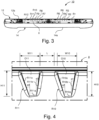
- fig. 3 schematically illustrates a rear view of the visor in fig. 2
- fig. 4 schematically illustrates a rear view of a pair of diffuser portions of the visor in fig. 3
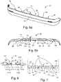
- fig. 5a schematically illustrates a perspective view of the visor in fig. 2
- fig. 5b schematically illustrates a plan view of the visor in fig. 2 .
- the vehicle 1, here the cab 2 of the vehicle has an upper portion 2a and right and left side portions 2b, 2c.
- the vehicle 1, i.e. the cab 2 of the vehicle 1, has a windshield 3.
- the visor 10 has an elongated shape.
- the visor 10 is mounted on said upper portion 2a of the vehicle 1 in connection to the windshield 3 of the vehicle 1.
- the visor 10 is mounted on said upper portion 2a so that the main direction of extension of the elongated visor 10 is transversal relative to the longitudinal extension of the vehicle 1.
- the visor 10 is thus transversely arranged in connection to said upper portion 2a of the cab 2.
- the visor 10 is configured to provide a shaded area upon the windshield 3 of the vehicle 1.
- the visor 10 has an upper mounting part 12 configured to be mounted to the vehicle 1, here the cab 2 of the vehicle 1 and hence the upper portion 2a of the vehicle 1.
- the visor further comprises a lower shading part 14 connectable to said upper part 12 and arranged to provide a shaded area upon the windshield 3 in the mounted state of the visor 10.
- the lower shading part 14 of the visor may be connected to the upper mounting part 12 with any suitable fastening means.
- the lower shading part 14 of the visor is according to an embodiment connectable to the upper mounting part 12 with a snap joint arrangement. According to an alternative embodiment the lower shading part constitutes an integrated portion of the visor 10.
- Said upper mounting part 12 of the visor 10 has an upper portion 12a.
- the visor 10 has a front side 10a arranged to face away from the vehicle 1 and a rear side 10b facing the vehicle 1 as described also with reference to fig. 1b .
- the visor 10 is mounted on said upper portion 2a of the vehicle 1 in connection to the windshield 3 of the vehicle 1 such that flow of air is allowed to flow past said visor sides 10a, 10b and thus between the visor 10 and the vehicle 1, as schematically illustrated in fig. 1b .
- the visor 10 is thus arranged to be mounted in connection to said upper portion 2a so that at least a portion of said rear side 10b of the visor is arranged at a distance from a portion of the upper portion 2a so that a portion of the air flow is allowed to pass there between, as illustrated in fig. 1b .
- the visor 10 is arranged to be mounted via three fastening members 22, 24, 26 arranged at a distance from each other in the lateral direction of the vehicle 10.
- Said fastening members 22, 24, 26 comprises a right fastening member 22 arranged in connection to a right portion of said upper portion 2a of the cab 2, an intermediate fastening member 24 arranged in connection to an intermediate portion of said upper portion 2a of the cab 2, and a left fastening member 26 arranged in connection to a left portion of said upper portion 2a of the cab 2. Said flow of air is thus allowed to flow between said right fastening member 22 and said intermediate fastening member 24 and between said left fastening member 26 and said intermediate fastening member 24.
- Said fastening members 22, 24, 26 may be any suitable fastening members for attaching said visor to said upper portion 2a of the cab 2.
- Said fastening members 22, 24, 26 may comprises screw joints attached to said upper portion 2a.
- Each fastening member 22, 24, 26 comprises according to an embodiment a support member arranged to abut a portion of the upper portion 2a for supporting the visor 10.
- the vehicle comprises an arrangement A1 for said visor 10.
- Said arrangement A1 comprises means for reducing noise caused by said flow of air allowed to flow past said visor sides 10a, 10b and thus between the visor 10 and a portion of said upper portion 2a.
- Said means for reducing noise comprises a set D1 of diffuser portions arranged along said rear side 10b of said visor 10 so as to create an incoherence of said flow of air and consequently a noise reduction.
- said set D1 of diffuser portions are arranged along the rear side 10b of the visor 10. Said set D1 of diffuser portions are arranged along an upper portion 12a of said rear side of said visor 10. Said set D1 of diffuser portions are arranged along said upper portion 12a of said mounting part 12, on the rear side of said visor 10.
- Said set D1 of diffuser portions are described in more detail below with reference to fig. 3a-b, 4a-b, 5 and 6.
- Said set D1 of diffuser portions are arranged between said right fastening member 22 and said intermediate fastening member 24 and between said left fastening member 26 and said intermediate fastening member 24.
- said set D1 of diffuser portions comprises diffuser portions being recesses R1, R2, R3, R4, R5, R6, R7, R8, R9, R10, R11, R12, hereinafter denoted R1-R12, in the rear visor side 10b as seen e.g. in fig. 3 and fig. 5b .
- said set D1 of diffuser portions comprises a set of recesses R1-R12.
- Said set R1-R12 of recesses are arranged along the upper portion 12a of said rear side of said visor 10, and thus along said upper portion 12a of said mounting part 12, on the rear side of said visor 10 as illustrated in fig. 3 .
- Said set of recesses R1-R12 are arranged with a set of recesses R1-R6 between said right fastening member 22 and said intermediate fastening member 24 and a set of recesses R7-R12 between said left fastening member 26 and said intermediate fastening member 24 as illustrated in fig. 5b .
- Said set of recesses R1-R12 are upwardly open, see e.g. fig. 3 .
- Fig. 4 schematically illustrates a rear view of a pair of diffuser portions of the visor 10 in fig. 3 ; and fig. 6 schematically illustrates a plan view of the same pair of diffuser portions of the visor in fig. 5b .
- fig. 4 schematically illustrates a rear view of a pair of recesses R10, R11 of the visor 10
- fig. 6 schematically illustrates a plan view of the same recesses R10, R11 of the visor 10.
- said recess R10 is upwardly open with an opening O10 and said recess R11 is upwardly open with an opening O11.
- said recesses R10, R11 have an upwardly widening configuration.
- Said recess R10 has a bottom portion R10a, see fig. 4 , opposite side walls R10b, R10c as seen in fig. 4 and fig. 6 , and a rear wall R10d as seen in fig. 6 .
- the side wall R10b has an angle ⁇ 1 relative to the vertical plane and the side wall R10c has an angle ⁇ 2 relative to the vertical plane.
- the total angle ⁇ 1+ ⁇ 2 may be any suitable angle.
- the total angle ⁇ 1+ ⁇ 2 is according to an embodiment in the range of 5 to 30 degrees, preferably in the range of 10-20 degrees.
- Said rear wall R10d is upwardly widening.
- the rear wall R10d has an angle ⁇ 1 relative to the vertical plane in connection to the side wall R10b and an angle ⁇ 2 relative to the vertical plane in connection to the side wall R10c.
- the angles ⁇ 1 and ⁇ 2 are according to an embodiment essentially the same.
- the angles ⁇ 1 and ⁇ 2 may be any suitable angle.
- the side wall R11b has an angle ⁇ 3 relative to the vertical plane and the side wall R11c has an angle ⁇ 4 relative to the vertical plane.
- the total angle ⁇ 3+ ⁇ 4 may be any suitable angle.
- the total angle ⁇ 3+ ⁇ 4 is according to an embodiment in the range of 5 to 30 degrees, preferably in the range of 10-20 degrees.
- Said rear wall R11d is upwardly widening.
- the rear wall R11d has an angle ⁇ 3 relative to the vertical plane in connection to the side wall R11b and an angle ⁇ 4 relative to the vertical plane in connection to the side wall R11c.
- the angles ⁇ 3and ⁇ 4 are according to an embodiment essentially the same.
- the angles ⁇ 3 and ⁇ 4 may be any suitable angle.
- Said recesses R10, R11 are arranged at a distance L from each other. According to this embodiment of the arrangement A1 at least some of said recesses R1-R12 are arranged at different distances relative to each other along said visor 10.
- said visor 10 has a comparatively even thickness T1 in the range of centimetres, see fig. 5b .
- Said recesses R1-R12 have dimensions in comparatively the same range and the distance between the respective recess are in comparatively the same range.
- Said recesses R1-R12 have a depth in the vertical direction, i.e. height, in comparatively the same range as the thickness T1 of the visor 10. As shown in fig. 4 the recess R10 has a height H10 and the recess R11 has a height H11, both in the range of a few centimetres.
- Said recesses R1-R12 have a width in connection to the opening in comparatively the same range as the thickness T1 of the visor 10. As shown in fig. 4 the recess R10 has a width W10 and the recess R11 has a width W11, both in the range of a few centimetres.
- Said recesses R1-R12 have a depth in the horizontal direction in comparatively the same range as the thickness T1 of the visor 10, here about a third of the thickness T1 of the visor 10.
- the recess R10 has a depth D10 and the recess R11 has a depth D11, both in the range of a few centimetres.
- the depth D10, D11 is smaller than the width W10, W11 and the height H10, H11.
- Fig. 7 schematically illustrates a plan view of a visor 110 applied to an upper portion 2a of a vehicle with an arrangement A2 not part of the present invention.
- the vehicle may be any suitable vehicle, e.g. the vehicle described with reference to fig. 1a .
- the visor 110 has an elongated shape.
- the visor 110 is mounted on said upper portion 2a of the vehicle 1 in connection to the windshield of the vehicle 1.
- the visor 110 is mounted on said upper portion 2a so that the main direction of extension of the elongated visor 110 is transversal relative to the longitudinal extension of the vehicle.
- the visor 110 has a front side 110a arranged to face away from the vehicle and hence the upper portion 2a and a rear side 110b facing the vehicle and hence the upper portion 2a.
- the visor 110 is mounted on said upper portion 2a of the vehicle in connection to the windshield of the vehicle such that flow of air is allowed to flow past said visor sides 110a, 110b and thus between the visor 110 and the vehicle and hence the upper portion 2a, i.e. a portion of the upper portion 2a.
- the visor 110 is thus arranged to be mounted in connection to said upper portion 2a so that at least a portion of said rear side 110b of the visor is arranged at a distance from a portion of the upper portion 2a so that a portion of the air flow is allowed to pass there between.
- the visor 110 is arranged to be mounted via fastening members 122, 124 arranged at a distance from each other in the lateral direction of the vehicle. Said flow of air is allowed to flow between said right fastening members 122, 124.
- Said fastening members 122, 124 may be any suitable fastening members for attaching said visor to said upper portion 2a.
- Said fastening members 122, 124 may comprises screw joints attached to said upper portion 2a.
- Each fastening member 122, 124 comprises according to an embodiment a support member arranged to abut a portion of the upper portion 2a for supporting the visor 110.
- the vehicle comprises an arrangement A2 for said visor 110.
- Said arrangement A2 comprises means for reducing noise caused by said flow of air allowed to flow past said visor sides 110a, 110b and thus between the visor 110 and a portion of said upper portion 2a.
- Said means for reducing noise comprises a set D2 of diffuser portions arranged along said rear side 110b of said visor 110 so as to create an incoherence of said flow of air and consequently a noise reduction.
- said set D2 of diffuser portions are arranged along the rear side 110b of the visor 110.
- Said set D2 of diffuser portions are arranged along an upper portion of said rear side of said visor 110.
- Said set D2 of diffuser portions are arranged between said fastening members 122, 124.
- said set D2 of diffuser portions comprises diffuser portions being protrusions P1, P2, P3, P4, P5, P6, P7, P8, P9, hereinafter denoted P1-P9, in the rear visor side 110b.
- said set D2 of diffuser portions comprises a set of protrusions P1-P9.
- Said set P1-P9 of protrusions is arranged along the upper portion of said rear side 110b of said visor 110.
- said visor 110 has a comparatively even thickness T2 which is relatively smaller than the thickness T1 of the visor 10 described above, the visor 110 having a thickness T2 in the range of e.g. about a centimetre.
- Said protrusions P1-P9 have dimensions in comparatively the same range and the distance between the respective protrusions is in comparatively the same range as the thickness T2 of the visor 110.
- Said protrusions P1-P9 have a depth in the vertical direction, i.e. height, in comparatively the same range as the thickness T2 of the visor 110, the height not shown in fig. 7 .
- Said protrusions P1-P9 have a width in comparatively the same range as the thickness T1 of the visor 110.
- Said protrusions P1-P9 have a projection in the horizontal direction in comparatively the same range as the thickness T1 of the visor 110.
- said protrusions P1-P9 are arranged such that the space between said protrusion is upwardly open. According to an embodiment of the arrangement A2 at least some of said protrusions P1-P9 are arranged at different distances relative to each other along said visor. According to an embodiment of the arrangement A2 at least some of said protrusions P1-P9 have different shapes compared to each other. According to an embodiment of the arrangement A2 at least some of said protrusions P1-P9 have an upwardly widening configuration.
Landscapes
- Engineering & Computer Science (AREA)
- Mechanical Engineering (AREA)
- Chemical & Material Sciences (AREA)
- Combustion & Propulsion (AREA)
- Transportation (AREA)
- Air-Conditioning For Vehicles (AREA)
- Body Structure For Vehicles (AREA)
- Instrument Panels (AREA)
Claims (7)
- Anordnung (A1; A2) mit einer Sonnenblende (10; 110), wobei die Sonnenblende (10; 110) dazu eingerichtet ist, an einem Fahrzeug (1) angeordnet zu werden, wobei die Sonnenblende (10; 110) eine Vorderseite (10a, 110a), die so angeordnet ist, dass sie von dem Fahrzeug weg zeigt, und eine Rückseite (10b; 110b) hat, die dem Fahrzeug (1) zugewandt ist, wobei die Sonnenblende (10; 110) so angeordnet ist, dass sie an einem oberen Abschnitt (2a) des Fahrzeugs (1) in Verbindung mit der Windschutzscheibe (3) des Fahrzeugs (1) so angebracht werden kann, dass Luft (F1, F2) an den Sonnenblendenseiten (10a; 110a, 10b; 110b) und somit zwischen der Sonnenblende (10; 110) und dem Fahrzeug vorbeiströmen kann, wobei die Anordnung Mittel zum Reduzieren von Geräusch umfasst, das durch den Luftstrom (F1, F2) verursacht wird, dadurch gekennzeichnet, dass die Mittel zum Reduzieren von Geräusch einen Satz (D1; D2) von Diffusorabschnitten (R1-R12; P1-P9) umfassen, die entlang mindestens einer der Sonnenblendenseiten (10a; 110a, 10b; 110b) angeordnet sind, um eine Inkohärenz des Luftstroms (F1, F2) und folglich eine Geräuschreduktion zu erzeugen, wobei der Satz (D1; D2) von Diffusorabschnitten (R1-R12; P1-P9) Diffusorabschnitte umfasst, die Vertiefungen (R1-R12) in einer Sonnenblendenseite sind, und die Vertiefungen (R1-R12) nach oben offen sind, wobei der Satz von Diffusorabschnitten (R1-R12; P1-P9) entlang der Rückseite (10b; 110b) der Sonnenblende (10; 110) angeordnet ist und mindestens einige der Vertiefungen (R1-R12) in unterschiedlichen Abständen relativ zueinander entlang der Sonnenblende (10) angeordnet sind.
- Anordnung nach Anspruch 1, wobei der Satz (D1; D2) von Diffusorabschnitten (R1-R12; P1-P9) entlang eines oberen Abschnitts (12a) der Rückseite des Visiers angeordnet ist.
- Anordnung nach einem der Ansprüche 1 bis 2, wobei die Sonnenblende (10; 110) dazu angeordnet ist, über mindestens zwei Befestigungselemente (22, 24, 26; 122, 124) angebracht zu werden, die in seitlicher Richtung des Fahrzeugs (1) in einem Abstand voneinander angeordnet sind, wobei der Satz (D1; D2) von Diffusorabschnitten (R1-R12; P1-P9) zwischen den Befestigungselementen (22, 24, 26; 122, 124) angeordnet ist.
- Anordnung nach Anspruch 1 bis 3, wobei zumindest einige der Vertiefungen (R1-R12) im Vergleich zueinander unterschiedliche Formen aufweisen.
- Anordnung nach einem der Ansprüche 1 bis 4, wobei zumindest einige der Vertiefungen (R1-R12) eine sich nach oben erweiternde Konfiguration aufweisen.
- Anordnung nach einem der Ansprüche 1 bis 5, wobei die Sonnenblende (10; 110) eine vergleichsweise gleichmäßige Dicke (T1; T2) im Bereich von 1 bis zu mehreren Zentimetern aufweist, und wobei die Diffusorabschnitte (D1; D2) Abmessungen in vergleichsweise demselben Bereich aufweisen und wobei der Abstand zwischen den jeweiligen Diffusorabschnitten (D1; D2) in vergleichsweise demselben Bereich liegt.
- Fahrzeug (1), umfassend eine Anordnung (A1; A2) nach einem der Ansprüche 1 bis 6.
Applications Claiming Priority (2)
| Application Number | Priority Date | Filing Date | Title |
|---|---|---|---|
| SE1651708A SE542336C2 (en) | 2016-12-21 | 2016-12-21 | An arrangement for a visor of a vehicle |
| PCT/SE2017/051215 WO2018117935A1 (en) | 2016-12-21 | 2017-12-05 | An arrangement for a visor of a vehicle |
Publications (3)
| Publication Number | Publication Date |
|---|---|
| EP3558730A1 EP3558730A1 (de) | 2019-10-30 |
| EP3558730A4 EP3558730A4 (de) | 2020-08-12 |
| EP3558730B1 true EP3558730B1 (de) | 2023-03-08 |
Family
ID=62626812
Family Applications (1)
| Application Number | Title | Priority Date | Filing Date |
|---|---|---|---|
| EP17885250.5A Active EP3558730B1 (de) | 2016-12-21 | 2017-12-05 | Anordnung für ein visier eines fahrzeuges |
Country Status (5)
| Country | Link |
|---|---|
| EP (1) | EP3558730B1 (de) |
| KR (2) | KR20190098177A (de) |
| CN (1) | CN110087924A (de) |
| SE (1) | SE542336C2 (de) |
| WO (1) | WO2018117935A1 (de) |
Family Cites Families (13)
| Publication number | Priority date | Publication date | Assignee | Title |
|---|---|---|---|---|
| US4842320A (en) * | 1986-10-03 | 1989-06-27 | Saturn Corporation | Vehicle exterior sun visor |
| DE4035729C2 (de) * | 1990-11-09 | 1994-06-23 | Bayerische Motoren Werke Ag | Dachträger für Fahrzeuge |
| JP3397518B2 (ja) * | 1995-06-15 | 2003-04-14 | ダイハツ工業株式会社 | ルーフスポイラ |
| US5836640A (en) * | 1996-07-03 | 1998-11-17 | Freightliner Corporation | Vehicle with exterior sun visor and sun visor construction |
| US5664871A (en) * | 1996-10-30 | 1997-09-09 | Dfm Corporation | Visor with recessed mounting caps on trailing edge |
| US6390543B1 (en) * | 2000-08-31 | 2002-05-21 | Meritor Light Vehicle Technology, Llc | Saw tooth sunroof seal |
| US6530620B1 (en) * | 2002-07-12 | 2003-03-11 | Freightliner Llc | Sun visor for vehicle |
| SE530296C2 (sv) * | 2006-09-07 | 2008-04-22 | Scania Cv Abp | Solskyddsanordning för motorfordon |
| AU2010246521B2 (en) * | 2009-12-01 | 2014-06-12 | Yakima Australia Pty Limited | Crossbar Assembly |
| US7922235B1 (en) * | 2010-04-16 | 2011-04-12 | Paccar Inc | Drag reduction system for vehicles |
| US20160250911A1 (en) * | 2013-10-30 | 2016-09-01 | Nissan Motor Co., Ltd. | Deflector for sunroof apparatus |
| CN203920940U (zh) * | 2014-01-20 | 2014-11-05 | 北京汽车研究总院有限公司 | 一种遮阳板和设置有该遮阳板的汽车 |
| CN204774549U (zh) * | 2015-07-10 | 2015-11-18 | 长城汽车股份有限公司 | 车辆和挡风网支撑杆结构 |
-
2016
- 2016-12-21 SE SE1651708A patent/SE542336C2/en unknown
-
2017
- 2017-12-05 KR KR1020197020245A patent/KR20190098177A/ko not_active Ceased
- 2017-12-05 WO PCT/SE2017/051215 patent/WO2018117935A1/en not_active Ceased
- 2017-12-05 CN CN201780078609.2A patent/CN110087924A/zh active Pending
- 2017-12-05 EP EP17885250.5A patent/EP3558730B1/de active Active
- 2017-12-05 KR KR1020217011408A patent/KR20210046828A/ko not_active Ceased
Also Published As
| Publication number | Publication date |
|---|---|
| SE1651708A1 (en) | 2018-06-22 |
| EP3558730A1 (de) | 2019-10-30 |
| KR20210046828A (ko) | 2021-04-28 |
| BR112019012403A2 (pt) | 2020-02-27 |
| EP3558730A4 (de) | 2020-08-12 |
| SE542336C2 (en) | 2020-04-14 |
| CN110087924A (zh) | 2019-08-02 |
| WO2018117935A1 (en) | 2018-06-28 |
| KR20190098177A (ko) | 2019-08-21 |
Similar Documents
| Publication | Publication Date | Title |
|---|---|---|
| US7422252B2 (en) | Bumper for a motor vehicle | |
| CN102887173A (zh) | 汽车的车身前部构造 | |
| JP6507835B2 (ja) | 車載機器用カバー構造 | |
| KR101765620B1 (ko) | 차량의 카울 구조 | |
| EP3558730B1 (de) | Anordnung für ein visier eines fahrzeuges | |
| JP5009103B2 (ja) | 車両用ドアのドアライニング | |
| JP2008290605A (ja) | リヤバンパカバーの構造 | |
| US2493546A (en) | Multiple view safety mirror | |
| KR101326887B1 (ko) | 탄성이 구비된 커튼에어백 | |
| JP7006089B2 (ja) | 車両の前部構造 | |
| CN104228728B (zh) | 后保险杠 | |
| US9592719B2 (en) | Anti-blinding device for an automotive vehicle | |
| JP5675852B2 (ja) | 自動車の車体前部構造 | |
| KR102181157B1 (ko) | 중앙분리대 차광막 | |
| CN110481457A (zh) | 车辆用内饰件的安装构造 | |
| RU2016128982A (ru) | Кузов автомобиля с боковой заглушкой вентиляционной решетки | |
| US2990751A (en) | Rear vision mirrors for automobiles | |
| KR20210116374A (ko) | 코로나 방지 및 운전자보호 가림막 | |
| JP4069001B2 (ja) | エネルギー吸収部材の取付構造 | |
| JP4275475B2 (ja) | インナーミラーの取付構造 | |
| CN107792197B (zh) | 汽车车身结构 | |
| US2218627A (en) | Bumper | |
| BR112019012403B1 (pt) | Arranjo com um visor para um veículo e veículo | |
| US1483142A (en) | Automobile bumper | |
| KR930023197A (ko) | 차량의 서스펜션 장착부구조 |
Legal Events
| Date | Code | Title | Description |
|---|---|---|---|
| STAA | Information on the status of an ep patent application or granted ep patent |
Free format text: STATUS: THE INTERNATIONAL PUBLICATION HAS BEEN MADE |
|
| PUAI | Public reference made under article 153(3) epc to a published international application that has entered the european phase |
Free format text: ORIGINAL CODE: 0009012 |
|
| STAA | Information on the status of an ep patent application or granted ep patent |
Free format text: STATUS: REQUEST FOR EXAMINATION WAS MADE |
|
| 17P | Request for examination filed |
Effective date: 20190722 |
|
| AK | Designated contracting states |
Kind code of ref document: A1 Designated state(s): AL AT BE BG CH CY CZ DE DK EE ES FI FR GB GR HR HU IE IS IT LI LT LU LV MC MK MT NL NO PL PT RO RS SE SI SK SM TR |
|
| AX | Request for extension of the european patent |
Extension state: BA ME |
|
| DAV | Request for validation of the european patent (deleted) | ||
| DAX | Request for extension of the european patent (deleted) | ||
| RIN1 | Information on inventor provided before grant (corrected) |
Inventor name: GLAV, RAGNAR Inventor name: ISRAELSSON, PETER Inventor name: MERCIER, GUILLAUME Inventor name: SKOENNBRINK, SARA Inventor name: SELLIN, THOMAS |
|
| A4 | Supplementary search report drawn up and despatched |
Effective date: 20200714 |
|
| RIC1 | Information provided on ipc code assigned before grant |
Ipc: B60J 3/00 20060101AFI20200708BHEP Ipc: B62D 35/00 20060101ALI20200708BHEP |
|
| RAP3 | Party data changed (applicant data changed or rights of an application transferred) |
Owner name: SCANIA CV AB |
|
| STAA | Information on the status of an ep patent application or granted ep patent |
Free format text: STATUS: EXAMINATION IS IN PROGRESS |
|
| 17Q | First examination report despatched |
Effective date: 20210715 |
|
| GRAP | Despatch of communication of intention to grant a patent |
Free format text: ORIGINAL CODE: EPIDOSNIGR1 |
|
| STAA | Information on the status of an ep patent application or granted ep patent |
Free format text: STATUS: GRANT OF PATENT IS INTENDED |
|
| INTG | Intention to grant announced |
Effective date: 20221017 |
|
| GRAS | Grant fee paid |
Free format text: ORIGINAL CODE: EPIDOSNIGR3 |
|
| GRAA | (expected) grant |
Free format text: ORIGINAL CODE: 0009210 |
|
| STAA | Information on the status of an ep patent application or granted ep patent |
Free format text: STATUS: THE PATENT HAS BEEN GRANTED |
|
| AK | Designated contracting states |
Kind code of ref document: B1 Designated state(s): AL AT BE BG CH CY CZ DE DK EE ES FI FR GB GR HR HU IE IS IT LI LT LU LV MC MK MT NL NO PL PT RO RS SE SI SK SM TR |
|
| REG | Reference to a national code |
Ref country code: GB Ref legal event code: FG4D |
|
| REG | Reference to a national code |
Ref country code: CH Ref legal event code: EP Ref country code: AT Ref legal event code: REF Ref document number: 1552355 Country of ref document: AT Kind code of ref document: T Effective date: 20230315 |
|
| REG | Reference to a national code |
Ref country code: DE Ref legal event code: R096 Ref document number: 602017066742 Country of ref document: DE |
|
| REG | Reference to a national code |
Ref country code: IE Ref legal event code: FG4D |
|
| P01 | Opt-out of the competence of the unified patent court (upc) registered |
Effective date: 20230518 |
|
| REG | Reference to a national code |
Ref country code: LT Ref legal event code: MG9D |
|
| REG | Reference to a national code |
Ref country code: NL Ref legal event code: MP Effective date: 20230308 |
|
| PG25 | Lapsed in a contracting state [announced via postgrant information from national office to epo] |
Ref country code: RS Free format text: LAPSE BECAUSE OF FAILURE TO SUBMIT A TRANSLATION OF THE DESCRIPTION OR TO PAY THE FEE WITHIN THE PRESCRIBED TIME-LIMIT Effective date: 20230308 Ref country code: NO Free format text: LAPSE BECAUSE OF FAILURE TO SUBMIT A TRANSLATION OF THE DESCRIPTION OR TO PAY THE FEE WITHIN THE PRESCRIBED TIME-LIMIT Effective date: 20230608 Ref country code: LV Free format text: LAPSE BECAUSE OF FAILURE TO SUBMIT A TRANSLATION OF THE DESCRIPTION OR TO PAY THE FEE WITHIN THE PRESCRIBED TIME-LIMIT Effective date: 20230308 Ref country code: LT Free format text: LAPSE BECAUSE OF FAILURE TO SUBMIT A TRANSLATION OF THE DESCRIPTION OR TO PAY THE FEE WITHIN THE PRESCRIBED TIME-LIMIT Effective date: 20230308 Ref country code: HR Free format text: LAPSE BECAUSE OF FAILURE TO SUBMIT A TRANSLATION OF THE DESCRIPTION OR TO PAY THE FEE WITHIN THE PRESCRIBED TIME-LIMIT Effective date: 20230308 Ref country code: ES Free format text: LAPSE BECAUSE OF FAILURE TO SUBMIT A TRANSLATION OF THE DESCRIPTION OR TO PAY THE FEE WITHIN THE PRESCRIBED TIME-LIMIT Effective date: 20230308 |
|
| REG | Reference to a national code |
Ref country code: AT Ref legal event code: MK05 Ref document number: 1552355 Country of ref document: AT Kind code of ref document: T Effective date: 20230308 |
|
| PG25 | Lapsed in a contracting state [announced via postgrant information from national office to epo] |
Ref country code: SE Free format text: LAPSE BECAUSE OF FAILURE TO SUBMIT A TRANSLATION OF THE DESCRIPTION OR TO PAY THE FEE WITHIN THE PRESCRIBED TIME-LIMIT Effective date: 20230308 Ref country code: NL Free format text: LAPSE BECAUSE OF FAILURE TO SUBMIT A TRANSLATION OF THE DESCRIPTION OR TO PAY THE FEE WITHIN THE PRESCRIBED TIME-LIMIT Effective date: 20230308 Ref country code: GR Free format text: LAPSE BECAUSE OF FAILURE TO SUBMIT A TRANSLATION OF THE DESCRIPTION OR TO PAY THE FEE WITHIN THE PRESCRIBED TIME-LIMIT Effective date: 20230609 Ref country code: FI Free format text: LAPSE BECAUSE OF FAILURE TO SUBMIT A TRANSLATION OF THE DESCRIPTION OR TO PAY THE FEE WITHIN THE PRESCRIBED TIME-LIMIT Effective date: 20230308 |
|
| PG25 | Lapsed in a contracting state [announced via postgrant information from national office to epo] |
Ref country code: SM Free format text: LAPSE BECAUSE OF FAILURE TO SUBMIT A TRANSLATION OF THE DESCRIPTION OR TO PAY THE FEE WITHIN THE PRESCRIBED TIME-LIMIT Effective date: 20230308 Ref country code: RO Free format text: LAPSE BECAUSE OF FAILURE TO SUBMIT A TRANSLATION OF THE DESCRIPTION OR TO PAY THE FEE WITHIN THE PRESCRIBED TIME-LIMIT Effective date: 20230308 Ref country code: PT Free format text: LAPSE BECAUSE OF FAILURE TO SUBMIT A TRANSLATION OF THE DESCRIPTION OR TO PAY THE FEE WITHIN THE PRESCRIBED TIME-LIMIT Effective date: 20230710 Ref country code: EE Free format text: LAPSE BECAUSE OF FAILURE TO SUBMIT A TRANSLATION OF THE DESCRIPTION OR TO PAY THE FEE WITHIN THE PRESCRIBED TIME-LIMIT Effective date: 20230308 Ref country code: CZ Free format text: LAPSE BECAUSE OF FAILURE TO SUBMIT A TRANSLATION OF THE DESCRIPTION OR TO PAY THE FEE WITHIN THE PRESCRIBED TIME-LIMIT Effective date: 20230308 Ref country code: AT Free format text: LAPSE BECAUSE OF FAILURE TO SUBMIT A TRANSLATION OF THE DESCRIPTION OR TO PAY THE FEE WITHIN THE PRESCRIBED TIME-LIMIT Effective date: 20230308 |
|
| PG25 | Lapsed in a contracting state [announced via postgrant information from national office to epo] |
Ref country code: SK Free format text: LAPSE BECAUSE OF FAILURE TO SUBMIT A TRANSLATION OF THE DESCRIPTION OR TO PAY THE FEE WITHIN THE PRESCRIBED TIME-LIMIT Effective date: 20230308 Ref country code: PL Free format text: LAPSE BECAUSE OF FAILURE TO SUBMIT A TRANSLATION OF THE DESCRIPTION OR TO PAY THE FEE WITHIN THE PRESCRIBED TIME-LIMIT Effective date: 20230308 Ref country code: IS Free format text: LAPSE BECAUSE OF FAILURE TO SUBMIT A TRANSLATION OF THE DESCRIPTION OR TO PAY THE FEE WITHIN THE PRESCRIBED TIME-LIMIT Effective date: 20230708 |
|
| REG | Reference to a national code |
Ref country code: DE Ref legal event code: R097 Ref document number: 602017066742 Country of ref document: DE |
|
| PLBE | No opposition filed within time limit |
Free format text: ORIGINAL CODE: 0009261 |
|
| STAA | Information on the status of an ep patent application or granted ep patent |
Free format text: STATUS: NO OPPOSITION FILED WITHIN TIME LIMIT |
|
| PG25 | Lapsed in a contracting state [announced via postgrant information from national office to epo] |
Ref country code: SI Free format text: LAPSE BECAUSE OF FAILURE TO SUBMIT A TRANSLATION OF THE DESCRIPTION OR TO PAY THE FEE WITHIN THE PRESCRIBED TIME-LIMIT Effective date: 20230308 Ref country code: DK Free format text: LAPSE BECAUSE OF FAILURE TO SUBMIT A TRANSLATION OF THE DESCRIPTION OR TO PAY THE FEE WITHIN THE PRESCRIBED TIME-LIMIT Effective date: 20230308 |
|
| 26N | No opposition filed |
Effective date: 20231211 |
|
| PG25 | Lapsed in a contracting state [announced via postgrant information from national office to epo] |
Ref country code: IT Free format text: LAPSE BECAUSE OF FAILURE TO SUBMIT A TRANSLATION OF THE DESCRIPTION OR TO PAY THE FEE WITHIN THE PRESCRIBED TIME-LIMIT Effective date: 20230308 |
|
| REG | Reference to a national code |
Ref country code: CH Ref legal event code: PL |
|
| PG25 | Lapsed in a contracting state [announced via postgrant information from national office to epo] |
Ref country code: LU Free format text: LAPSE BECAUSE OF NON-PAYMENT OF DUE FEES Effective date: 20231205 |
|
| PG25 | Lapsed in a contracting state [announced via postgrant information from national office to epo] |
Ref country code: MC Free format text: LAPSE BECAUSE OF FAILURE TO SUBMIT A TRANSLATION OF THE DESCRIPTION OR TO PAY THE FEE WITHIN THE PRESCRIBED TIME-LIMIT Effective date: 20230308 |
|
| PG25 | Lapsed in a contracting state [announced via postgrant information from national office to epo] |
Ref country code: MC Free format text: LAPSE BECAUSE OF FAILURE TO SUBMIT A TRANSLATION OF THE DESCRIPTION OR TO PAY THE FEE WITHIN THE PRESCRIBED TIME-LIMIT Effective date: 20230308 Ref country code: LU Free format text: LAPSE BECAUSE OF NON-PAYMENT OF DUE FEES Effective date: 20231205 |
|
| REG | Reference to a national code |
Ref country code: IE Ref legal event code: MM4A |
|
| PG25 | Lapsed in a contracting state [announced via postgrant information from national office to epo] |
Ref country code: IE Free format text: LAPSE BECAUSE OF NON-PAYMENT OF DUE FEES Effective date: 20231205 |
|
| PG25 | Lapsed in a contracting state [announced via postgrant information from national office to epo] |
Ref country code: CH Free format text: LAPSE BECAUSE OF NON-PAYMENT OF DUE FEES Effective date: 20231231 |
|
| PG25 | Lapsed in a contracting state [announced via postgrant information from national office to epo] |
Ref country code: IE Free format text: LAPSE BECAUSE OF NON-PAYMENT OF DUE FEES Effective date: 20231205 Ref country code: CH Free format text: LAPSE BECAUSE OF NON-PAYMENT OF DUE FEES Effective date: 20231231 |
|
| PG25 | Lapsed in a contracting state [announced via postgrant information from national office to epo] |
Ref country code: BG Free format text: LAPSE BECAUSE OF FAILURE TO SUBMIT A TRANSLATION OF THE DESCRIPTION OR TO PAY THE FEE WITHIN THE PRESCRIBED TIME-LIMIT Effective date: 20230308 |
|
| PG25 | Lapsed in a contracting state [announced via postgrant information from national office to epo] |
Ref country code: BG Free format text: LAPSE BECAUSE OF FAILURE TO SUBMIT A TRANSLATION OF THE DESCRIPTION OR TO PAY THE FEE WITHIN THE PRESCRIBED TIME-LIMIT Effective date: 20230308 |
|
| PG25 | Lapsed in a contracting state [announced via postgrant information from national office to epo] |
Ref country code: CY Free format text: LAPSE BECAUSE OF FAILURE TO SUBMIT A TRANSLATION OF THE DESCRIPTION OR TO PAY THE FEE WITHIN THE PRESCRIBED TIME-LIMIT; INVALID AB INITIO Effective date: 20171205 |
|
| PG25 | Lapsed in a contracting state [announced via postgrant information from national office to epo] |
Ref country code: HU Free format text: LAPSE BECAUSE OF FAILURE TO SUBMIT A TRANSLATION OF THE DESCRIPTION OR TO PAY THE FEE WITHIN THE PRESCRIBED TIME-LIMIT; INVALID AB INITIO Effective date: 20171205 |
|
| PG25 | Lapsed in a contracting state [announced via postgrant information from national office to epo] |
Ref country code: TR Free format text: LAPSE BECAUSE OF FAILURE TO SUBMIT A TRANSLATION OF THE DESCRIPTION OR TO PAY THE FEE WITHIN THE PRESCRIBED TIME-LIMIT Effective date: 20230308 |
|
| PGFP | Annual fee paid to national office [announced via postgrant information from national office to epo] |
Ref country code: DE Payment date: 20251028 Year of fee payment: 9 |
|
| PGFP | Annual fee paid to national office [announced via postgrant information from national office to epo] |
Ref country code: GB Payment date: 20251030 Year of fee payment: 9 |
|
| PGFP | Annual fee paid to national office [announced via postgrant information from national office to epo] |
Ref country code: FR Payment date: 20251110 Year of fee payment: 9 |
|
| PGFP | Annual fee paid to national office [announced via postgrant information from national office to epo] |
Ref country code: BE Payment date: 20251117 Year of fee payment: 9 |