EP3556965A2 - Manchon de réduction, raccord de tuyau, système de raccordement, composant d'échafaudage, système d'échafaudage ainsi que procédé de fabrication d'un composant d'échafaudage - Google Patents
Manchon de réduction, raccord de tuyau, système de raccordement, composant d'échafaudage, système d'échafaudage ainsi que procédé de fabrication d'un composant d'échafaudage Download PDFInfo
- Publication number
- EP3556965A2 EP3556965A2 EP19167863.0A EP19167863A EP3556965A2 EP 3556965 A2 EP3556965 A2 EP 3556965A2 EP 19167863 A EP19167863 A EP 19167863A EP 3556965 A2 EP3556965 A2 EP 3556965A2
- Authority
- EP
- European Patent Office
- Prior art keywords
- sleeve
- hollow profile
- pipe connector
- scaffolding
- latching
- Prior art date
- Legal status (The legal status is an assumption and is not a legal conclusion. Google has not performed a legal analysis and makes no representation as to the accuracy of the status listed.)
- Granted
Links
Images


Classifications
-
- E—FIXED CONSTRUCTIONS
- E04—BUILDING
- E04G—SCAFFOLDING; FORMS; SHUTTERING; BUILDING IMPLEMENTS OR AIDS, OR THEIR USE; HANDLING BUILDING MATERIALS ON THE SITE; REPAIRING, BREAKING-UP OR OTHER WORK ON EXISTING BUILDINGS
- E04G1/00—Scaffolds primarily resting on the ground
- E04G1/02—Scaffolds primarily resting on the ground composed essentially of members elongated in one dimension only, e.g. poles, lattice masts, with or without end portions of special form, connected together by any means
- E04G1/04—Scaffolds primarily resting on the ground composed essentially of members elongated in one dimension only, e.g. poles, lattice masts, with or without end portions of special form, connected together by any means the members being exclusively poles, rods, beams, or other members of similar form and simple cross-section
- E04G1/06—Scaffolds primarily resting on the ground composed essentially of members elongated in one dimension only, e.g. poles, lattice masts, with or without end portions of special form, connected together by any means the members being exclusively poles, rods, beams, or other members of similar form and simple cross-section comprising members with rod-like or tubular portions fitting together end to end, with or without separate connecting pieces
-
- E—FIXED CONSTRUCTIONS
- E04—BUILDING
- E04G—SCAFFOLDING; FORMS; SHUTTERING; BUILDING IMPLEMENTS OR AIDS, OR THEIR USE; HANDLING BUILDING MATERIALS ON THE SITE; REPAIRING, BREAKING-UP OR OTHER WORK ON EXISTING BUILDINGS
- E04G1/00—Scaffolds primarily resting on the ground
- E04G1/14—Comprising essentially pre-assembled two-dimensional frame-like elements, e.g. of rods in L- or H-shape, with or without bracing
-
- E—FIXED CONSTRUCTIONS
- E04—BUILDING
- E04G—SCAFFOLDING; FORMS; SHUTTERING; BUILDING IMPLEMENTS OR AIDS, OR THEIR USE; HANDLING BUILDING MATERIALS ON THE SITE; REPAIRING, BREAKING-UP OR OTHER WORK ON EXISTING BUILDINGS
- E04G7/00—Connections between parts of the scaffold
- E04G7/02—Connections between parts of the scaffold with separate coupling elements
- E04G7/06—Stiff scaffolding clamps for connecting scaffold members of common shape
- E04G7/20—Stiff scaffolding clamps for connecting scaffold members of common shape for ends of members only, e.g. for connecting members in end-to-end relation
-
- E—FIXED CONSTRUCTIONS
- E04—BUILDING
- E04G—SCAFFOLDING; FORMS; SHUTTERING; BUILDING IMPLEMENTS OR AIDS, OR THEIR USE; HANDLING BUILDING MATERIALS ON THE SITE; REPAIRING, BREAKING-UP OR OTHER WORK ON EXISTING BUILDINGS
- E04G7/00—Connections between parts of the scaffold
- E04G7/30—Scaffolding bars or members with non-detachably fixed coupling elements
- E04G7/301—Scaffolding bars or members with non-detachably fixed coupling elements for connecting bars or members which are parallel or in end-to-end relation
-
- F—MECHANICAL ENGINEERING; LIGHTING; HEATING; WEAPONS; BLASTING
- F16—ENGINEERING ELEMENTS AND UNITS; GENERAL MEASURES FOR PRODUCING AND MAINTAINING EFFECTIVE FUNCTIONING OF MACHINES OR INSTALLATIONS; THERMAL INSULATION IN GENERAL
- F16B—DEVICES FOR FASTENING OR SECURING CONSTRUCTIONAL ELEMENTS OR MACHINE PARTS TOGETHER, e.g. NAILS, BOLTS, CIRCLIPS, CLAMPS, CLIPS OR WEDGES; JOINTS OR JOINTING
- F16B7/00—Connections of rods or tubes, e.g. of non-circular section, mutually, including resilient connections
- F16B7/04—Clamping or clipping connections
- F16B7/0406—Clamping or clipping connections for rods or tubes being coaxial
- F16B7/0413—Clamping or clipping connections for rods or tubes being coaxial for tubes using the innerside thereof
- F16B7/042—Clamping or clipping connections for rods or tubes being coaxial for tubes using the innerside thereof with a locking element, e.g. pin, ball or pushbutton, engaging in a hole in the wall of at least one tube
Definitions
- the invention relates to a reducing sleeve, a pipe connector, a connection system, a scaffolding component, a scaffolding system and a method for producing a scaffold component according to the preamble of claim 1 or 6 or 13 or 14 or 15 or 21.
- the reducing sleeve according to the invention which is intended for installation in a scaffold component, in particular in a hollow profile rod and preferably in a scaffolding frame, which comprises at least one hollow profile rod, comprises a sleeve body with a cylindrical outer circumferential surface, wherein the Reduzierhülse comprises at least one latching device, wherein the latching means a Latching nose and a spring comprises, wherein the locking lug protrudes in a detent position to the outside over the outer circumferential surface and is sprung on the sleeve body is arranged so that from the detent position against the restoring force of the spring in the sleeve body can be pressed so far that the latch substantially plan lies in the outer circumferential surface.
- Such a reduction sleeve can be fastened quickly and easily to a scaffold component provided with one or more appropriately arranged bores, without having to carry out further manufacturing steps for connecting the reducing sleeve and the scaffolding component. Furthermore, a dismantling of the Reduzierhülse of the scaffold component by releasing the locking connection or the locking connections is also possible without any problems, so that the built-Reduzierhülse can be quickly replaced by a new Reduzierhülse when worn.
- the sleeve body has a cylindrical inner circumferential surface, wherein the latching device is designed such that it lies in the detent position outside an interior of the sleeve body defined by the inner circumferential surface, wherein the detent formed in particular as a cylinder or as a circular ring or as a threaded nut is.
- the spring of the latching device is formed by a first latching portion of the sleeve body, which longitudinally side by side extending axially in the direction of a longitudinal axis of the sleeve body Slices is separated from a holding portion of the sleeve body and is connected transversely with the Gareabschitt of the sleeve body, wherein the latching lug is connected to the latching portion.
- the Reduzierhülse can be easily manufactured and realized as a one-piece, unmixed and therefore easily recyclable component.
- the Reduzierhülse comprises at least one further, second latching device, wherein the first and the second latching means are arranged opposite and in that the Reduzierhülse in particular at least a first bore and preferably at least one further, second bore, wherein the first and the second bore are arranged in particular opposite one another.
- a second, oppositely arranged locking device can ensure a stable fit of the Reduzierhülse in a hollow profile.
- the Reduzierhülse is designed as a particular one-piece component and preferably as a one-piece plastic component. As a result, the Reduzierhülse can be easily manufactured and realized as a one-piece, unmixed and therefore easily recyclable component.
- the pipe connector according to the invention for installation in a scaffold component, in particular in a hollow profile bar and preferably in a scaffolding, which comprises at least one hollow profile bar, a double sleeve, that the double sleeve has a first, lower plug with a first cylindrical outer surface with a first Outer diameter and that the double sleeve comprises a second, upper plug with a second cylindrical outer surface having a second outer diameter, that the first, lower plug pin comprises at least one latching device, wherein the latching device comprises a latching nose and a spring, wherein the latching lug in a latching position after outside over the first Outer shell surface protrudes and is so sprung on the first, lower plug pin is arranged, that it is so far pressed against the restoring force of the spring in the first plug-in pin from the detent position, that the detent is substantially flat in the first outer circumferential surface and that the first, lower Plug-in pin has an outer diameter which is larger than an outer diameter of the second,
- Such a pipe connector can be quickly and easily attached to a provided with one or more appropriately arranged holes scaffold component, without the need further manufacturing steps to connect the pipe connector and the scaffold component. Furthermore, a dismantling of the pipe connector from the scaffold component by releasing the locking connection or the snap-in connections is also possible without any problems, so that the installed pipe connector can be quickly replaced by a new pipe connector when worn.
- the spring of the latching device is formed by a latching portion of the lower spigot of the double sleeve, which is longitudinally separated by axially extending in the direction of a longitudinal axis of the pipe connector sections of a holding portion of the lower spigot and the transverse side with the holding portion of the lower spigot is connected, wherein the latching nose is connected to the latching portion.
- the pipe connector can be easily produced and realized as a one-piece, unmixed and thus easily recyclable component.
- the first, lower plug-in pin of the double sleeve comprises at least one further, second latching device, wherein the first and the second latching device are arranged opposite one another and that the second, upper plug-in pin of the pipe connector in particular at least one first bore and preferably at least one further , Second bore, wherein the first and the second bore are arranged in particular opposite.
- a second, oppositely arranged locking device can ensure a stable fit of the pipe connector in a hollow profile.
- the first lower spigot of the double sleeve is formed as a tube-like spigot with a cylindrical interior or pin-like spigot made of solid material and that the second, upper spigot of the pipe connector as a tubular spigot with a cylindrical interior or as a pin-like spigot made of solid material is trained.
- the second, upper spigot of the pipe connector as a tubular spigot with a cylindrical interior or as a pin-like spigot made of solid material is trained.
- By thorn-like, formed of solid material journals can be produced at a cost of a higher material cost in a simple way stable pipe connector.
- Pipe-shaped plug-in pins have the advantage that they have a low weight and that the hollow sections are not closed by this, so that penetrating water can proceed without problems.
- the first, lower plug-in pin of the double sleeve has on its outer circumferential surface and in particular above the latching device at least one receptacle formed as a recess, depression or aperture and in particular comprises two opposing receptacles.
- the double sleeve is formed either as a particular one-piece component and preferably one-piece plastic component or that the pipe connector in addition to the executed in particular as a one-piece component, preferably one-piece plastic component double sleeve comprises a core sleeve, wherein the core sleeve with its length in particular via a Length of the double sleeve extends, the core sleeve is in particular designed as a metal sleeve, wherein the core sleeve in particular frictionally with the outer sleeve forming a double sleeve connected is.
- the production is simplified and the pipe connector is easily recyclable as a one-piece, unmixed component.
- a two-part or two-layer design of the pipe connector is formed by the preferably metallic core sleeve, a special stable pipe connector and the outer shell forming double sleeve made of plastic by the good sliding properties of plastic easily manageable component.
- the core sleeve in the region of each latching device of the double sleeve has a notch, wherein the notch is dimensioned such that the latching device is deformable in the direction of a longitudinal axis of the pipe connector and that it is provided in particular that the core sleeve in the region of each bore the double sleeve has a further notch, wherein the further notch is preferably formed as a through hole or a threaded bore.
- the first built-in part is designed as a pipe connector and can be installed in the lower frame component
- the second built-in part is designed as Reduzierhülse and can be installed in the upper frame component
- the Reduzierhülse is formed in particular according to at least one of claims 1 to 5
- the pipe connector is in particular formed according to at least one of claims 6 to 12 and that the pipe connector can be inserted into the Reduzierhülse.
- a connection system can be easily integrated into a scaffolding system, which can be easily manufactured both in the built-in parts, easily recyclable in one-piece design and easy to assemble and disassemble.
- the scaffold component according to the invention which comprises in particular a hollow profile rod or scaffolding frame with at least one hollow profile rod, is characterized in that the scaffold component comprises an upper tube section and a lower tube section, that the scaffold component further comprises a Reduzierhülse according to at least one of claims 1 to 5 and / or in that the frame component comprises a pipe connector according to at least one of claims 6 to 12, that at least one bore is arranged on the upper pipe section, in which a latching lug of the pipe connector is engaged and / or that at least one bore is arranged on the lower pipe section a locking lug of the Reduzierhülse is engaged and that it is also provided in particular that at the upper pipe section by opposing and radially extending separating slots which cut through the upper pipe section, a particular annular ring-like Um molded portion is formed, which is so plastically deformed by a pressing force and thereby pressed flat that the deformed forming section protrudes into a cavity of the upper tube section and a receptacle of
- the scaffold system comprises at least a first scaffold component, in particular a hollow profile rod or scaffolding frame with at least one hollow profile rod and at least one second scaffold component, in particular a hollow profile rod or scaffolding frame with at least one hollow profile rod, wherein the first scaffold component comprises at least a first built-in part, and wherein the second Scaffolding component comprises at least a second built-in part, in this case it is provided that the second built-in part is designed as a Reduzierhülse and in particular according to at least one of claims 1 to 5 is formed and that the first built-in part is designed as a pipe connector and in particular according to at least one of claims 6 to 12 is formed that the pipe connector is received in an end, upper opening of the hollow profile rod of the first lower frame member and is locked thereto and that the Reduzierhülse is received in an end, lower opening of the hollow profile bar of the second, upper frame member and is locked with this, that the first, lower frame component with an upper plug of the pipe connector in an interior of the second,
- first frame component is designed as a first scaffolding frame and that the second frame component is designed as a second scaffolding frame.
- two pipe connectors and two Reduzierhülsen are used, so that an optimal cohesion between the two scaffolding frames is guaranteed.
- the first scaffolding frame comprises a second hollow profile bar, wherein in a terminal opening of the second hollow profile bar of the first, lower scaffolding frame, a second pipe connector is received and locked to the second hollow profile bar of the first, lower scaffolding frame and in particular positively connected, that the second scaffolding frame comprises a second hollow profile rod, wherein received in an end-side opening of the second hollow profile rod of the second, upper scaffolding frame, a second reduction sleeve and locked to the second hollow profile rod of the second, upper scaffolding frame.
- each hollow profile bar at least Having a bore for receiving a latching nose of a locking device of the Reduzierhülse or the pipe connector. This ensures a secure cohesion between the permanently connected components.
- the Reduzierhülse are matched with its outer diameter and the lower tube portion of the hollow profile rod with its inner diameter after the manner of a sliding-sliding fit that the pipe connector with an outer diameter of its lower spigot and the upper pipe section of the hollow profile bar with his Inner diameter are matched to each other in the manner of a sliding-sliding fit and that the pipe connector with an outer diameter of its upper spigot and the reducer with its inner diameter in the manner of a sliding-sliding fit are matched.
- easy assembly and easy disassembly are guaranteed.
- the upper scaffolding frame with the interposition of the first and second Reduzierhülse and the first and the second pipe connector between the first and second hollow profile bar of the lower scaffold frame and the first and second hollow profile bar of the upper scaffold frame are mated such that the first pipe connector is inserted with its lower spigot in the first hollow section of the lower scaffolding frame and is plugged with its upper spigot in the first hollow section of the upper scaffolds connected first, upper reducer and that the second pipe connector with its lower spigot in the second hollow section of the lower scaffolding frame is plugged in and plugged with its upper spigot in the second hollow section of the upper frame connected to the second, upper reducing sleeve.
- Such a compound is easy to produce.
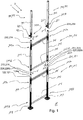
- FIG. 1 is a created from a scaffold system 1 scaffold 2 shown in exploded view.
- the scaffold system 1 or the scaffold 2 comprises a first scaffold component 101, which is designed as a first, lower scaffolding frame 102, which has a first, lower hollow profile rod 103 and a second, lower Hollow section bar 104 and the hollow profile bars 103, 104 connecting transverse struts 105, 106 includes.
- the hollow profile bars 103, 104 each have an upper tube section 103a, 104a and a lower tube section 103b, 104b.
- the lower frame component 102 further comprises built-in parts 121, 122, which are designed as tube connectors 123, 124.
- the pipe connector 123 is inserted into the upper pipe section 103a of the hollow profile 103, and in this case the pipe connector 124 is inserted into the upper pipe section 104a of the hollow profile 104, so that an upper plug-in pin 123a and an upper plug-in pin 124a respectively from the upper pipe sections 103a and 104a protrude.
- a threaded foot 107 and 108 is screwed, so that the lower frame member 101 can be placed on a substrate U.
- the scaffolding system 1 or the scaffold 2 also comprises a second scaffold component 201 which is designed as a second, upper scaffolding frame 202, which comprises a first, upper hollow profile rod 203 and a second, upper hollow profile rod 204 and transverse struts 205, 206 connecting the hollow profile rods 203, 204 includes.
- the hollow profile bars 203, 204 each have an upper tube section 203a, 204a and a lower tube section 203b, 204b.
- the upper frame component 202 further comprises mounting parts 221, 222, which are designed as reducing sleeves 223, 224.
- the Reduzierhülse 223 is inserted into the lower tube portion 203b of the hollow section 203 and in this case the Reduzierhülse 224 is inserted into the lower tube portion 204b of the hollow section 204, so that the Reduzierhülse 223 and 224 is received respectively in the lower tube sections 203b and 204b.
- the second scaffolding frame 202 For assembly, it is provided to place the second scaffolding frame 202 in the direction of the arrow z 'down on the lower scaffolding 102 so that the plug 123a is inserted into an interior 225b of a sleeve body 225 of the reducing sleeve 223 and that the plug 124a into an interior 226b a sleeve body 226 of the Reduction sleeve 224 is inserted, so that the frame members 101 and 201 are connected to each other.
- a third frame component 301 is shown, which is designed as a railing post 302, which comprises a hollow profile rod 303, a Reduzierhülse 323 and a screw lug 333.
- the reducing sleeve 323 is received in a lower tube portion 303b of the hollow profile rod 303.
- the eyelet 333 is screwed through the hollow profile bar 303 in the Reduzierhülse 323.
- a fourth frame member 401 is shown, which is designed as a railing post 402, which comprises a hollow profile bar 403, a Reduzierhülse 423 and a screw 433.
- the reducing sleeve 423 is received in a lower pipe section 403b of the hollow profile bar 403.
- the eyelet 433 is screwed through the hollow profile bar 403 in the Reduzierhülse 423.
- the upper scaffolding frame 202 comprises, as further built-in parts 231, 232, two pipe connectors 233, 234 which are inserted into the upper pipe sections 203a, 204a of the scaffolding frame 202.
- this pipe connector 233, 234 can be the railing posts 302 and 402 plug in the direction of other arrows z '.
- the framework 2 can be completed by scaffolding floors not shown and railing struts, not shown, and other scaffolding frames and railing posts.
- FIG. 2a shows a side view of the second, upper scaffolding frame 202 of the in FIG. 1 shown framework 2.
- the scaffolding frame 202 in the region of the upper tube portion 204 a of its second profile bar 204 is shown enlarged.
- a side view of the scaffolding frame 202 in the region of the upper tube portion 203 a of its first profile bar 203 is shown in section.
- This Detail is in the Figure 2c shown enlarged.
- the pipe connector 233 inserted into the upper pipe section 203a can be seen both with its upper plug-in pin 233a and with its lower plug-in pin 233b.
- the pipe connector 233 is inserted with its lower plug pin 233b in a cavity H203a of the upper pipe section 203a and protrudes with its upper plug pin 233a on the hollow profile rod 203 addition.
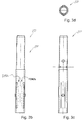
- FIGS. 3a to 3d the pipe connector 233 is shown in four views, wherein the pipe connector 233 is described by way of example for all on hollow profile bars of the scaffolding frames 102, 202 built-pipe connector.
- the pipe connector 233 is in perspective view ( FIG. 3a ), in side view in the direction of arrow y ( FIG. 3b ) and in side view in the direction of arrow x ( Figure 3c ), as well as in plan view in the direction of the arrow z '( 3d figure ).
- the pipe connector 233 comprises a double sleeve 241.
- This double sleeve 241 comprises the upper plug pin 233a and the lower plug pin 233b.
- the lower plug-in pin 233b has a first cylindrical outer circumferential surface AMF233b with a first outer diameter D233b
- the upper plug-in pin 233a has a second cylindrical outer circumferential surface AMF233a with a second outer diameter D233a.
- the lower plug-in pin 233b comprises a first latching device 242 and a second latching device 243, wherein the latching devices 242, 243 each comprise a latching lug 242a, 243a and a spring 242b, 243b, wherein each latching lug 242a, 243a in a latching position R242a, R243a, in which this is shown in the previously mentioned figures, protrudes outwardly beyond the first outer circumferential surface AMF233b.
- the locking lugs 242a, 243a by means of springs 242b, 243b so sprung on the first, lower plug pin 234b arranged that this from the rest position R242a, R243a so far against a restoring force of the respective spring 242b and 243b in the first plug pin 234b inside in a release position F242a, F243a (in FIG. 3b schematically indicated by dashed lines) can be pressed, that the locking lugs 242a, 243a are substantially flat in the first outer circumferential surface AMF233b.
- an outer diameter D233b of the lower spigot 233b is made larger than an outer diameter D233a of the upper spigot 233a, so that at a uniform inner diameter d203 (see FIG Figure 2c ) of the first hollow profile bar 203 and the same design of the other hollow profile bars of the first and second scaffolding frame or the railing post between the upper plug pin 233 a and the corresponding to the FIG. 1 on this plugged hollow profile bar 303 space for the Reduzierhülse 323 remains. From a comparative analysis of the FIGS.
- the pipe connector 233 engages with its detents 242a, 243a in opposite bores of the upper pipe section 203a of the hollow profile rod 203, when it is inserted with a corresponding orientation in the hollow profile rod 203.
- the scaffolding frame 202 is shown in a sectional view, so that the holes arranged in the upper tube section 203a of the hollow profile rod 203 are not visible.
- the hollow profile bar 204 formed comparable to the hollow profile rod 203 shown in side view, in this illustration, at the upper tube portion 204a with a bore B1-204a such a hole visible.
- a second bore B2-204a is hidden from the bore B1-204a.
- the upper tube portion 203a of the hollow profile rod 203 is formed identical with respect to these holes. Also, the hollow profile bars 103 and 104 of the lower scaffolding frame 102 (see FIG. 1 ) are identical with respect to the holes for engaging the pipe connectors 123, 124.
- a loosening of the pipe connector 233 from the hollow profile rod 203 is possible in that both locking lugs 242a, 243a are pressed in at the same time and the pipe connector 233 is pulled out of the hollow profile rod 203.
- the spring 242b of Locking device 242 is formed by a latching portion 251 of the lower plug 233b of the double sleeve 241, which longitudinally by axially in the direction of a longitudinal axis L233 of the pipe connector 233 adjacent cuts 251a, 251b of a holding portion 252 of the lower plug pin 233b is separated and transverse to the holding portion 252nd of the lower spigot 233b is connected.
- the locking lug 242a is connected to the latching portion 251.
- the latching section 251 forms a leaf spring clamped on both sides, the clamping being effected by a direct connection to the holding section 252.
- the pipe connector 233 is formed as a plastic component, wherein the holding portion 252 and the locking portion 251 of the same material, and are integrally formed.
- the second latching device 243 of the lower plug pin 233b of the double sleeve 241 is analogous to the first latching device 242 and this formed opposite.
- the other previously mentioned pipe connectors are each formed with two such locking devices. Accordingly, the upper pipe sections of all other hollow profile bars of scaffolding frames are formed with holes.
- the lower plug pin 233b and the upper plug pin 233a of the double sleeve 241 are each formed as a tubular plug-in pin with a cylindrical interior.
- the lower spigot and the upper spigot of the double sleeve are each formed as a pin-like spigot made of solid material.
- These pin-like plug-in pins then have recesses in the region of the latching devices, so that the latching sections can deflect in the direction of the longitudinal axis of the pipe connector.
- FIG. 4a shows again from the FIG. 2a known side view of the second, upper scaffolding frame 202 of the in the FIG. 1 shown framework 2.
- the scaffolding frame 202 in the region of the lower tube section 204b his second profile bar 204 shown enlarged.
- the scaffolding frame 202 is shown in section in the region of the lower tube section 203b of its first profile bar 203.
- This detail is in the Figure 4c shown enlarged.
- the inserted into the lower pipe section 203b Reduzierhülse 223 can be seen.
- the reducing sleeve 223 is received in a cavity H203b of the lower tube portion 203b.
- the Reduzierhülse 223 is shown in four views, wherein the Reduzierhülse 223 is described by way of example for all on hollow profile bars of the scaffolding frames 202, 203 Reduzierhülsen.
- the reducing sleeve 223 is in perspective view ( FIG. 5a ), in side view in the direction of arrow y ( FIG. 5b ) and in side view in the direction of arrow x ( FIG. 5c ), as well as in plan view in the direction of the arrow z '( FIG. 5d ).
- the reducing sleeve 223 comprises the sleeve body 225, which comprises a cylindrical outer circumferential surface AMF225. Furthermore, the reducing sleeve 223 comprises a first latching device 262 and a second latching device 263, wherein the latching devices 262, 263 each comprise a latching lug 262a, 263a and a spring 262b, 263b and wherein the latching lug 262a, 263a in a latching position R262a or R263a to the outside projecting beyond the outer circumferential surface AMF225 and being suspended from the sleeve body 225 in such a manner that they are displaced from the rest position R262a or R263a against a restoring force of the spring 262b, 263b into a release position F262a, F263a, with dashed lines schematically in FIG FIG. 5b indicated in the sleeve body 225 are pressed, that the locking lugs 262a, 263a
- the sleeve body 225 also includes a cylindrical inner circumferential surface IMF225, wherein the latching device 262 is designed such that the latching device 262 in the latching position R262a outside of the inner circumferential surface IMF225 defined interior 225b of the sleeve body 225 is located.
- the locking lugs 262a, 263a are formed as a cylinder. According to embodiments not shown here, it is provided to form at least one locking lug as a circular ring or as a threaded nut.
- the spring 262b of the reducing sleeve 223 is formed by a latching portion 271 of the sleeve body 225 of the reducing sleeve 223 which is longitudinally separated from a holding portion 272 of the sleeve body 225 by cuts 271a, 271b extending alongside one another in the direction of a longitudinal axis L223 of the reducing sleeve 223 is and is connected to the transverse side with the holding portion 272 of the sleeve body 225.
- the locking lug 262a is connected to the latching portion 271.
- the latching portion 271 forms a leaf spring clamped on both sides, the clamping being realized by a direct connection to the holding portion 272.
- the Reduzierhülse 223 is formed as a plastic component, wherein the holding portion 272 and the locking portion 271 of the same material, and are integrally formed.
- the second latching device 263 of the sleeve body 225 is formed analogously to the first latching device 262 and this opposite.
- the other Reduzierhülsen so far mentioned are each formed with two such locking devices.
- FIGS. 4a to 4c 5a to 5d From a comparative analysis of the FIGS. 4a to 4c 5a to 5d it can be seen that the reduction sleeve 223 with its locking lugs 262a, 263a engages in opposite bores of the lower tube section 203b of the hollow profile rod 203, when it is inserted with a corresponding orientation from below into the hollow profile rod 203.
- the scaffolding frame 202 is shown in a sectional view, so that the holes arranged in the lower tube section 203b of the hollow profile rod 203 are not visible.
- the hollow profile bar 204 formed comparable to the hollow profile bar 203 shown in side view, in this illustration is at its lower tube portion 204 b with a Bore B1-204b such a hole visible.
- a second hole B2-204b is hidden from the bore B1-204b.
- the lower tube portion 203b of the hollow profile rod 203 is formed identical with respect to these holes.
- the hollow profile bars 103 and 104 of the lower scaffolding frame 102 are identical with respect to the holes for engaging the Reduzierhülsen.
- the one in the FIG. 4b Hollow section bar 204 shown yet two more, opposite holes B3-204b and B4-204b, which correspond with inserted reducing sleeve 224 with further holes of the Reduzierhülse 224. These holes are exemplified on the identical executed and in the FIG. 5a shown reducing sleeve 223 and exemplified with B3-223 and B4-223.
- the hollow profile bars 303, 403 of the railing posts 302, 402 (see FIG. 1 ) have holes into which the Reduzierhülse 323 and 423 engages.
- the hollow profile bars 303, 402 of the glazing posts 302, 402 have bores.
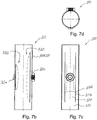
- the Figures 6a and 6b a side view and a sectional side view of the lower pipe section 303b of the railing post 302 formed third scaffolding member 301 shown in an enlarged view.
- the Reduzierhülse 323 is installed in the railing post 302. This differs from the built in the scaffolding frame reducer and is in the FIGS. 7a to 7d shown as a single component in various views, the Reduzierhülse 323 is described as an example of all installed on hollow profile bars of railing posts Reduzierhülsen.
- the Reduzierhülse 323 is in perspective view ( Figure 7a ), in side view in the direction of arrow y ( FIG. 7b ) and in side view in the direction of arrow x ( FIG. 7c ), as well as in plan view in the direction of the arrow z '( FIG. 7d ).
- the reducing sleeve 323 comprises a sleeve body 325, which comprises a cylindrical outer circumferential surface AMF325. Furthermore, the reduction sleeve 323 comprises a first latching device 362 and a second latching device 363, wherein the latching devices 362, 363 each comprise a latching lug 362a, 363a and a spring 362b, 363b and wherein the latching lug 362a, 363a in a latching position R362a or R363a to the outside protrude over the outer circumferential surface AMF325 and are so sprung on the sleeve body 325 are arranged so that this from the rest position R362a or R363a so far against a restoring force of the spring 362b, 363b in release positions F362a, F363a, with dashed lines schematically in the FIG. 7b indicated in the sleeve body 325 are pressed, that the locking lugs 362a, 363a
- the sleeve body 325 also comprises a cylindrical inner circumferential surface IMF325, wherein the latching device 362 is configured such that the latching device 362 lies in the latching position R362a outside an interior 325b of the sleeve body 325 defined by the inner circumferential surface IMF325.
- the locking lug 362a is designed as a threaded nut GWM362a.
- the detent 363a is formed as a cylinder.
- the spring 362b the Reduzierhülse 323 is formed by a latching portion 371 of the sleeve body 325 of the Reduzierhülse 323, which is longitudinally separated by axially in the direction of a longitudinal axis L323 of Reduzierhülse 323 adjacent cuts 371 a, 371 b of a holding portion 372 of the sleeve body 325 and the transverse side with the holding portion 372 of Sleeve body 325 is connected.
- the detent 362a is connected to the latching portion 371.
- the latching section 371 forms a leaf spring clamped on both sides, the clamping being realized by a direct connection to the holding section 372.
- the Reduzierhülse 323 is formed as a plastic component, wherein the holding portion 372 and the locking portion 371 of the same material, and are integrally formed.
- the second latching device 363 of the sleeve body 325 is formed analogously to the first latching device 362 and this opposite, wherein the first latching device 362 is dimensioned larger than the second latching device 363. This makes it possible that the latching portion 371 can be elastically deformed so far that the comparatively large-dimensioned threaded nut GWM362a lies flat in the outer circumferential surface AMF325, so that the reducing sleeve 323 can be inserted and ejected into the tread bar 303.
- the hollow profile rod 303 comprises at its lower tube section 303b a first bore B1-303b, which is adapted in its diameter to the latching lug 362a designed as a threaded nut GWM362a, and a second bore B2-303b, which has a diameter corresponding to the second cylinder Latch 363a is adapted (see FIGS. 6a, 6b ).
- the two bores B1-303b and B2-303b lie on a common longitudinal axis L303b, which orthogonally intersects the longitudinal axis L323 of the reducing sleeve 323.
- FIG. 1 Known screw eye 333 shown, which is screwed into the protruding from the bore B1-303b threaded nut GWM362a the Reduzierhülse 323.
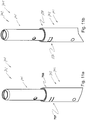
- FIGS. 8a to 8d is a third embodiment a Reduzierhülse 523 in perspective view ( FIG. 8a ), in side view in the direction of arrow y ( FIG. 8b ) and in side view in the direction of arrow x ( FIG. 8c ), as well as in plan view in the direction of the arrow z '( FIG. 8d ).
- the reducing sleeve 523 differs from that in the FIGS. 5a to 5d shown reducing sleeve 223 in that it has no holes B3-223 and B4-223 in addition to the locking lugs.
- the locking lugs 562a, 563a are not formed as cylinders, but as circular rings K562a or K563a.
- a safety bolt through the circular rings K562a, K563a and associated through these holes in a suitable for the Reduzierhülse 523, not shown hollow profile bar are inserted.
- FIGS. 9a to 9c a second embodiment of a pipe connector 601 is shown in three perspective views.
- the pipe connector 601 is formed in two parts or two layers and comprises, in addition to a double sleeve 602, in particular designed as a one-piece plastic component (see FIG. 9a ) a core sleeve 603 (see FIG. 9b ), which is designed in particular as a metal sleeve.
- the double sleeve 602 is formed as an outer sleeve.
- the core sleeve 603 is formed as an inner sleeve.
- the core sleeve 603 has a length L603 which corresponds approximately to a length L602 of the double sleeve 602.
- the complete pipe connector 601 is shown as a transparent component.
- the core sleeve 603 is inserted as an inner sleeve in the double sleeve 602, which forms an outer sleeve.
- the two sleeves 602, 603 are frictionally connected with each other.
- a variant of the invention provides that these are additionally or alternatively also glued together and / or positively connected.
- the double sleeve 602 is basically analogous to the particular in the FIG.
- two opposing receptacles 681, 682 are formed on a lower plug-in pin 233b above the latching devices 642, 643, which form recesses or depressions or openings on an outer casing surface AMF633b of the lower plug-in pin 633b.
- the core sleeve 603 comprises in the region of each latching device 642, 643 of the double sleeve 602 a notch 691, 692, wherein the notches 691, 692 are dimensioned such that each latching device 642, 643 in the direction of a longitudinal axis L601 of the pipe connector 601 undisturbed by the core sleeve 603 deformable is. Furthermore, the core sleeve 603 in the region of each bore B3-633a, B4-633a of the double sleeve 602 includes a further notch 693, 694, wherein the notches 693, 694 are each formed as a through hole.
- the core sleeve 603 also has notches 602 in the region of the recesses 681, 682 of the double sleeve 602.
- FIG. 10a and 10b a variant embodiment of a scaffolding frame 702 in the region of an upper tube section 703a of one of its hollow profile bars 703 is shown in perspective and transparent perspective view.
- the scaffolding frame 702 is basically designed in accordance with the above-described scaffolding frames 102 and 202 and has, in particular, bores B1-703a and B2-703a into which the scaffolding in the FIG. 9c shown raw connector 601 can be engaged with its locking lugs 642a, 643a, so that its receptacles 681, 682 are aligned on formed on the upper pipe section 703a forming sections 797, 798.
- the forming sections 797, 798 are formed by opposing and radially extending dividing slots 797a, 797b and 798a, 798b, which sever the upper tube section 703a. Through these radial separating slots 797a, 797b and 798a, 798b, respectively, the forming sections 797, 798 are annular-section-like (see FIG FIG. 10a ). Thus, the upper pipe section 703a can be plastically deformed in the region thereof by a pressing force and thereby pressed flat, that the forming section 797, 798 in the formed state (see FIG.
- a scaffold component such as scaffolding frame 702 is then manufactured such that first opposing and radially extending separating slots are introduced at an upper tube portion of the hollow profile rod of the scaffold component, wherein the upper tube section is severed by the separating slots, and a particular annular ring-like forming section is formed, that then the pipe connector in the end opening of the hollow profile bars are inserted such that latching devices of the pipe connector with locking lugs in holes of the hollow profile bars latched and that then a plastic impressions of the Umformabête takes place such that the deformed jacket portions protrude into cavities of the upper pipe sections and in the recess of the pipe connector.
- FIGS. 10a, 10b show analogous to the FIGS. 10a, 10b a section of a scaffolding component 701, which is completed by the inserted tube connector 601 and designed as scaffolding frames 702, in the case of undeformed forming sections 797, 798 (FIG. FIG. 11a ) and deformed forming sections 797, 798.
Landscapes
- Engineering & Computer Science (AREA)
- Architecture (AREA)
- Mechanical Engineering (AREA)
- Civil Engineering (AREA)
- Structural Engineering (AREA)
- Mutual Connection Of Rods And Tubes (AREA)
Priority Applications (1)
| Application Number | Priority Date | Filing Date | Title |
|---|---|---|---|
| PL19167863T PL3556965T3 (pl) | 2018-04-19 | 2019-04-08 | Tuleja redukcyjna, łącznik rurowy, system połączeniowy, element rusztowaniowy, system rusztowaniowy i sposób wytwarzania elementu rusztowaniowego |
Applications Claiming Priority (1)
| Application Number | Priority Date | Filing Date | Title |
|---|---|---|---|
| DE102018109386.1A DE102018109386A1 (de) | 2018-04-19 | 2018-04-19 | Reduzierhülse, Rohrverbinder, Verbindungssystem, Gerüstbauteil, Gerüstsystem sowie Verfahren zur Herstellung eines Gerüstbauteils |
Publications (3)
| Publication Number | Publication Date |
|---|---|
| EP3556965A2 true EP3556965A2 (fr) | 2019-10-23 |
| EP3556965A3 EP3556965A3 (fr) | 2020-01-15 |
| EP3556965B1 EP3556965B1 (fr) | 2021-05-19 |
Family
ID=66102524
Family Applications (1)
| Application Number | Title | Priority Date | Filing Date |
|---|---|---|---|
| EP19167863.0A Active EP3556965B1 (fr) | 2018-04-19 | 2019-04-08 | Manchon de réduction, raccord de tuyau, système de raccordement, composant d'échafaudage, système d'échafaudage ainsi que procédé de fabrication d'un composant d'échafaudage |
Country Status (3)
| Country | Link |
|---|---|
| EP (1) | EP3556965B1 (fr) |
| DE (1) | DE102018109386A1 (fr) |
| PL (1) | PL3556965T3 (fr) |
Cited By (6)
| Publication number | Priority date | Publication date | Assignee | Title |
|---|---|---|---|---|
| CN112177303A (zh) * | 2020-09-09 | 2021-01-05 | 滁州金诚金属制品有限公司 | 一种脚手架门架 |
| CN114250960A (zh) * | 2021-12-01 | 2022-03-29 | 江苏速捷模架科技有限公司 | 新型建筑施工用桁架系统 |
| CN114278066A (zh) * | 2020-09-26 | 2022-04-05 | Peri有限公司 | 脚手架节点和脚手架部段以及构造此脚手架部段的方法 |
| CN114991718A (zh) * | 2022-06-17 | 2022-09-02 | 中海石油(中国)有限公司 | 一种用于海底油气作业的路由模块作业系统 |
| CN115111242A (zh) * | 2022-06-23 | 2022-09-27 | 重庆长安汽车股份有限公司 | 一种卡扣及车用构件连接结构和汽车 |
| KR102459908B1 (ko) * | 2021-06-16 | 2022-10-31 | (주)대명이십일 | 시스템비계 시공방법 |
Citations (1)
| Publication number | Priority date | Publication date | Assignee | Title |
|---|---|---|---|---|
| DE20200728U1 (de) | 2002-01-18 | 2002-04-11 | Zarges GmbH & Co. KG, 82362 Weilheim | Gerüst-Rohrverbinder sowie Gerüst |
Family Cites Families (5)
| Publication number | Priority date | Publication date | Assignee | Title |
|---|---|---|---|---|
| JPH0322421Y2 (fr) * | 1986-03-19 | 1991-05-16 | ||
| JP2530773B2 (ja) * | 1991-06-24 | 1996-09-04 | アルインコ株式会社 | 足場用建枠 |
| JP4629245B2 (ja) * | 2001-02-13 | 2011-02-09 | エスアールジータカミヤ株式会社 | パイプジョイント |
| JP5128445B2 (ja) * | 2008-05-21 | 2013-01-23 | 信和株式会社 | 仮設足場用の柱部材 |
| JP6942933B2 (ja) * | 2016-03-29 | 2021-09-29 | 株式会社三共 | 仮設足場用継ぎ手 |
-
2018
- 2018-04-19 DE DE102018109386.1A patent/DE102018109386A1/de not_active Withdrawn
-
2019
- 2019-04-08 EP EP19167863.0A patent/EP3556965B1/fr active Active
- 2019-04-08 PL PL19167863T patent/PL3556965T3/pl unknown
Patent Citations (1)
| Publication number | Priority date | Publication date | Assignee | Title |
|---|---|---|---|---|
| DE20200728U1 (de) | 2002-01-18 | 2002-04-11 | Zarges GmbH & Co. KG, 82362 Weilheim | Gerüst-Rohrverbinder sowie Gerüst |
Cited By (8)
| Publication number | Priority date | Publication date | Assignee | Title |
|---|---|---|---|---|
| CN112177303A (zh) * | 2020-09-09 | 2021-01-05 | 滁州金诚金属制品有限公司 | 一种脚手架门架 |
| CN114278066A (zh) * | 2020-09-26 | 2022-04-05 | Peri有限公司 | 脚手架节点和脚手架部段以及构造此脚手架部段的方法 |
| CN114278066B (zh) * | 2020-09-26 | 2023-07-25 | 派利公司 | 脚手架节点和脚手架部段以及构造此脚手架部段的方法 |
| KR102459908B1 (ko) * | 2021-06-16 | 2022-10-31 | (주)대명이십일 | 시스템비계 시공방법 |
| CN114250960A (zh) * | 2021-12-01 | 2022-03-29 | 江苏速捷模架科技有限公司 | 新型建筑施工用桁架系统 |
| CN114991718A (zh) * | 2022-06-17 | 2022-09-02 | 中海石油(中国)有限公司 | 一种用于海底油气作业的路由模块作业系统 |
| CN115111242A (zh) * | 2022-06-23 | 2022-09-27 | 重庆长安汽车股份有限公司 | 一种卡扣及车用构件连接结构和汽车 |
| CN115111242B (zh) * | 2022-06-23 | 2024-05-24 | 重庆长安汽车股份有限公司 | 一种卡扣及车用构件连接结构和汽车 |
Also Published As
| Publication number | Publication date |
|---|---|
| EP3556965A3 (fr) | 2020-01-15 |
| PL3556965T4 (pl) | 2021-11-22 |
| EP3556965B1 (fr) | 2021-05-19 |
| PL3556965T3 (pl) | 2021-11-22 |
| DE102018109386A1 (de) | 2019-10-24 |
Similar Documents
| Publication | Publication Date | Title |
|---|---|---|
| EP3556965B1 (fr) | Manchon de réduction, raccord de tuyau, système de raccordement, composant d'échafaudage, système d'échafaudage ainsi que procédé de fabrication d'un composant d'échafaudage | |
| DE2811404A1 (de) | Verbindungsanordnung zur loesbaren kopplung von lichtleitern | |
| EP3954905B1 (fr) | Élément ressort | |
| DE3328242A1 (de) | Vorrichtung zum sichern der verbindung zweier gehaeuseschalen eines fuer die aufnahme elektrischer bauelemente bzw. baugruppen dienenden gehaeuses | |
| WO2008000249A1 (fr) | Cage de palier comprenant une pluralité de colliers de fixation | |
| AT405960B (de) | Schliesszylinder | |
| EP0773615B1 (fr) | Armoire de commutation pour installation électrique | |
| EP1615528A1 (fr) | Element de liaison et systeme de bati | |
| WO2021156299A1 (fr) | Trampoline | |
| DE10112035B4 (de) | Schutzzaun | |
| DE19517221B4 (de) | Steckverbinderkupplung für elektrische Leitungsverbinder | |
| EP3217085B1 (fr) | Chassis de luminaire | |
| WO2008068304A2 (fr) | Crémone | |
| DE2725921A1 (de) | Mehrteilige hohlstange | |
| DE29517396U1 (de) | Elektrischer Steckverbinder | |
| DE4241771A1 (de) | Dachreling für Kraftfahrzeuge | |
| DE102021202797B3 (de) | Verfahren zum Herauslösen eines Spannstifts und Vorrichtung zur Durchführung des Verfahrens | |
| DE19748456B4 (de) | Verbindungsvorrichtung und Schirm mit einer solchen Verbindungsvorrichtung | |
| DE102007014013B4 (de) | Flugkörperadapterring | |
| EP0852922A1 (fr) | Dispositif de raccordement | |
| DE3523690A1 (de) | Hakenkern zum zusammenbau von profilteilen | |
| EP3199053B1 (fr) | Raccord rapide pour une protection contre les intempéries | |
| DE102023114895A1 (de) | Türband für eine verdeckte Anordnung | |
| EP2030478A2 (fr) | Moyen d'assemblage pour boitier d'appareils auditifs | |
| DE2323566C3 (de) | Zylinderschloß mit achsparallelen lamellenförmigen Zuhaltungen |
Legal Events
| Date | Code | Title | Description |
|---|---|---|---|
| PUAI | Public reference made under article 153(3) epc to a published international application that has entered the european phase |
Free format text: ORIGINAL CODE: 0009012 |
|
| STAA | Information on the status of an ep patent application or granted ep patent |
Free format text: STATUS: THE APPLICATION HAS BEEN PUBLISHED |
|
| AK | Designated contracting states |
Kind code of ref document: A2 Designated state(s): AL AT BE BG CH CY CZ DE DK EE ES FI FR GB GR HR HU IE IS IT LI LT LU LV MC MK MT NL NO PL PT RO RS SE SI SK SM TR |
|
| AX | Request for extension of the european patent |
Extension state: BA ME |
|
| PUAL | Search report despatched |
Free format text: ORIGINAL CODE: 0009013 |
|
| AK | Designated contracting states |
Kind code of ref document: A3 Designated state(s): AL AT BE BG CH CY CZ DE DK EE ES FI FR GB GR HR HU IE IS IT LI LT LU LV MC MK MT NL NO PL PT RO RS SE SI SK SM TR |
|
| AX | Request for extension of the european patent |
Extension state: BA ME |
|
| RIC1 | Information provided on ipc code assigned before grant |
Ipc: E04G 1/06 20060101AFI20191206BHEP Ipc: F16B 7/04 20060101ALI20191206BHEP Ipc: E04G 7/30 20060101ALI20191206BHEP Ipc: E04G 1/14 20060101ALI20191206BHEP Ipc: E04G 7/20 20060101ALI20191206BHEP |
|
| STAA | Information on the status of an ep patent application or granted ep patent |
Free format text: STATUS: REQUEST FOR EXAMINATION WAS MADE |
|
| 17P | Request for examination filed |
Effective date: 20200713 |
|
| RBV | Designated contracting states (corrected) |
Designated state(s): AL AT BE BG CH CY CZ DE DK EE ES FI FR GB GR HR HU IE IS IT LI LT LU LV MC MK MT NL NO PL PT RO RS SE SI SK SM TR |
|
| GRAP | Despatch of communication of intention to grant a patent |
Free format text: ORIGINAL CODE: EPIDOSNIGR1 |
|
| STAA | Information on the status of an ep patent application or granted ep patent |
Free format text: STATUS: GRANT OF PATENT IS INTENDED |
|
| INTG | Intention to grant announced |
Effective date: 20210112 |
|
| GRAS | Grant fee paid |
Free format text: ORIGINAL CODE: EPIDOSNIGR3 |
|
| GRAA | (expected) grant |
Free format text: ORIGINAL CODE: 0009210 |
|
| STAA | Information on the status of an ep patent application or granted ep patent |
Free format text: STATUS: THE PATENT HAS BEEN GRANTED |
|
| AK | Designated contracting states |
Kind code of ref document: B1 Designated state(s): AL AT BE BG CH CY CZ DE DK EE ES FI FR GB GR HR HU IE IS IT LI LT LU LV MC MK MT NL NO PL PT RO RS SE SI SK SM TR |
|
| REG | Reference to a national code |
Ref country code: GB Ref legal event code: FG4D Free format text: NOT ENGLISH |
|
| REG | Reference to a national code |
Ref country code: CH Ref legal event code: EP |
|
| REG | Reference to a national code |
Ref country code: DE Ref legal event code: R096 Ref document number: 502019001439 Country of ref document: DE |
|
| REG | Reference to a national code |
Ref country code: AT Ref legal event code: REF Ref document number: 1394092 Country of ref document: AT Kind code of ref document: T Effective date: 20210615 |
|
| REG | Reference to a national code |
Ref country code: IE Ref legal event code: FG4D Free format text: LANGUAGE OF EP DOCUMENT: GERMAN |
|
| REG | Reference to a national code |
Ref country code: LT Ref legal event code: MG9D |
|
| REG | Reference to a national code |
Ref country code: NL Ref legal event code: MP Effective date: 20210519 |
|
| PG25 | Lapsed in a contracting state [announced via postgrant information from national office to epo] |
Ref country code: BG Free format text: LAPSE BECAUSE OF FAILURE TO SUBMIT A TRANSLATION OF THE DESCRIPTION OR TO PAY THE FEE WITHIN THE PRESCRIBED TIME-LIMIT Effective date: 20210819 Ref country code: LT Free format text: LAPSE BECAUSE OF FAILURE TO SUBMIT A TRANSLATION OF THE DESCRIPTION OR TO PAY THE FEE WITHIN THE PRESCRIBED TIME-LIMIT Effective date: 20210519 Ref country code: HR Free format text: LAPSE BECAUSE OF FAILURE TO SUBMIT A TRANSLATION OF THE DESCRIPTION OR TO PAY THE FEE WITHIN THE PRESCRIBED TIME-LIMIT Effective date: 20210519 Ref country code: FI Free format text: LAPSE BECAUSE OF FAILURE TO SUBMIT A TRANSLATION OF THE DESCRIPTION OR TO PAY THE FEE WITHIN THE PRESCRIBED TIME-LIMIT Effective date: 20210519 |
|
| PG25 | Lapsed in a contracting state [announced via postgrant information from national office to epo] |
Ref country code: IS Free format text: LAPSE BECAUSE OF FAILURE TO SUBMIT A TRANSLATION OF THE DESCRIPTION OR TO PAY THE FEE WITHIN THE PRESCRIBED TIME-LIMIT Effective date: 20210919 Ref country code: GR Free format text: LAPSE BECAUSE OF FAILURE TO SUBMIT A TRANSLATION OF THE DESCRIPTION OR TO PAY THE FEE WITHIN THE PRESCRIBED TIME-LIMIT Effective date: 20210820 Ref country code: LV Free format text: LAPSE BECAUSE OF FAILURE TO SUBMIT A TRANSLATION OF THE DESCRIPTION OR TO PAY THE FEE WITHIN THE PRESCRIBED TIME-LIMIT Effective date: 20210519 Ref country code: NO Free format text: LAPSE BECAUSE OF FAILURE TO SUBMIT A TRANSLATION OF THE DESCRIPTION OR TO PAY THE FEE WITHIN THE PRESCRIBED TIME-LIMIT Effective date: 20210819 Ref country code: PT Free format text: LAPSE BECAUSE OF FAILURE TO SUBMIT A TRANSLATION OF THE DESCRIPTION OR TO PAY THE FEE WITHIN THE PRESCRIBED TIME-LIMIT Effective date: 20210920 Ref country code: RS Free format text: LAPSE BECAUSE OF FAILURE TO SUBMIT A TRANSLATION OF THE DESCRIPTION OR TO PAY THE FEE WITHIN THE PRESCRIBED TIME-LIMIT Effective date: 20210519 Ref country code: SE Free format text: LAPSE BECAUSE OF FAILURE TO SUBMIT A TRANSLATION OF THE DESCRIPTION OR TO PAY THE FEE WITHIN THE PRESCRIBED TIME-LIMIT Effective date: 20210519 |
|
| PG25 | Lapsed in a contracting state [announced via postgrant information from national office to epo] |
Ref country code: NL Free format text: LAPSE BECAUSE OF FAILURE TO SUBMIT A TRANSLATION OF THE DESCRIPTION OR TO PAY THE FEE WITHIN THE PRESCRIBED TIME-LIMIT Effective date: 20210519 |
|
| PG25 | Lapsed in a contracting state [announced via postgrant information from national office to epo] |
Ref country code: CZ Free format text: LAPSE BECAUSE OF FAILURE TO SUBMIT A TRANSLATION OF THE DESCRIPTION OR TO PAY THE FEE WITHIN THE PRESCRIBED TIME-LIMIT Effective date: 20210519 Ref country code: DK Free format text: LAPSE BECAUSE OF FAILURE TO SUBMIT A TRANSLATION OF THE DESCRIPTION OR TO PAY THE FEE WITHIN THE PRESCRIBED TIME-LIMIT Effective date: 20210519 Ref country code: SM Free format text: LAPSE BECAUSE OF FAILURE TO SUBMIT A TRANSLATION OF THE DESCRIPTION OR TO PAY THE FEE WITHIN THE PRESCRIBED TIME-LIMIT Effective date: 20210519 Ref country code: RO Free format text: LAPSE BECAUSE OF FAILURE TO SUBMIT A TRANSLATION OF THE DESCRIPTION OR TO PAY THE FEE WITHIN THE PRESCRIBED TIME-LIMIT Effective date: 20210519 Ref country code: ES Free format text: LAPSE BECAUSE OF FAILURE TO SUBMIT A TRANSLATION OF THE DESCRIPTION OR TO PAY THE FEE WITHIN THE PRESCRIBED TIME-LIMIT Effective date: 20210519 Ref country code: EE Free format text: LAPSE BECAUSE OF FAILURE TO SUBMIT A TRANSLATION OF THE DESCRIPTION OR TO PAY THE FEE WITHIN THE PRESCRIBED TIME-LIMIT Effective date: 20210519 Ref country code: SK Free format text: LAPSE BECAUSE OF FAILURE TO SUBMIT A TRANSLATION OF THE DESCRIPTION OR TO PAY THE FEE WITHIN THE PRESCRIBED TIME-LIMIT Effective date: 20210519 |
|
| REG | Reference to a national code |
Ref country code: DE Ref legal event code: R097 Ref document number: 502019001439 Country of ref document: DE |
|
| PLBE | No opposition filed within time limit |
Free format text: ORIGINAL CODE: 0009261 |
|
| STAA | Information on the status of an ep patent application or granted ep patent |
Free format text: STATUS: NO OPPOSITION FILED WITHIN TIME LIMIT |
|
| 26N | No opposition filed |
Effective date: 20220222 |
|
| PG25 | Lapsed in a contracting state [announced via postgrant information from national office to epo] |
Ref country code: IS Free format text: LAPSE BECAUSE OF FAILURE TO SUBMIT A TRANSLATION OF THE DESCRIPTION OR TO PAY THE FEE WITHIN THE PRESCRIBED TIME-LIMIT Effective date: 20210919 Ref country code: AL Free format text: LAPSE BECAUSE OF FAILURE TO SUBMIT A TRANSLATION OF THE DESCRIPTION OR TO PAY THE FEE WITHIN THE PRESCRIBED TIME-LIMIT Effective date: 20210519 |
|
| PG25 | Lapsed in a contracting state [announced via postgrant information from national office to epo] |
Ref country code: IT Free format text: LAPSE BECAUSE OF FAILURE TO SUBMIT A TRANSLATION OF THE DESCRIPTION OR TO PAY THE FEE WITHIN THE PRESCRIBED TIME-LIMIT Effective date: 20210519 |
|
| REG | Reference to a national code |
Ref country code: CH Ref legal event code: PL |
|
| REG | Reference to a national code |
Ref country code: BE Ref legal event code: MM Effective date: 20220430 |
|
| PG25 | Lapsed in a contracting state [announced via postgrant information from national office to epo] |
Ref country code: MC Free format text: LAPSE BECAUSE OF FAILURE TO SUBMIT A TRANSLATION OF THE DESCRIPTION OR TO PAY THE FEE WITHIN THE PRESCRIBED TIME-LIMIT Effective date: 20210519 Ref country code: LU Free format text: LAPSE BECAUSE OF NON-PAYMENT OF DUE FEES Effective date: 20220408 Ref country code: LI Free format text: LAPSE BECAUSE OF NON-PAYMENT OF DUE FEES Effective date: 20220430 Ref country code: CH Free format text: LAPSE BECAUSE OF NON-PAYMENT OF DUE FEES Effective date: 20220430 |
|
| PG25 | Lapsed in a contracting state [announced via postgrant information from national office to epo] |
Ref country code: BE Free format text: LAPSE BECAUSE OF NON-PAYMENT OF DUE FEES Effective date: 20220430 |
|
| PG25 | Lapsed in a contracting state [announced via postgrant information from national office to epo] |
Ref country code: IE Free format text: LAPSE BECAUSE OF NON-PAYMENT OF DUE FEES Effective date: 20220408 |
|
| PGFP | Annual fee paid to national office [announced via postgrant information from national office to epo] |
Ref country code: PL Payment date: 20230327 Year of fee payment: 5 |
|
| PGFP | Annual fee paid to national office [announced via postgrant information from national office to epo] |
Ref country code: FR Payment date: 20230417 Year of fee payment: 5 Ref country code: DE Payment date: 20230418 Year of fee payment: 5 |
|
| PGFP | Annual fee paid to national office [announced via postgrant information from national office to epo] |
Ref country code: GB Payment date: 20230420 Year of fee payment: 5 |
|
| PG25 | Lapsed in a contracting state [announced via postgrant information from national office to epo] |
Ref country code: HU Free format text: LAPSE BECAUSE OF FAILURE TO SUBMIT A TRANSLATION OF THE DESCRIPTION OR TO PAY THE FEE WITHIN THE PRESCRIBED TIME-LIMIT; INVALID AB INITIO Effective date: 20190408 |
|
| PG25 | Lapsed in a contracting state [announced via postgrant information from national office to epo] |
Ref country code: MK Free format text: LAPSE BECAUSE OF FAILURE TO SUBMIT A TRANSLATION OF THE DESCRIPTION OR TO PAY THE FEE WITHIN THE PRESCRIBED TIME-LIMIT Effective date: 20210519 Ref country code: CY Free format text: LAPSE BECAUSE OF FAILURE TO SUBMIT A TRANSLATION OF THE DESCRIPTION OR TO PAY THE FEE WITHIN THE PRESCRIBED TIME-LIMIT Effective date: 20210519 |
|
| PG25 | Lapsed in a contracting state [announced via postgrant information from national office to epo] |
Ref country code: MT Free format text: LAPSE BECAUSE OF FAILURE TO SUBMIT A TRANSLATION OF THE DESCRIPTION OR TO PAY THE FEE WITHIN THE PRESCRIBED TIME-LIMIT Effective date: 20210519 |
|
| REG | Reference to a national code |
Ref country code: DE Ref legal event code: R119 Ref document number: 502019001439 Country of ref document: DE |
|
| GBPC | Gb: european patent ceased through non-payment of renewal fee |
Effective date: 20240408 |
|
| PG25 | Lapsed in a contracting state [announced via postgrant information from national office to epo] |
Ref country code: DE Free format text: LAPSE BECAUSE OF NON-PAYMENT OF DUE FEES Effective date: 20241105 |
|
| PG25 | Lapsed in a contracting state [announced via postgrant information from national office to epo] |
Ref country code: GB Free format text: LAPSE BECAUSE OF NON-PAYMENT OF DUE FEES Effective date: 20240408 |
|
| PG25 | Lapsed in a contracting state [announced via postgrant information from national office to epo] |
Ref country code: FR Free format text: LAPSE BECAUSE OF NON-PAYMENT OF DUE FEES Effective date: 20240430 |
|
| PG25 | Lapsed in a contracting state [announced via postgrant information from national office to epo] |
Ref country code: GB Free format text: LAPSE BECAUSE OF NON-PAYMENT OF DUE FEES Effective date: 20240408 Ref country code: FR Free format text: LAPSE BECAUSE OF NON-PAYMENT OF DUE FEES Effective date: 20240430 Ref country code: DE Free format text: LAPSE BECAUSE OF NON-PAYMENT OF DUE FEES Effective date: 20241105 |
|
| REG | Reference to a national code |
Ref country code: AT Ref legal event code: MM01 Ref document number: 1394092 Country of ref document: AT Kind code of ref document: T Effective date: 20240408 |
|
| PG25 | Lapsed in a contracting state [announced via postgrant information from national office to epo] |
Ref country code: AT Free format text: LAPSE BECAUSE OF NON-PAYMENT OF DUE FEES Effective date: 20240408 |
|
| PG25 | Lapsed in a contracting state [announced via postgrant information from national office to epo] |
Ref country code: PL Free format text: LAPSE BECAUSE OF NON-PAYMENT OF DUE FEES Effective date: 20240408 |
|
| PG25 | Lapsed in a contracting state [announced via postgrant information from national office to epo] |
Ref country code: TR Free format text: LAPSE BECAUSE OF FAILURE TO SUBMIT A TRANSLATION OF THE DESCRIPTION OR TO PAY THE FEE WITHIN THE PRESCRIBED TIME-LIMIT Effective date: 20210519 |