EP3556436A1 - Absorbeur à charbon actif - Google Patents
Absorbeur à charbon actif Download PDFInfo
- Publication number
- EP3556436A1 EP3556436A1 EP19174224.6A EP19174224A EP3556436A1 EP 3556436 A1 EP3556436 A1 EP 3556436A1 EP 19174224 A EP19174224 A EP 19174224A EP 3556436 A1 EP3556436 A1 EP 3556436A1
- Authority
- EP
- European Patent Office
- Prior art keywords
- activated carbon
- carbon absorber
- housing
- absorber
- adapter
- Prior art date
- Legal status (The legal status is an assumption and is not a legal conclusion. Google has not performed a legal analysis and makes no representation as to the accuracy of the status listed.)
- Pending
Links
Images


Classifications
-
- A—HUMAN NECESSITIES
- A42—HEADWEAR
- A42B—HATS; HEAD COVERINGS
- A42B3/00—Helmets; Helmet covers ; Other protective head coverings
- A42B3/04—Parts, details or accessories of helmets
- A42B3/28—Ventilating arrangements
- A42B3/285—Ventilating arrangements with additional heating or cooling means
-
- A—HUMAN NECESSITIES
- A62—LIFE-SAVING; FIRE-FIGHTING
- A62B—DEVICES, APPARATUS OR METHODS FOR LIFE-SAVING
- A62B19/00—Cartridges with absorbing substances for respiratory apparatus
-
- A—HUMAN NECESSITIES
- A62—LIFE-SAVING; FIRE-FIGHTING
- A62B—DEVICES, APPARATUS OR METHODS FOR LIFE-SAVING
- A62B23/00—Filters for breathing-protection purposes
- A62B23/02—Filters for breathing-protection purposes for respirators
-
- A—HUMAN NECESSITIES
- A62—LIFE-SAVING; FIRE-FIGHTING
- A62B—DEVICES, APPARATUS OR METHODS FOR LIFE-SAVING
- A62B7/00—Respiratory apparatus
- A62B7/02—Respiratory apparatus with compressed oxygen or air
-
- A—HUMAN NECESSITIES
- A62—LIFE-SAVING; FIRE-FIGHTING
- A62B—DEVICES, APPARATUS OR METHODS FOR LIFE-SAVING
- A62B7/00—Respiratory apparatus
- A62B7/10—Respiratory apparatus with filter elements
-
- A—HUMAN NECESSITIES
- A62—LIFE-SAVING; FIRE-FIGHTING
- A62B—DEVICES, APPARATUS OR METHODS FOR LIFE-SAVING
- A62B9/00—Component parts for respiratory or breathing apparatus
- A62B9/003—Means for influencing the temperature or humidity of the breathing gas
-
- A—HUMAN NECESSITIES
- A62—LIFE-SAVING; FIRE-FIGHTING
- A62B—DEVICES, APPARATUS OR METHODS FOR LIFE-SAVING
- A62B9/00—Component parts for respiratory or breathing apparatus
- A62B9/04—Couplings; Supporting frames
-
- B—PERFORMING OPERATIONS; TRANSPORTING
- B01—PHYSICAL OR CHEMICAL PROCESSES OR APPARATUS IN GENERAL
- B01J—CHEMICAL OR PHYSICAL PROCESSES, e.g. CATALYSIS OR COLLOID CHEMISTRY; THEIR RELEVANT APPARATUS
- B01J20/00—Solid sorbent compositions or filter aid compositions; Sorbents for chromatography; Processes for preparing, regenerating or reactivating thereof
- B01J20/30—Processes for preparing, regenerating, or reactivating
- B01J20/34—Regenerating or reactivating
- B01J20/3416—Regenerating or reactivating of sorbents or filter aids comprising free carbon, e.g. activated carbon
-
- B—PERFORMING OPERATIONS; TRANSPORTING
- B05—SPRAYING OR ATOMISING IN GENERAL; APPLYING FLUENT MATERIALS TO SURFACES, IN GENERAL
- B05B—SPRAYING APPARATUS; ATOMISING APPARATUS; NOZZLES
- B05B7/00—Spraying apparatus for discharge of liquids or other fluent materials from two or more sources, e.g. of liquid and air, of powder and gas
- B05B7/24—Spraying apparatus for discharge of liquids or other fluent materials from two or more sources, e.g. of liquid and air, of powder and gas with means, e.g. a container, for supplying liquid or other fluent material to a discharge device
- B05B7/2402—Apparatus to be carried on or by a person, e.g. by hand; Apparatus comprising containers fixed to the discharge device
- B05B7/2405—Apparatus to be carried on or by a person, e.g. by hand; Apparatus comprising containers fixed to the discharge device using an atomising fluid as carrying fluid for feeding, e.g. by suction or pressure, a carried liquid from the container to the nozzle
- B05B7/2416—Apparatus to be carried on or by a person, e.g. by hand; Apparatus comprising containers fixed to the discharge device using an atomising fluid as carrying fluid for feeding, e.g. by suction or pressure, a carried liquid from the container to the nozzle characterised by the means for producing or supplying the atomising fluid, e.g. air hoses, air pumps, gas containers, compressors, fans, ventilators, their drives
-
- B—PERFORMING OPERATIONS; TRANSPORTING
- B05—SPRAYING OR ATOMISING IN GENERAL; APPLYING FLUENT MATERIALS TO SURFACES, IN GENERAL
- B05B—SPRAYING APPARATUS; ATOMISING APPARATUS; NOZZLES
- B05B7/00—Spraying apparatus for discharge of liquids or other fluent materials from two or more sources, e.g. of liquid and air, of powder and gas
- B05B7/24—Spraying apparatus for discharge of liquids or other fluent materials from two or more sources, e.g. of liquid and air, of powder and gas with means, e.g. a container, for supplying liquid or other fluent material to a discharge device
- B05B7/2489—Spraying apparatus for discharge of liquids or other fluent materials from two or more sources, e.g. of liquid and air, of powder and gas with means, e.g. a container, for supplying liquid or other fluent material to a discharge device an atomising fluid, e.g. a gas, being supplied to the discharge device
- B05B7/2491—Spraying apparatus for discharge of liquids or other fluent materials from two or more sources, e.g. of liquid and air, of powder and gas with means, e.g. a container, for supplying liquid or other fluent material to a discharge device an atomising fluid, e.g. a gas, being supplied to the discharge device characterised by the means for producing or supplying the atomising fluid, e.g. air hoses, air pumps, gas containers, compressors, fans, ventilators, their drives
Definitions
- the present invention relates to an activated carbon absorber, in particular an activated carbon absorber for use by a user of a ventilated respirator or respirator.
- Respiratory protective hoods which can preferably be fastened over the entire head and in particular in front of the entire face of the worker, are excellently suited for this purpose and offer maximum health protection.
- breathing hoods are usually compressed air-fed independently of the ambient air.
- compressed air is initially as a rule fed to an air treatment system, which first comprises a single-stage or multi-stage filter system.
- the filtered air is then fed via a compressed air hose to a waistband or hip belt, which is usually equipped with at least one further air treatment module.
- An air treatment module may be an activated carbon absorber, another air treatment module may be an air heater or a humidifier. With the help of the activated carbon absorber module unwanted vapors and gases can be removed, which may still be contained in the compressed air. And an air heater module and / or a humidifier module can provide further health and well-being benefits.
- a further advantageous embodiment is to attach an air control and distributor module on the waistband or hip belt.
- the entire structure is commonly referred to as a belt unit.
- Such an advantageous belt unit is known for use in a breathing hood with the product name "Vision 2000" of SATA GmbH & Co. KG.
- the object of the invention is to show a way how the aforementioned problems can be solved.
- the object of the invention is achieved by an activated carbon unit having the features of claim 1.
- the housing according to the invention of the activated carbon absorber module is easy to assemble, assemble, handle and disassemble.
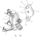
- the activated carbon absorber 100 of the present invention is intended for use by a user of a ventilated respirator or respirator.
- the activated carbon adsorber 100 on a filter cartridge 101, which is arranged in a special housing 2.3.
- the housing 2, 3 is composed of two hollow hemispheres or half shells 2 and 3.
- the half shells 2, 3 are connected together along a seam line 300.
- the compound may be a detachable or an insoluble compound. Clip-on, glued or welded joints are possible.
- the hemispheres 2, 3 are provided on two opposite sides, each with a relatively large opening 103, one of which allows the insertion and removal of an activated carbon-containing component 101 and the other the insertion and removal of a device for temperature compensation.
- Each opening 103 is closed by a screw cap 104.
- a single opening 103 from.
- the activated carbon is housed in a filter cartridge 101, which is formed as a tube, namely as a straight, cylindrical tube.
- the carbon particles are housed in the walls of the tube 101, which are closed at their ends.
- the outer diameter of the tube 101 is slightly smaller than the diameter of the openings 103 and the length of the tube 101 is slightly smaller than the diameter of the two housing half balls 2, 3 and the housing ball. Therefore, the tube 101 is easily inserted into the openings 103.
- the tube 101 is provided at one of its two ends with a closure plate which is dimensionally matched to the dimensions of one of the two openings 103 in the housing 2, 3 of the activated carbon absorber 100 that the opening 103 can be closed by the closure plate.
- the closure plate may include protrusions and / or depressions as handles and / or attachment means such as a thread which may cooperate with threads on the opening 103 and / or on the screw cap 104.
- a device for temperature compensation in the cavity 1011 of the tube 101, a device for temperature compensation, respectively.
- an air heater / air cooler module 102 may be inserted if desired.
- the breathing air reaches the craftsman with a comfortable, comfortable temperature, which he will choose to warm in the winter time so as not to catch a cold. In summertime, he can choose the air temperature cooler, so as not to sweat too much.
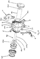
- the temperature compensation device 102 comprises a cylindrical hollow body 106 made of plastic with a hot air duct 1042 and with a cold air duct 1040, wherein the channels 1042 and 1040 in the longitudinal direction of the hollow body 106 adjoin one another and are in fluid communication.
- the inner diameter of the hot air passage 1042 is made smaller than that of the cold air passage 1040; the length of the hot air duct 1042 is substantially greater than that of the cold air duct 1040. In the present embodiment, the hot air duct 1042 is about four times as long as the cold air duct 1040.
- an air guide element or air bypass element over a large part of the total length of the hot air duct 1042.
- the air bypass element can also be arranged in any other suitable form.
- the air guide element also has a so-called star.
- a circular disk-shaped air swirl element 141 is arranged as an air guide element, namely integrally formed.
- the inner diameter of the air swirl element 141 is about twice that of the cold air passage 1040.
- the air swirl element 141 is internally provided with a plurality of swirl elements extending in the radial direction about the central axis of the body 106, each swirl element being hollow.
- the air swirl element 141 terminates in an annular plate 144, which in the preferred embodiment shown is not fixed to the cold air duct 1040 but to the hot air duct 1042, in particular integrally formed on this duct 1042.
- the annular plate 144 has a slightly smaller diameter than the cylindrical wall of the Heildrallelements 141.
- the hot air duct 1042 and the cold air duct 1040 are connected to each other in the region of the annular plate 144; simply nested in the present embodiment and hold with interference fit.
- the inner diameter of the Heildrallelements 141 is approximately twice that of the hot air duct 1042.
- the operating principle of the temperature compensation device according to the invention corresponds to a vortex or vortex principle and therefore need not here be explained in more detail.
- the shown and described length / diameter ratios of hot air duct 1042 and cold air duct 1040 in the overall body 102 ensure in any case a meaningful for human use air temperature compensation.
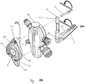
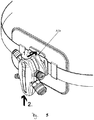
- a preferred embodiment of the invention is provided to attach the activated carbon absorber 100 via a special attachment unit 4 and then via a special adapter 15 on the hip belt 200.
- a special attachment unit 4 brings the activated carbon absorber 100 in the vicinity of one of the user's hands and thus greatly increases the ease of use.
- housing 2, 3 differs in outline and in certain details, although from the outline and certain details of Fig. 8 shown housing 2, 3 from. However, essential details are the same, which is why the invention will be described below with reference to this embodiment.
- the housing 2, 3 and this of the activated carbon absorber accordingly comprises a first half-shell 2 and a second half-shell 3.
- Both activated carbon absorber ie the one after the Fig. 1A . 1B . 2A . 2 B . 4 and 5 as well as the one after Fig. 8 , Can be mounted on their housing 2, 3 by means of the same attachment unit 4 on a hip belt 200 and removed as needed again.
- the activated carbon absorber 100 is provided with an air inlet connector 7 through which compressed air from an external compressed air supply can be introduced into the activated carbon absorber 100.
- a connector 6 for a hose or the like leading to a respirator or hood is disposed on the same side of the housing 2, 3 as the air inlet connector 7, but above this air inlet connector 7.
- a port 9 is arranged on the other side of the activated carbon absorber 100, which leads to the output of compressed air via a hose or the like to a compressed air-operated hand tool such as a paint spray gun.
- a regulator 8 which serves to adjust the pressure of the air leading to the respiratory mask or hood.
- the regulator 8 is configured such that the activated carbon absorber 100 always supplies air at a predetermined pressure to the respiratory mask or hood even when the regulator 8 is set to "minimum".
- the connector 6 for connection with the respirator or hood and / or the connection 9 for the spray gun can be closed by a blind cover or the like when not using the activated carbon absorber 100, if desired.
- the activated carbon absorber 100 may be connected to a pressure gauge (not shown in the figures).
- the second half-shell 3 of the activated carbon absorber 100 is provided with a hinged holder 5, on which the spray gun or the breathing air hose can be maintained when the spray gun or the respirator or hood is not used.
- a first arm of the here two-armed holder 5 is attached to the activated carbon absorber 100 by means of a screw 11.
- the other, second arm of the holder 5 is pivotally connected to the first arm and is otherwise free. It can be rotated relative to the activated carbon absorber 100.
- the second arm of the holder 5 at an angle between 20 ° rotated to 90 °, preferably at an angle of 70 °.
- a first locking element 52 preferably a magnet
- the locking element 52 cooperates with a second locking element (preferably with a magnet) provided on the activated carbon absorber 100.
- the second locking element is attached to the holder 5 in the region of a plate seat 51, which is provided at the upper non-free end of the first arm of the holder 5.
- the holder 5 can be securely held in the folded position when not in use on the activated carbon absorber 100.
- a recessed groove 31 inserted in the second half-shell 3 of the housing.
- the groove 31 is dimensionally matched to the holder 5, that the second arm is flush in the retracted position in the groove 31, except for a handle 500 at the upper end.
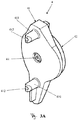
- the Fig. 3A and 3B respectively illustrate the attachment unit 4 of the activated carbon absorber 100 in front view and rear view.
- the fastening unit 4 comprises connecting elements 41, 42 which are suitable for connecting the first half shell 2 of the housing of the activated carbon absorber 100 to an adapter 15 belonging to a hip belt 200 (see FIG. Fig. 4 ).
- substantially oval shaped first connecting element 41 of the fixing unit 4 has two hollow projections 411 which are arranged above and below the connecting element 41 and projecting in the direction of the first half-shell 2 of the housing of the activated carbon absorber.
- a mounting hole 412 is inserted in each projection 411.
- the first half-shell 2 has corresponding fastening holes into which the projections 411 can be inserted.
- screws 11 are used, which engage through the top and bottom of the first arm of the holder 5 plate seats 51 through recessed mounting holes 53, and then through mounting holes in the first half-shell 2 and in the second half-shell 3 of the housing of the activated carbon absorber 100th
- the fixing unit 4 is fastened by means of bolts 12.
- bolt seats 413 are provided for screws or the like.
- two sliding slots 421 are provided on the adapter portion 42 of the fastener 4.
- the adapter region 42 is circular in outline.
- a stopper contact 422 protrudes from the peripheral surface of the adapter portion 42 from the top of the adapter portion 42.
- Two parallel projections 421b near the center of the adapter 42 protrude from the circular area, respectively represent the top of an inner wall 421a for one of the two sliding slots 421.
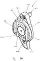
- the hip belt 200 indicated in FIGS. 10 and 11 comprises a waistband 13 which is provided with a pad 14 on its inside. On its outer side, the waistband 13 is equipped with an adapter 15 for the attachment unit 4 of the activated carbon absorber 100.
- the adapter 15 has a support plate 151 supported by the support plate 151 a mounting plate 152 and a release mechanism 153.
- Two guide rails 1521 are provided on the adapter 15, which are matched in position and shape to the two sliding slots 421 on the adapter region 42 of the fastening element 4.
- a stop member 1522 connects the two guide rails 1521 at their lower ends; the stopper 1522 and the two guide rails 1521 thus substantially form a "U" shape.
- Each guide rail 1521 includes a rib 1521a projecting from the mounting plate 152.
- the two ribs 1521a are arranged on the attachment plate 152 along the longitudinal direction of the waistband 13 and extend parallel to each other along the width direction of the waistband 13.
- each rib 1521a is provided with a protrusion 1521b protruding outward in the longitudinal direction of the waist band.
- Each projection 1521 b defines on the mounting plate 152 a guide or clip for the slide slots 421 on the adapter portion 42 of the fastener 4.
- the release mechanism 153 has a one-armed lever 153a and a handle 153b connected to the lever 153a. As shown in Fig. 10, the lever 153a is located in a recess of the upper part of the mounting plate 152.
- the lever 153a is made of a relatively flexible material, so it can be deformed when pressure is applied to the handle 153b.
- the lever 153 a is integrally formed with the mounting plate 152 and cut out of this plate 152.
- the handle 153b is integrally formed on the upper end of the lever 153a.
- the surface of the handle 153b in the present embodiment is larger than the surface of the lever, whereby a stop surface 153c between the handle 153b and the lever 153a is formed.
- Fig. 4 is shown in more detail how the activated carbon absorber 100 via the adapter portion 42 of Fastening unit 4 am attached to the hip belt 200 via the adapter 15 and can be solved again.
- the guide rails 1521 of the mounting plate 152 of the adapter 15 can be inserted after appropriate alignment by a downward pressure in the sliding slots 421 of the adapter portion 42 of the mounting unit 4. Then, since the protrusions 421b of the slide slots 421 and the protrusions 1521b of the guide rails 1521 are engaged, the activated carbon absorber 100 is securely fastened to the hip belt 200.
- the stop element 1522 on the adapter 15 restricts the sliding movements downwards, so that an undesired lowering of the activated carbon absorber 100 is prevented.
- the upper end of the stopper contact 422 on the attachment unit 4 prevents the abutment surface 153c of the release mechanism 153 of the adapter 15 from coming into undesirable contact with the activated carbon absorber 100.
- slide slots 421 on the adapter portion 42 of the attachment unit 4 and guide rails 152 on the adapter 15 of the waist belt 200 slide slots may be provided on the adapter guide rails on the attachment unit.
- Other types of sliding or sliding connections or any other releasable connection such as clip or locking connections are possible.
- the adapter 42 and the connecting member 41 of the fixing unit 4 are connected by a thin hex nut 43 and a screw 44. Since the adapter 42 is connected to the connector 41, the activated carbon absorber 100 (or another module attached to the mounting unit 4) with respect to the hip belt 200 can be rotated with respect to each other (see FIG. FIGS. 6A to 6E the previous embodiment). This contributes to a further increase in comfort for the operator.
- the activated charcoal absorber 100 is equipped with a color code system disc 10 (CCS disc).
- CCS disc color code system disc
- Various activated carbon absorbers 100 may be personalized with a color code system disk 10 of different color. Or it can be assigned to various respiratory masks or hoods in a simple manner different activated carbon absorber. Other types of attachment and color code system shapes are of course possible.
- license plates other than color code system discs is of course possible. In any case, the safety of respiratory protective devices is further improved by means of the license plates.
- all elements or sub-elements of the activated carbon absorber 100 are made of plastic.
- the two half-shells 2, 3 of the housing may have different colors. If the colors of the half shells are matched to the colors of the hip belt or of the adapter 15, assembly errors can be almost ruled out.
- a connection with the activated carbon absorber can be made on the hip belt at several points. Preferably, two locations should be chosen later on the left side and the right side of the waist of the user when the hip belt is worn by the user. Then, the activated carbon absorber can be changed by users from one side to the other, which is why the belt unit can be easily used by left and right handed people.
Applications Claiming Priority (5)
| Application Number | Priority Date | Filing Date | Title |
|---|---|---|---|
| CN201420486170.0U CN204073147U (zh) | 2014-08-26 | 2014-08-26 | 碳吸附器和腰带单元 |
| CN201420486333.5U CN204073159U (zh) | 2014-08-26 | 2014-08-26 | 温度平衡设备 |
| CN201420486205.0U CN204073150U (zh) | 2014-08-26 | 2014-08-26 | 腰带单元 |
| EP15787129.4A EP3185968B1 (fr) | 2014-08-26 | 2015-08-25 | Absorbeur à charbon actif |
| PCT/EP2015/001729 WO2016030012A2 (fr) | 2014-08-26 | 2015-08-25 | Absorbeur à charbon actif |
Related Parent Applications (1)
| Application Number | Title | Priority Date | Filing Date |
|---|---|---|---|
| EP15787129.4A Division EP3185968B1 (fr) | 2014-08-26 | 2015-08-25 | Absorbeur à charbon actif |
Publications (1)
| Publication Number | Publication Date |
|---|---|
| EP3556436A1 true EP3556436A1 (fr) | 2019-10-23 |
Family
ID=55400761
Family Applications (2)
| Application Number | Title | Priority Date | Filing Date |
|---|---|---|---|
| EP19174224.6A Pending EP3556436A1 (fr) | 2014-08-26 | 2015-08-25 | Absorbeur à charbon actif |
| EP15787129.4A Active EP3185968B1 (fr) | 2014-08-26 | 2015-08-25 | Absorbeur à charbon actif |
Family Applications After (1)
| Application Number | Title | Priority Date | Filing Date |
|---|---|---|---|
| EP15787129.4A Active EP3185968B1 (fr) | 2014-08-26 | 2015-08-25 | Absorbeur à charbon actif |
Country Status (6)
| Country | Link |
|---|---|
| US (1) | US10857400B2 (fr) |
| EP (2) | EP3556436A1 (fr) |
| JP (1) | JP2017532991A (fr) |
| CN (1) | CN106612613A (fr) |
| CA (1) | CA2958931C (fr) |
| WO (1) | WO2016030012A2 (fr) |
Families Citing this family (1)
| Publication number | Priority date | Publication date | Assignee | Title |
|---|---|---|---|---|
| DE102020109042A1 (de) * | 2019-11-21 | 2021-05-27 | Thomas Mayer | Lackiergas-Zuleitungssystem, Anlage zum Lackieren und Verfahren zum Betrieb einer Anlage zum Lackieren |
Citations (9)
| Publication number | Priority date | Publication date | Assignee | Title |
|---|---|---|---|---|
| US4899740A (en) * | 1989-01-17 | 1990-02-13 | E. D. Bullard Company | Respirator system for use with a hood or face mask |
| US5724963A (en) * | 1995-10-27 | 1998-03-10 | Seeley; Larry E. | Portable air respirator |
| WO2001097914A1 (fr) * | 2000-06-16 | 2001-12-27 | 3M Innovative Properties Company | Regulateur de pression pour systeme respiratoire |
| US20030160075A1 (en) * | 2002-02-22 | 2003-08-28 | Michael Musarella | Belt mounted tool holder |
| WO2006108042A1 (fr) * | 2005-04-06 | 2006-10-12 | Scott Technologies, Inc. | Systeme purificateur d'air portable equipe de filtres confines |
| US20130206139A1 (en) * | 2012-02-15 | 2013-08-15 | 3M Innovative Properties Company | Interlock system for a respirator waist belt |
| WO2014012064A2 (fr) * | 2012-07-13 | 2014-01-16 | Draeger Medical Systems, Inc. | Attache pour un module de surveillance de patient |
| US20140123978A1 (en) * | 2012-11-05 | 2014-05-08 | Mathew E. Bancroft | Curved vortex tube |
| DE102013000809A1 (de) * | 2013-01-17 | 2014-07-17 | Dräger Safety AG & Co. KGaA | Tragesystem für ein Gebläsefiltergerät, Gebläsefiltergerät sowie Gebläsefiltersystem |
Family Cites Families (23)
| Publication number | Priority date | Publication date | Assignee | Title |
|---|---|---|---|---|
| US3118286A (en) | 1964-01-21 | Method and apparatus for obtaining work from a compressed gas | ||
| US2519296A (en) * | 1945-10-20 | 1950-08-15 | Delaware Engineering Corp | Apparatus for conditioning gases |
| DE870066C (de) | 1951-06-22 | 1953-03-09 | Staubforschungsinstitut Des Ha | Pressluftatemschutzgeraet |
| DE1187932B (de) | 1961-07-04 | 1965-02-25 | Basf Ag | Vorrichtung zum Anwaermen der Atemluft fuer Frischluftatemschutzgeraete |
| DE1260984B (de) | 1965-01-12 | 1968-02-08 | Medizintechnik Leipzig Veb | Lufterhitzer fuer Druckschlauchatemschutzgeraete |
| US3949966A (en) | 1975-04-30 | 1976-04-13 | Robertshaw Controls Company | Variable constant flow selector valve |
| GB2302009B (en) | 1995-06-09 | 1999-01-20 | Draeger Ltd | Improvements in or relating to harnesses |
| JPH11299613A (ja) * | 1998-04-17 | 1999-11-02 | Takatsugu Oizumi | 防災用防煙機能付き携帯枕 |
| US6161741A (en) | 1999-06-14 | 2000-12-19 | Michaels Of Oregon Co. | Holster securement system |
| ITMI20010097A1 (it) * | 2001-01-19 | 2002-07-19 | Luca Florindo De | Depuratore d'aria portatile individuale |
| US20060032647A1 (en) | 2004-06-14 | 2006-02-16 | Petty Eric M | Quick strike pneumatic pressure regulator |
| US7464908B2 (en) | 2004-09-30 | 2008-12-16 | Files John G | Rotatably adjustable quiver support |
| US20070023468A1 (en) | 2005-07-31 | 2007-02-01 | Blade-Tech Industries, Inc. | Rotatable utility belt mount |
| US8134066B2 (en) | 2006-08-07 | 2012-03-13 | Illinois Tool Works Inc. | Electric power generator |
| KR101200728B1 (ko) * | 2006-08-09 | 2012-11-13 | 인타르시아 세라퓨틱스 인코포레이티드 | 삼투성 전달 시스템 및 피스톤 조립체 |
| TW200908909A (en) | 2007-02-27 | 2009-03-01 | William Gorings | Hand tool holster |
| US8006877B2 (en) | 2007-04-18 | 2011-08-30 | Sperian Respiratory Protection Usa, Llc | Backpack for self contained breathing apparatus |
| US8251266B2 (en) | 2007-10-09 | 2012-08-28 | Alliant Techsystems Inc. | Rotatable accessory attachment platform |
| CN201067588Y (zh) * | 2008-02-18 | 2008-06-04 | 赵金九 | 空气呼吸器 |
| US8047836B2 (en) * | 2010-04-06 | 2011-11-01 | Mold Hotrunner Solutions Inc. | Nozzle valve gate apparatus with wiper seal |
| US8584916B1 (en) | 2012-09-26 | 2013-11-19 | Inno Designer International Co., Ltd. | Rotatable securing device |
| CN204073147U (zh) * | 2014-08-26 | 2015-01-07 | 萨塔有限两合公司 | 碳吸附器和腰带单元 |
| CN204073159U (zh) | 2014-08-26 | 2015-01-07 | 萨塔有限两合公司 | 温度平衡设备 |
-
2015
- 2015-08-25 EP EP19174224.6A patent/EP3556436A1/fr active Pending
- 2015-08-25 JP JP2017511705A patent/JP2017532991A/ja active Pending
- 2015-08-25 EP EP15787129.4A patent/EP3185968B1/fr active Active
- 2015-08-25 US US15/506,745 patent/US10857400B2/en active Active
- 2015-08-25 CA CA2958931A patent/CA2958931C/fr active Active
- 2015-08-25 WO PCT/EP2015/001729 patent/WO2016030012A2/fr active Application Filing
- 2015-08-25 CN CN201580044933.3A patent/CN106612613A/zh active Pending
Patent Citations (9)
| Publication number | Priority date | Publication date | Assignee | Title |
|---|---|---|---|---|
| US4899740A (en) * | 1989-01-17 | 1990-02-13 | E. D. Bullard Company | Respirator system for use with a hood or face mask |
| US5724963A (en) * | 1995-10-27 | 1998-03-10 | Seeley; Larry E. | Portable air respirator |
| WO2001097914A1 (fr) * | 2000-06-16 | 2001-12-27 | 3M Innovative Properties Company | Regulateur de pression pour systeme respiratoire |
| US20030160075A1 (en) * | 2002-02-22 | 2003-08-28 | Michael Musarella | Belt mounted tool holder |
| WO2006108042A1 (fr) * | 2005-04-06 | 2006-10-12 | Scott Technologies, Inc. | Systeme purificateur d'air portable equipe de filtres confines |
| US20130206139A1 (en) * | 2012-02-15 | 2013-08-15 | 3M Innovative Properties Company | Interlock system for a respirator waist belt |
| WO2014012064A2 (fr) * | 2012-07-13 | 2014-01-16 | Draeger Medical Systems, Inc. | Attache pour un module de surveillance de patient |
| US20140123978A1 (en) * | 2012-11-05 | 2014-05-08 | Mathew E. Bancroft | Curved vortex tube |
| DE102013000809A1 (de) * | 2013-01-17 | 2014-07-17 | Dräger Safety AG & Co. KGaA | Tragesystem für ein Gebläsefiltergerät, Gebläsefiltergerät sowie Gebläsefiltersystem |
Also Published As
| Publication number | Publication date |
|---|---|
| CA2958931A1 (fr) | 2016-03-03 |
| CA2958931C (fr) | 2022-10-18 |
| WO2016030012A3 (fr) | 2016-06-16 |
| WO2016030012A2 (fr) | 2016-03-03 |
| JP2017532991A (ja) | 2017-11-09 |
| WO2016030012A9 (fr) | 2016-04-21 |
| CN106612613A (zh) | 2017-05-03 |
| EP3185968A2 (fr) | 2017-07-05 |
| US20170252589A1 (en) | 2017-09-07 |
| EP3185968B1 (fr) | 2019-05-15 |
| US10857400B2 (en) | 2020-12-08 |
Similar Documents
| Publication | Publication Date | Title |
|---|---|---|
| DE10041297B4 (de) | Atemmaske mit verstellbarer Entlüftung | |
| DE102013105374A1 (de) | Adaptiervorrichtung für einen OP-Tisch | |
| EP2225959B1 (fr) | Système d'adaptateur et adaptateur pour masque de protection | |
| DE102005042180A1 (de) | Vorrichtung zur Beatmung | |
| DE202015005881U1 (de) | Temperaturausgleichsvorrichtung | |
| DE102012112755A1 (de) | Zentrisch-Spannvorrichtung | |
| EP2945711A1 (fr) | Système de support pour appareil filtrant à ventilateur, appareil filtrant à ventilateur et système filtrant à ventilateur | |
| EP2913083B1 (fr) | Masque respiratoire protecteur et cadre de support coulissant | |
| EP3185969B1 (fr) | Unité de fixation et modules | |
| DE102011001350B3 (de) | Düsenvorrichtung einer Pumpe | |
| EP3185968B1 (fr) | Absorbeur à charbon actif | |
| AT516592B1 (de) | Schutzhelm mit Kopplungselementen | |
| EP2913082A1 (fr) | Masque respiratoire protecteur | |
| DE102008039651A1 (de) | Vorrichtung zur Halterung | |
| DE19518244C2 (de) | Adaptervorrichtung | |
| DE69922324T2 (de) | Ventileinheit für integral-schutzkleidung | |
| DE202015005880U1 (de) | Gurteinheit | |
| EP3417900B1 (fr) | Masque respiratoire doté des moyens permettant de coupler l'agencement de brides | |
| EP1314453B1 (fr) | Raccord pour masques respiratoires et/ou pour appareils respiratoires | |
| DE102020130595A1 (de) | Sanitäre Auslaufeinheit und Verfahren zum Montieren und/oder Demontieren einer solchen | |
| DE202010000541U1 (de) | Anordnung zur unidirektionalen Stabilisierung des Eingangsluftdrucks eines pneumatischen Werkzeugs | |
| DE102013011140A1 (de) | Flexible Schlaucheinheit | |
| EP3467324A2 (fr) | Dispositif de verrouillage permettant d'étanchéifier un raccordement d'un tuyau avec un objet volant | |
| EP3417897B1 (fr) | Masque respiratoire doté d'une ouverture de gaz respiratoire | |
| EP4248023A1 (fr) | Unité de sortie sanitaire et procédé d'installation et/ou de démontage d'une unité de sortie sanitaire de ce type |
Legal Events
| Date | Code | Title | Description |
|---|---|---|---|
| PUAI | Public reference made under article 153(3) epc to a published international application that has entered the european phase |
Free format text: ORIGINAL CODE: 0009012 |
|
| STAA | Information on the status of an ep patent application or granted ep patent |
Free format text: STATUS: THE APPLICATION HAS BEEN PUBLISHED |
|
| AC | Divisional application: reference to earlier application |
Ref document number: 3185968 Country of ref document: EP Kind code of ref document: P |
|
| AK | Designated contracting states |
Kind code of ref document: A1 Designated state(s): AL AT BE BG CH CY CZ DE DK EE ES FI FR GB GR HR HU IE IS IT LI LT LU LV MC MK MT NL NO PL PT RO RS SE SI SK SM TR |
|
| STAA | Information on the status of an ep patent application or granted ep patent |
Free format text: STATUS: REQUEST FOR EXAMINATION WAS MADE |
|
| 17P | Request for examination filed |
Effective date: 20200423 |
|
| RBV | Designated contracting states (corrected) |
Designated state(s): AL AT BE BG CH CY CZ DE DK EE ES FI FR GB GR HR HU IE IS IT LI LT LU LV MC MK MT NL NO PL PT RO RS SE SI SK SM TR |