EP3556185B1 - Flexible connector - Google Patents
Flexible connector Download PDFInfo
- Publication number
- EP3556185B1 EP3556185B1 EP17801291.0A EP17801291A EP3556185B1 EP 3556185 B1 EP3556185 B1 EP 3556185B1 EP 17801291 A EP17801291 A EP 17801291A EP 3556185 B1 EP3556185 B1 EP 3556185B1
- Authority
- EP
- European Patent Office
- Prior art keywords
- connector
- board
- substrate
- facing areas
- facing
- Prior art date
- Legal status (The legal status is an assumption and is not a legal conclusion. Google has not performed a legal analysis and makes no representation as to the accuracy of the status listed.)
- Active
Links
Images


Classifications
-
- H—ELECTRICITY
- H01—ELECTRIC ELEMENTS
- H01R—ELECTRICALLY-CONDUCTIVE CONNECTIONS; STRUCTURAL ASSOCIATIONS OF A PLURALITY OF MUTUALLY-INSULATED ELECTRICAL CONNECTING ELEMENTS; COUPLING DEVICES; CURRENT COLLECTORS
- H01R12/00—Structural associations of a plurality of mutually-insulated electrical connecting elements, specially adapted for printed circuits, e.g. printed circuit boards [PCB], flat or ribbon cables, or like generally planar structures, e.g. terminal strips, terminal blocks; Coupling devices specially adapted for printed circuits, flat or ribbon cables, or like generally planar structures; Terminals specially adapted for contact with, or insertion into, printed circuits, flat or ribbon cables, or like generally planar structures
- H01R12/70—Coupling devices
- H01R12/71—Coupling devices for rigid printing circuits or like structures
- H01R12/712—Coupling devices for rigid printing circuits or like structures co-operating with the surface of the printed circuit or with a coupling device exclusively provided on the surface of the printed circuit
- H01R12/716—Coupling device provided on the PCB
-
- H—ELECTRICITY
- H05—ELECTRIC TECHNIQUES NOT OTHERWISE PROVIDED FOR
- H05K—PRINTED CIRCUITS; CASINGS OR CONSTRUCTIONAL DETAILS OF ELECTRIC APPARATUS; MANUFACTURE OF ASSEMBLAGES OF ELECTRICAL COMPONENTS
- H05K1/00—Printed circuits
- H05K1/02—Details
- H05K1/0277—Bendability or stretchability details
- H05K1/0278—Rigid circuit boards or rigid supports of circuit boards locally made bendable, e.g. by removal or replacement of material
-
- H—ELECTRICITY
- H05—ELECTRIC TECHNIQUES NOT OTHERWISE PROVIDED FOR
- H05K—PRINTED CIRCUITS; CASINGS OR CONSTRUCTIONAL DETAILS OF ELECTRIC APPARATUS; MANUFACTURE OF ASSEMBLAGES OF ELECTRICAL COMPONENTS
- H05K1/00—Printed circuits
- H05K1/02—Details
- H05K1/11—Printed elements for providing electric connections to or between printed circuits
-
- H—ELECTRICITY
- H05—ELECTRIC TECHNIQUES NOT OTHERWISE PROVIDED FOR
- H05K—PRINTED CIRCUITS; CASINGS OR CONSTRUCTIONAL DETAILS OF ELECTRIC APPARATUS; MANUFACTURE OF ASSEMBLAGES OF ELECTRICAL COMPONENTS
- H05K1/00—Printed circuits
- H05K1/02—Details
- H05K1/14—Structural association of two or more printed circuits
- H05K1/148—Arrangements of two or more hingeably connected rigid printed circuit boards, i.e. connected by flexible means
-
- H—ELECTRICITY
- H05—ELECTRIC TECHNIQUES NOT OTHERWISE PROVIDED FOR
- H05K—PRINTED CIRCUITS; CASINGS OR CONSTRUCTIONAL DETAILS OF ELECTRIC APPARATUS; MANUFACTURE OF ASSEMBLAGES OF ELECTRICAL COMPONENTS
- H05K3/00—Apparatus or processes for manufacturing printed circuits
- H05K3/10—Apparatus or processes for manufacturing printed circuits in which conductive material is applied to the insulating support in such a manner as to form the desired conductive pattern
-
- H—ELECTRICITY
- H05—ELECTRIC TECHNIQUES NOT OTHERWISE PROVIDED FOR
- H05K—PRINTED CIRCUITS; CASINGS OR CONSTRUCTIONAL DETAILS OF ELECTRIC APPARATUS; MANUFACTURE OF ASSEMBLAGES OF ELECTRICAL COMPONENTS
- H05K3/00—Apparatus or processes for manufacturing printed circuits
- H05K3/36—Assembling printed circuits with other printed circuits
- H05K3/366—Assembling printed circuits with other printed circuits substantially perpendicularly to each other
-
- H—ELECTRICITY
- H05—ELECTRIC TECHNIQUES NOT OTHERWISE PROVIDED FOR
- H05K—PRINTED CIRCUITS; CASINGS OR CONSTRUCTIONAL DETAILS OF ELECTRIC APPARATUS; MANUFACTURE OF ASSEMBLAGES OF ELECTRICAL COMPONENTS
- H05K3/00—Apparatus or processes for manufacturing printed circuits
- H05K3/40—Forming printed elements for providing electric connections to or between printed circuits
- H05K3/4007—Surface contacts, e.g. bumps
-
- H—ELECTRICITY
- H05—ELECTRIC TECHNIQUES NOT OTHERWISE PROVIDED FOR
- H05K—PRINTED CIRCUITS; CASINGS OR CONSTRUCTIONAL DETAILS OF ELECTRIC APPARATUS; MANUFACTURE OF ASSEMBLAGES OF ELECTRICAL COMPONENTS
- H05K3/00—Apparatus or processes for manufacturing printed circuits
- H05K3/46—Manufacturing multilayer circuits
- H05K3/4688—Composite multilayer circuits, i.e. comprising insulating layers having different properties
- H05K3/4691—Rigid-flexible multilayer circuits comprising rigid and flexible layers, e.g. having in the bending regions only flexible layers
-
- H—ELECTRICITY
- H05—ELECTRIC TECHNIQUES NOT OTHERWISE PROVIDED FOR
- H05K—PRINTED CIRCUITS; CASINGS OR CONSTRUCTIONAL DETAILS OF ELECTRIC APPARATUS; MANUFACTURE OF ASSEMBLAGES OF ELECTRICAL COMPONENTS
- H05K2201/00—Indexing scheme relating to printed circuits covered by H05K1/00
- H05K2201/04—Assemblies of printed circuits
-
- H—ELECTRICITY
- H05—ELECTRIC TECHNIQUES NOT OTHERWISE PROVIDED FOR
- H05K—PRINTED CIRCUITS; CASINGS OR CONSTRUCTIONAL DETAILS OF ELECTRIC APPARATUS; MANUFACTURE OF ASSEMBLAGES OF ELECTRICAL COMPONENTS
- H05K2201/00—Indexing scheme relating to printed circuits covered by H05K1/00
- H05K2201/05—Flexible printed circuits [FPCs]
- H05K2201/058—Direct connection between two or more FPCs or between flexible parts of rigid PCBs
-
- H—ELECTRICITY
- H05—ELECTRIC TECHNIQUES NOT OTHERWISE PROVIDED FOR
- H05K—PRINTED CIRCUITS; CASINGS OR CONSTRUCTIONAL DETAILS OF ELECTRIC APPARATUS; MANUFACTURE OF ASSEMBLAGES OF ELECTRICAL COMPONENTS
- H05K2201/00—Indexing scheme relating to printed circuits covered by H05K1/00
- H05K2201/10—Details of components or other objects attached to or integrated in a printed circuit board
- H05K2201/10007—Types of components
- H05K2201/10189—Non-printed connector
Definitions
- This disclosure relates to an apparatus and method for use of a flexible connector and, more particularly, to an apparatus and method for electrically connecting pairs of pads on mutually angularly arranged circuit boards.
- Sophisticated integrated systems may use a combination of electronic component configurations to achieve desired packaging size/shape goals. For example, two circuit boards could be linked at an angle to one another (other than 180 °) to fit in a desired use environment. These mutually-angled circuit boards need to be electrically connected together.
- commercial angle connectors are only capable of 90Q connections between circuit boards, for several hundred I/O connections on a 0.5-0.75 mm pitch spacing.
- US2010/112833 A1 discloses a printed circuit board (PCB) bridge connector for connecting PCB devices.
- a bridge connector made of PCB material has a first plurality of press-fit pins on one portion of the bridge connector and a second plurality of press-fit pins on another portion of the bridge connector.
- a set of signal conductors Each conductor connects a press-fit pin of the first plurality of press-fit pins to a corresponding press-fit pin of the second plurality of press-fit pins.
- the press-fit pins When the connector is attached to a PCB, the press-fit pins extend into and engage corresponding plated through holes in the PCB.
- the press-fit pins exert enough retention force to mechanically couple two PCB frame sections.
- the PCB frame sections are electrically connected through the press-fit pins and corresponding signal conductors of the bridge connector.
- a bridge connector attached at each corner of an infrared touch sensor frame assembly allows the assembly to be solidly assembled from four sections of PCB: a top, bottom, left, and right PCB frame section.
- EP 2 728 983 A1 discloses a circuit board module for a control device, a control device for a motor vehicle and signal processing assembly.
- a component has a circuit board whose curved connection section exhibits reduced thickness relative to a main section and a terminal section of the board.
- the connection section is made of semi-flexible glass-fiber reinforced resin.
- a housing diaphragm of a plug component comprises two seal portions, which cooperate with a corresponding seal portion of a housing component of a control device to seal the control device.
- the seal portions are inclinedly extended with respect to main extension planes of the main and terminal sections.
- a unitary connector block has first and second board-facing areas.
- the first and second board-facing areas are longitudinally spaced from each other on a chosen surface of the connector block.
- the connector block includes a block body transversely separating a surface from an opposing surface oppositely facing from the the surface. Thereby, the surface may be a multilayer substrate or a silicone substrate having a via traversing the substrate.
- the connector block includes a flexible connector bridge longitudinally interposed between the first and second board-facing areas.
- a first connector port is located within the first board-facing area.
- a second connector port is located within the second board-facing area.
- a connector trace extends through at least a portion of the block body between the first and second board-facing areas. The connector trace electrically connects the first and second connector ports.
- a method for manufacturing a flexible connector is provided.
- a planar substrate which is a multilayer substrate, has transversely spaced top and bottom substrate surfaces. First and second board-facing areas longitudinally spaced from each other are defined on a selected one of the top and bottom substrate surfaces.
- a planar opposing substrate has transversely spaced top and bottom opposing substrate surfaces. The substrate and opposing substrates are attached together to at least partially form a unitary connector block including a block body with the first and second board-facing areas on an outward-facing surface thereof.
- a conductive material is deposited to generate a first connector port located within the first board-facing area.
- a conductive material is deposited to generate a second connector port located within the second board-facing area.
- a conductive material is deposited on at least one of the substrate and opposing substrate surfaces to generate a connector trace extending through at least a portion of the block body between the first and second board-facing areas.
- the first and second connector ports are electrically connected with the connector trace, whereby a conducting trace is also provided as buried trace in the substrate or in at least one of the opposing substrates.
- a thickness of one of the substrate and opposing substrate surfaces is selectively reduced to define a flexible connector bridge longitudinally interposed between the first and second board-facing areas. Relative angular motion of the first and second board-facing areas is facilitated with the connector bridge.
- a method for manufacturing a flexible connector comprises providing a planar substrate, which is a silicone substrate having a via traversing the substrate in the thickness direction, and having transversely spaced top and bottom substrate surfaces; defining first and second board-facing areas longitudinally spaced from each other on a selected one of the top and bottom substrate surfaces; providing a planar opposing substrate having transversely spaced top and bottom opposing substrate surfaces; attaching the substrate and opposing substrate together to at least partially form a unitary connector block including a block body with the first and second board-facing areas on an outward-facing surface thereof; depositing a conductive material to generate a first connector port located within the first board-facing area; depositing a conductive material to generate a second connector port located within the second board-facing area; depositing a conductive material on at least one of the substrate and opposing substrate surfaces to generate a connector trace extending through at least a portion of the block body between the first and second board-facing areas; electrically connecting the first and second connector ports with
- a planar substrate has transversely spaced top and bottom substrate surfaces. Thereby, the surface may be a multilayer substrate or a silicone substrate having a via traversing the substrate. First and second board-facing areas are longitudinally spaced from each other on a selected one of the top and bottom substrate surfaces.
- a planar opposing substrate has transversely spaced top and bottom opposing substrate surfaces. A selected one of the substrate and opposing substrates has a significantly varied transverse thickness along a longitudinal dimension thereof.
- a unitary connector block is at least partially formed by the substrate and opposing substrates. The connector block includes a block body.
- a first connector port is located within the first board-facing area.
- a second connector port is located within the second board-facing area.
- a connector trace extends through at least a portion of the block body between the first and second board-facing areas. The connector trace electrically connects the first and second connector ports.
- a flexible connector bridge is longitudinally interposed between the first and second board-facing areas for facilitating relative angular motion of the first and second board-facing areas.
- phrases such as "between X and Y” and “between about X and Y” can be interpreted to include X and Y.
- phrases such as "between about X and Y” can mean “between about X and about Y.”
- phrases such as “from about X to Y” can mean “from about X to about Y.”
- references to a structure or feature that is disposed "directly adjacent" another feature may have portions that overlap or underlie the adjacent feature, whereas a structure or feature that is disposed "adjacent" another feature might not have portions that overlap or underlie the adjacent feature.
- spatially relative terms such as “under,” “below,” “lower,” “over,” “upper” and the like, may be used herein for ease of description to describe one element or feature's relationship to another element(s) or feature(s) as illustrated in the figures. It will be understood that the spatially relative terms can encompass different orientations of a device in use or operation, in addition to the orientation depicted in the figures. For example, if a device in the figures is inverted, elements described as “under” or “beneath” other elements or features would then be oriented “over” the other elements or features.
- This technology comprises, consists of, or consists essentially of the following features, in any combination.
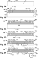
- Fig. 1 depicts an apparatus, shown here as a flexible connector 100, which could be a flexible circuit board connector, which can be used to electrically connect pairs of pads on mutually angularly arranged electronic components, as will be described in greater detail with circuit boards as an example in Fig. 2 .
- the flexible connector 100 can allow for stripline, coplanar waveguide, and/or microstrip routing, and has a high density of interconnects, which may be sufficient to provide hundreds to thousands of I/O connections on a 100-200 micrometer pitch.
- a unitary connector block 102 has first and second board- facing areas, shown generally at 104 and 106, respectively.
- the term "board-facing” is used here, for clarity of description, in the context of the circuit board example use environment, but it is contemplated that a "board” need not be present for another use environment of the flexible connector 100.
- the first and second board-facing areas 104 and 106 are longitudinally spaced from each other on a chosen surface (the lower side, in the orientation and configuration of Fig. 1 ) of the connector block 102.
- the "longitudinal" direction as referenced herein, is substantially horizontal in the orientation of Fig. 1 , and is represented by arrow "L".
- the connector block 102 includes a block body 108 transversely separating the chosen surface from an opposing surface (the upper side, in the orientation and configuration of Fig. 1 ) oppositely facing from the chosen surface.
- the "transverse" direction as referenced herein, is perpendicular to the longitudinal direction-thus, substantially vertical in the orientation of Fig. 1 --and is represented by arrow "T".
- the connector block 102 includes a flexible connector bridge 1 10 longitudinally interposed between the first and second board-facing areas 104 and 106.
- the connector bridge 1 10 and the first and second board-facing areas 104 and 106 may all be made from the same material.
- the connector block 102 could at least partially be made of a silicon wafer that has been processed, as will be described below or in any other suitable manner, to generate the connector bridge 1 10 as a reduced-thickness (including zero-thickness) portion, and the first and second board- facing areas 104 and 106 as a full-thickness portion, of the same original block of raw material.
- the connector bridge 1 10 and the first and second board- facing areas 104 and 106 may be concurrently and unitarily formed as a monolithic component of the connector block 102 (i.e., not intended for disassembly post- manufacture).
- the connector block 102 may have a first transverse thickness (t1 ) at the first and/or second board-facing areas 104 and 106, and a second transverse thickness (t2) at the connector bridge 1 10.
- the second transverse thickness t2 may be a minority (less than half as much), which may be a superminority (less than one third as much), of the first transverse thickness t1 .
- the first transverse thickness t1 could be in the range of 600-700 microns, such as in the range of 640-660 microns, while the second transverse thickness t2 could be in the range of 5-25 microns, such as in the range of 10-20 microns.
- silicon is sufficiently flexible across a thickness of 5-25 microns to permit bending through a range of angles as disclosed herein.
- the first and second transverse thicknesses t1 and t2 could be substantially similar, for a particular use environment.
- a selected one of the chosen surface and the opposing surface of the connector block 102 may be contoured at differing distances from the other one of the chosen surface and the opposing surface along a longitudinal dimension of the connector block 102, as shown.
- the opposing (top) surface of the connector block 1 02 when ready for use, may have a "stepped" profile (shown generally at P) which varies the distance of the opposing surface from the chosen (bottom) surface in a linear fashion.
- the profile of the selected one of the chosen surface and the opposing surface of the connector block 102 may vary in a curved, curvilinear, linear, or any desired fashion (e.g., at least partially sloped or curved), and that the profile could also or instead vary in any desired fashion (e.g., gradually or in a stepwise fashion) in a lateral (i.e., into and out of the plane of the page of Fig. 1 ) direction, to provide a flexible connector 100 having desired properties for a particular use environment. For example, there could be a "spike" or other protrusion in the longitudinal direction along profile P for any desired reason, including, but not limited to, use as a reinforcement or handling aid.
- the flexible connector 100 includes a first connector port 1 12 located within the first board-facing area 104.
- a second connector port 1 14 is located within the second board-facing area 106.
- a connector trace 1 16 (two labeled, in Fig. 1 ) extends through at least a portion of the block body 108 between the first and second board- facing areas 104 and 106. The connector trace 1 16 electrically connects the first and second connector ports 1 12 and 1 14.
- the chosen surface (in this Figure, the bottom surface, using the orientation of Fig. 1 ) of the flexible connector 100 faces first and second circuit boards 218 and 220, respectively for creating an electrical connection therebetween.
- the block body 108 is interposed between the chosen surface and the opposing surface.
- the flexible connector bridge 1 10, which is formed by a portion of the block body 108, is longitudinally interposed between the first and second board-facing areas 104 and 106 for facilitating relative angular motion of the first and second board- facing areas 104 and 106. In this manner, the flexible connector 100 can bend and flex to electrically connect pairs of pads 222 on mutually angularly arranged first and second circuit boards 218 and 220.
- the first and second circuit boards 218 and 220 are arranged relative to each other at an operative angle ⁇ .
- the operative angle ⁇ may be any desired angle which can be physically achieved by a predetermined configuration of the flexible connector 100.
- the operative angle ⁇ is approximately 90 °, or an orthogonal, "right" angle.
- One of ordinary skill in the art will be able to provide a flexible connector 100 having suitable dimensions (relative and absolute) and flexibility for spanning a desired operative angle ⁇ between first and second circuit boards 218 and 220.
- the block body 108 may include a plurality of laminated substrate layers.
- the block body 108 could include a portion (S) made of silicon, laminated with one or more layers of dialectric material (D), such as polymer, and/or metal (M).
- D dialectric material
- M metal
- each layer of metal could include a different level of conductive traces, as desired.
- Any flexible connector 100 can be configured as including, as shown in Fig. 1 , a planar chosen substrate (124, as shown in Fig. 1 ) having transversely spaced top and bottom chosen substrate surfaces 126 and 128, respectively, and first and second board-facing areas 104 and 106 being longitudinally spaced from each other on a selected one (here, bottom chosen substrate surface 128) of the top and bottom chosen substrate surfaces 126 and 128.
- a planar opposing substrate (130, as shown in Fig. 1 ) has transversely spaced top and bottom opposing substrate surfaces 132 and 134, respectively.
- a selected one (here, opposing substrate 130) of the chosen and opposing substrates 124 and 130 has a significantly varied transverse thickness along a longitudinal dimension thereof.
- a unitary connector block 102 is at least partially formed by the chosen and opposing substrates.
- the connector block 102 includes a block body 108.
- a first connector port 1 12 is located within the first board-facing area 104.
- a second connector port 1 14 is located within the second board-facing area 106.
- a connector trace 1 16 may extend through at least a portion of the block body 108 between the first and second board-facing areas 104 and 106. The connector trace 1 16 electrically connects the first and second connector ports 1 12 and 1 14.
- a flexible connector bridge 1 10 may be longitudinally interposed between the first and second board-facing areas 104 and 106 for facilitating relative angular motion of the first and second board-facing areas 104 and 106.
- This general description applies to any embodiment of the aspects of the disclosure shown and described herein. However, it should be noted that the substrate definitions and descriptions earlier in this paragraph apply to the configuration of the flexible connector 100 shown in Figs. 1 -2 , where the connector bridge 1 10 is positioned on the connector block 102 toward the "interior" side of operative angle ⁇ .
- the block body 1 08 includes at least one increased-thickness portion and at least one reduced-thickness portion, as with the previously described configuration of Figs. 1 -2 .
- the selected substrate layer 124 or 130 forming the chosen surface has a significantly varied transverse thickness along a longitudinal dimension thereof.
- each connector trace 1 16 of this configuration includes at least one via 436 extending transversely through an increased-thickness portion of the block body.
- the material of the chosen substrate 124 can have the previously described varying profile P while also including the first and second board-facing areas 104 and 106.
- One of ordinary skill in the art will understand how to design and manufacture the configuration of the flexible connector 100 shown in Figs. 3-4 . Therefore, the remainder of this description, and Figs. 5A-9C , will use the configuration of Figs. 1 -2 as an example, without excluding or prejudicing a corresponding characterization of the described and shown features and actions which uses the configuration of Figs. 3-4 .
- a base block characterized here as a silicon (or silicon on insulator) wafer or block "S" is provided.
- this block “S” is being described as a planar opposing substrate 130 having transversely spaced top and bottom opposing substrate surfaces 132 and 134.
- a planar chosen substrate 124 has transversely spaced top and bottom chosen substrate surfaces 126 and 128, which is depicted in Fig.
- First and second board-facing areas 104 and 106 longitudinally spaced from each other are defined on a selected one of the top and bottom chosen substrate surfaces-here, on the bottom chosen substrate surface 128. As shown also in Fig. 5B , the chosen and opposing substrates 124 and 130 are attached together to at least partially form a unitary connector block 102 including a block body 108 with the first and second board-facing areas 104 and 106 on an outward-facing surface thereof.
- a conductive material is deposited to generate at least one first connector port 1 12 located within the first board-facing area 104.
- a conductive material is deposited to generate at least one second connector port 1 14 located within the second board-facing area 106.
- the first and second connector ports 1 12 and 1 14 are shown and described herein as being "bump bonds”. It is also contemplated that the first and second connector ports 1 12 and 1 14 could instead or also include press contact type interfaces, but it may be desirable to include some sort of holdaway structures in the flexible connector 100 for press contact interfaces.
- a conductive material is deposited on at least one of the chosen and opposing substrate surfaces to generate a connector trace 1 16 extending through at least a portion of the block body 108 between the first and second board-facing areas 104 and 106. This could occur, for example, in any of Figs. 5B-5F .
- the first and second connector ports 1 12 and 1 14 are electrically connected with the connector trace 1 16.
- depositing a conductive material on at least one of the chosen and opposing substrate surfaces to generate a connector trace 1 16 may include creating at least one via 436 extending transversely through an increased- thickness portion of the block body 108.
- a "handle wafer” (not shown) could be removably attached to the chosen substrate surface to facilitate handling of the flexible connector 100 during manufacture without unduly stressing fragile portions of the structure.
- a thickness of the opposing substrate 130 is optionally reduced across an entire longitudinal dimension thereof, in any desired manner, particularly if the initial silicon S block provided is thicker than desired for the final flexible connector 100.
- a thickness of one of the chosen and opposing substrate surfaces, depending on the configuration is selectively reduced, to define a flexible connector bridge 1 10 longitudinally interposed between the first and second board-facing areas 104 and 106.
- selectively reducing a thickness of one of the chosen and opposing substrate surfaces to define the flexible connector bridge 1 10 may include selectively reducing a thickness of the selected one of the chosen and opposing substrate surfaces upon which the first and second board-facing areas 104 and 106 are defined.
- selectively reducing a thickness of one of the chosen and opposing substrate surfaces to define the flexible connector bridge 1 10 may include selectively reducing a thickness of the other one of the chosen and opposing substrate surfaces upon which the first and second board-facing areas 104 and 106 are defined.
- an elongated, mass- produced chain of flexible connector 100 units may be diced or singulated via etching, other chemical techniques, mechanical techniques, or in any other desired manner, into usable-length individual finished flexible connectors 100, by cutting a very long (into and out of the plane of the page in Figs. 5A-5F ) chain into strips.
- Each of the individual finished flexible connectors 100 may be, for example, in the range of 5-50 millimeters, and, more specifically, in the range of 10-30 millimeters, deep, again, into and out of the plane of the page, in these Figures.
- Each of the finished flexible connectors 100 may include facilitation of relative angular motion of the first and second board-facing areas 104 with the connector bridge 1 10.
- first and second mutually angularly arranged circuit boards 218 and 220 may be electrically connected with a flexible connector 100 including the connector block 102 at least partially formed via the sequence of Figs. 5A-5F .
- the first connector ports 1 12 on the first board-facing area 104 can be brought into electrical connection with appropriately located pads 222 on the first circuit board 218, and the second connector ports 1 14 on the second board-facing area 106 can be brought into electrical connection with corresponding pads 222 on the second circuit board 220.
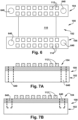
- FIG. 6-9C an orientation scheme for locating a flexible connector 100 as desired in relation to first and second circuit boards 218 and 220, is shown.
- At least one connector orientation feature 640 is provided to the connector block 102, optionally, as shown, in at least one of the first and second board-facing areas 104 and 106.
- the connector orientation features 640 can be full-depth (as shown in Fig. 7A ) or blind (as shown in Fig. 7B ) holes into/through the block body 108.
- the connector orientation features 640 are configured for selectively engaging corresponding board orientation features 842 on a corresponding first or second circuit board 218 or 220.
- the board orientation features 842 are depicted herein as pegs, in part to engage with the aperture type connector orientation features 640 in a male-to-female manner. However, it is contemplated that the board orientation features could be apertures for engaging with peg-type connector orientation features (neither shown) in a female-to-male manner. It is also contemplated that certain of the board orientation features could be apertures, and certain others could be pegs, with corresponding connector orientation features provided, as desired for a particular implementation of the flexible connector 100.
- pegs and apertures are shown for simplicity, it is contemplated that the pegs and apertures, or any other orientation feature structures, could have any suitable shape, configuration, number, placement, and/or mating or engaging features, as desired for a particular use environment.
- one or both of the orientation feature structures could be threaded or otherwise configured to facilitate engagement and maintenance of the flexible connector 100 with the circuit boards 218 and 220.
- the flexible connector 100 can be therefore guided into engagement, and the engagement optionally at least partially effectuated, through use of the connector and board orientation feature 640 and 842.
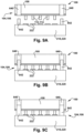
- This sequence of selectively engaging a board orientation feature 842 on a circuit board 218 or 220 with a corresponding connector orientation feature 640 on the flexible connector 100, in the course of electrically connecting first and second mutually angularly arranged circuit boards 218 and 220 with a flexible connector 1 10 including the connector block 120 is depicted in Figs. 9A-9C .
- Fig. 9A the flexible connector 100 is shown as being aligned as desired with respect to the circuit board 218 or 220 with the connector orientation features 640 poised for engagement with the board orientation features 842.
- Fig. 9B the flexible connector 100 has been lowered toward the circuit board 218 or 222 insert the board orientation features 842 into the connector orientation feature 640.
- the first or second connector ports 1 12 or 1 14 have been brought into electrical contact with the pads 222.
- one or both of the connector and board orientation features 640 and 842 has been heated to engage and optionally draw down the flexible connector 100 into desired contact with the pads 222 of the first and second circuit boards 218 and 220, particularly if a thermal coefficient of expansion mismatch technique is used.
- the flexible connector 100 could be removed from the first and second circuit boards 218 and 220 by simply reversing the above-described sequence of installation.
- the silicon wafer or other raw material could be completely removed (e.g., to a zero-thickness) at the connector bridge 1 10 to provide a connector bridge made from a different material than the first and second board-facing areas 104 and 106
- Any of the described structures and components could be disposable or reusable as desired for a particular use environment. Any component could be provided with a user-perceptible marking to indicate a material, configuration, at least one dimension, or the like pertaining to that component, the user-perceptible marking aiding a user in selecting one component from an array of similar components for a particular use environment.
- a "predetermined" status may be determined at any time before the structures being manipulated actually reach that status, the "predetermination" being made as late as immediately before the structure achieves the predetermined status.
- Certain structures and components are schematically depicted in the Figures as being slightly separated from one another, for clarity of depiction, but one of ordinary skill in the art will understand the contacting relationships between these structures, based at least upon context and the corresponding written description.
Landscapes
- Engineering & Computer Science (AREA)
- Microelectronics & Electronic Packaging (AREA)
- Manufacturing & Machinery (AREA)
- Combinations Of Printed Boards (AREA)
- Coupling Device And Connection With Printed Circuit (AREA)
- Structure Of Printed Boards (AREA)
Applications Claiming Priority (2)
| Application Number | Priority Date | Filing Date | Title |
|---|---|---|---|
| US15/377,670 US20180168042A1 (en) | 2016-12-13 | 2016-12-13 | Flexible connector |
| PCT/US2017/060867 WO2018111460A1 (en) | 2016-12-13 | 2017-11-09 | Flexible connector |
Publications (2)
| Publication Number | Publication Date |
|---|---|
| EP3556185A1 EP3556185A1 (en) | 2019-10-23 |
| EP3556185B1 true EP3556185B1 (en) | 2024-10-09 |
Family
ID=60409491
Family Applications (1)
| Application Number | Title | Priority Date | Filing Date |
|---|---|---|---|
| EP17801291.0A Active EP3556185B1 (en) | 2016-12-13 | 2017-11-09 | Flexible connector |
Country Status (7)
| Country | Link |
|---|---|
| US (2) | US20180168042A1 (enExample) |
| EP (1) | EP3556185B1 (enExample) |
| JP (1) | JP6834000B2 (enExample) |
| KR (1) | KR102286169B1 (enExample) |
| AU (1) | AU2017377926B2 (enExample) |
| CA (1) | CA3046344C (enExample) |
| WO (1) | WO2018111460A1 (enExample) |
Families Citing this family (15)
| Publication number | Priority date | Publication date | Assignee | Title |
|---|---|---|---|---|
| KR102337901B1 (ko) * | 2018-08-28 | 2021-12-08 | 주식회사 엘지에너지솔루션 | 인쇄회로기판 어셈블리 및 그것을 제조하는 제조방법 |
| IT201800009268A1 (it) * | 2018-10-09 | 2020-04-09 | Te Connectivity Italia Distrib Srl | Dispositivo di connessione |
| CN209376018U (zh) | 2018-11-14 | 2019-09-10 | 奥特斯(中国)有限公司 | 具有改进的弯曲性能的部件承载件 |
| CN110022644B (zh) * | 2019-05-16 | 2020-04-03 | 广州市宝米勒电气技术有限公司 | Pcb及其连接具有不同平面触点的元器件的方法、电子装置 |
| GB201910805D0 (en) | 2019-07-29 | 2019-09-11 | Leonardo Mw Ltd | Circuit board assembly |
| EP4005030A4 (en) * | 2019-07-31 | 2023-04-19 | Hewlett-Packard Development Company, L.P. | BOARD-TO-BOARD CONNECTORS |
| US11075486B1 (en) | 2020-03-02 | 2021-07-27 | Northrop Grumman Systems Corporation | Signal connector system |
| CN111369945B (zh) * | 2020-04-30 | 2021-05-04 | 京东方科技集团股份有限公司 | 电路板组件、显示装置、终端和信号处理系统 |
| US11038594B1 (en) | 2020-05-13 | 2021-06-15 | Northrop Grumman Systems Corporation | Self-insulating high bandwidth connector |
| US11569608B2 (en) | 2021-03-30 | 2023-01-31 | Northrop Grumman Systems Corporation | Electrical connector system |
| US11688962B2 (en) * | 2021-05-13 | 2023-06-27 | Veoneer Us, Llc | Scalable electronic modules having a common form factor |
| KR102930094B1 (ko) * | 2021-07-01 | 2026-02-25 | 삼성전자주식회사 | 경연성 인쇄 회로 기판 및 이를 포함하는 전자 장치 |
| CN114496358A (zh) * | 2022-01-21 | 2022-05-13 | 武汉衷华脑机融合科技发展有限公司 | 一种连接线结构及其形成方法 |
| JP7628191B2 (ja) * | 2022-10-12 | 2025-02-07 | ルイジェ ネットワークス カンパニー,リミテッド | チップツーモジュールのケーブルアセンブリ及びpcbボード回路 |
| US12494599B2 (en) | 2022-12-20 | 2025-12-09 | Northrop Grumman Systems Corporation | Silicon flexible connectors |
Family Cites Families (25)
| Publication number | Priority date | Publication date | Assignee | Title |
|---|---|---|---|---|
| DE2946726C2 (de) | 1979-11-20 | 1982-05-19 | Ruwel-Werke Spezialfabrik für Leiterplatten GmbH, 4170 Geldern | Leiterplatte mit starren und flexiblen Bereichen und Verfahren zu deren Herstellung |
| US4466184A (en) * | 1981-04-21 | 1984-08-21 | General Dynamics, Pomona Division | Method of making pressure point contact system |
| US4715928A (en) * | 1985-09-27 | 1987-12-29 | Hamby Bill L | Flexible printed circuits and methods of fabricating and forming plated thru-holes therein |
| US4687695A (en) * | 1985-09-27 | 1987-08-18 | Hamby Bill L | Flexible printed circuits and methods of fabricating and forming plated thru-holes therein |
| US5160269A (en) * | 1991-12-19 | 1992-11-03 | Precision Interconnect Corporation | Hydrostatic connector for flex circuits |
| US5161981A (en) * | 1992-03-10 | 1992-11-10 | Amp Incorporated | Foldable stacking connector |
| US5854534A (en) * | 1992-08-05 | 1998-12-29 | Fujitsu Limited | Controlled impedence interposer substrate |
| US5419038A (en) * | 1993-06-17 | 1995-05-30 | Fujitsu Limited | Method for fabricating thin-film interconnector |
| US6040624A (en) * | 1997-10-02 | 2000-03-21 | Motorola, Inc. | Semiconductor device package and method |
| US6603079B2 (en) * | 1999-02-05 | 2003-08-05 | Mack Technologies Florida, Inc. | Printed circuit board electrical interconnects |
| JP3744383B2 (ja) * | 2000-06-09 | 2006-02-08 | 松下電器産業株式会社 | 複合配線基板及びその製造方法 |
| US6721189B1 (en) * | 2002-03-13 | 2004-04-13 | Rambus, Inc. | Memory module |
| US6712620B1 (en) * | 2002-09-12 | 2004-03-30 | High Connection Density, Inc. | Coaxial elastomeric connector system |
| JP4196743B2 (ja) * | 2003-06-12 | 2008-12-17 | 沖電気工業株式会社 | 半導体記憶装置 |
| JP2005322878A (ja) * | 2004-04-09 | 2005-11-17 | Dainippon Printing Co Ltd | 印刷配線基板の組付パネル、印刷配線基板の実装用単位シート、リジッド−フレキシブル基板及びこれらの製造方法 |
| JP2006339088A (ja) * | 2005-06-06 | 2006-12-14 | Fci Asia Technology Pte Ltd | 電気コネクタ |
| US7438582B2 (en) * | 2006-12-22 | 2008-10-21 | Amphenol Corporation | Flexible circuit connector assembly |
| US8178789B2 (en) * | 2007-07-17 | 2012-05-15 | Ibiden Co., Ltd. | Wiring board and method of manufacturing wiring board |
| US8118611B2 (en) * | 2008-10-31 | 2012-02-21 | Myoungsoo Jeon | PCB bridge connector for connecting PCB devices |
| KR101051491B1 (ko) * | 2009-10-28 | 2011-07-22 | 삼성전기주식회사 | 다층 경연성 인쇄회로기판 및 다층 경연성 인쇄회로기판의 제조방법 |
| EP2728983A1 (de) * | 2012-10-30 | 2014-05-07 | Continental Automotive GmbH | Leiterplattenbaugruppe für ein Steuergerät, Steuergerät für ein Kraftfahrzeug und Signalverarbeitungsanordnung |
| US8878353B2 (en) | 2012-12-20 | 2014-11-04 | Invensas Corporation | Structure for microelectronic packaging with bond elements to encapsulation surface |
| TW201448688A (zh) * | 2013-06-03 | 2014-12-16 | Mutual Tek Ind Co Ltd | 複合式電路板及其製作方法 |
| JP6270344B2 (ja) | 2013-06-05 | 2018-01-31 | ソニーセミコンダクタソリューションズ株式会社 | 伝送モジュール、シールド方法及びコネクタ |
| CN205093052U (zh) * | 2013-07-30 | 2016-03-16 | 株式会社村田制作所 | 多层基板 |
-
2016
- 2016-12-13 US US15/377,670 patent/US20180168042A1/en not_active Abandoned
-
2017
- 2017-11-09 KR KR1020197015946A patent/KR102286169B1/ko active Active
- 2017-11-09 AU AU2017377926A patent/AU2017377926B2/en active Active
- 2017-11-09 JP JP2019528086A patent/JP6834000B2/ja active Active
- 2017-11-09 WO PCT/US2017/060867 patent/WO2018111460A1/en not_active Ceased
- 2017-11-09 EP EP17801291.0A patent/EP3556185B1/en active Active
- 2017-11-09 CA CA3046344A patent/CA3046344C/en active Active
-
2019
- 2019-06-12 US US16/439,415 patent/US10681812B2/en active Active
Also Published As
| Publication number | Publication date |
|---|---|
| CA3046344A1 (en) | 2018-06-21 |
| US20180168042A1 (en) | 2018-06-14 |
| CA3046344C (en) | 2021-04-27 |
| JP2019536294A (ja) | 2019-12-12 |
| US20190313530A1 (en) | 2019-10-10 |
| KR102286169B1 (ko) | 2021-08-06 |
| US10681812B2 (en) | 2020-06-09 |
| JP6834000B2 (ja) | 2021-02-24 |
| WO2018111460A1 (en) | 2018-06-21 |
| AU2017377926B2 (en) | 2020-06-18 |
| EP3556185A1 (en) | 2019-10-23 |
| KR20190077499A (ko) | 2019-07-03 |
| AU2017377926A1 (en) | 2019-05-23 |
Similar Documents
| Publication | Publication Date | Title |
|---|---|---|
| EP3556185B1 (en) | Flexible connector | |
| US9433104B2 (en) | Method of manufacturing stretchable circuit assemblies | |
| EP1855117A1 (en) | Contact for use in testing integrated circuits | |
| US8963013B2 (en) | Three dimensional interposer device | |
| US20050118842A1 (en) | Interconnection device | |
| US10877069B2 (en) | Inspection jig, substrate inspection device, and method for manufacturing inspection jig | |
| US9172165B1 (en) | Memory module connector assembly | |
| US10886670B2 (en) | PCB-based connector device | |
| US20140017940A1 (en) | Layered connector and method of manufacturing a layered connector | |
| US10109595B2 (en) | Double-sided package module and substrate strip | |
| US9252501B2 (en) | Millimeter scale three-dimensional antenna structures and methods for fabricating same | |
| CN102005657A (zh) | 挠性线束、电连接部件、电气电子部件模块及电连接方法 | |
| KR101745884B1 (ko) | 초정밀 레이저를 활용한 소켓 및 그 제조방법 | |
| CN107425345B (zh) | 连接器模块及其闸刀 | |
| KR100735351B1 (ko) | 커넥터가 장착된 배선 기판과 그 제조 방법 | |
| WO2010022183A1 (en) | Two-mount and three-mount socket design with coaxial attachment and alignment | |
| KR101694768B1 (ko) | 반도체 테스트 소켓 및 그 제조 방법 | |
| JP4746035B2 (ja) | 電気的接続装置 | |
| US20130323977A1 (en) | Electric connector | |
| CN110999549A (zh) | 电气装置 | |
| KR101848631B1 (ko) | 테스트 소켓의 제조 방법 | |
| KR20150051971A (ko) | 반도체 장치의 제조방법 및 반도체 제조장치 | |
| JP2003297520A (ja) | コンタクトシートの製造方法 | |
| HK1111226A (en) | Contact for use in testing integrated circuits | |
| JPH06188541A (ja) | プリント基板のカードエッジ端子 |
Legal Events
| Date | Code | Title | Description |
|---|---|---|---|
| STAA | Information on the status of an ep patent application or granted ep patent |
Free format text: STATUS: UNKNOWN |
|
| STAA | Information on the status of an ep patent application or granted ep patent |
Free format text: STATUS: THE INTERNATIONAL PUBLICATION HAS BEEN MADE |
|
| PUAI | Public reference made under article 153(3) epc to a published international application that has entered the european phase |
Free format text: ORIGINAL CODE: 0009012 |
|
| STAA | Information on the status of an ep patent application or granted ep patent |
Free format text: STATUS: REQUEST FOR EXAMINATION WAS MADE |
|
| 17P | Request for examination filed |
Effective date: 20190715 |
|
| AK | Designated contracting states |
Kind code of ref document: A1 Designated state(s): AL AT BE BG CH CY CZ DE DK EE ES FI FR GB GR HR HU IE IS IT LI LT LU LV MC MK MT NL NO PL PT RO RS SE SI SK SM TR |
|
| AX | Request for extension of the european patent |
Extension state: BA ME |
|
| DAV | Request for validation of the european patent (deleted) | ||
| DAX | Request for extension of the european patent (deleted) | ||
| STAA | Information on the status of an ep patent application or granted ep patent |
Free format text: STATUS: EXAMINATION IS IN PROGRESS |
|
| 17Q | First examination report despatched |
Effective date: 20211014 |
|
| P01 | Opt-out of the competence of the unified patent court (upc) registered |
Effective date: 20230607 |
|
| GRAP | Despatch of communication of intention to grant a patent |
Free format text: ORIGINAL CODE: EPIDOSNIGR1 |
|
| STAA | Information on the status of an ep patent application or granted ep patent |
Free format text: STATUS: GRANT OF PATENT IS INTENDED |
|
| INTG | Intention to grant announced |
Effective date: 20240612 |
|
| GRAS | Grant fee paid |
Free format text: ORIGINAL CODE: EPIDOSNIGR3 |
|
| GRAA | (expected) grant |
Free format text: ORIGINAL CODE: 0009210 |
|
| STAA | Information on the status of an ep patent application or granted ep patent |
Free format text: STATUS: THE PATENT HAS BEEN GRANTED |
|
| AK | Designated contracting states |
Kind code of ref document: B1 Designated state(s): AL AT BE BG CH CY CZ DE DK EE ES FI FR GB GR HR HU IE IS IT LI LT LU LV MC MK MT NL NO PL PT RO RS SE SI SK SM TR |
|
| REG | Reference to a national code |
Ref country code: CH Ref legal event code: EP |
|
| REG | Reference to a national code |
Ref country code: DE Ref legal event code: R096 Ref document number: 602017085383 Country of ref document: DE |
|
| REG | Reference to a national code |
Ref country code: IE Ref legal event code: FG4D |
|
| REG | Reference to a national code |
Ref country code: LT Ref legal event code: MG9D |
|
| REG | Reference to a national code |
Ref country code: NL Ref legal event code: MP Effective date: 20241009 |
|
| REG | Reference to a national code |
Ref country code: AT Ref legal event code: MK05 Ref document number: 1732070 Country of ref document: AT Kind code of ref document: T Effective date: 20241009 |
|
| PG25 | Lapsed in a contracting state [announced via postgrant information from national office to epo] |
Ref country code: NL Free format text: LAPSE BECAUSE OF FAILURE TO SUBMIT A TRANSLATION OF THE DESCRIPTION OR TO PAY THE FEE WITHIN THE PRESCRIBED TIME-LIMIT Effective date: 20241009 |
|
| PG25 | Lapsed in a contracting state [announced via postgrant information from national office to epo] |
Ref country code: NL Free format text: LAPSE BECAUSE OF FAILURE TO SUBMIT A TRANSLATION OF THE DESCRIPTION OR TO PAY THE FEE WITHIN THE PRESCRIBED TIME-LIMIT Effective date: 20241009 |
|
| PG25 | Lapsed in a contracting state [announced via postgrant information from national office to epo] |
Ref country code: PT Free format text: LAPSE BECAUSE OF FAILURE TO SUBMIT A TRANSLATION OF THE DESCRIPTION OR TO PAY THE FEE WITHIN THE PRESCRIBED TIME-LIMIT Effective date: 20250210 Ref country code: IS Free format text: LAPSE BECAUSE OF FAILURE TO SUBMIT A TRANSLATION OF THE DESCRIPTION OR TO PAY THE FEE WITHIN THE PRESCRIBED TIME-LIMIT Effective date: 20250209 Ref country code: HR Free format text: LAPSE BECAUSE OF FAILURE TO SUBMIT A TRANSLATION OF THE DESCRIPTION OR TO PAY THE FEE WITHIN THE PRESCRIBED TIME-LIMIT Effective date: 20241009 |
|
| PG25 | Lapsed in a contracting state [announced via postgrant information from national office to epo] |
Ref country code: FI Free format text: LAPSE BECAUSE OF FAILURE TO SUBMIT A TRANSLATION OF THE DESCRIPTION OR TO PAY THE FEE WITHIN THE PRESCRIBED TIME-LIMIT Effective date: 20241009 |
|
| PG25 | Lapsed in a contracting state [announced via postgrant information from national office to epo] |
Ref country code: BG Free format text: LAPSE BECAUSE OF FAILURE TO SUBMIT A TRANSLATION OF THE DESCRIPTION OR TO PAY THE FEE WITHIN THE PRESCRIBED TIME-LIMIT Effective date: 20241009 |
|
| PG25 | Lapsed in a contracting state [announced via postgrant information from national office to epo] |
Ref country code: ES Free format text: LAPSE BECAUSE OF FAILURE TO SUBMIT A TRANSLATION OF THE DESCRIPTION OR TO PAY THE FEE WITHIN THE PRESCRIBED TIME-LIMIT Effective date: 20241009 |
|
| PG25 | Lapsed in a contracting state [announced via postgrant information from national office to epo] |
Ref country code: NO Free format text: LAPSE BECAUSE OF FAILURE TO SUBMIT A TRANSLATION OF THE DESCRIPTION OR TO PAY THE FEE WITHIN THE PRESCRIBED TIME-LIMIT Effective date: 20250109 |
|
| PG25 | Lapsed in a contracting state [announced via postgrant information from national office to epo] |
Ref country code: LV Free format text: LAPSE BECAUSE OF FAILURE TO SUBMIT A TRANSLATION OF THE DESCRIPTION OR TO PAY THE FEE WITHIN THE PRESCRIBED TIME-LIMIT Effective date: 20241009 Ref country code: GR Free format text: LAPSE BECAUSE OF FAILURE TO SUBMIT A TRANSLATION OF THE DESCRIPTION OR TO PAY THE FEE WITHIN THE PRESCRIBED TIME-LIMIT Effective date: 20250110 Ref country code: AT Free format text: LAPSE BECAUSE OF FAILURE TO SUBMIT A TRANSLATION OF THE DESCRIPTION OR TO PAY THE FEE WITHIN THE PRESCRIBED TIME-LIMIT Effective date: 20241009 |
|
| PG25 | Lapsed in a contracting state [announced via postgrant information from national office to epo] |
Ref country code: PL Free format text: LAPSE BECAUSE OF FAILURE TO SUBMIT A TRANSLATION OF THE DESCRIPTION OR TO PAY THE FEE WITHIN THE PRESCRIBED TIME-LIMIT Effective date: 20241009 |
|
| PG25 | Lapsed in a contracting state [announced via postgrant information from national office to epo] |
Ref country code: RS Free format text: LAPSE BECAUSE OF FAILURE TO SUBMIT A TRANSLATION OF THE DESCRIPTION OR TO PAY THE FEE WITHIN THE PRESCRIBED TIME-LIMIT Effective date: 20250109 |
|
| PG25 | Lapsed in a contracting state [announced via postgrant information from national office to epo] |
Ref country code: SM Free format text: LAPSE BECAUSE OF FAILURE TO SUBMIT A TRANSLATION OF THE DESCRIPTION OR TO PAY THE FEE WITHIN THE PRESCRIBED TIME-LIMIT Effective date: 20241009 |
|
| PG25 | Lapsed in a contracting state [announced via postgrant information from national office to epo] |
Ref country code: MC Free format text: LAPSE BECAUSE OF FAILURE TO SUBMIT A TRANSLATION OF THE DESCRIPTION OR TO PAY THE FEE WITHIN THE PRESCRIBED TIME-LIMIT Effective date: 20241009 |
|
| PG25 | Lapsed in a contracting state [announced via postgrant information from national office to epo] |
Ref country code: DK Free format text: LAPSE BECAUSE OF FAILURE TO SUBMIT A TRANSLATION OF THE DESCRIPTION OR TO PAY THE FEE WITHIN THE PRESCRIBED TIME-LIMIT Effective date: 20241009 |
|
| REG | Reference to a national code |
Ref country code: DE Ref legal event code: R097 Ref document number: 602017085383 Country of ref document: DE |
|
| PG25 | Lapsed in a contracting state [announced via postgrant information from national office to epo] |
Ref country code: LU Free format text: LAPSE BECAUSE OF NON-PAYMENT OF DUE FEES Effective date: 20241109 |
|
| PG25 | Lapsed in a contracting state [announced via postgrant information from national office to epo] |
Ref country code: EE Free format text: LAPSE BECAUSE OF FAILURE TO SUBMIT A TRANSLATION OF THE DESCRIPTION OR TO PAY THE FEE WITHIN THE PRESCRIBED TIME-LIMIT Effective date: 20241009 |
|
| PG25 | Lapsed in a contracting state [announced via postgrant information from national office to epo] |
Ref country code: RO Free format text: LAPSE BECAUSE OF FAILURE TO SUBMIT A TRANSLATION OF THE DESCRIPTION OR TO PAY THE FEE WITHIN THE PRESCRIBED TIME-LIMIT Effective date: 20241009 |
|
| PG25 | Lapsed in a contracting state [announced via postgrant information from national office to epo] |
Ref country code: SK Free format text: LAPSE BECAUSE OF FAILURE TO SUBMIT A TRANSLATION OF THE DESCRIPTION OR TO PAY THE FEE WITHIN THE PRESCRIBED TIME-LIMIT Effective date: 20241009 |
|
| PG25 | Lapsed in a contracting state [announced via postgrant information from national office to epo] |
Ref country code: CZ Free format text: LAPSE BECAUSE OF FAILURE TO SUBMIT A TRANSLATION OF THE DESCRIPTION OR TO PAY THE FEE WITHIN THE PRESCRIBED TIME-LIMIT Effective date: 20241009 |
|
| PG25 | Lapsed in a contracting state [announced via postgrant information from national office to epo] |
Ref country code: IT Free format text: LAPSE BECAUSE OF FAILURE TO SUBMIT A TRANSLATION OF THE DESCRIPTION OR TO PAY THE FEE WITHIN THE PRESCRIBED TIME-LIMIT Effective date: 20241009 |
|
| PLBE | No opposition filed within time limit |
Free format text: ORIGINAL CODE: 0009261 |
|
| STAA | Information on the status of an ep patent application or granted ep patent |
Free format text: STATUS: NO OPPOSITION FILED WITHIN TIME LIMIT |
|
| REG | Reference to a national code |
Ref country code: BE Ref legal event code: MM Effective date: 20241130 |
|
| PG25 | Lapsed in a contracting state [announced via postgrant information from national office to epo] |
Ref country code: SE Free format text: LAPSE BECAUSE OF FAILURE TO SUBMIT A TRANSLATION OF THE DESCRIPTION OR TO PAY THE FEE WITHIN THE PRESCRIBED TIME-LIMIT Effective date: 20241009 |
|
| 26N | No opposition filed |
Effective date: 20250710 |
|
| PG25 | Lapsed in a contracting state [announced via postgrant information from national office to epo] |
Ref country code: BE Free format text: LAPSE BECAUSE OF NON-PAYMENT OF DUE FEES Effective date: 20241130 |
|
| PG25 | Lapsed in a contracting state [announced via postgrant information from national office to epo] |
Ref country code: IE Free format text: LAPSE BECAUSE OF NON-PAYMENT OF DUE FEES Effective date: 20241109 |
|
| REG | Reference to a national code |
Ref country code: CH Ref legal event code: U11 Free format text: ST27 STATUS EVENT CODE: U-0-0-U10-U11 (AS PROVIDED BY THE NATIONAL OFFICE) Effective date: 20251201 |
|
| PGFP | Annual fee paid to national office [announced via postgrant information from national office to epo] |
Ref country code: DE Payment date: 20251119 Year of fee payment: 9 |
|
| PGFP | Annual fee paid to national office [announced via postgrant information from national office to epo] |
Ref country code: GB Payment date: 20251121 Year of fee payment: 9 |
|
| PGFP | Annual fee paid to national office [announced via postgrant information from national office to epo] |
Ref country code: FR Payment date: 20251126 Year of fee payment: 9 |
|
| PGFP | Annual fee paid to national office [announced via postgrant information from national office to epo] |
Ref country code: CH Payment date: 20251201 Year of fee payment: 9 |
|
| PG25 | Lapsed in a contracting state [announced via postgrant information from national office to epo] |
Ref country code: HU Free format text: LAPSE BECAUSE OF FAILURE TO SUBMIT A TRANSLATION OF THE DESCRIPTION OR TO PAY THE FEE WITHIN THE PRESCRIBED TIME-LIMIT; INVALID AB INITIO Effective date: 20171109 |
|
| PG25 | Lapsed in a contracting state [announced via postgrant information from national office to epo] |
Ref country code: CY Free format text: LAPSE BECAUSE OF FAILURE TO SUBMIT A TRANSLATION OF THE DESCRIPTION OR TO PAY THE FEE WITHIN THE PRESCRIBED TIME-LIMIT; INVALID AB INITIO Effective date: 20171109 |